Embed Size (px)
Citation preview

Int. J. Manufacturing Research, Vol.
Copyright © 2010 Inderscience Enterprises Ltd.
A novel approach to fixture design based on locating correctness
G.H. Qin School of Aeronautical Manufacturing Engineering, Nanchang Hangkong University, P.O. Box 3, 330063 Nanchang, Jiangxi, China
W.H. Zhang* and M. Wan Sino-French Laboratory of Concurrent Engineering, The Key Laboratory of Contemporary Design and Integrated Manufacturing Technology, Ministry of Education, Northwestern Polytechnical University, P.O. Box 552, 710072 Xi’an, Shaanxi, China E-mail: [email protected] *Corresponding author
S.P. Sun School of Aeronautical Manufacturing Engineering, Nanchang Hangkong University, P.O. Box 3, 330063 Nanchang, Jiangxi, China
Abstract: In a machining process, since the geometric accuracy of a manufacturing workpiece mainly relies on the relative position of workpiece to the machining tool, fixtures are needed to locate the workpiece. The clear concept of locating correctness is presented based on Venn diagram and a general algorithm is proposed to determine the locator number and layout. On one hand, the theoretical and practical constrained DOFs are formulated as a function of the machining requirement and the locating scheme, respectively. On the other hand, some criteria are concluded to analyse the locating correctness and modify the locating scheme with locating incorrectness.
[Received 6 May 2008; Revised 27 July 2009; Accepted 20 August 2009]
Keywords: CAFD; computer-aided fixture design; locating correctness; degree of freedom; machining requirement.
Reference to this paper should be made as follows: Qin, G.H., Zhang, W.H., Wan, M. and Sun, S.P. (2010) ‘A novel approach to fixture design based on locating correctness’, Int. J. Manufacturing Research, Vol.
Biographical notes: G.H. Qin is a Professor of School of Aeronautical Manufacturing Engineering at Nanchang Hangkong University carrying research in the area of NC machining technology. He holds a PhD in Aeronautical and Astronautical Manufacturing Engineering from Northwestern

430 G.H. Qin et al.
Polytechnical University. His research interests include analysis and optimisation of workpiece fixturing, mathematical model and simulation technology of machining process, and computer-aided fixture design technology.
W.H. Zhang was nominated as the Cheung Kong Chair Professor at Northwestern Polytechnical University in 1999. He serves now as Dean of School of Science. He got his PhD from the University of Liege, Belgium, in 1991. His research interests include lightweight structural optimisation, design optimisation of machining parameters and process, finite element prediction of machining deformation of the workpiece and numerical prediction of machining process.
M. Wan is an Associate Professor of Manufacturing Engineering at Northwestern Polytechnical University. He served as the anonymous referee of International Journal of Advanced Manufacturing Technology, Journal of Materials Processing Technology and Journal of Applied Mathematical Modeling. His research interests include high productivity and precision machining, analysis and modelling of machine tools, and machine tool dynamics, mechanical vibrations and modal analysis.
S.P. Sun is a Faculty Member at Nanchang Hangkong University carrying research in the area of design and manufacturing of composite material. He holds a PhD in Aeronautical and Astronautical Manufacturing Engineering from Northwestern Polytechnical University. His research interests include topology optimisation of materials and structures, and computer-aided design technology.
1 Introduction
During the machining operation, the function of a fixture is to ensure the location of the workpiece being manufactured to satisfy the manufacturing quality and locators are frequently used in contact with the workpiece to restrain related degrees of freedom. Therefore, the fixture-locating scheme, i.e., the locator number and layout, is needed to be correctly determined.
Traditional fixture designs were mainly based on some empirical principles (Hoffman, 1991). A drawing of fixture design is often prepared based on the processing plan and the workpiece information. Since the 1980s, the developments of Computer-Aided Fixture Design (CAFD) techniques have shortened greatly the time needed for fixture design and burdensome tasks such as consulting handbooks of jig and fixture design, drawing all assembly views and compiling a technical documentation have become greatly simplified. However, the fixture specification for the machining strongly depends on the designer’s experience and knowledge (Rong and Zhu, 1999).
For this reason, considerable efforts have been made to develop CAFD techniques. Representative works are as follows. Asada and By (1985) and Hong et al. (1996) developed a kinematic model of the locating scheme using Taylor expansion. The full-rank Jacobian matrix of the kinematic model is considered as a criterion to verify the complete location. Chou et al. (1989) and Trappey and Liu (1992) used the screw theory to formulate the fixturing equilibrium equation for a rigid prismatic workpiece. It concluded that the locating wrenches matrix of the fixturing equilibrium
A novel approach to fixture design based on locating correctness 431
equation needs to be full rank for the complete location. In fact, as the complete location is only one of the locating schemes being able to hold the workpiece in the desired position, the above-mentioned work was extended later by Kang et al. (2003) and Song and Rong (2005) to study non-deterministic location such as under- and over-locations. When the locating scheme is assumed to be correct, Wang (2002), Cai et al. (1997) and Qin et al. (2006) can optimise the locator dimensions and positions.
The above-mentioned investigations laid a good foundation for designing fixture-locating schemes. The locating correctness and the modification of incorrect locating scheme are, however, not addressed. This paper presents a new systematical approach to deal with the fixture design on the basis of the locating correctness.
2 Locating correctness
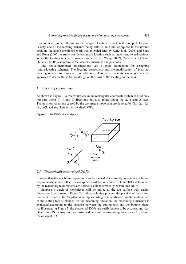
As shown in Figure 1, a free workpiece in the rectangular coordinate system can not only translate along X, Y and Z directions but also rotate about the X, Y and Z axes. The position variations caused by the workpiece movement are denoted by δxw, δyw, δzw, δαw, δβw and δγw. This is the so-called DOFs.
Figure 1 Six DOFs of a workpiece
2.1 Theoretically constrained DOFs
In order that the machining operation can be carried out correctly to obtain machining requirements, some DOFs of a workpiece must be constrained. These DOFs determined by the machining requirements are defined as the theoretically constrained DOFs.
Suppose a batch of workpieces will be milled at the top surface with design dimension h, as shown in Figure 2. In the machining process, the position of the cutting tool with respect to the XZ plane is set up according to h in advance. As the motion path of the cutting tool is planned for the machining operation, the machining dimension is evaluated according to the distance between the cutting tool and the bottom plane. As illustrated in Figure 3, the theoretical DOFs are easily known to be δyw, δαw and δγw. Other three DOFs may not be constrained because the machining dimensions h1, h3 and h5 are equal to h.

432 G.H. Qin et al.
Figure 2 The machining feature and its machining requirements
Figure 3 Theoretically constrained DOFs: (a) effect of δxw on h; (b) effect of δyw on h; (c) effect of δyw on h; (d) effect of δαw on h; (e) effect of δβw on h and (f) effect of δγw on h (see online version for colours)
(a) (b)
(c) (d)
(e) (f)
2.2 Practically constrained DOFs
During a machining operation, the theoretically constrained DOFs are constrained by fixture-locating scheme. Therefore, it is crucial for design dimensions to configure a feasible locating scheme. In principle, design of a locating scheme is to lay out a certain number of locators on the workpiece. A variety of locating schemes will be obtained by changing the number and layout of locators as shown in Figures 4–6.
A novel approach to fixture design based on locating correctness 433
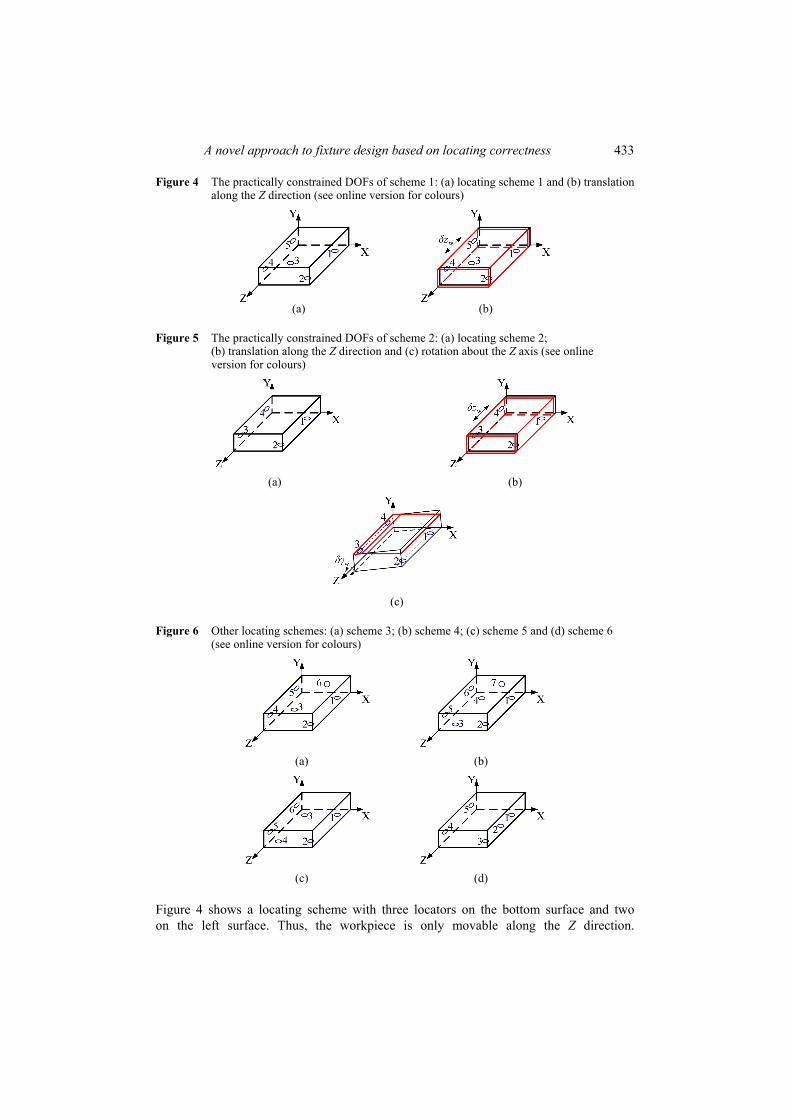
Figure 4 The practically constrained DOFs of scheme 1: (a) locating scheme 1 and (b) translation along the Z direction (see online version for colours)
(a) (b)
Figure 5 The practically constrained DOFs of scheme 2: (a) locating scheme 2; (b) translation along the Z direction and (c) rotation about the Z axis (see online version for colours)
(a) (b)
(c)
Figure 6 Other locating schemes: (a) scheme 3; (b) scheme 4; (c) scheme 5 and (d) scheme 6 (see online version for colours)
(a) (b)
(c) (d)
Figure 4 shows a locating scheme with three locators on the bottom surface and two on the left surface. Thus, the workpiece is only movable along the Z direction.
434 G.H. Qin et al.
The locating scheme shown in Figure 5 has two locators on the bottom and left surface, respectively. In this case, the workpiece is obviously free to either translate along the Z direction or rotate about the Z axis when locators 1 and 2 are arranged in parallel with the Z axis. This means that different locating schemes can constrain different DOFs. From the above-mentioned analyses, we know that locating scheme 1 constrains δxw, δyw, δαw, δβw and δγw whereas locating scheme 2 eliminates δxw, δyw, δαw and δβw. Here, the DOFs constrained by the locating scheme are called practically constrained DOFs.
By analogy, we can also investigate the practically constrained DOFs determined by other locating schemes shown in Figure 6. In cases of Figure 6(a) and (b), the practically constrained DOFs are δxw, δyw, δzw, δαw, δβw and δγw. The practically constrained DOFs of Schemes 5 and 6 are the same as in Schemes 1 and 2.
2.3 Logical relationship
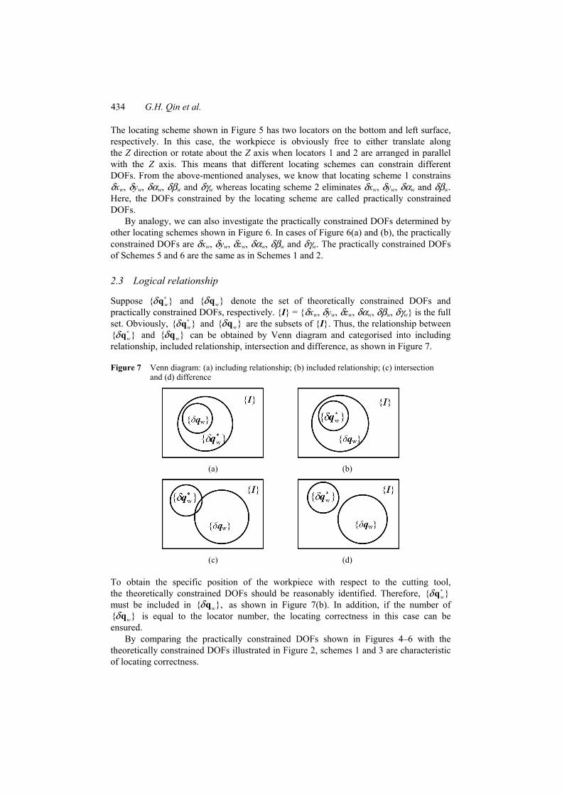
Suppose { }wδ ∗q and { }wδq denote the set of theoretically constrained DOFs and practically constrained DOFs, respectively. {I} = {δxw, δyw, δzw, δαw, δβw, δγw} is the full set. Obviously, { }wδ ∗q and { }wδq are the subsets of {I}. Thus, the relationship between { }wδ ∗q and { }wδq can be obtained by Venn diagram and categorised into including relationship, included relationship, intersection and difference, as shown in Figure 7.
Figure 7 Venn diagram: (a) including relationship; (b) included relationship; (c) intersection and (d) difference
(a) (b)
(c) (d)
To obtain the specific position of the workpiece with respect to the cutting tool, the theoretically constrained DOFs should be reasonably identified. Therefore, { }wδ ∗q must be included in { },wδq as shown in Figure 7(b). In addition, if the number of { }wδq is equal to the locator number, the locating correctness in this case can be ensured.
By comparing the practically constrained DOFs shown in Figures 4–6 with the theoretically constrained DOFs illustrated in Figure 2, schemes 1 and 3 are characteristic of locating correctness.
A novel approach to fixture design based on locating correctness 435
3 Algorithm of fixture design
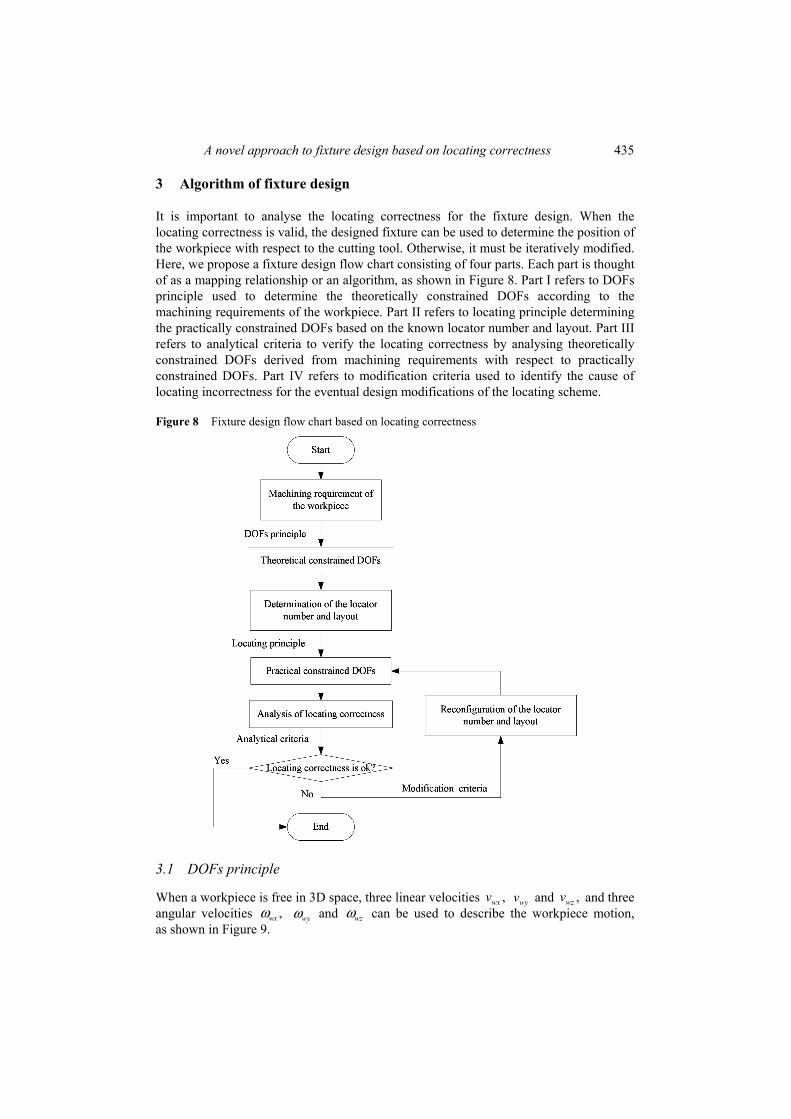
It is important to analyse the locating correctness for the fixture design. When the locating correctness is valid, the designed fixture can be used to determine the position of the workpiece with respect to the cutting tool. Otherwise, it must be iteratively modified. Here, we propose a fixture design flow chart consisting of four parts. Each part is thought of as a mapping relationship or an algorithm, as shown in Figure 8. Part I refers to DOFs principle used to determine the theoretically constrained DOFs according to the machining requirements of the workpiece. Part II refers to locating principle determining the practically constrained DOFs based on the known locator number and layout. Part III refers to analytical criteria to verify the locating correctness by analysing theoretically constrained DOFs derived from machining requirements with respect to practically constrained DOFs. Part IV refers to modification criteria used to identify the cause of locating incorrectness for the eventual design modifications of the locating scheme.
Figure 8 Fixture design flow chart based on locating correctness
3.1 DOFs principle
When a workpiece is free in 3D space, three linear velocities ,wxv wyv and ,wzv and three angular velocities ,wxω wyω and wzω can be used to describe the workpiece motion, as shown in Figure 9.

436 G.H. Qin et al.
Figure 9 Description of the workpiece motion (see online version for colours)
It is well known that both the position and the dimension accuracies of a machining surface depend on the fixture design. In fact, [ , , ]T
w wx wy wzω ω ω=ω causes the orientation errors whereas both [ , , ]T
w wx wy wzv v v=v and wω produce the location errors or dimension errors. Here, the position error is divided into the orientation error (such as the parallelism error and the perpendicularity error) and the location error (such as the coaxiality error and the symmetry error).
Let [ , , ]TP P P Px y z=r denote the coordinates of an arbitrary point P in the global
coordinate system {XYZ}. Thus, the orientation error can be described as
.PO w P= ×v ω r (1)
To study the relationship between the workpiece DOFs and its machining requirement, equation (1) is rewritten in differentiation form
PO wy P wz P w P w P
PO wz P wx P w P w P
PO wx P wy P w P w P
x z y z yy x z x zz y z y x
δ ω ω δβ δγδ ω ω δγ δαδ ω ω δα δβ
− − = − = − − −
(2)
where * [ , ] [ , , , , , ]T T T Tw w w w w w w w wx y zδ δ δ δ δα δβ δγ= =q v ω represents the desired DOF
vector of the workpiece to be constrained correspondingly. In addition, according to the velocity composition law of a kinematic particle, the
absolute velocity vP is the vector sum of the relative velocity vO and the transportation velocity vPO of point P. The following equation can be obtained as
P O PO= +v v v (3)
with
.O w=v v (4)
The substitution of equations (1) and (4) into equation (3) produces the location errors or dimension errors written as
A novel approach to fixture design based on locating correctness 437
.P w w P w P
P w w P w P
P w w P w P
x x z yy y x zz z y x
δ δ δβ δγδ δ δγ δαδ δ δα δβ
+ − = + − + −
(5)
It is worth noticing that the above-mentioned relation is valid only when point P is selected as a point on the reference related to the machining requirements. According to equations (2) and (5), only when some or all six DOFs of the workpiece are constrained, the machining accuracy can be ensured.
For example, if the machining dimension is aligned in X direction, the following equation can be obtained from equation (5),
0.P w w P w Px x z yδ δ δβ δγ= + − = (6)
Because Py and Pz can take arbitrary values, equation (6) is valid if and only if
0.w w wxδ δβ δγ= = = (7)
In other words, only when three DOFs ( , , )w w wxδ δβ δγ are constrained, the machining operation is correct. Thus
* [0, , , , 0,0]Tw y z αδ λ λ λ=q (8)
where ,yλ zλ and αλ are arbitrary numbers.
3.2 Locating principle
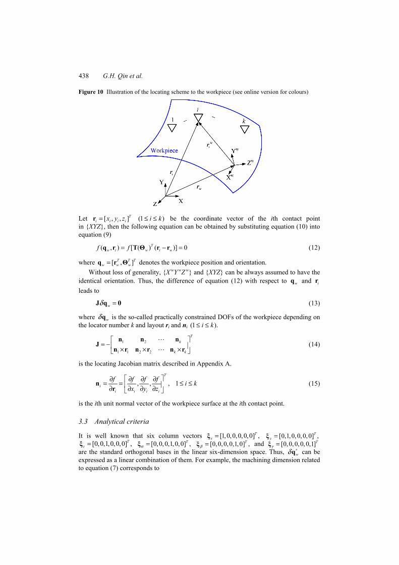
As shown in Figure 10, the locating scheme consists of k (i = 1, 2, …, k) locators. Suppose that the workpiece is a rigid body with a contact surface described by a piecewise differentiable function in the workpiece coordinate system {X
wY wZ
w}. If [ , , ]w w w w T
i i i ix y z=r designates the coordinate vector of ith contact point on the workpiece with respect to {X
wY wZ
w}, the contact surface of the workpiece is represented as
( ) 0.wif =r (9)
If the orientation and position of the workpiece are known, the ith contact point wir
can be mapped from {X wY
wZ w} to {XYZ} following
( ) wi w i w= +r T Θ r r (10)
where [ , , ]Tw w w wx y z=r denotes the position of the origin of {X
wY wZ
w} in {XYZ}. [ , , ]T
w w w wα β γ=Θ is the orientation of {X wY
wZ w} with respect to {XYZ}. And
( )w w w w w w w w w w w w
w w w w w w w w w w w w w
w w w w w
cβ cγ cα sγ sα sβ cγ sα sγ cα sβ cγcβ sγ cα cγ sα sβ sγ sα cγ cα sβ sγ
sβ sα cβ cα cβ
− + + = + − + −
T Θ (11)
is an orthogonal rotation matrix with c = cos and s = sin.
438 G.H. Qin et al.
Figure 10 Illustration of the locating scheme to the workpiece (see online version for colours)
Let [ , , ]Ti i i ix y z=r (1 )i k≤ ≤ be the coordinate vector of the ith contact point
in {XYZ}, then the following equation can be obtained by substituting equation (10) into equation (9)
( , ) [ ( ) ( )] 0Tw i w i wf f= − =q r T Θ r r (12)
where [ , ]T T Tw w w=q r Θ denotes the workpiece position and orientation.
Without loss of generality, {X wY
wZ w} and {XYZ} can be always assumed to have the
identical orientation. Thus, the difference of equation (12) with respect to wq and ir leads to
wδ =J q 0 (13)
where wδq is the so-called practically constrained DOFs of the workpiece depending on the locator number k and layout ri and ni (1 ).i k≤ ≤
1 2
1 1 2 2
Tk
k k
= − × × ×
n n nJ
n r n r n r (14)
is the locating Jacobian matrix described in Appendix A.
, , , 1T
ii i i i
f f f f i kx y z
∂ ∂ ∂ ∂= = ≤ ≤ ∂ ∂ ∂ ∂ n
r (15)
is the ith unit normal vector of the workpiece surface at the ith contact point.
3.3 Analytical criteria
It is well known that six column vectors [1,0,0,0,0,0] ,Tx =ξ [0,1,0,0,0,0] ,T
y =ξ [0,0,1,0,0,0] ,T
z =ξ [0,0,0,1,0,0] ,Tα =ξ [0,0,0,0,1,0] ,T
β =ξ and [0,0,0,0,0,1]Tγ =ξ
are the standard orthogonal bases in the linear six-dimension space. Thus, wδ ∗q can be expressed as a linear combination of them. For example, the machining dimension related to equation (7) corresponds to
A novel approach to fixture design based on locating correctness 439
0 0 0w x y y z z α α β γδ λ λ λ∗ = + + + + + =q ξ ξ ξ ξ ξ ξ ξλ (16)
where [ , , ]y z α=ξ ξ ξ ξ is the base vector involved in .wδ ∗q [ , , ]Ty z αλ λ λ=λ is the constant
vector with arbitrary numbers ,yλ zλ and .αλ Let rank( )ξ denote the rank of the base vector involved in ,wδ ∗q the number of
theoretically unconstrained DOFs in wδ ∗q can be known to be rank( ).ξ If m vector bases in wδ ∗q are not the solutions of equation (13), rank( ) m−ξ is then the number of DOFs belonging to the practically constrained DOFs. Some analytical criteria can be derived here to verify the locating correctness.
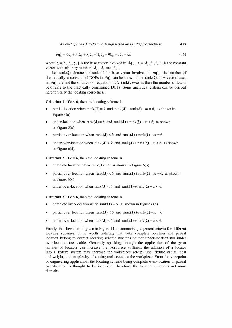
Criterion 1: If k < 6, then the locating scheme is
• partial location when rank( ) k=J and rank( ) rank( ) 6,m+ − =J ξ as shown in Figure 4(a)
• under-location when rank( ) k=J and rank( ) rank( ) 6,m+ − <J ξ as shown in Figure 5(a)
• partial over-location when rank( ) k<J and rank( ) rank( ) 6m+ − =J ξ
• under over-location when rank( ) k<J and rank( ) rank( ) 6,m+ − <J ξ as shown in Figure 6(d).
Criterion 2: If k = 6, then the locating scheme is
• complete location when rank( ) 6,=J as shown in Figure 6(a)
• partial over-location when rank( ) 6<J and rank( ) rank( ) 6,m+ − =J ξ as shown in Figure 6(c)
• under over-location when rank( ) 6<J and rank( ) rank( ) 6.m+ − <J ξ
Criterion 3: If k > 6, then the locating scheme is
• complete over-location when rank( ) 6,=J as shown in Figure 6(b)
• partial over-location when rank( ) 6<J and rank( ) rank( ) 6m+ − =J ξ
• under over-location when rank( ) 6<J and rank( ) rank( ) 6.m+ − <J ξ
Finally, the flow chart is given in Figure 11 to summarise judgement criteria for different locating schemes. It is worth noticing that both complete location and partial location belong to correct locating scheme whereas neither under-location nor under over-location are viable. Generally speaking, though the application of the great number of locators can increase the workpiece stiffness, the addition of a locator into a fixture system may increase the workpiece set-up time, fixture capital cost and weight, the complexity of cutting tool access to the workpiece. From the viewpoint of engineering application, the locating scheme being complete over-location or partial over-location is thought to be incorrect. Therefore, the locator number is not more than six.

440 G.H. Qin et al.
Figure 11 Verification flow chart of the locating correctness
3.4 Modification criteria
Generally speaking, a workable locating scheme is able to constrain the undesired DOFs of the workpiece. The fixture designer must determine the layout of a given number of locators so as to locate the workpiece in its desired position. In fact, a variety
A novel approach to fixture design based on locating correctness 441
of locating schemes will be obtained by changing the number and layout of locators. According to the three criteria proposed in the above-mentioned section, we can analyse the correctness of the locating scheme. However, it is more important to figure out incorrect locating schemes. To do this, three additional criteria are given to analyse the number and layout of locators.
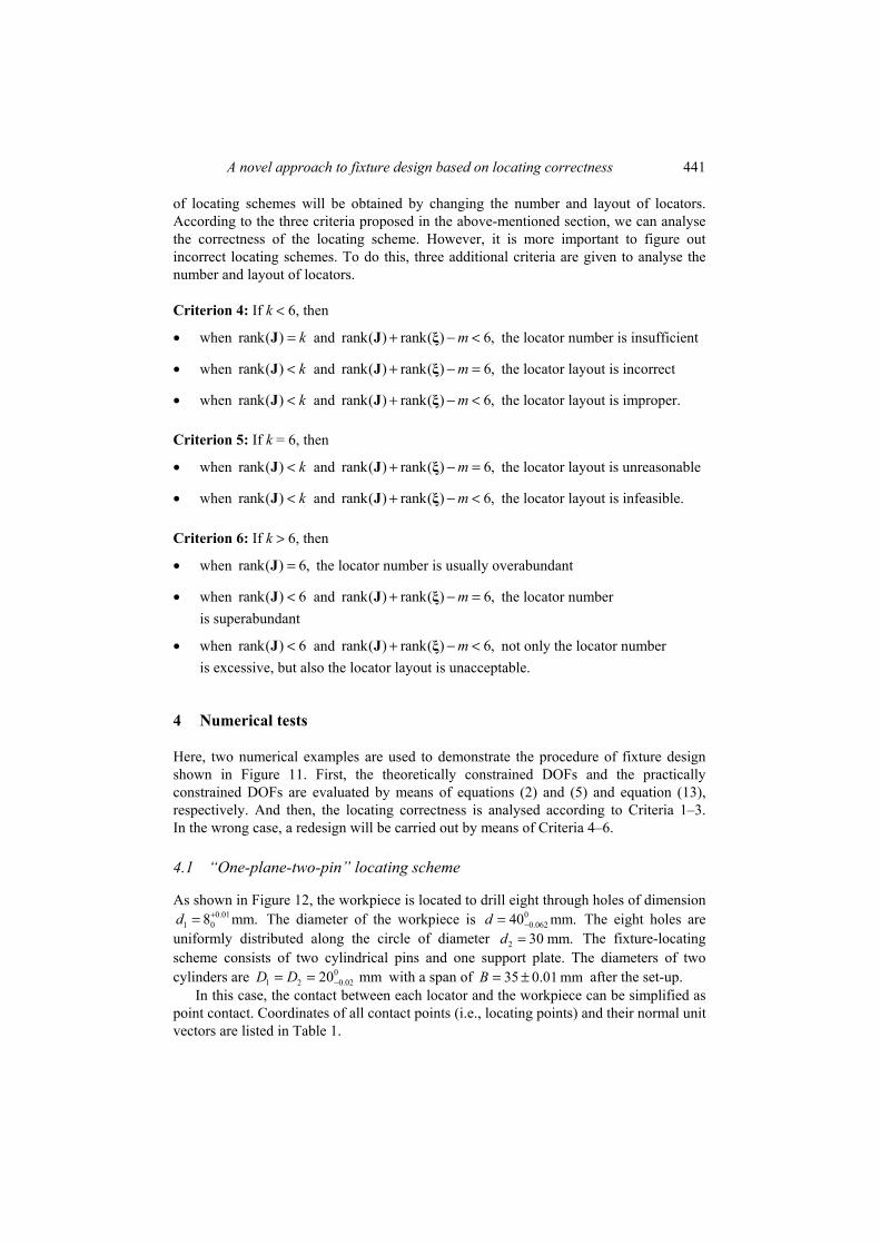
Criterion 4: If k < 6, then
• when rank( ) k=J and rank( ) rank( ) 6,m+ − <J ξ the locator number is insufficient
• when rank( ) k<J and rank( ) rank( ) 6,m+ − =J ξ the locator layout is incorrect
• when rank( ) k<J and rank( ) rank( ) 6,m+ − <J ξ the locator layout is improper.
Criterion 5: If k = 6, then • when rank( ) k<J and rank( ) rank( ) 6,m+ − =J ξ the locator layout is unreasonable
• when rank( ) k<J and rank( ) rank( ) 6,m+ − <J ξ the locator layout is infeasible.
Criterion 6: If k > 6, then • when rank( ) 6,=J the locator number is usually overabundant
• when rank( ) 6<J and rank( ) rank( ) 6,m+ − =J ξ the locator number is superabundant
• when rank( ) 6<J and rank( ) rank( ) 6,m+ − <J ξ not only the locator number is excessive, but also the locator layout is unacceptable.
4 Numerical tests
Here, two numerical examples are used to demonstrate the procedure of fixture design shown in Figure 11. First, the theoretically constrained DOFs and the practically constrained DOFs are evaluated by means of equations (2) and (5) and equation (13), respectively. And then, the locating correctness is analysed according to Criteria 1–3. In the wrong case, a redesign will be carried out by means of Criteria 4–6.
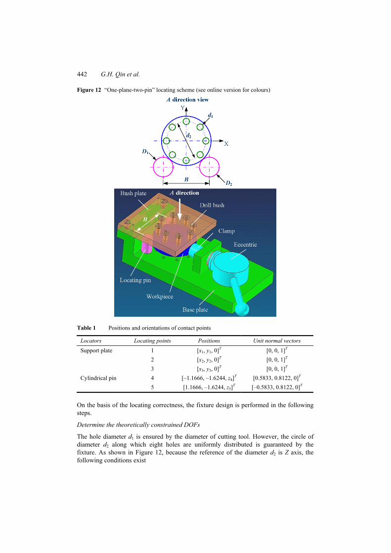
4.1 “One-plane-two-pin” locating scheme
As shown in Figure 12, the workpiece is located to drill eight through holes of dimension 0.01
1 08 mm.d += The diameter of the workpiece is 00.06240 mm.d −= The eight holes are
uniformly distributed along the circle of diameter 2 30 mm.d = The fixture-locating scheme consists of two cylindrical pins and one support plate. The diameters of two cylinders are 0
1 2 0.0220 mmD D −= = with a span of 35 0.01 mmB = ± after the set-up. In this case, the contact between each locator and the workpiece can be simplified as
point contact. Coordinates of all contact points (i.e., locating points) and their normal unit vectors are listed in Table 1.
442 G.H. Qin et al.
Figure 12 “One-plane-two-pin” locating scheme (see online version for colours)
Table 1 Positions and orientations of contact points
Locators Locating points Positions Unit normal vectors
1 [x1, y1, 0]T [0, 0, 1]T 2 [x2, y2, 0]T [0, 0, 1]T
Support plate
3 [x3, y3, 0]T [0, 0, 1]T 4 [–1.1666, –1.6244, z4]T [0.5833, 0.8122, 0]T Cylindrical pin 5 [1.1666, –1.6244, z5]T [–0.5833, 0.8122, 0]T
On the basis of the locating correctness, the fixture design is performed in the following steps.
Determine the theoretically constrained DOFs
The hole diameter d1 is ensured by the diameter of cutting tool. However, the circle of diameter d2 along which eight holes are uniformly distributed is guaranteed by the fixture. As shown in Figure 12, because the reference of the diameter d2 is Z axis, the following conditions exist

A novel approach to fixture design based on locating correctness 443
0.P Px y= = (17)
In addition, because the diameter d2 is in the arbitrary directions, another condition has to hold according to equation (5),
00
P w w P w P
P w w P w P
x x z yy y x z
δ δ δβ δγδ δ δγ δα
= + − = = + − =
(18)
with the arbitrary number .Pz By combining equation (18) with equation (17), the theoretically constrained DOFs
are then obtained as
0.w w w wx yδ δ δα δβ= = = = (19)
Therefore, we have * .w z z γ γδ λ λ= +q ξ ξ (20)
Determine the practically constrained DOFs
The locating Jacobian matrix can be first calculated according to equation (14), i.e.,
1 1
2 2
3 3
4 4
5 5
0 0 1 00 0 1 0
.0 0 1 00.5833 0.8122 0 0.8122 0.5833 0
0.5833 0.8122 0 0.8122 0.5833 0
y xy xy x
z zz z
− − − − = − − − − − − − − −
J (21)
And then, by substituting two bases (ξz and ξγ) into equation (13), the following equations can be derived as
[0,0,1,0,0,0]Tz = ≠Jξ 0 (22)
.γ =Jξ 0 (23)
Obviously, ξz is not a solution of equation (13) so that
1.m = (24)
In fact, when equation (13) is solved, we can determine the practically constrained DOFs as
.w γ γδ λ=q ξ (25)
Analyse the locating correctness
According to equations (19)–(23), we can obtain the following value,
rank( ) rank( ) 5 2 1 6.m+ − = + − =J ξ (26)
As equation (26) belongs to criterion 1, such a locating scheme is hence identified to be a partial location so that it can ensure the machining dimension d2.
444 G.H. Qin et al.
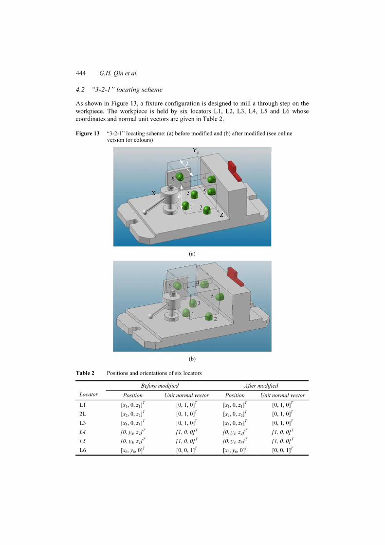
4.2 “3-2-1” locating scheme
As shown in Figure 13, a fixture configuration is designed to mill a through step on the workpiece. The workpiece is held by six locators L1, L2, L3, L4, L5 and L6 whose coordinates and normal unit vectors are given in Table 2.
Figure 13 “3-2-1” locating scheme: (a) before modified and (b) after modified (see online version for colours)
(a)
(b)
Table 2 Positions and orientations of six locators
Before modified After modified Locator Position Unit normal vector Position Unit normal vector L1 [x1, 0, z1]T [0, 1, 0]T [x1, 0, z1]T [0, 1, 0]T 2L [x2, 0, z2]T [0, 1, 0]T [x2, 0, z2]T [0, 1, 0]T L3 [x3, 0, z3]T [0, 1, 0]T [x3, 0, z3]T [0, 1, 0]T L4 [0, y4, z4]T [1, 0, 0]T [0, y4, z4]T [1, 0, 0]T L5 [0, y5, z4]T [1, 0, 0]T [0, y4, z5]T [1, 0, 0]T L6 [x6, y6, 0]T [0, 0, 1]T [x6, y6, 0]T [0, 0, 1]T
A novel approach to fixture design based on locating correctness 445
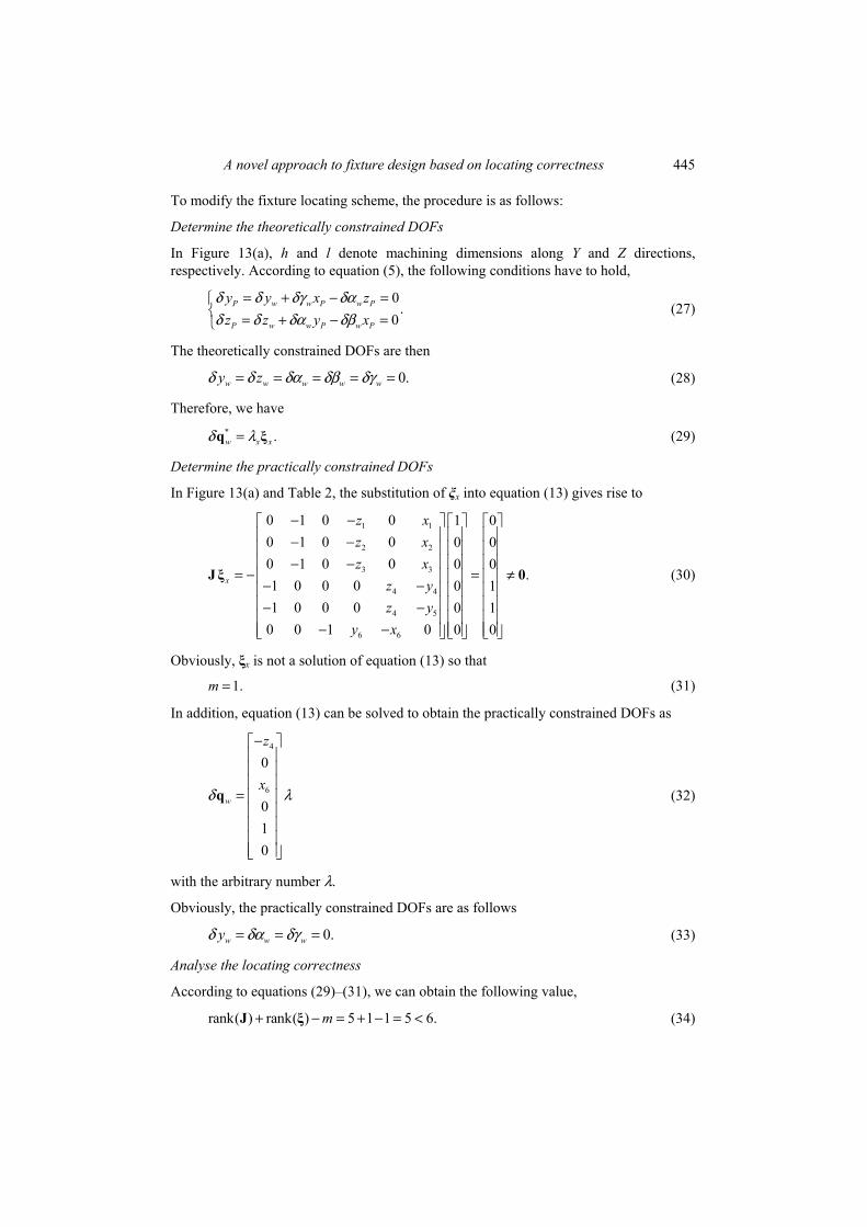
To modify the fixture locating scheme, the procedure is as follows:
Determine the theoretically constrained DOFs
In Figure 13(a), h and l denote machining dimensions along Y and Z directions, respectively. According to equation (5), the following conditions have to hold,
0.
0P w w P w P
P w w P w P
y y x zz z y x
δ δ δγ δαδ δ δα δβ
= + − = = + − =
(27)
The theoretically constrained DOFs are then
0.w w w w wy zδ δ δα δβ δγ= = = = = (28)
Therefore, we have * .w x xδ λ=q ξ (29)
Determine the practically constrained DOFs
In Figure 13(a) and Table 2, the substitution of ξx into equation (13) gives rise to
1 1
2 2
3 3
4 4
4 5
6 6
0 1 0 0 1 00 1 0 0 0 00 1 0 0 0 0
.1 0 0 0 0 11 0 0 0 0 1
0 0 1 0 0 0
x
z xz xz x
z yz y
y x
− − − − − −
= − = ≠ − − − −
− −
J ξ 0 (30)
Obviously, ξx is not a solution of equation (13) so that
1.m = (31)
In addition, equation (13) can be solved to obtain the practically constrained DOFs as
4
6
0
010
w
z
xδ λ
−
=
q (32)
with the arbitrary number λ.
Obviously, the practically constrained DOFs are as follows
0.w w wyδ δα δγ= = = (33)
Analyse the locating correctness
According to equations (29)–(31), we can obtain the following value,
rank( ) rank( ) 5 1 1 5 6.m+ − = + − = <J ξ (34)
446 G.H. Qin et al.
By means of criterion 2, such a locating scheme is identified to be an under over-location, which is an infeasible locating scheme and cannot guarantee the machining dimension l and h of the workpiece.
Modify the incorrect locating scheme
Again, according to criterion 5, we can know that both the locator layout and the number are unreasonable. To obtain the machining dimension l and h, the layout of locators has to be redesigned as that in Figure 13(b) and Table 2. As a result, the following relation can be easily obtained as
rank( ) 6 .k= =J (35)
Finally, the modified locating scheme belongs to an applicable complete location of criterion 2 being able to determine correctly the workpiece position and orientation.
5 Conclusions
A novel locating correctness-based methodology is developed for fixture analysis and design. First, based on the velocity composition law of a particle movement, the DOFs of the workpiece to be essentially constrained are determined following machining requirements. Second, practically constrained DOFs are formulated as a function of the locator number and layout. Finally, quantitative criteria are concluded to capture the relationship between the theoretically constrained DOFs and the practically constrained DOFs. The proposed approach is able to verify the locating correctness and to figure out the cause of locating incorrectness. It provides a practical tool for the development of CAFD system and enriches the quantitative formulation theory of fixture design.
Acknowledgements
This work is supported by Natural Science Foundation of China (Grant No. 10925212), the Aeronautical Science Foundation of China (Grant Nos. 2006ZE56006 and 2008ZE53038), the China Post-Doctor Science Foundation (Grant No. 20070411142), Research Foundation of Aeronautical Support Manufacturing Technology (Grant No. 61901090104), Science and Technology Research Project of Jiangxi Provincial Department of Education (Grant No. 2007-172), and Scientific Research Foundation of Nanchang Hangkong University (Grant No. EA200503139).
References Asada, H. and By, A.B. (1985) ‘Kinematic analysis of workpiece fixturing for flexible assembly
with automatically reconfigurable fixtures’, IEEE Journal of Robotics and Automation, Vol. RA-1, No. 2, pp.86–94.
Cai, W., Hu, S.J. and Yuan, J.X. (1997) ‘A variational method of robust fixture configuration design for 3d workpieces’, Transactions of the ASME Journal of Manufacturing Science and Engineering, Vol. 119, No. 11, pp.593–602.

A novel approach to fixture design based on locating correctness 447
Chou, Y.C., Chandru, V. and Barash, M.M. (1989) ‘A mathematical approach to automatic configuration of machining fixtures: analysis and synthesis’, Transactions of the ASME Journal of Engineering for Industry, Vol. 111, No. 11, pp.299–306.
Hoffman, E.G. (1991) Jig and Fixture Design, Delmar Publishers, Albany, New York. Hong, M., Payandeh, S., Gruver, W.A., Fu, L., Lei, Y.Z. and Zhang, B.P. (1996) ‘Modeling
and analysis of flexible fixturing systems for agile manufacturing’, Proceedings of 1996 IEEE International Conference on Systems, Man and Cybernetics, Beijing, China, October, Vol. 2, pp.1231–1236.
Kang, Y.Z., Rong, Y.M. and Yang, J.C. (2003) ‘Computer-aided fixture design verification. Part 1. The framework and modelling’, International Journal of Advanced Manufacturing Technology, Vol. 21, Nos. 10–11, pp.827–835.
Qin, G.H., Zhang, W.H. and Wan, M. (2006) ‘A mathematical approach to analysis and optimal design of a fixture locating scheme’, International Journal of Advanced Manufacturing Technology, Vo. 29, Nos. 3–4, pp.349–359.
Rong, Y.M. and Zhu, Y.X. (1999) Computer Aided Fixture Design, Marcel Dekker, Basel, New York.
Song, H. and Rong, Y. (2005) ‘Locating completeness evaluation and revision in fixture plan’, Robotics & Computer-Integrated Manufacturing, Vol. 21, Nos. 4–5, pp.368–378.
Trappey, A.J.C. and Liu, C.R. (1992) ‘An automatic workholding verification system’, Robotics & Computer-Integrated Manufacturing, Vol. 9, Nos. 4–5, pp.321–326.
Wang, M.Y. (2002) ‘An optimum design for 3d fixture synthesis in a point set domain’, IEEE Transactions on Robotics and Automation, Vol. 16, No. 6, pp.839–846.
Appendix A: Locating Jacobian matrix
To study the determination of the locating Jacobian matrix, equation (12) is, respectively, differentiated with respect to , , , , andw w w w w wx y z α β γ such that
( , ) ( , ) ( )
( , ) ( , ) ( )
( , ) ( , ) ( )
( , ) ( , ) [ ( ) ]
( , ) ( ,
TTw i w i w
ww i w
TTw i w i w
ww i w
TTw i w i w
ww i w
T Tw i w i w
iw i w
w i w
w
f fx x
f fy y
f fz z
f f
f f
α α
β
∂ ∂ ∂= − ∂ ∂ ∂
∂ ∂ ∂= − ∂ ∂ ∂
∂ ∂ ∂= − ∂ ∂ ∂
∂ ∂ ∂= ∂ ∂ ∂
∂ ∂=
∂
q r q r rT Θr
q r q r rT Θr
q r q r rT Θr
q r q r T Θ rr
q r q
.
) [ ( ) ]
( , ) ( , ) [ ( ) ]
T Ti w
ii w
T Tw i w i w
iw i w
f f
β
γ γ
∂ ∂ ∂ ∂ ∂ ∂
= ∂ ∂ ∂
r T Θ rr
q r q r T Θ rr
(36)
It is known from equation (11) that T(Θw) is a function of αw, βw and γw, the differential of T(Θw) can easily be obtained as
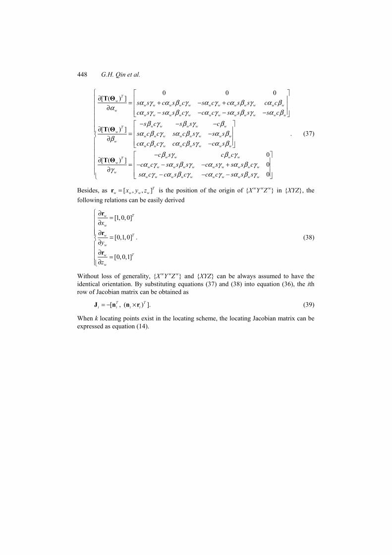
448 G.H. Qin et al.
0 0 0[ ( ) ]
[ ( ) ]
[ (
Tw
w w w w w w w w w w w ww
w w w w w w w w w w w w
w w w w wTw
w w w w w w w ww
w w w w w w w w
s s c s c s c c s s c cc s s s c c c s s s s c
s c s s cs c c s c s s sc c c c c s c s
α γ α β γ α γ α β γ α βα
α γ α β γ α γ α β γ α ββ γ β γ β
α β γ α β γ α ββ
α β γ α β γ α β
∂ = + − + ∂
− − − − − − −
∂ = − ∂ −
∂
T Θ
T Θ
T
.
0) ]
00
w w w wTw
w w w w w w w w w ww
w w w w w w w w w w
c s c cc c s s s c s s s c
s c c s c c c s s s
β γ β γα γ α β γ α γ α β γ
γα γ α β γ α γ α β γ
− = − − − + ∂ − − −
Θ
(37)
Besides, as [ , , ]Tw w w wx y z=r is the position of the origin of {X
wY wZ
w} in {XYZ}, the following relations can be easily derived
[1,0,0]
[0,1,0] .
[0,0,1]
Tw
w
Tw
w
Tw
w
x
y
z
∂=∂
∂ =∂∂
=∂
r
r
r
(38)
Without loss of generality, {X wY
wZ w} and {XYZ} can be always assumed to have the
identical orientation. By substituting equations (37) and (38) into equation (36), the ith row of Jacobian matrix can be obtained as
[ , ( ) ].T Ti i i i= − ×J n n r (39)
When k locating points exist in the locating scheme, the locating Jacobian matrix can be expressed as equation (14).