Embed Size (px)
Citation preview
A Note on Polymeric Inner-Layered Single Fiber Interfacial Strength Determination
RAJU DAVE and LUIS LOREN20
Polymer Technology Center Michigan Molecular Institute
Midland, Michigan 48640
The role of inner-layer (interphase) in fiber-reinforced composites is often assessed by measuring the interfacial shear strength of single fibers embedded in matrix blocks. Interfacial shear strength is calculated using simple shear lag analyses (Kelly and Tyson model). This paper shows that application of Kelly and Tyson’s equation may result in gross overprediction of interfacial shear strengths if the thickness of the inner-layer is not negligible in comparison with the fiber diameter.
INTRODUCTION
o assess the mechanical performance of compos- T ites, it is necessary to establish how effective the adhesion between fibers and resins is. Single fibers embedded in matrix blocks have been used in the past for measuring the interfacial shear strength of fibers in composites as a method for quantifying adhesion.
Assuming that the interface between fiber and matrix fails by yielding and plastic flow, Kelly and Tyson (1) showed that the interfacial shear strength is given by
where d and q a r e the fiber diameter and fiber tensile strength, respectively. The parameter 2, is called the critical fiber length. 1,/2 is the distance from a fiber end over which the fiber stress builds up to u ~ , the undisturbed fiber stress (Fig. 1 ).
Experimentally, 1, can be measured and an average interfacial shear strength calculated according to E q 1. The technique has evolved following the work by Fraser, et al. (2) and has lately been extensively applied by Drzal and coworkers (3-7) for identifica- tion of failure mechanisms and characterization of fiber surfaces.
An implicit requirement for applying Eq 1 to pre- dict T by measuring 1, is that the locus of yield failure exists between the fiber and the inner-layer (if there is an inner-layer) or between the fiber and the resin matrix (if no inner-layer is present). However, it is evident from some reported studies (8-10) that the above criterion may not have been satisfied, and yet E q 1 was used for the prediction of r . For example, Folkes and Wong (8) used E q 1 to determine the
interfacial strength between glass fiber and thermo- plastics, i.e., polyethylene. They observed a trans- crystalline sheath around the glass fiber. The thick- ness of the transcrystalline sheath was of the order of the diameter of the fiber. In general, transcrystal- line morphology leads to a poor bonding as reported by Bessel, et al. (1 1). Therefore, there is strong like- lihood that the locus of failure around the single fiber was between the transcrystalline sheath and the matrix rather than the fiber and the transcrystalline sheath. This possibility has been also suggested by Folkes and Wong (8).
Another example where a similar situation may have occurred is in the study by Crasto, et aZ. (9, 10). The authors applied Eq 1 to predict the interfacial shear strength of an inner-layered graphite fiber composite (1 0). Figure 2, from Rej. 9, shows a SEM micrograph of the failure surfaces of interlaminar shear strength specimens made with electrocoated poly(butadiene-co-maleic anhydride) [BMA] carbon filaments. It is evident from Fig. 2 that failure in the specimens has occurred between the inner-layer and the matrix.
This note presents a modification to Kelly and Tyson shear lag analysis by incorporating the effect of an inner-layer. I t is shown that if failure in an inner-layered single-fiber composite occurs between the inner-layer and the matrix, Eq 1 overpredicts T .
ANALYSIS AND DISCUSSION
Consider an inner-layer coated single fiber em- bedded in an infinite matrix (Fig. 3) . It is assumed that upon fiber fracture, the interface between the inner-layer and the matrix fails by yielding and plas- tic flow. Denoting by uf and ut the undisturbed fiber stress and inner layer stress, respectively, at a dis- tance l ,/2 from the fiber end, equilibrium of the fiber
POLYMER COMPOSITES, JUNE 1989, Vol. 10, No. 3 199
R. Dave and L. Lorenzo
- 1 I < I ,
- 1 I = I ,
- 1 I > lC
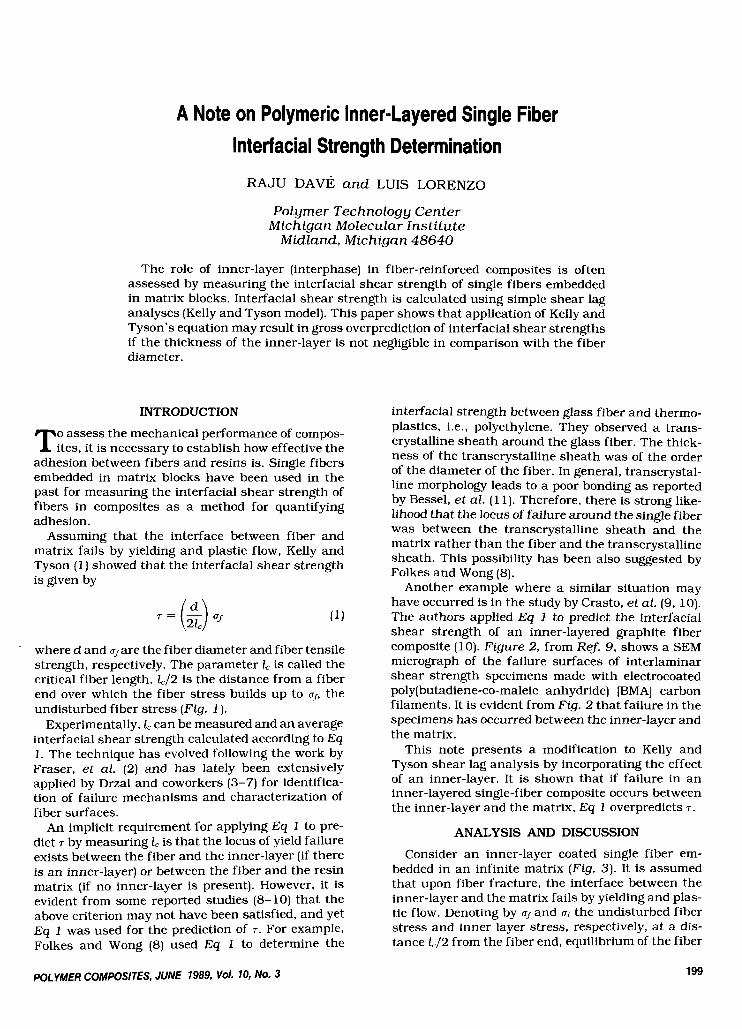
Fig. 1 . Simplified stress distribution inside discrete fibers of different lengths. I , is the critical fiber length. A rigid perfectly plastic behavior is assumed at the interface.
Fig. 3. Simplified stress distribution outside and inside a broken fiber coated with an inner-layer. A rigid per- fec t ly plastic behavior is assumed at the interface be- tween the inner-layer and the matrix.
layer and the matrix. On simplification, Eq 2 reduces to
Fig. 2. SEM micrographs of the failure surfaces of inter- laminar shear strength specimens made with electro- coated polylbutadiene-co-maleic anhydride) [BMAJ. [Courtesy of Dr. R. V. Subramanian; reprinted with per- mission of Polymer Composites (91.1
end gives
where tl is the thickness of the inner-layer and r1 is the interfacial yield shear stress between the inner-
Note that in general for a single fiber coated with a polymeric inner-layer, matrix and inner-layer moduli are of the same order of magnitude; that is,
Em El. (4)
Thus, for the undisturbed fiber under a condition of uniform axial strain eo, the axial strains in the con- stituents are related by
to = tf = em = e l .
Since E, >> Em for glass, graphite, and polymeric fibers (see Table 1 from ReJ. 12), it follows that
(5)
Furthermore, taking into account that t l < dfor tt and d, are of the same order of magnitude, Eq 3 reduces to
r 1
Equation 7 shows that when the locus of interfa-
200 POLYMER COMPOSITES, JUNE 1989, Vol. 10, No. 3
A Note on Polymeric Inner-Layered Single Fiber Interfacial Strength Determination
Table 1. Typical Material Properties of Constituents of Fiber Composites (from Ref. 12).
Material
Matrix" Fiber
Epoxy Graphite Property (IMHS)b Kevlar Glass"
Longitudinal Modulus EL, 3.42 220 150 72
Transverse modulus ET, 3.42 13.7 4.1 72
Longitudinal Poisson's 0.35 0.2 0.35 0.22
Transverse Poisson's 0.35 0.25 0.35 0.22
Longitudinal shear 1.3 8.8 2.9 30
Transverse shear 1.3 4.8 1.5 30
GPa
GPa
ratio uI2
ratio u j 2
modulus GL, GPa
modulus GT, GPa
Isotropic material. IMHS = intermediate modulus high strength.
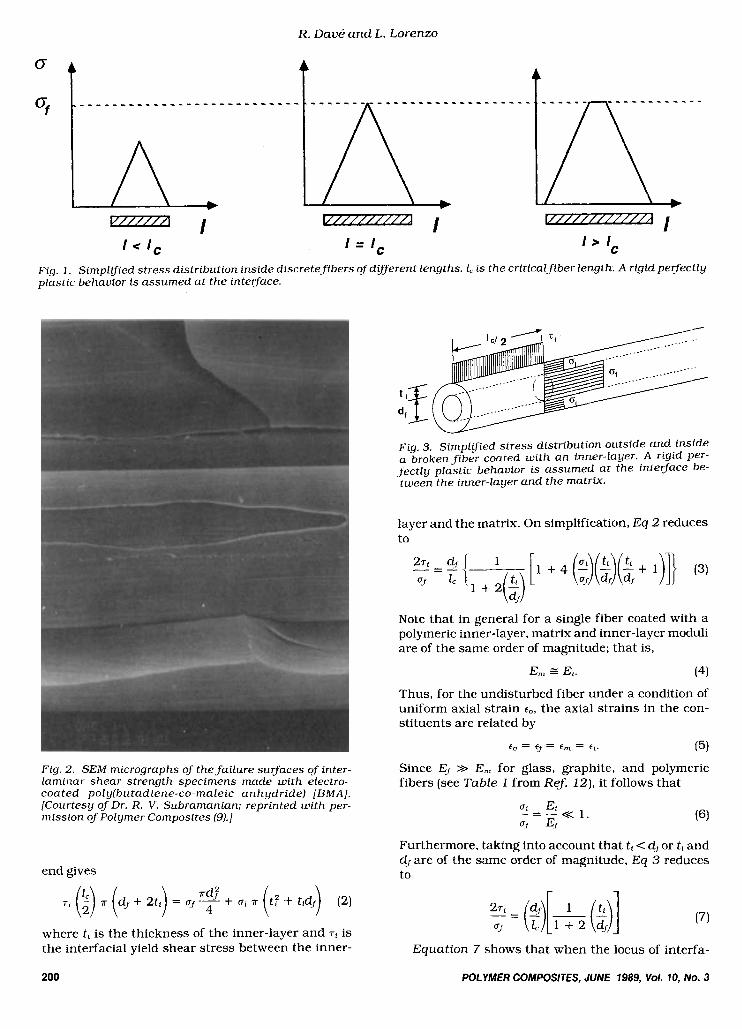
cia1 failure is between the inner-layer and the matrix, a correction factor
r 1-1
t = 11 + 2 ($1 has to be introduced for computing the interfacial shear strength. The variation oft with (t , /df) is shown in Fig. 4. Note that if the locus of failure is between the fiber and the inner-layer or the thickness of the inner-layer is negligible, i.e., tt = 0, then t = 1 and Eq 7 reduces to Eq 1. On the other hand, if the locus of failure is indeed between the inner-layer and the matrix and if Eq 1 is used to predict T , the predicted value is overpredicted in comparison with the true interfacial strength.
Finally, a few general points that have to do with the results of the analysis now follow. The objective of this paper was primarily to caution readers regard- ing the use of Kelly-Tyson equation for the prediction of interfacial shear strength of polymer-coated single fibers. If the coating thickness is 0.5-2 wm, then the correction factor t will be 0.87-0.64 for graphite fiber, 0.94-0.80 for glass fiber, and 0.92-0.75 for Kevlar fiber [see Table 2). Such deviation in the measurement of the interfacial strength cannot be considered inconsequential.
CONCLUSIONS
The use of simple shear lag analyses for the exper- imental determination of interfacial shear strengths must rely on the correlation between the theoretical assumptions and the failure modes activated during failure of the specimen. It was shown that the appli- cation of Kelly and Tyson's equation may result in gross overprediction of interfacial shear strengths. Monitoring of the accumulation of individual failure mechanisms is required to ascertain that the under- lying theoretical hypothesis is not violated.
1
+ 2( "h)
1 .o
0.8
0.6
0.4
0.2
0.0 0.2 0.4 0.6 0.8 1 .o
( V 4 )
Fig. 4 . Effect of thickness of the inner-layer on the cor- rection fac tor e . The correction fac tor e predicts the over- prediction in the T value in comparison w i t h the true interfacial strength.
Table 2. Correction Factor t for Polymeric Inner-layered Single Fiber Strength Measurements.
Thickness of
Diameter Inner-layer Correction Fiber (Pm) (Pm) Factor t
0.87-0.64 Graphite 7 0.5-2 Glass 16 0.5-2 0.94-0.80 Kevlar 12 0.5-2 0.92-0.75
ACKNOWLEDGMENTS
The authors would like to thank Dr. R. V. Subra- manian of Washington State University for his help- ful comments and providing us with an original copy of Fig. 2.
REFERENCES
1. A. Kelly and W. R. Tyson, J . Mech. Phys. Solids, 13, 329 (1965).
2. W. A. Fraser, F. H. Achker, and A. T. DiBenedetto, Proc. 30th Annu. Tech. Conf., RP/CI, SPI, 22-A, 1 (1975).
3. L. T. Drzal, M. J. Rich, J. D. Camping, and W. J. Park, Proc. 35th Annu. Tech. Conf., RP/CI, SPI, 20-C, 1 (1980).
4 . L. T. Drzal, M. J. Rich, J. D. Camping, and W. J. Park, "Interfacial Shear Strength and Failure Mechanisms i n Graphite Fiber Composites," AFWAL-TR-8 1-4003 (1981).
5. L. T. Drzal, Proc. 15th National SAMPE Tech. Conf., 190 (1983).
6. L. T. Drzal, Proc. 28th National SAMPE Symposium, 1057 (1983).
7. M. J. Rich and L. T. Drzal, J. Reinf. Plast . Cornpos., 7. 145 (1988).
8. M. J. Folkes and W. K. Wong, Polymer, 28. 1309 (1987). 9. A. S. Crasto and R. V. Subramanian, Polyrn. Cornpos.,
7 , 201 (1986). 10. A. S. Crasto, S. H. Own, and R. V. Subramanian, Polyrn.
Cornpos., 9, 78 (1988). 11. T. Bessell, D. Hull, and J . B. Shortall, Faraday Spec.
Disc. , Chern. SOC., 2 , 137 (1972). 12. C. C. Chamis, ModernPZastics, 156 (June 1986).
POLYMER COMPOSITES, JUNE 1989, Vol. 70, No. 3 201

![1 Interfacial Rheology System. 2 Background of Interfacial Rheology Interfacial Shear Stress Interfacial Shear Viscosity = [ ]](https://img.pdfslide.us/doc/110x75/56649d1f5503460f949f3d29/1-interfacial-rheology-system-2-background-of-interfacial-rheology-interfacial.jpg)