Embed Size (px)
Citation preview
A new scroll-type air motor with magnetic spirals
LUO, Xing, WANG, Jihong, SHPANIN, Leon <http://orcid.org/0000-0002-3085-4678> and DOONER, Mark
Available from Sheffield Hallam University Research Archive (SHURA) at:
http://shura.shu.ac.uk/22666/
This document is the author deposited version. You are advised to consult the publisher's version if you wish to cite from it.
Published version
LUO, Xing, WANG, Jihong, SHPANIN, Leon and DOONER, Mark (2018). A new scroll-type air motor with magnetic spirals. IEEE/ASME transactions on mechatronics, 23 (1), 459-468.
Copyright and re-use policy
See http://shura.shu.ac.uk/information.html
Sheffield Hallam University Research Archivehttp://shura.shu.ac.uk

IEEE/ASME TRANSACTIONS ON MECHATRONICS, VOL. 23, NO. 1, FEBRUARY 2018 459
A New Scroll-Type Air Motor WithMagnetic Spirals
Xing Luo, Jihong Wang , Senior Member, IEEE, Leonid Shpanin , Member, IEEE, and Mark Dooner
Abstract—The scroll-type air motor, also named the scrollexpander, has been widely used for different applicationsdue to its characteristics of compact structure and high en-ergy conversion efficiency. However, the leakage and thefriction result in non-negligible energy losses. This paperpresents the recent work on developing a new scroll-typeair motor with mounted permanent magnetic spirals and in-vestigates its potential in leakage reduction and efficiencyimprovement, especially at low-pressure air supply con-ditions. A method for the implementation of the magneticscroll air motor is proposed. A prototype is manufactured,and initial experimental tests are conducted to study thegeneralized torque distribution. A mathematical model forthe magnetic scroll air motor is developed, and a corre-sponding simulation study is presented. The study showsthat the proposed magnetic scroll air motor structure is fea-sible in terms of manufacturing and has the potential toreduce the air leakage and, thus, to improve the energy ef-ficiency by a maximum of around 15% at a supply pressureof 2 × 10⁵ Pa, with a flank leakage clearance reference of0.06 mm.
Index Terms—Energy efficiency, magnetic, mathematicalmodeling, prime mover of generator, scroll-type air motor.
I. INTRODUCTION
PNEUMATIC motors convert compressed air energy intodriving force for linear and angular motions, and their ap-
plications can be found in industrial and residential areas. Thepaper will focus on one particular type—the scroll-type air mo-tor (also named the scroll expander), and it will propose a newdesign for improving its performance and energy efficiency.
The scroll technology has been widely applied in the com-pressors of air conditioners (e.g., residual and automotive airconditioning), refrigerators, and auxiliaries in different systems
Manuscript received February 13, 2017; revised July 18, 2017; ac-cepted August 27, 2017. Date of publication November 17, 2017; date ofcurrent version February 14, 2018. Recommended by Technical EditorY. Shtessel. This work was supported by the Engineering and PhysicalSciences Research Council (EPSRC), U.K., under Grant EP/K002228/1and Grant EP/L019469/1, and by the China 973 Research Programmeunder Grant 2015CB251301. (Corresponding author: Jihong Wang.)
X. Luo, J. Wang, and M. Dooner are with the School of Engineer-ing, University of Warwick, Coventry, CV4 7AL, U.K. (e-mail: [email protected]; [email protected]; [email protected]).
L. Shpanin is with the Faculty of Engineering, Environment, and Com-puting, Coventry University, Coventry, CV1 5FB, U.K. (e-mail: [email protected]).
Color versions of one or more of the figures in this paper are availableonline at http://ieeexplore.ieee.org.
Digital Object Identifier 10.1109/TMECH.2017.2749378
(e.g., superchargers for vehicle engines and some optical equip-ment) [1], [2]. The technology has recently been extended formanufacturing pneumatic motors (expanders) [3]–[5]. Inheritedfrom the structure of scroll compressors, scroll-type air motorshave distinguished merits, including compact design, operationreliability, low level of noise, and relatively high energy conver-sion ability at a certain range of working conditions [3]–[7].
The study of scroll-type air motors and scroll expansionequipment using different working mediums have been exploredin both academia and industry, mainly focusing on the optimiza-tion study of the scroll geometry and the working process forimproving the device’s performance and efficiency, the applica-tions of the scroll technology for recycling exhaust energy withlow-pressure and/or low-grade heat characteristics, as a primemover for electricity generators, and as a key energy conversionunit for small-scale energy storage through fuel cells and com-pressed air. A literature review of the recent progress on thisarea is presented later.
Concerning mathematical modeling and optimization, amathematical description of a method to design a scroll-typeair motor with variable wall thickness was developed by Wanget al. and Dickes in [8] and [9], respectively. An optimizedvolumetric (or expansion) ratio can be achieved by their devel-oped models and the isentropic efficiency could be improved[8], [9]. A complete dynamic model for scroll air motors withvalidation was presented in [5]. The energy efficiency analysiswas also performed, which explained the scroll’s good ability inenergy conversion [5]. The unsteady flow losses with vortexesin the suction process of the scroll expander have been studiedvia a three-dimensional transient computational fluid dynamic(CFD) numerical model, which can provide guidance for theoptimal design of the suction port of scroll mechanism [10].In the area of energy recovery, the performance of a scroll ex-pander used for recovering the exhausted air from a fuel cellsystem was studied in [11]. The paper indicates that the leakagehas a significant effect on the volumetric efficiency of the sys-tem. A hybrid pneumatic system that recovers energy from theexhaust air through a scroll expander was designed by Luo etal., which concluded that, with a proper closed-loop coordinatecontrol strategy, the energy efficiency improvement can reach18.1% from the tests [12]. Luo et al. also studied a vehicle gaso-line engine post-combustion mixture energy reusing system viathe scroll technology [13]. The strategies for modification ofthe scroll expander were investigated and the simulation resultsindicated that it is possible to produce hundreds of Watts ofpower output from energy recycling, with over 90% of exhaust
This work is licensed under a Creative Commons Attribution 3.0 License. For more information, see http://creativecommons.org/licenses/by/3.0/
460 IEEE/ASME TRANSACTIONS ON MECHATRONICS, VOL. 23, NO. 1, FEBRUARY 2018
flow being recycled [13]. The Organic Rankine Cycle (ORC)system is one of the most important application areas of scrollexpanders. Song et al. reviewed the research in this area, in-cluding the prototypes of scroll expanders for ORC systems,theoretical modeling and CFD simulation in scroll machine de-sign [7]. The leakage with clearances of scroll expanders is oneof focuses in [7]. For small-scale Compressed Air Energy Stor-age (CAES) systems, Krupke et al. studied a scroll air motorwithin a small-scale CAES system to support wind power gen-eration and integration [14]. The study demonstrates the benefitof improved efficiency with optimized tip speed ratio broughtto the hybrid wind turbine operation [14].
In industry, the U.K.-based company Flowgroup (previouslynamed FlowBattery and Energetix Group) commercialized theCompressed Air Battery (CAB) which can be considered as avariant of the small-scale CAES facility. It has been used inU.K. and U.S. national grids and data centers for uninterruptedpower supply (UPS) [15]. The company has also released themicro combined heat and electrical power (CHP) system. It isclaimed that people could save 20% of gas and electricity billsby using such type of CHP system at home [16]. The scroll airmotor (expander) has been used as a core component in the twoproducts for efficient multi-energy conversion [15], [16]. TheUS-based company Airsquared is a pioneer in the manufactureof scroll expanders [17]. The company has studied the com-bined scroll expansion–compression in hydrogen recirculationand many other scroll-relevant projects [17].
From the previous literature review, it can be found that,in many of the earlier designs/applications, scroll air motors(expanders) have been used as a prime mover to produce thedriving torque for electrical generators [7], [12]–[17].
From the authors’ previous study and the literature review, itis noticed that the energy conversion ability of scroll air motorsis reduced when the supply air pressure is low [4], [5], [7], [11].This is mainly caused by the air leakage between the chambersand the frictions. Such a characteristic will undoubtedly affectand limit many applications of scroll air motors, especially inlow-pressure exhaust energy recycling and small-scale energystorage systems. To address this issue, the paper presents an in-novative design by inserting permanent magnetic materials intothe original fixed and moving scrolls to change the distributionof the acting forces/torques. It is expected that the developedmagnetic scroll air motor has the potential to reduce the leakageand, in turn, improve the efficiency.
The paper begins with the description of the implementationof the proposed design. The magnetic field distribution and theflux density magnitude are studied via finite element simulation.An experimental study of the effect of the magnets is conductedusing a prototype. A mathematical model for the design is thendeveloped based on the model for ordinary scroll air motors.From the study, the potential benefits on the air leakage and theenergy efficiency are justified.
II. DESCRIPTION OF THE NEW MAGNETIC SCROLL
This section presents the principle of magnetic scroll air mo-tors, the selection and the installation of magnetic materials, andthe magnetization of magnetizable spiral segments.
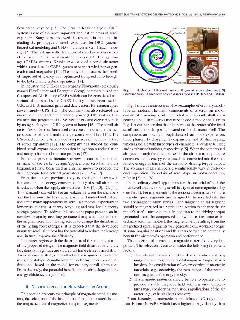
Fig. 1. Illustration of the ordinary scroll-type air motor structure [13](modified from Sanden scroll compressors, types: TRSA05 and TRS09).
Fig. 1 shows the structures of two examples of ordinary scroll-type air motors. The main components of a scroll air motorconsist of a moving scroll connected with a crank shaft via abearing and a fixed scroll mounted inside a motor shell. FromFig. 1, it can be seen that the inlet port is at the center of the fixedscroll and the outlet port is located on the air motor shell. Thecompressed air flowing through the scroll air motor experiencesthree phases: 1) charging; 2) expansion; and 3) discharging,which associate with three types of chambers: a) central; b) side;and c) exhaust chambers, respectively [5]. When the compressedair goes through the three phases in the air motor, its pressuredecreases and its energy is released and converted into the shaftkinetic energy in terms of the air motor driving torque output.The volumes of all chambers discontinuously vary in cycle-to-cycle operation. For details of scroll-type air motor operation,refer to [5] and [8].
In an ordinary scroll-type air motor, the material of both thefixed scroll and the moving scroll is a type of nonmagnetic alloy(see Fig. 1). For implementing the proposed design, two or moremagnetic spiral segments are designed to be inserted into thetwo nonmagnetic alloy scrolls. Each magnetic spiral segmentshould be magnetized in a particular direction to enhance the airmotor’s useful torque output. In addition to the driving torquegenerated from the compressed air (which is the same as forordinary scroll air motors), the magnetic field resulting from themagnetized spiral segments will generate extra workable torqueat some angular positions and this extra torque can potentiallybenefit the air motor’s operation and performance.
The selection of permanent magnetic materials is very im-portant. The selection needs to consider the following importantfactors.
1) The selected materials must be able to produce a strongmagnetic field to generate useful magnetic torque, whichinvolves the consideration of key properties of magneticmaterials, e.g., coercivity, the remanence of the perma-nent magnet, and energy density.
2) The magnetic materials should be able to operate and toprovide a stable magnetic field within a wide tempera-ture range, considering the various applications of the airmotor, e.g., exhaust (heat) recovery.
From the study, the magnetic material chosen is Neodymium–Iron–Boron (NdFeB), which has a higher energy density than
LUO et al.: NEW SCROLL-TYPE AIR MOTOR WITH MAGNETIC SPIRALS 461
TABLE ICOMPARISON OF PROPERTIES OF VACODYM 655 HR & 722 HR AT
20 °C [18]
Typical Values of Magnetic- VACODYM VACODYMRelated Properties 655 HR 722 HR
Remanence Br 1.28 T 1.47TEnergy density (BH )m ax 315 kJ/m3 415 kJ/m3
Coercivity HcB 990 kA/m 915 kA/mInner magnetizing field strength Hm ag 2500 kA/m 2500 kA/mMaximum continuous temperature Tm ax 150 oC 50 oC
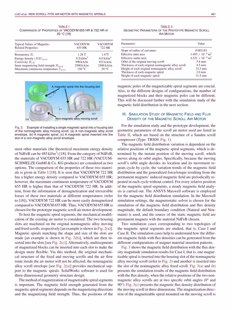
Fig. 2. Example of installing a single magnetic spiral into a housing slotof the nonmagnetic alloy moving scroll. (a) A non-magnetic alloy scrollenvelope. (b) A magnetic spiral. (c) A magnetic spiral inserted into theslot of a non-magnetic alloy scroll envelope.
most other materials (the theoretical maximum energy densityof NdFeB can be 485 kJ/m3) [18]. From the category of NdFeB,the materials of VACODYM 655 HR and 722 HR (VACUUM-SCHMELZE GmbH & Co. KG products) are considered as twooptions. The comparison of the properties of these two materi-als is given in Table I [18]. It is seen that VACODYM 722 HRhas a higher energy density compared to VACODYM 655 HR;however, the maximum continuous temperature of VACODYM655 HR is higher than that of VACODYM 722 HR. In addi-tion, from the information of demagnetization and irreversiblelosses of these two materials at different temperatures (referto [18]), VACODYM 722 HR can be more easily demagnetizedcompared to VACODYM 655 HR. Thus, VACODYM 655 HR ischosen for the prototype magnetic scroll air motor development.
To host the magnetic spiral segments, the mechanical modifi-cation of the existing air motor is considered. The two housingslots are machined on the original nonmagnetic alloy movingand fixed scrolls, respectively [an example is shown in Fig. 2(a)].Magnetic spirals matching the shape and size of the slots aremade [an example is shown in Fig. 2(b)], which are then in-serted into the slots [see Fig. 2(c)]. Alternatively, multisegmentsof magnetized blocks can be inserted into each slot to make thedesign more flexible. Via this method, the original mechani-cal structure of the fixed and moving scrolls and the air flowroute inside the air motor will not be affected; the nonmagneticalloy scroll envelope [see Fig. 2(a)] provides mechanical sup-port to the magnetic spirals. SolidWorks software is used forthree-dimensional geometry structure design.
The method of magnetization of magnetizable spiral segmentsis important. The magnetic field strength generated from themagnetic spiral segments depends on the magnetizing directionsand the magnetizing field strength. Thus, the positions of the
TABLE IIGEOMETRIC PARAMETERS OF THE PROTOTYPE MAGNETIC SCROLL
AIR MOTOR
Parameters Value
Slope of radius of curvature 0.003183Effective inlet area 1.493 × 10⁻⁴ m2
Effective outlet area 4.531 × 10⁻⁴ m2
Orbit of the original moving scroll 5.8 mmThickness of each original nonmagnetic alloy scroll 4.5 mmHeight of each original nonmagnetic alloy scroll 33.3 mmThickness of each magnetic spiral 2.0 mmHeight of each magnetic spiral 31.5 mm
magnetic poles of the magnetizable spiral segments are crucial.Also, to the different designs of configurations, the number ofmagnetized blocks and their magnetic poles can be different.This will be discussed further with the simulation study of themagnetic field distribution in the next section.
III. SIMULATION STUDY OF MAGNETIC FIELD AND FLUX
DENSITY OF THE MAGNETIC SCROLL AIR MOTOR
For the simulation study and the prototype development, thegeometric parameters of the scroll air motor used are listed inTable II, which are based on the structure of a Sanden scrollcompressor (Type: TRS09, Fig. 1).
The magnetic field distribution variation is dependent on therelative positions of the magnetic spiral segments, which is de-termined by the instant position of the moving scroll, whichmoves along its orbit angles. Specifically, because the movingscroll’s orbit angle decides its location and its movement re-peats cycle by cycle, the variation trends of the magnetic fielddistribution and the generalized force/torque resulting from thepermanent magnets’ induced magnetic field are periodically re-peated in each cycle without control. For every relative positionof the magnetic spiral segments, a steady magnetic field analy-sis is carried out. The ANSYS Maxwell software is employedfor the magnetic field distribution simulation. In the Maxwellsimulation settings, the magnetostatic solver is chosen for thesimulation of the magnetic field distribution and flux densitymagnitude, the default boundary condition (Natural and Neu-mann) is used, and the source of the static magnetic field arepermanent magnets with the material NdFeB chosen.
Two simulation cases corresponding to two topologies ofthe magnetic spiral segments are studied, that is, Case I andCase II. The simulation cases help to understand how the differ-ent magnetic fields with flux densities can be generated from thedifferent configurations of magnet material insertion patterns.
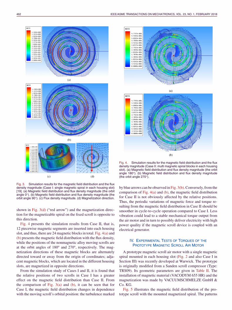
Fig. 3 shows the magnetic field distribution with the flux den-sity magnitude simulation results for Case I, that is, one magne-tizable spiral is inserted into the housing slot of the nonmagneticalloy moving scroll (refer to Fig. 2) and another is inserted intothe slot of the nonmagnetic alloy fixed scroll. Fig. 3(a) and (b)presents the simulation results of the magnetic field distributionwith the flux density, when the relative positions of the two non-magnetic alloy scrolls are at two specific orbit angles (0o and90o). Fig. 3(c) presents the magnetic flux density distribution ofthe moving scroll in three dimensions. The magnetization direc-tion of the magnetizable spiral mounted on the moving scroll is
462 IEEE/ASME TRANSACTIONS ON MECHATRONICS, VOL. 23, NO. 1, FEBRUARY 2018
Fig. 3. Simulation results for the magnetic field distribution and the fluxdensity magnitude (Case I: single magnetic spiral in each housing slot)[19]. (a) Magnetic field distribution and flux density magnitude (the orbitangle 0°). (b) Magnetic field distribution and flux density magnitude (theorbit angle 90°). (c) Flux density magnitude. (d) Magnetization direction.
shown in Fig. 3(d) (“red arrow”) and the magnetization direc-tion for the magnetizable spiral on the fixed scroll is opposite tothis direction.
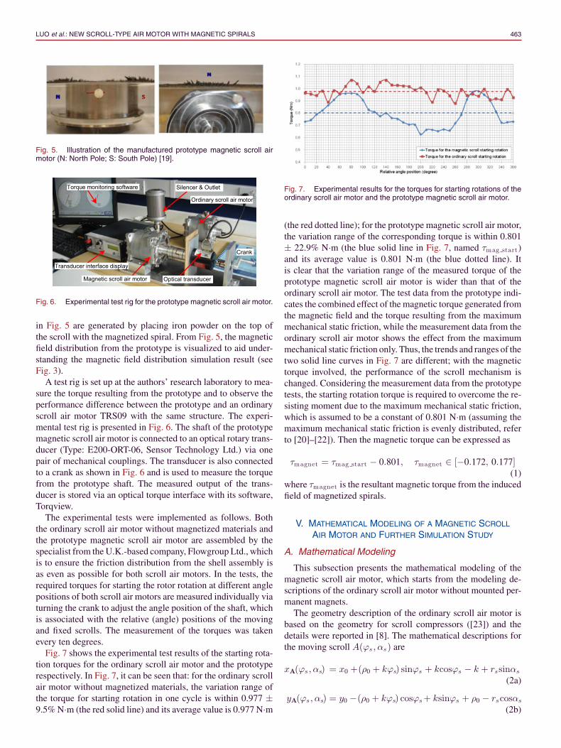
Fig. 4 presents the simulation results from Case II, that is,12 piecewise magnetic segments are inserted into each housingslot, and thus, there are 24 magnetic blocks in total. Fig. 4(a) and(b) presents the magnetic field distribution with the flux density,while the positions of the nonmagnetic alloy moving scrolls areat the orbit angles of 180o and 270o, respectively. The mag-netization directions of these magnetic blocks are alternatelydirected toward or away from the origin of coordinates; adja-cent magnetic blocks, which are located in the different housingslots, are magnetized in opposite directions.
From the simulation study of Cases I and II, it is found thatthe relative positions of two scrolls in Case I has a greatereffect on the magnetic field distribution than Case II. Fromthe comparison of Fig. 3(a) and (b), it can be seen that forCase I, the magnetic field distribution changes in dependencewith the moving scroll’s orbital position: the turbulence marked
Fig. 4. Simulation results for the magnetic field distribution and the fluxdensity magnitude (Case II: multi magnetic spiral blocks in each housingslot). (a) Magnetic field distribution and flux density magnitude (the orbitangle 180°). (b) Magnetic field distribution and flux density magnitude(the orbit angle 270°).
by blue arrows can be observed in Fig. 3(b). Conversely, from thecomparison of Fig. 4(a) and (b), the magnetic field distributionfor Case II is not obviously affected by the relative positions.Thus, the periodic variations of magnetic force and torque re-sulting from the magnetic field distribution in Case II should besmoother in cycle-to-cycle operation compared to Case I. Lessvibration could lead to a stable mechanical torque output fromthe air motor and in turn to possibly deliver electricity with highpower quality if the magnetic scroll device is coupled with anelectrical generator.
IV. EXPERIMENTAL TESTS OF TORQUES OF THE
PROTOTYPE MAGNETIC SCROLL AIR MOTOR
A prototype magnetic scroll air motor with a single magneticspiral mounted in each housing slot (Fig. 2 and also Case I inSection III) was recently developed at Warwick. The prototypeis originally modified from a Sanden scroll compressor (Type:TRS09). Its geometric parameters are given in Table II. Theinstallation of magnetic material (VACODYM 655 HR) and themagnetization was made by VACUUMSCHMELZE GmbH &Co. KG.
Fig. 5 illustrates the magnetic field distribution of the pro-totype scroll with the mounted magnetized spiral. The patterns
LUO et al.: NEW SCROLL-TYPE AIR MOTOR WITH MAGNETIC SPIRALS 463
Fig. 5. Illustration of the manufactured prototype magnetic scroll airmotor (N: North Pole; S: South Pole) [19].
Fig. 6. Experimental test rig for the prototype magnetic scroll air motor.
in Fig. 5 are generated by placing iron powder on the top ofthe scroll with the magnetized spiral. From Fig. 5, the magneticfield distribution from the prototype is visualized to aid under-standing the magnetic field distribution simulation result (seeFig. 3).
A test rig is set up at the authors’ research laboratory to mea-sure the torque resulting from the prototype and to observe theperformance difference between the prototype and an ordinaryscroll air motor TRS09 with the same structure. The experi-mental test rig is presented in Fig. 6. The shaft of the prototypemagnetic scroll air motor is connected to an optical rotary trans-ducer (Type: E200-ORT-06, Sensor Technology Ltd.) via onepair of mechanical couplings. The transducer is also connectedto a crank as shown in Fig. 6 and is used to measure the torquefrom the prototype shaft. The measured output of the trans-ducer is stored via an optical torque interface with its software,Torqview.
The experimental tests were implemented as follows. Boththe ordinary scroll air motor without magnetized materials andthe prototype magnetic scroll air motor are assembled by thespecialist from the U.K.-based company, Flowgroup Ltd., whichis to ensure the friction distribution from the shell assembly isas even as possible for both scroll air motors. In the tests, therequired torques for starting the rotor rotation at different anglepositions of both scroll air motors are measured individually viaturning the crank to adjust the angle position of the shaft, whichis associated with the relative (angle) positions of the movingand fixed scrolls. The measurement of the torques was takenevery ten degrees.
Fig. 7 shows the experimental test results of the starting rota-tion torques for the ordinary scroll air motor and the prototyperespectively. In Fig. 7, it can be seen that: for the ordinary scrollair motor without magnetized materials, the variation range ofthe torque for starting rotation in one cycle is within 0.977 ±9.5% N·m (the red solid line) and its average value is 0.977 N·m
Fig. 7. Experimental results for the torques for starting rotations of theordinary scroll air motor and the prototype magnetic scroll air motor.
(the red dotted line); for the prototype magnetic scroll air motor,the variation range of the corresponding torque is within 0.801± 22.9% N·m (the blue solid line in Fig. 7, named τmag start)and its average value is 0.801 N·m (the blue dotted line). Itis clear that the variation range of the measured torque of theprototype magnetic scroll air motor is wider than that of theordinary scroll air motor. The test data from the prototype indi-cates the combined effect of the magnetic torque generated fromthe magnetic field and the torque resulting from the maximummechanical static friction, while the measurement data from theordinary scroll air motor shows the effect from the maximummechanical static friction only. Thus, the trends and ranges of thetwo solid line curves in Fig. 7 are different; with the magnetictorque involved, the performance of the scroll mechanism ischanged. Considering the measurement data from the prototypetests, the starting rotation torque is required to overcome the re-sisting moment due to the maximum mechanical static friction,which is assumed to be a constant of 0.801 N·m (assuming themaximum mechanical static friction is evenly distributed, referto [20]–[22]). Then the magnetic torque can be expressed as
τmagnet = τmag start − 0.801, τmagnet ∈ [−0.172, 0.177](1)
where τmagnet is the resultant magnetic torque from the inducedfield of magnetized spirals.
V. MATHEMATICAL MODELING OF A MAGNETIC SCROLL
AIR MOTOR AND FURTHER SIMULATION STUDY
A. Mathematical Modeling
This subsection presents the mathematical modeling of themagnetic scroll air motor, which starts from the modeling de-scriptions of the ordinary scroll air motor without mounted per-manent magnets.
The geometry description of the ordinary scroll air motor isbased on the geometry for scroll compressors ([23]) and thedetails were reported in [8]. The mathematical descriptions forthe moving scroll A(ϕs, αs) are
xA(ϕs, αs) = x0 +(ρ0 + kϕs) sinϕs + kcosϕs − k + rssinαs
(2a)
yA(ϕs, αs) = y0 −(ρ0 + kϕs) cosϕs + ksinϕs + ρ0 − rscosαs
(2b)
464 IEEE/ASME TRANSACTIONS ON MECHATRONICS, VOL. 23, NO. 1, FEBRUARY 2018
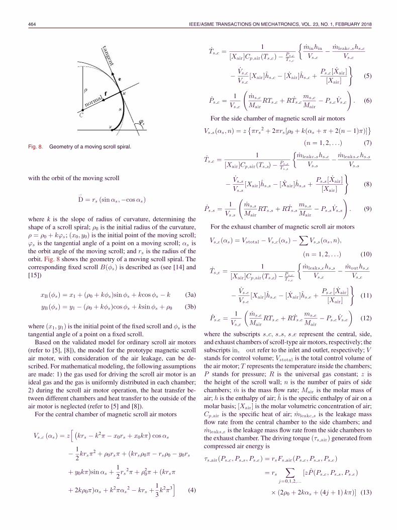
Fig. 8. Geometry of a moving scroll spiral.
with the orbit of the moving scroll
⇀
D = rs (sin αs,−cos αs)
where k is the slope of radius of curvature, determining theshape of a scroll spiral; ρ0 is the initial radius of the curvature,ρ = ρ0 + kϕs ; (x0, y0) is the initial point of the moving scroll;ϕs is the tangential angle of a point on a moving scroll; αs isthe orbit angle of the moving scroll; and rs is the radius of theorbit. Fig. 8 shows the geometry of a moving scroll spiral. Thecorresponding fixed scroll B(φs) is described as (see [14] and[15])
xB(φs) = x1 + (ρ0 + kφs)sin φs + kcos φs − k (3a)
yB(φs) = y1 − (ρ0 + kφs)cos φs + ksin φs + ρ0 (3b)
where (x1, y1) is the initial point of the fixed scroll and φs is thetangential angle of a point on a fixed scroll.
Based on the validated model for ordinary scroll air motors(refer to [5], [8]), the model for the prototype magnetic scrollair motor, with consideration of the air leakage, can be de-scribed. For mathematical modeling, the following assumptionsare made: 1) the gas used for driving the scroll air motor is anideal gas and the gas is uniformly distributed in each chamber;2) during the scroll air motor operation, the heat transfer be-tween different chambers and heat transfer to the outside of theair motor is neglected (refer to [5] and [8]).
For the central chamber of magnetic scroll air motors
Vs c (αs) = z[ (
krs − k2π − x0rs + x0kπ)cos αs
− 12krsπ
2 + ρ0rsπ + (krsρ0π − rsρ0 − y0rs
+ y0kπ)sinαs +12rs
2π + ρ20π + (krsπ
+ 2kρ0π)αs + k2παs2 − krs +
13k2π3
](4)
Ts c =1
[Xair ]Cp,air(Ts c) − Ps c
Ts c
{minhin
Vs c− mleakc shs c
Vs c
− Vs c
Vs c[Xair ]hs c − [Xair ]hs c +
Ps c [Xair ][Xair ]
}(5)
Ps c =1
Vs c
(ms c
MairRTs c + RTs c
ms c
Mair− Ps c Vs c
). (6)
For the side chamber of magnetic scroll air motors
Vs s(αs, n) = z{πrs
2 + 2πrs [ρ0 + k(αs + π + 2(n − 1)π)]}
(n = 1, 2, . . .) (7)
Ts c =1
[Xair ]Cp,air(Ts s) − Ps s
Ts s
{mleakc shs c
Vs s− mleaks ehs s
Vs s
− Vs s
Vs s[Xair ]hs s − [Xair ]hs s +
Ps s [Xair ][Xair ]
}(8)
Ps s =1
Vs s
(ms s
MairRTs s + RTs s
ms s
Mair− Ps sVs s
). (9)
For the exhaust chamber of magnetic scroll air motors
Vs e(αs) = Vstotal − Vs c(αs) −∑
Vs s(αs, n),
(n = 1, 2, . . .) (10)
Ts e =1
[Xair ]Cp,air(Ts e) − Ps e
Ts e
{mleaks ehs s
Vs e− mouths e
Vs e
− Vs e
Vs e[Xair ]hs e − [Xair ]hs e +
Ps e [Xair ][Xair ]
}(11)
Ps e =1
Vs e
(ms e
MairRTs e + RTs e
ms e
Mair− Ps eVs e
)(12)
where the subscripts s c, s s, s e represent the central, side,and exhaust chambers of scroll-type air motors, respectively; thesubscripts in, out refer to the inlet and outlet, respectively; Vstands for control volume; Vstotal is the total control volume ofthe air motor; T represents the temperature inside the chambers;P stands for pressure; R is the universal gas constant; z isthe height of the scroll wall; n is the number of pairs of sidechambers; m is the mass flow rate; Mair is the molar mass ofair; h is the enthalpy of air; h is the specific enthalpy of air on amolar basis; [Xair ] is the molar volumetric concentration of air;Cp,air is the specific heat of air; mleakc s is the leakage massflow rate from the central chamber to the side chambers; andmleaks e is the leakage mass flow rate from the side chambers tothe exhaust chamber. The driving torque (τs air) generated fromcompressed air energy is
τs air(Ps c , Ps s , Ps e) = rsFs air(Ps c , Ps s , Ps e)
= rs
∑j=0,1,2,...
[zP (Ps c , Ps s , Ps e)
× (2ρ0 + 2kαs + (4j + 1) kπ)] (13)

LUO et al.: NEW SCROLL-TYPE AIR MOTOR WITH MAGNETIC SPIRALS 465
where Fs air(Ps c , Ps s , Ps e) represents the driving force gener-ated from compressed air and P (Ps c , Ps s , Ps e) is the pressuredifference between the adjacent chambers (refer to [5] and [8]).The above is the modeling descriptions of the ordinary scroll airmotor, based on its “geometry and the fundamentals of thermo-dynamics and rotary motion.” Considering the magnetic torquegenerated from the induced magnetic field, the shaft acceleration(ωs) of a magnetic scroll air motor is given by
ωs =1Js
[−KS−C S (ωs, Ps c , Ps s , Ps e) − Kf sωs − Tl
+ τs air(Ps c , Ps s , Ps e) + τmagnet ] (14)
where Tl is the air motor load torque; the maximum of j is deter-mined by the number of the driving segments of scrolls; ωs andωs represent the rotor rotating angular speed and acceleration;Js is the air motor inertia; Kf s is the coefficient of kinematicviscous friction; KS−C S(ωs, Ps c , Ps s , Ps e) is the combina-tion effect on torque resulting from the static plus Coulombfrictions with the consideration of the effect from the magneticforce, which can be described as
KS−C S(ωs, Ps c , Ps s , Ps e)
=
{KS−C Fmag staticmax , ωs = 0
sign(ωs) × ∂s × KS−C Fmag staticmax , ωs �= 0(15)
where KS−C is a coefficient of this combination effect;∂s is the coefficient for the Coulomb friction, 0 < ∂s < 1;KS−C Fmag staticmax is the combined effect on torque from themagnetic force and the maximum mechanical static friction.
From the fundaments of magnetics, the magnetic torque gen-erated by the magnetic field can be defined as (see [24]–[26])
τmagnet = �rs�Fmagnet = rsFmagnet × cosθ = rscosθ
×[− d
dx(Wa + Wm )
]
= rscosθ ×[− d
dx
(∫
vola
(∫ B
0
⇀
Had⇀
Ba
)dva
+∫
volm
(∫ B
Br
⇀
Hm d⇀
Bm
)dvm
)](16)
where θ is the angle between the directions of the moving scrollmovement and the resultant magnetic force; Fmagnet is the re-sultant force on the magnet(s); x represents the object position;Wa is the energy in an air medium (e.g., a chamber) with the
magnetic flux density (⇀
Ba ) and the magnetic field strength (⇀
Ha );vola and dva are, respectively, the volume of the air field and thevolume of its segment; Wm is the energy in a magnet block with
the magnetic flux density (⇀
Bm ) and the magnetic field strength
Fig. 9. Comparison of measurement-based and simulated magnetictorques.
(⇀
Hm ); volm and dvm are, respectively, the volume of magnetblock and the volume of its segment.
B. Simulation Study
The simulation study is implemented via using the devel-oped model in ANSYS Maxwell with MathWorks MATLAB,the overall variation trend of the magnetic torque from the sim-ulated results is roughly comparable to the measurement-baseddata (τmagnet from (1) in Section IV). The comparison is shownin Fig. 9, from which it can be seen that there are some differ-ences between the simulated results and the measurement-baseddata. This difference is mainly caused by the assumption madefor mechanical static friction which is used in the calculationof τmagnet . It is assumed that the maximum mechanical staticfriction is evenly distributed. But, in practice, it varies with thedifferent orbit angles (αs). One case is shown in Fig. 7 (the redsolid line): the starting torque for the ordinary scroll air mo-tor without magnets is unevenly distributed which is due to thevaried maximum mechanical static friction with orbit angles.
For the magnetic scroll air motor, the resultant magneticforce/torque can affect the clearances between the moving andfixed scrolls, in turn the air leakage of the scroll air motor.There are two types of leakages associated with the air motoroperation, i.e., flank and radial leakages (refer to [5]). Basedon the current prototype design, the magnetic force/torque canonly vary the flank leakage during the operation. The mass flowrate of the flank leakage is [5] given by (17) as shown at thebottom of this page, where ar is leakage flow coefficient; γ isspecific heat ratio of air, γ ≈ 1.4; ρ is the compressed air den-sity; subscript i stands for the ith pair of side chambers; andδf is the flank gap clearance, which can be assumed to be aconstant, for ordinary scroll air motors δf ≈ 0.01 − 0.06 mm[5], [7], [11], [27], [28]. From (17), the quantity of air leakagechanges with the variation of clearance δf , which is affectedby the magnetic force/torque. Due to the difficulties in mea-suring the leakage and the magnetic force during the air motoroperation, the investigation of leakage effect with efficiencyanalysis is performed via simulation study. It is assumed that
mflank =
⎧⎪⎪⎪⎪⎨⎪⎪⎪⎪⎩
2arzδf ρi
√2γ
γ−1RTi
[(Pi + 1
Pi
)2/γ
−(
Pi + 1
Pi
)(γ+1)/γ]
(unchoked)
2arzδf ρi
√2γ
γ−1RTi
[(2
γ+1
)(2/γ−1)−(
2γ+1
)(γ+1)/(γ−1)]
(choked)
(17)
466 IEEE/ASME TRANSACTIONS ON MECHATRONICS, VOL. 23, NO. 1, FEBRUARY 2018
Fig. 10. Relationship between magnetic torque and flank leakageclearance.
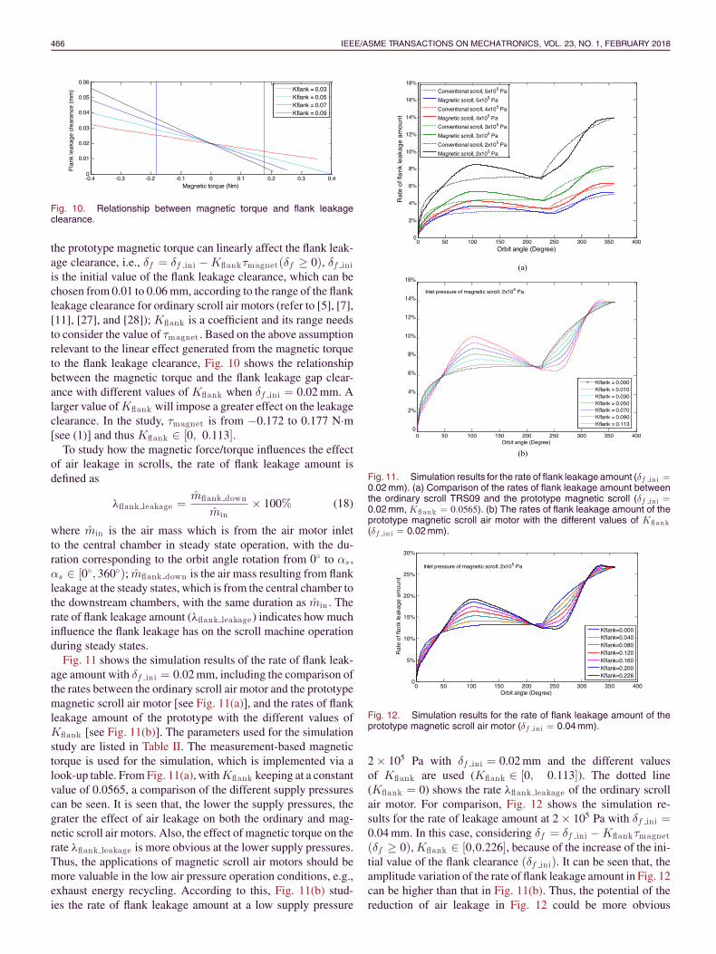
the prototype magnetic torque can linearly affect the flank leak-age clearance, i.e., δf = δf ini − Kflankτmagnet(δf ≥ 0), δf iniis the initial value of the flank leakage clearance, which can bechosen from 0.01 to 0.06 mm, according to the range of the flankleakage clearance for ordinary scroll air motors (refer to [5], [7],[11], [27], and [28]); Kflank is a coefficient and its range needsto consider the value of τmagnet . Based on the above assumptionrelevant to the linear effect generated from the magnetic torqueto the flank leakage clearance, Fig. 10 shows the relationshipbetween the magnetic torque and the flank leakage gap clear-ance with different values of Kflank when δf ini = 0.02 mm. Alarger value of Kflank will impose a greater effect on the leakageclearance. In the study, τmagnet is from −0.172 to 0.177 N·m[see (1)] and thus Kflank ∈ [0, 0.113].
To study how the magnetic force/torque influences the effectof air leakage in scrolls, the rate of flank leakage amount isdefined as
λflank leakage =mflank down
min× 100% (18)
where min is the air mass which is from the air motor inletto the central chamber in steady state operation, with the du-ration corresponding to the orbit angle rotation from 0◦ to αs ,αs ∈ [0◦, 360◦); mflank down is the air mass resulting from flankleakage at the steady states, which is from the central chamber tothe downstream chambers, with the same duration as min . Therate of flank leakage amount (λflank leakage) indicates how muchinfluence the flank leakage has on the scroll machine operationduring steady states.
Fig. 11 shows the simulation results of the rate of flank leak-age amount with δf ini = 0.02 mm, including the comparison ofthe rates between the ordinary scroll air motor and the prototypemagnetic scroll air motor [see Fig. 11(a)], and the rates of flankleakage amount of the prototype with the different values ofKflank [see Fig. 11(b)]. The parameters used for the simulationstudy are listed in Table II. The measurement-based magnetictorque is used for the simulation, which is implemented via alook-up table. From Fig. 11(a), with Kflank keeping at a constantvalue of 0.0565, a comparison of the different supply pressurescan be seen. It is seen that, the lower the supply pressures, thegrater the effect of air leakage on both the ordinary and mag-netic scroll air motors. Also, the effect of magnetic torque on therate λflank leakage is more obvious at the lower supply pressures.Thus, the applications of magnetic scroll air motors should bemore valuable in the low air pressure operation conditions, e.g.,exhaust energy recycling. According to this, Fig. 11(b) stud-ies the rate of flank leakage amount at a low supply pressure
Fig. 11. Simulation results for the rate of flank leakage amount (δf in i =0.02 mm). (a) Comparison of the rates of flank leakage amount betweenthe ordinary scroll TRS09 and the prototype magnetic scroll (δf in i =0.02 mm, Kflank = 0.0565). (b) The rates of flank leakage amount of theprototype magnetic scroll air motor with the different values of Kflank(δf in i = 0.02 mm).
Fig. 12. Simulation results for the rate of flank leakage amount of theprototype magnetic scroll air motor (δf in i = 0.04 mm).
2 × 10⁵ Pa with δf ini = 0.02 mm and the different valuesof Kflank are used (Kflank ∈ [0, 0.113]). The dotted line(Kflank = 0) shows the rate λflank leakage of the ordinary scrollair motor. For comparison, Fig. 12 shows the simulation re-sults for the rate of leakage amount at 2 × 10⁵ Pa with δf ini =0.04 mm. In this case, considering δf = δf ini − Kflankτmagnet(δf ≥ 0), Kflank ∈ [0,0.226], because of the increase of the ini-tial value of the flank clearance (δf ini). It can be seen that, theamplitude variation of the rate of flank leakage amount in Fig. 12can be higher than that in Fig. 11(b). Thus, the potential of thereduction of air leakage in Fig. 12 could be more obvious

LUO et al.: NEW SCROLL-TYPE AIR MOTOR WITH MAGNETIC SPIRALS 467
Fig. 13. Simulation results of flank leakage clearance versus energyefficiency.
compared to the results shown in Fig. 11(b). This indicates thatthe potential of the reduction of air leakage not only depends onthe strength of magnetic force/torque but also the initial originalair leakage with its clearance.
The available air power at the inlet can be defined as the maxi-mum potential power that can be extracted from the compressedair [29]
Pairin = min [(hin − hatm) − Tatm(sin − satm)] (19)
where subscripts in and atm are the inlet and atmospheric statesof the compressed air, respectively; s is the specific entropy ofair. From the fundamentals of thermodynamics, an alternativefor calculating the air power can be [29]–[31]
Pairin = minRairTatm
×[ln
Pin
Patm+
γ
γ − 1
(Tin
Tatm− 1 − ln
Tin
Tatm
)]
(20)
where Rair is the gas constant for air. The energy efficiency ofthe magnetic scroll air motor can be defined as
η =Pmag scroll
Pairin=
ωs
Pairin[τs air(Ps c , Ps s , Ps e) + τmagnet
− KS−C S (ωs, Ps c , Ps s , Ps e) − Kf sωs ] (21)
where Pmag scroll is the generated net power from the shaft ofthe magnetic scroll air motor. Fig. 13 shows the simulation re-sults of the change of energy efficiency of the magnetic scrollair motor with the flank leakage clearance variation. In the sim-ulation study, the clearance causing the radial leakage is set asa constant of 0.015 mm, and the radial leakage calculation issimilar to the flank leakage (for details, refer to [5] and [28]). InFig. 13, when the supply inlet pressure is at 2 × 10⁵ Pa, with theassumption that the original flank leakage clearance is 0.02 mm,the energy efficiency can be maximally improved by about 4.0%(considering the flank leakage clearance can be reduced to 0); thepotential of efficiency improvement can be up to around 8.3%,when the original value of the flank clearance δf ini = 0.04 mm;the energy efficiency has the possibility to improve around 15%if δf ini = 0.06 mm.
C. Further Discussion
The simulation study reported in this section shows the rela-tionship between the magnetic torque, the flank leakage, and theenergy efficiency of the magnetic scroll air motor. Figs. 11 and
12 indicate that the current magnetization strategy for the pro-totype magnetic scroll can reduce the air leakage only in somesections but not the whole cycle. This gives important informa-tion in developing a better strategy for the design of magneticscroll air motors. It can be considered that using electromagnetsto replace some of the permanent magnets to be inserted into thescroll air motor would allow the generated magnetic torque tobe controlled by the supplied excitation current into the wind-ings wrapped around the electromagnets. This will optimize thesections of air leakage reduction in each cycle operation. Theresearch to the new strategy is currently on-going work withinthe research group.
VI. CONCLUSION
An innovative scroll-type air motor with magnetized spiralsis proposed in the paper. The realization of the magnetic scrollconcept is explored and a feasible technique is proposed, thatis, machining two thin slots on both fixed and moving scrolls tohost the magnetized spiral segments. A prototype of the mag-netic scroll air motor is manufactured, which proves the feasi-bility. The technique proposed retains the original mechanicalstructure for airflow and also protects the embedded magneticmaterials.
The simulation study on two different topologies of embed-ding magnetic spiral segments inside the air motor enhances theunderstanding of the corresponding magnetic fields and the fluxdensity distributions. This can provide a guide for optimizingmagnetization of the scrolls. The effect of the magnetizationand the generated magnetic torque on the scroll air motor per-formance and operation is studied via modeling, simulation, andexperiment.
From the study, it can be concluded that: the magnetizedspirals will result in additional torques and their directions de-pend on the direction of magnetization; the developed magneticscroll air motor has potential in reducing the leakage betweenair chambers and, in turn, improving the energy efficiency. Thestudy shows that it has potential to improve efficiency by around15% at 2 × 10⁵ Pa supply pressure condition with the initialflank clearance at 0.06 mm. This opens a wider opportunityfor scroll technology to be used in the applications with low airpressure operation conditions, such as exhaust energy recycling.
ACKNOWLEDGMENT
The authors would like to thank the Engineering and PhysicalSciences Research Council (EPSRC) for the funding supportand the China 973 Research Programme to enable the U.K.–China technical discussion. The authors would also like to thankDr. H. Sun for his support while he was the Facility Manager ofthe research group.
REFERENCES
[1] R. W. Shaffer, “Chapter 12: Scroll compressors,” in Compressor Hand-book, Paul C. Hanlon, Ed. New York, NY, USA: McGraw-Hill, 2001.
[2] Y. Chen, N. P. Halm, E. A. Groll, and J. E. Braun, “Mathematical modelingof scroll compressors—Part I: Compression process modeling,” Int. J.Refrig., vol. 25, no. 6, pp. 731–750, Sep. 2002.
468 IEEE/ASME TRANSACTIONS ON MECHATRONICS, VOL. 23, NO. 1, FEBRUARY 2018
[3] Compressed air batteries, Flow battery Ltd., 2012. [Online]. Available:http://www.flowbattery.co.uk/compressed-air-batteries. Accessed on: Jan.16, 2016.
[4] X. Luo, H. Sun, and J. Wang, “An energy efficient pneumatic-electricalsystem and control strategy development,” in Proc. Amer. Control Conf.,2011, pp. 4743–4748.
[5] J. Wang et al., “Mathematical modeling study of scroll air motors andenergy efficiency analysis—Part II,” IEEE/ASME Trans. Mechatronics,vol. 16, no. 1, pp. 122–132, Feb. 2011.
[6] T. Yanagisawa, Y. Fukuta, T. Ogi, and T. Hikichi, “Performance of an oil-free scroll-type air expander,” in Proc. ImechE Conf. Trans CompressorsTheir Syst., 2001, pp. 167–174.
[7] P. Song, M. Wei, L. Shi, S. N. Danish, and C. Ma, “A review of scrollexpanders for organic Rankine cycle systems,” Appl. Therm. Eng., vol. 75,pp. 54–64, Jan. 2015.
[8] J. Wang, L. Yang, X. Luo, S. Mangan, and J. W. Derby, “Mathemati-cal modeling study of scroll air motors and energy efficiency analysis—Part I,” IEEE/ASME Trans. Mechatronics, vol. 16, no. 1, pp. 112–121,Feb. 2011.
[9] R. Dickes, “Design and fabrication of a variable wall thickness two-stagescroll expander to be integrated in a micro-solar power plant,” M.S. thesis,Dept. Aero. Mech. Eng., Univ. Liege, Liege, Belgium, 2013.
[10] M. Wei, P. Song, B. Zhao, L. Shi, Z. Wang, and C. Ma, “Unsteady flow inthe suction process of a scroll expander for an ORC waste heat recoverysystem,” Appl. Therm. Eng., vol. 78, pp. 460–470, Mar. 2015.
[11] X. Gao, L. S. Li, Y. Zhao, P. C. Shu, and J. Shen, “Research on a scrollexpander used for recovering work in a fuel cell,” Int. J. Thermodyn.,vol. 7, no. 1, pp. 1–8, Mar. 2004.
[12] X. Luo, J. Wang, H. Sun, J. W. Derby, and S. J. Mangan, “Study of a newstrategy for pneumatic actuator system energy efficiency improvementvia the scroll expander technology,” IEEE/ASME Trans. Mechatronics,vol. 18, no. 5, pp. 1508–1518, Oct. 2013.
[13] X. Luo, J. Wang, C. Krupke, and H. Xu, “Feasibility study of a scroll ex-pander for recycling low-pressure exhaust gas energy from a vehicle gaso-line engine system,” Energies, vol. 9, no. 4, 2016, doi: 10.3390/en9040231.
[14] C. Krupke, J. Wang, J. Clarke, and X. Luo, “Modeling and experimentalstudy of a wind turbine system in hybrid connection with compressed airenergy storage,” IEEE Trans. Energy Convers., vol. 32, no. 1, pp. 137–145,Mar. 2017.
[15] L. Varriale, Compressed air battery, 2012. [Online]. Available:https://www.bestmag.co.uk/tags/compressed-air-battery. Accessed on:Jul. 20, 2016.
[16] Affordable domestic microCHP boiler, 2014. [Online]. Available:http://flowgroup.uk.com/. Accessed on: Nov. 20, 2016.
[17] Airsquared scroll expander products and projects, 2011. [Online].Available: https://airsquared.com/products/scroll-expanders/. Accessedon: Jun. 12, 2017.
[18] “Rear-earth permanent magnets VACODYM and VACOMAX,” Productbrochure, VACUUMSCHMELZE GmbH & Co. KG, 2014. [Online].Available: http://www.vacuumschmelze.com/en/products/permanent-magnets-assemblies.html. Accessed on: May 26, 2016.
[19] X. Luo, H. Sun, and J. Wang, “A novel magnetic scroll expander as a drivefor electricity generation,” in Proc. 7th IET Int. Conf. Power Electron.Mach. Drives, 2014, pp. 1–6.
[20] J. Wang, J. Pu, J. P. Moore, and Z. Zhang, “Modelling study and servo-control of air motor systems,” Int. J. Control, vol. 71, no. 3, pp. 459–476,1998.
[21] Y. Katano, K. Nakano, M. Otsuki, and H. Matsukawa, “Novel fric-tion law for the static friction force based on local precursor slip-ping,” Scientific Reports, vol. 4, no. 6324, 2014. [Online]. Available:http://www.nature.com/articles/srep06324. Accessed on: Apr. 16, 2016.
[22] B. Armstrong-Helouvry, P. Dupont, and C. C. Dewit, “A surrey of modelsanalysis tools and compensation methods for the control of machines withfriction,” Automatica, vol. 30, pp. 1083–1138, 1994.
[23] J. Gravesen and C. Henriksen, “The geometry of the scroll compressor,”SIAM Rev., vol. 43, pp. 113–126, 2001.
[24] W. H. Hayt, Jr., and J. A. Buck, Engineering Electromagnetics, 7th ed.New York, NY, USA: McGraw-Hill, 2006, pp. 290–305.
[25] P. A. Watterson, “Energy calculation of a permanent magnet system bysurface and flux integrals (the flux-mmf method),” IEEE Trans. Magn.,vol. 36, no. 2, pp. 470–475, Aug. 2000.
[26] H. C. Lovatt and P. A. Watterson, “Energy stored in permanent magnets,”IEEE Trans. Magn., vol. 35, no. 1, pp. 505–507, Jan. 1999.
[27] X. Q. Li and J. Wang, “Influence of axial clearance of orbiting scrollon working performance of scroll compressor,” J. Compressor Technol.,vol. 1, pp. 23–26, 2007.
[28] Z. L. Gu, Y. Z. Yu, and S. Y. Feng, Eds. Scroll Compressors and ScrollMechanics. Xi’an, China: Shaanxi Sci. Technol. Press, 1998.
[29] T. D. Eastop and A. McConkey, Applied Thermodynamics for EngineeringTechnologists. Singapore: Longman, 1993, pp. 20–56, 115–121.
[30] M. Cai, K. Kawashima, and T. Kagawa, “Power assessment of flowingcompressed air,” Trans. ASME J. Fluids Eng., vol. 128, pp. 402–405,2006
[31] M. Cai, T. Kaawa, and K. Kawashima, “Energy conversion mechanics andpower evaluation of compressible fluid in pneumatic actuator systems,”presented at the 37th Intersoc. Energy Convers. Eng. Conf., Washington,DC, USA, 2002.
Xing Luo received the M.Sc. degree in mi-croelectronic systems and telecommunicationsfrom the University of Liverpool, Liverpool, U.K.,in 2006, and the Ph.D. degree in mechatronicsfrom the University of Birmingham, Birmingham,U.K., in 2010.
He is currently a Senior Research Fellowof energy conversion and control engineeringwith the School of Engineering, University ofWarwick, Coventry, U.K. His current researchinterests include system modeling and control
on electrical energy storage, power systems, vehicle and pneumaticsystems, hardware-in-the-loop simulation, energy-efficient systems, andreal-time control development.
Jihong Wang (M’06–SM’08) received the B.E.degree from the Wuhan University of Technol-ogy, Wuhan, China, in 1982, the M.Sc. degreefrom the Shandong University of Science andTechnology, Shandong, China, in 1985, and thePh.D. degree from Coventry University, Coven-try, U.K., in 1995.
She is currently a Professor of power systemsand control engineering with the School of En-gineering, University of Warwick, Coventry. Hercurrent research interests include nonlinear sys-
tem control, system modeling and identification, power systems, energy-efficient actuators and systems, and applications of intelligent algorithms.
Dr. Wang was a Technical Editor for the IEEE TRANSACTIONS ONMECHATRONICS.
Leonid Shpanin (M’08) received the Ph.D. de-gree in electrical and electronic engineering fromthe University of Liverpool, Liverpool, U.K., in2006.
He is currently a Lecturer in aerospace withthe Faculty of Engineering, Environment, andComputing, Coventry University, Coventry, U.K.He has over ten years of industrial experience inelectrical/electronic engineering and radio fre-quency communication systems where he wasinvolved in the variety of research, engineering,
and management positions in the U.K. and across the world. His currentresearch interests include pulsed power systems, high voltage dc circuitbreakers, renewable energy systems, unmanned aerial vehicle energymanagement systems, and power systems modeling and control.
Mark Dooner received the M.Eng. degree inelectronic engineering and the Ph.D. degreein automotive mechatronics from the Universityof Warwick, Coventry, U.K., in 2011 and 2017,respectively.
He is a Research Fellow with the Power andControl Systems Research Laboratory, Univer-sity of Warwick. His current research interestsinclude energy storage systems modeling andcontrol, electromagnetic modeling, and powersystems.