Embed Size (px)
Citation preview
Fe
at
ur
e
Ar
ti
cl
e
40 English Edition No.10 November 2006
Feature Article
A New Sanitary Conductivity Meter and the Future Management of Pharmaceutical Water
Kiichiro Tomioka
We have developed a conductivity meter and sanitary electrodes (two types) for pharmaceutical water that meet the conductivity requirements of the United States Pharmacopeia (USP) General Chapters article 645. In particular, the fl ow-through type does not have any inner projections inside, which allows a full bore structure and excellent cleanability. Ideal sanitary properties corresponding to strict sanitary conditions for food, etc. are required by customers. We have concurrently developed a validation kit for performance evaluation to support the customer GMP (Good Manufacturing Practice) system. In pharmaceutical processes, analyzers are not used for process control as often as in petrochemical processes. However, the use of analyzers is actively being considered under the leadership of the Food and Drug Administration (FDA). The trend in US Pharmacopeia is toward more reliable and safer water, and the importance of water management is increasing.
Introduction
Accord i ng to t he Japa nese Pha r macopeia (J P) ,
pharmaceutical water is broadly classified into water,
purified water (PW), sterile purified water (SPW), and
water for injection (WFI). Various testing requirements
are specifi ed for each. For the United States Pharmacopeia
(USP), pharmaceutical water is further classified into
detailed categories based on usage.
In the 23rd amendment of the United States Pharmacopeia
(USP23), 2003, the conventional off-line purity test was
changed to an on-line first stage test using a conductivity
meter. PW and WFI are required to pass this first stage
test. If not, execution of the next stage test is made
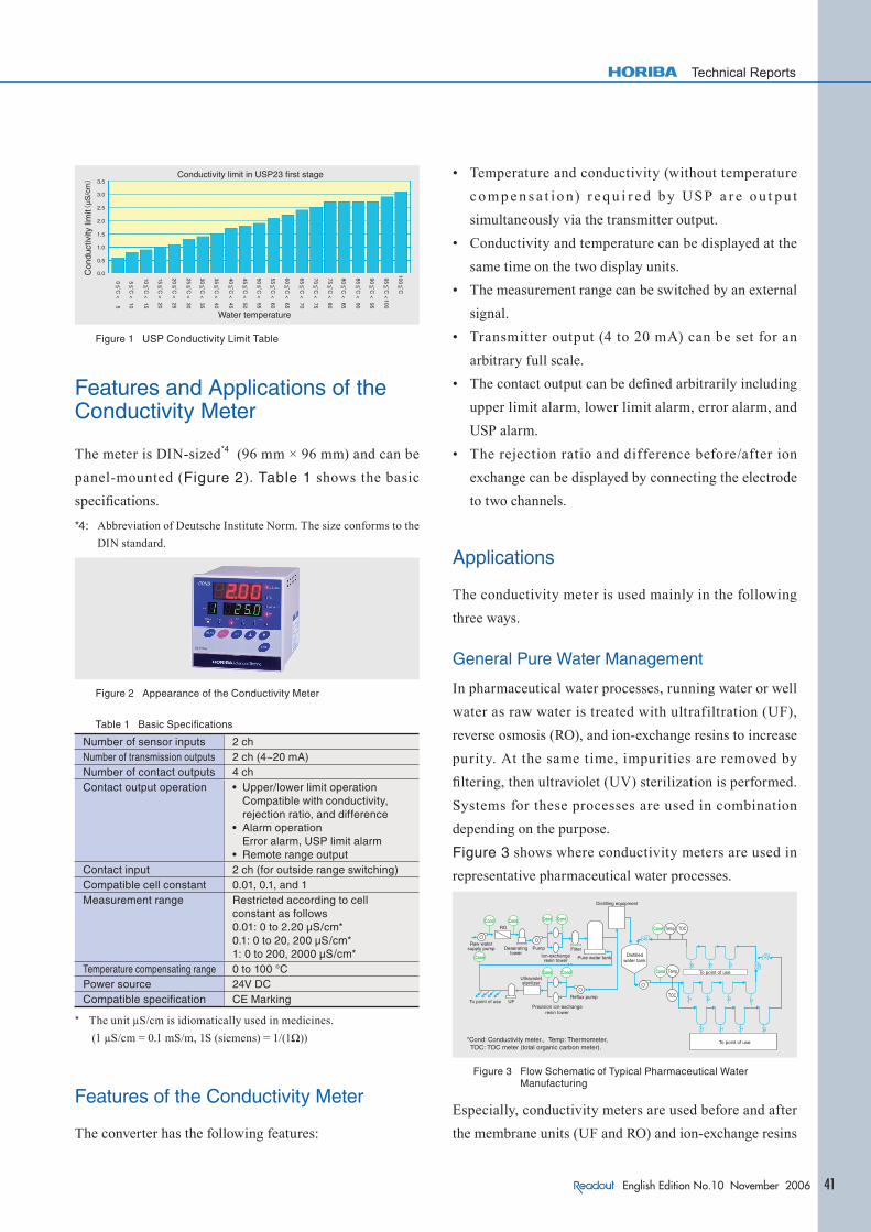
compulsory. The relationship between water temperature
and conductivity is described in Figure 1 and the first
stage test is carried out in order to verify that conductivity
is below this limit. Note that the off-line purity test is
car r ied out in JP (14th amendment). Based on this
background, conductivity meters have been adopted for
WFI management criteria and so conductivity meters are
widely used. Also in Japan, WFI is frequently managed
according to USP directives, and conductivity meters are
the on-l ine inst r uments most f requent ly used in
pharmaceutical water facilities. In this article, a newly
constructed validation system*1 has also been introduced.
The system is compatible with the sanitary electrode*2
specially developed for conductivity monitoring, the
meter, and GMP*3. Furthermore, the future direction of
pharmaceutical water management is summarized.
*1: Evaluation system to verify whether the instrument satisf ies
requirements and document the verifi cation.
*2: An electrode compliant with strict sanitary conditions for food,
etc.
*3: Good Manufacturing Practice: Criteria specified by FDA (Food
and Drug Administration) or Ministry of Health, Labor and
Wel f a r e i n o r d e r t o s e c u r e q u a l i t y i n ph a r m a c e u t i c a l
manufacturing and perform manufacturing and quality control
adequately.
Technical Reports
41English Edition No.10 November 2006
Water temperature
Conductivity limit in USP23 first stage
Con
duct
ivity
lim
it
Figure 1 USP Conductivity Limit Table
Features and Applications of the Conductivity Meter
The meter is DIN-sized*4 (96 mm × 96 mm) and can be
panel-mounted (Figure 2). Table 1 shows the basic
specifi cations.
*4: Abbreviation of Deutsche Institute Norm. The size conforms to the
DIN standard.
Figure 2 Appearance of the Conductivity Meter
Table 1 Basic Specifi cations
Number of sensor inputs 2 chNumber of transmission outputs 2 ch (4~20 mA)Number of contact outputs 4 chContact output operation • Upper/lower limit operation
Compatible with conductivity, rejection ratio, and difference
• Alarm operationError alarm, USP limit alarm
• Remote range outputContact input 2 ch (for outside range switching)Compatible cell constant 0.01, 0.1, and 1Measurement range Restricted according to cell
constant as follows 0.01: 0 to 2.20 µS/cm*0.1: 0 to 20, 200 µS/cm*1: 0 to 200, 2000 µS/cm*
Temperature compensating range 0 to 100 °CPower source 24V DCCompatible specifi cation CE Marking
* The unit μS/cm is idiomatically used in medicines.
(1 μS/cm = 0.1 mS/m, 1S (siemens) = 1/(1Ω))
Features of the Conductivity Meter
The converter has the following features:
• Temperature and conductivity (without temperature
c o m p e n s a t i o n) r e q u i r e d by USP a r e o u t p u t
simultaneously via the transmitter output.
• Conductivity and temperature can be displayed at the
same time on the two display units.
• The measurement range can be switched by an external
signal.
• Transmitter output (4 to 20 mA) can be set for an
arbitrary full scale.
• The contact output can be defi ned arbitrarily including
upper limit alarm, lower limit alarm, error alarm, and
USP alarm.
• The rejection ratio and difference before/after ion
exchange can be displayed by connecting the electrode
to two channels.
Applications
The conductivity meter is used mainly in the following
three ways.
General Pure Water Management
In pharmaceutical water processes, running water or well
water as raw water is treated with ultrafiltration (UF),
reverse osmosis (RO), and ion-exchange resins to increase
purity. At the same time, impurities are removed by
fi ltering, then ultraviolet (UV) sterilization is performed.
Systems for these processes are used in combination
depending on the purpose.
Figure 3 shows where conductivity meters are used in
representative pharmaceutical water processes.
Raw watersupply pump Deaerating
towerPump
Ion-exchangeresin tower
Filter
Pure water tank
Distilling equipment
Distilledwater tank
To point of use
To point of use
To point of use
Ultravioletsterilizer
Reflux pump
Precision ion-exchangeresin tower
*Cond: Conductivity meter., Temp: Thermometer, TOC: TOC meter (total organic carbon meter).
Figure 3 Flow Schematic of Typical Pharmaceutical Water Manufacturing
Especially, conductivity meters are used before and after
the membrane units (UF and RO) and ion-exchange resins

Fe
at
ur
e
Ar
ti
cl
e
42 English Edition No.10 November 2006
Feature Article A New Sanitary Conductivity Meter and the Future Management of Pharmaceutical Water
to check equipment function. Taking advantage of the
2-channel specifi cation, this conductivity meter is used to
monitor prior and subsequent conductivities and so
manage the equipment by calculating the rejection ratio
from the conductivity. The measurement range of this
meter extends from raw water to pure water levels.
Management of Sterile Purifi ed Water (SPW)
As shown in Figure 3, water purifi ed by the primary side
water purifying equipment is sterilized (made pyrogen-
free *5) by the distilling equipment and then used to
manufacture water for injection (WFI). This line is
required to be extremely clean.
Here, water is kept between 80 and 85 °C, supplied to the
point of use, and circulated. To use it as WFI, the
USP<645> conductivity meter is required to satisfy the
following criteria.
(1) Conductivity of water shall be below the prescribed
value (limit value) for each temperature (Figure 1).
(2) Temperature shall not be compensated for conductivity
being measured.
(3) The conductivity meter shall be able to continuously
output conductivity and temperature at the same time.
(4) The display resolution of the conductivity meter shall
be 0.1 μS/cm.
The limit value is input to the conductivity meter to
manage (1) above. If conductivity exceeds the limit value,
an alarm is activated. In addition, there is a function to set
up the management level arbitrarily between 0 and 100%
against the standard value, i.e., the self-management level
can be specifi ed against the limit value. This conductivity
meter has a USP-compatible function to set up functions (1)
to (3) all together, which allows customers to easily set up
measurements in conformance with USP.
*5: Removal of substances such as cell walls of bacteria which can
cause fever (Pyrogen).
Cleaning Validation
The water manufacturing equipment must be periodically
cleaned. Often, the membrane parts have to be chemically
cleaned. For this purpose, the conductivity meter is used
as a rinse monitor and the cleaning process is managed by
monitor ing the conduct ivity af ter cleaning. This
conductivity meter, in particular, has a function for
expanding the range by using the external contact input.
When conductivity has dropped in the course of cleaning,
the meter is switched to the low range to verify the
direction, which makes it possible to more reliably verify
the cleaning effectiveness.
Features of Sensors used for Sanitary Conductivity Meter
The sensors consist of two types, a f low-through type
(Figure 4) and insertion type (Figure 5).
Figure 4 Flow-through Type
Figure 5 Insertion Type
Flow-through Type
The inside of this sensor does not have any projections,
and the inner diameter of the sensor is exactly the same as
the diameter of the connector piping, i.e a full bore
structure.
The sensors are available in a large assortment of sizes to
fi t fi ve types of piping diameters: 15 A*6, 1S, 1.5S, 2S, and
2.5S*7.
*6: Piping with the outside diameter of 21.7 mm based on JIS G 3459.
*7: Piping based on 3A standard (US sanitary standard). The number
before S indicates the outside diameter in inches.
Technical Reports
43English Edition No.10 November 2006
Because there are no projections, the f low-through type
sensors have the following advantages:
(1) The sensor section has no detention area.
(2) The sensor section can be treated in the same manner
as piping components.
(3) Sensor holders are unnecessary.
(4) Fluid substitution is executed immediately after
cleaning.
(5) Fluid removal from the sensor section can be executed
in the same way as with the piping.
(6) Because there are no projections or crevasses, an
excellent cleaning performance is evident compared to
conventional construction.
These advantages realize ideal sanitary properties.
Furthermore, electrolytic polishing (EP) is applied to the
electrode surface after #400 *8 polishing in order to
improve cleanability and chemical resistance. As adopted
in the insertion type structure discussed next, the seal
section has no crevasses.
Highly heat-resistant PTFE (Polytetrafl uoroethylene) and
PEEKTM plastics are used as the insulator materials and
f luorocarbon r ubbers (FK M) with h igh ant igas-
permeability are used as sealing materials. A double
sealing structure has been adopted.
*8: #400 is a type of fine powder for precision polishing of which the
average particle diameter is 30 μm (particle size of polishing agent
for grindstones JIS R 6001).
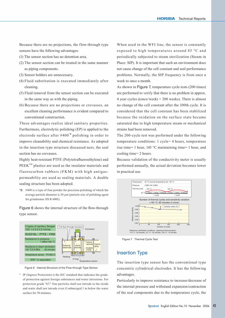
Figure 6 shows the internal structure of the fl ow-through
type sensor.
5 types of sanitary flanges15A 1.0 2.0 2.5 inches
Resistance to pressure 1 MPa/100 °C
Resistance to steam sterilization140 °C/0.6 MPa 60 minutes
Temperature sensor Pt1000 Ω
IP67* or equivalent
Full flow-through structureConnector
Externalelectrode
Externalelectrode
Internalelectrode Insulator
Externalpiping
PackingO-ring
Temperature sensor
Figure 6 Internal Structure of the Flow-through Type Sensor
* IP (Ingress Protection) is the IEC standard that indicates the grade.
of protection against foreign substances and water intrusions. For
protection grade "67," fine particles shall not intrude to the inside
and water shall not intrude even if submerged 1 m below the water
surface for 30 minutes.
When used in the WFI line, the sensor is constantly
exposed to h igh temperat u res a round 85 °C and
periodically subjected to steam sterilization (Steam in
Place: SIP). It is important that such an environment does
not cause change of the cell constant and seal performance
problems. Normally, the SIP frequency is from once a
week to once a month.
As shown in Figure 7, temperature cycle tests (200 times)
are performed to verify that there is no problem in approx.
4 year cycles ((once/week) × 200 weeks). There is almost
no change of the cell constant after the 100th cycle. It is
considered that the cell constant has been stabilized
because the oxidation on the surface state became
saturated due to high temperature steam or mechanical
strains had been removed.
The 200-cycle test was performed under the following
temperature conditions: 1 cycle= 4 hours, temperature
rise time= 1 hour, 145 °C maintaining time= 1 hour, and
cooling time= 2 hours.
Because validation of the conductivity meter is usually
performed annually, the actual deviation becomes lower
in practical use.
Reference: sterilization conditions <Japanese Pharmacopeia>115 °C - 30 minutes, 121 °C - 20 minutes, 126 °C - 10 minutes
Temperature: 22 °C (normal temperature) 145 °C
Pressure: 0 MPa 5 MPa
Thermal cycle: 145 °C 145 °C
1 hour 1 hour 2 hours 1 hour 1 hour 2 hours1 cycle 1 cycle
Number of thermal cycles and sensitivity variation<140 °C, 60 minutes or more>
Variation within 2%
Rel
ativ
e se
nsiti
vity
Number of cycles
Figure 7 Thermal Cycle Test
Insertion Type
The insertion type sensor has the conventional type
concentric cylindrical electrodes. It has the following
advantages.
Particularly to improve resistance to increase/decrease of
the internal pressure and withstand expansion/contraction
of the seal components due to the temperature cycle, the

Fe
at
ur
e
Ar
ti
cl
e
44 English Edition No.10 November 2006
Feature Article A New Sanitary Conductivity Meter and the Future Management of Pharmaceutical Water
spring structure and press-fit structure*9 are adopted for
the inside. The seal section is structured so that the joint
section adheres to each other and no crack develops
between the electrode section (metal) and insulator
(plastics) even if pressure f luctuation or temperature
fl uctuation occurs. In the pharmaceutical fi eld, especially,
cracks or fissures formed at a joint section can grow
microorganisms and present a problem with cleanabilty.
Thus, structural considerations are required.
*9: This is one of the component connection method@s. The joint
section is structured so as not to create crevasses by pressing a plastics component into a metal one (press-fi tting). To join without any crevasss, welding is used for joining metals together. However, welding cannot be used to join metals with plastics. Also, adhesive agents cannot be used in the pharmaceutical fi eld, because they deteriorate due to high temperatures and cause the eluton.
Basic Performance (Linearity)
As shown in Figure 8, an excellent linearity has been
verifi ed.
1 inch
1.5 inches
2 inches
Evaluation of linearity of the sanitary electrode
Con
duct
ivity
of s
anita
ry e
lect
rode
(μS
/cm
)
Standard conductivity (μS/cm)
Figure 8 Linearity (Flow-through Type)
Validation Conductivity Calibration
General testing methods for conductivity are prescribed
in JIS or the Japanese Pharmacopeia. Basically, the cell
constant*10 is examined using a potassium chloride
solution with the prescribed concentration (Table 2). The
cell constant of the conductivity cell is calibrated based
on a traceability system. As repeatability precision, ±2%
is guaranteed.
*10: The cell constant is examined by measuring the degree of
electrical conductivity of a standard solution using a conductivity meter and dividing the conductivity value in Table 2 by the measurement value (Electrical conductivity = Cell constant x Degree of electric conduction).
Table 2 JIS K 0101: Standard Conductivity Values indicated in the 1998 Industrial Water Testing Method
(Only values under 25˚C were extracted.)
KCI concentration Electric conductivity under 25 ˚CA 74.246 g/L 111340 µS/cmB 7.437 g/L 12860 µS/cmC 0.744 g/L 1409 µS/cmD 1/10 of C 147 µS/cm
Temperature Calibration
Platinum resistance elements (Pt1000Ω) are used in the
temperature sensor. In particular, resistance of the cable
which can cause errors is compensated for by the cable
compensating function and the element variations are
compensated for by inputting the resistance deviation of
the resistor under 0ºC.
Because conductivity is an extremely important parameter
for pharmaceutical water, validation of its calibration is
important. In relation to GMP, customers always perform
validation in the field annually. Transportable calibration
units (validation kits) are available so that prompt and
reliable calibration can be performed. Not only a standard
conductivity meter, standard sensor and distribution
holder that has been examined by the intra-company
traceability system but also components for connecting
with the customer's processes are compactly stored in this
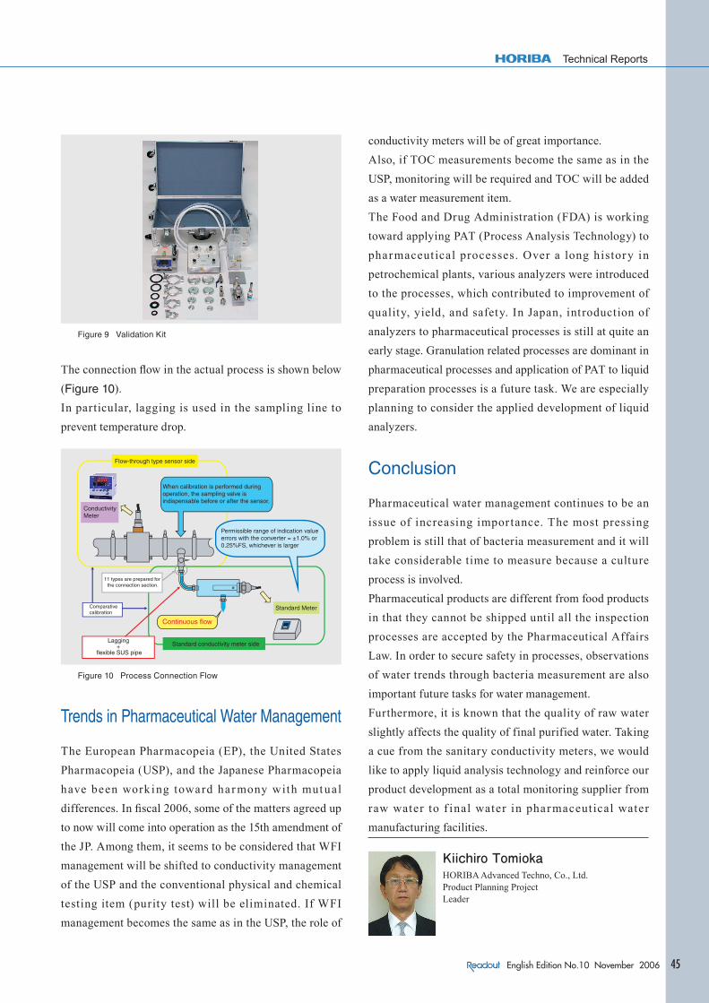
kit (Figure 9).
Sample water collected from the sampling valve located
near the sensor is supplied to the distribution holder.
Then, validation is performed by comparing temperature
and conductivity of the standard sensor and installed
sensor. This kit was developed in order to provide prompt
services for customers. By using this kit, validation can
be performed by not only the customers themselves but
also plant maintenance companies or calibration specialty
companies.
Technical Reports
45English Edition No.10 November 2006
Figure 9 Validation Kit
The connection fl ow in the actual process is shown below
(Figure 10).
In particular, lagging is used in the sampling line to
prevent temperature drop.
Flow-through type sensor side
Standard conductivity meter side
Standard Meter
Continuous flow
ConductivityMeter
When calibration is performed during operation, the sampling valve is indispensable before or after the sensor.
Permissible range of indication value errors with the converter = ±1.0% or 0.25%FS, whichever is larger
11 types are prepared for the connection section.
Comparative calibration
Lagging +
flexible SUS pipe
Figure 10 Process Connection Flow
Trends in Pharmaceutical Water Management
The European Pharmacopeia (EP), the United States
Pharmacopeia (USP), and the Japanese Pharmacopeia
have been work ing toward har mony with mutual
differences. In fi scal 2006, some of the matters agreed up
to now will come into operation as the 15th amendment of
the JP. Among them, it seems to be considered that WFI
management will be shifted to conductivity management
of the USP and the conventional physical and chemical
testing item (purity test) will be eliminated. If WFI
management becomes the same as in the USP, the role of
conductivity meters will be of great importance.
Also, if TOC measurements become the same as in the
USP, monitoring will be required and TOC will be added
as a water measurement item.
The Food and Drug Administration (FDA) is working
toward applying PAT (Process Analysis Technology) to
pharmaceut ical processes. Over a long history in
petrochemical plants, various analyzers were introduced
to the processes, which contributed to improvement of
quality, yield, and safety. In Japan, introduction of
analyzers to pharmaceutical processes is still at quite an
early stage. Granulation related processes are dominant in
pharmaceutical processes and application of PAT to liquid
preparation processes is a future task. We are especially
planning to consider the applied development of liquid
analyzers.
Conclusion
Pharmaceutical water management continues to be an
issue of increasing impor tance. The most pressing
problem is still that of bacteria measurement and it will
take considerable time to measure because a culture
process is involved.
Pharmaceutical products are different from food products
in that they cannot be shipped until all the inspection
processes are accepted by the Pharmaceutical Affairs
Law. In order to secure safety in processes, observations
of water trends through bacteria measurement are also
important future tasks for water management.
Furthermore, it is known that the quality of raw water
slightly affects the quality of final purified water. Taking
a cue from the sanitary conductivity meters, we would
like to apply liquid analysis technology and reinforce our
product development as a total monitoring supplier from
raw water to f inal water in pharmaceut ical water
manufacturing facilities.
Kiichiro TomiokaHORIBA Advanced Techno, Co., Ltd.Product Planning ProjectLeader