Embed Size (px)
Citation preview

* Dedicated to Professor Emeritus Drago Grdenić, Fellow of the Croatian Academy of Sciences and Arts, on the occasion of his
90th birthday. ** Author to whom correspondence should be addressed. (E-mail: [email protected])
CROATICA CHEMICA ACTA CCACAA, ISSN-0011-1643, ISSN-1334-417X
Croat. Chem. Acta 82 (2) (2009) 449–454 CCA-3334
Original Scientific Paper
A New Portable XRD/XRF Instrument for Non-destructive Analysis*
Augusto Pifferi,a,** Gaetano Campi,b Carmelo Giacovazzo,b and Ettore Gobbic
aIstituto di Cristallografia, CNR, sezione di Monterotondo, Area della Ricerca di Roma - Montelibretti, P. O. Box 10, 00016 Monterotondo St.(RM), Italy
bIstituto di Cristallografia, CNR, via G. Amendola 122, 70126 Bari, Italy cAssing S. P. A. via E. Amaldi 14, 00016 Monterotondo (Roma), Italy
RECEIVED MAY 15, 2008; REVISED AUGUST 4, 2008; ACCEPTED AUGUST 7, 2008
Abstract. A new integrated portable apparatus capable of in situ X-ray diffraction (XRD) and X-ray fluo-rescence (XRF) measurements is presented. The instrument equipment is based on a Theta-Theta horizon-tal goniometer projected and developed in order to optimize stability and reliability for apparatus of such a reduced size and capable of capturing both XRF and XRD information. The simultaneous XRD/XRF data collection is achieved by using a Si solid state detector counting the X-ray photons scattered from the sample as a function of both the energy and the angular step. The instrument is also equipped with a soft-ware developed in order to provide both ease of operation in the data collection and a complete and fast characterization of the materials in the data analysis.
Keywords: diffractometers, X-ray fluorescence, X-ray diffraction, data acquisition, data analysis
INTRODUCTION
Nowadays, there is a large number of fields where in situ non-destructive qualitative and quantitative analysis are required: e.g., archaeometry and materials of artistic interest,1–4 environment,5 and, in general, material sci-ence. The use of X-ray fluorescence analysis, being a non destructive multi-elemental method, gives the elemental composition.6,7 However, very often, e.g. in mineralogi-cal analysis, not only the element information but also the crystal structure information are necessary. The X-ray diffraction is a very powerful tool for identifying crystal structures. Using full-pattern fitting methods such as Rietveld techniques,8 it is now routinely pos-sible both the recognition of the chemical elements and the identification of the chemical phases to determine the abundance of all the phases present in a complex mixture. Moreover, when amorphous material is present in a sample, Rietveld refinement can be used to deter-mine the relative amount of amorphous material, and consequently the crystallinity of the sample. In conclu-sion, the combination of XRF and XRD techniques constitutes a powerful tool for a complete characteri-zation of the materials in several fields of investigation.
Thanks to the advent of non-cryogenic detectors and of small X-ray sources, several portable Energy-Dispersive X-ray Fluorescence spectrometers have been assembled.4,9–13 However, portable, efficient and com-pact instrumentation capable also of XRD measure-ments for field studies is not yet available, although:
a) a first prototype XRD/XRF instrument using a charge-coupled device (CCD) as detector, suitable mainly for planetary applications is under develop-ment;14
b) quite recently Uda et al.15 described a new port-able X-ray diffractometer equipped with an X-ray fluo-rescence spectrometer. The instrument is very compact: e.g., the goniometer is placed at a distance of 4 cm ± 1 cm from the sample. However, such geometrical design and the size of the apparatus do not allow to obtain XRD patterns with peaks sufficiently sharp (often larger than one degree). Very intriguing appears in the Uda work15 the idea to collect XRD/XRF patterns simul-taneously, by using white not monochromatised W radiation in energy dispersive mode, but also in this case the Si pin detector resolution capabilities worse the peak broadening;

450 A. Pifferi et al., A New Integrated Portable XRD/XRF Instrument
Croat. Chem. Acta 82 (2009) 449–454
c) interesting efforts were developed by ASS-ING16 in order to provide small apparatus with light goniometer capable of simultaneous XRF/XRD meas-urements; but peak broadening, and mechanic instability did not give reliable results.
In this framework, the development of a portable X-ray analyzer, capturing both XRF and XRD infor-mation, stable and capable of providing sharper diffrac-tion peaks is widely justified. In order to overcome the above mentioned difficulties, due to the necessity to conjugate the reduced size and mechanical stability with accuracy, we modified a previous prototype of portable diffractometer-spectrometer realized by ASSING.16
In this paper we present the new XRD/XRF in-strument; we first describe the hardware based on the compact horizontal theta-theta goniometer developed in order to allow significant reduction in size as well as high precision mechanical movements of a customized X-ray source and of the solid state detection system that guarantees unprecedented mechanical stability and signal level for apparatus of such size. This new light-weighted goniometer makes the instrument particularly suitable for the in situ analysis of not transportable samples (e.g. works of art) at the location where they are normally present. Next, the use of friendly software for instru-mental control and automation and for data acquisition and analysis is described. With regard to the data acqui-sition, the XRD spectra are acquired selecting only the pulses counted in the detector Multi Channel Analyzer (MCA) energy window corresponding to the tube anode characteristic line. The analysis software allows XRF qualitative and quantitative analysis, Peak-Search, crys-tallinity analysis, crystallite size determination, crystal structure solution of a single chemical phase and Rietveld structure refinement. Finally, as testing measurements we report the XRD, XRF and simultaneous XRD/XRF spec-tra obtained from a NIST Silicon powder, a laurel leaf and a Carrara marble sample, respectively.
HARDWARE
The instrument consists of an X-ray tube and a Si solid state detector moving on a horizontal Theta-Theta gonio-meter. Figure 1 shows a photograph of the instrument where the major components can be seen. We have projected a compact cylindrical X-ray tube manufac-tured by RTW (Roentgen-Technik Dr. Warrikhoff, Germany) with the following technical characteristic: Cu anode; focus - 50 μm × 50 μm; maximum HV - 50 kV; maximum load - 30 W; air cooled; dimensions - 227 mm (H) × 40 mm; mass - 1 kg.
The employed detection module is an Energy Dis-persive Spectrometer (EDS) system consisting of a
thermoelectrically cooled Si-PIN photodiode detector, a preamplifier and a Peltier cooler system. The detector area is of 7 mm2 while its thickness is of 300 μm. The detector is assembled in a single package with the Amp-tek Power Supply PC4-3 and the Amptek Digital Pulse Processor DP4 integrating both the shaping amplifier and the 8K Multi Channel Analyzer (MCA). The resolu-tion is 165 eV FWHM at 6 KeV with the Si-PIN photo-diode cooled at –55 °C and at 20 μs shaping time.
The X-ray tube and the detector are mounted on two carrying slits sliding trough rolling bearings, with-out gears, on the main stainless steel semicircular rail guide of the goniometer, whose radius is of 252 mm. The top view layout of the goniometer is shown in Figure 2a, the back front layout in Figure 2b. Both the tube and the detector can radially translate, allowing the user to set source-sample and detector-sample distances. The circle drive system consists of high precision piezo ceramic motors equipped with box drivers. In order to enhance the stability, avoiding the tilting of the system, both the tube and the detector are driven by two coun-
Figure 1. Photograph of portable XRF/XRD instrument and principle of development design.
Figure 2. Top view layout (a) and back front layout of thetheta-theta goniometer (b).
A. Pifferi et al., A New Integrated Portable XRD/XRF Instrument 451
Croat. Chem. Acta 82 (2009) 449–454
terbalanced motors mounted on ceramic semicircular rail guides fixed to the concentric main stainless steel guide; each couple of counterbalanced motors have been assembled with the tube and the detector carrying slits respectively, through a vertical arm, as shown in Figure 2b. As a result, the system has a larger stability and rigidity. The reliability of the tube and detector positions is ensured by a laser pointer and optical linear encoders that allow to read the linear positions with a precision of 20 μm giving an uncertainty on the angular position less than 0.0045°. In this set up the tube and the detector can move in the range 10° < 2θ < 140° sym-metrically around the sample placed at the centre of the goniometer; the precision of the sample position, esti-mated to 100 μm, is ensured by a laser interferometer (see Figure 2a). In order to reduce the instrumental peak broadening in diffraction measurements, cylindrical collimators with vertical divergence or receiving slits can be fitted on the tube and on the detector windows, respectively. The full mass of the instrument is about 25 kg and its dimensions are 60 cm × 30 cm × 45 cm.
SOFTWARE
Data Acquisition
All the hardware units above described can be con-trolled via host computer or Ethernet TCP/IP protocol using data acquisition applications written in Labview language under Windows XP pro operating system. In Figure 3 the main application panel that allows the con-trol of the whole instrument is illustrated. Figure 4 shows a snapshot of the screen with control application tools for setting the experimental parameters for the data collection such as data acquisition time, angular resolu-tion, detector-sample and tube-sample distances. The instrument can operate in three main modes: XRF mode, XRD mode and XRF/XRD mode for fluor-escence, diffraction and simultaneous fluorescence and diffraction measurements, respectively.
In the XRF mode the detector and the tube remain stationary at fixed angular positions and distances from the sample; the fluorescent signal is plotted in real time
Figure 3. Main application panel with the XRF (bottom) and XRD (top) acquisition windows; the positioning of the cursor in theXRF plot select the energy window where diffracted photons are counted.
452 A. Pifferi et al., A New Integrated Portable XRD/XRF Instrument
Croat. Chem. Acta 82 (2009) 449–454
as counts vs. energy in the "XRF plot" (bottom plot in the main control panel of Figure 3).
In the XRD mode the detector and the tube move symmetrically on the goniometer rail guide and the diffraction spectrum is obtained by selecting the pulses counted in the energy MCA channels corresponding to the Cu anode characteristic line Kα. This energy value is defined via graphical interface by positioning a cursor at a fixed abscissa value in the "XRF plot" while the ener-gy resolution ΔE (in eV) can be set in the control appli-cation tools panel (Figure 4). As the tube and detector rotate, the count rate in the defined window reflects the flux of diffracted X-ray photons for that orientation. Then, the XRD spectrum is visualized in real time by plotting the counted pulses as a function of the angular step ("XRD plot" in the upper plot in the main control panel of Figure 3).
In the XRD/XRF mode, the XRF and the XRD spectra are collected simultaneously; the XRD data are collected as in the XRD mode, while the XRF spectrum is obtained by integrating the XRF spectra measured and stored at each angular step in a selected angular range. A nickel filter can be easily introduced in front to the beryllium window of tube, in order to minimize the overlapping of the XRF-XRD data, cutting the white part of the Cu emitted radiation.
The collected data are stored in ASCII format.
Data Analysis
The recognition of the chemical elements via XRF data and their quantitative analysis may be performed via the program LITHOS 3000 developed by Assing. The iden-tification of the chemical phases via XRD data may be performed by the program QUALX,17 their quantitative analysis via the program QUANTO.18 The application of the EXPO2004 package19 to XRD data of a single chemical phase may allow to identify the unit cell and the space group and to solve the crystal structure.
Testing
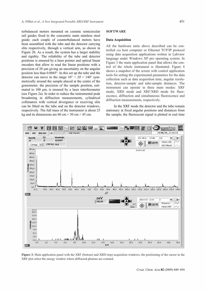
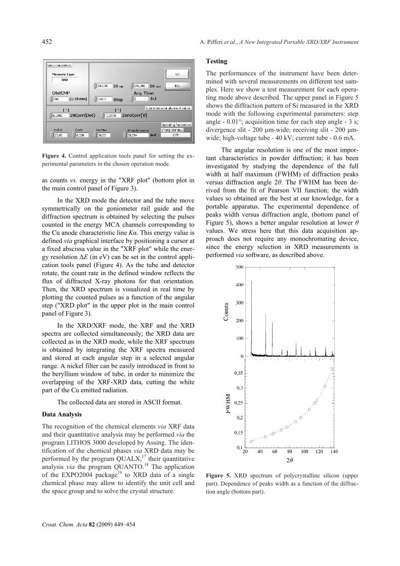
The performances of the instrument have been deter-mined with several measurements on different test sam-ples. Here we show a test measurement for each opera-ting mode above described. The upper panel in Figure 5 shows the diffraction pattern of Si measured in the XRD mode with the following experimental parameters: step angle - 0.01°; acquisition time for each step angle - 3 s; divergence slit - 200 μm-wide; receiving slit - 200 μm-wide; high-voltage tube - 40 kV; current tube - 0.6 mA.
The angular resolution is one of the most impor-tant characteristics in powder diffraction; it has been investigated by studying the dependence of the full width at half maximum (FWHM) of diffraction peaks versus diffraction angle 2θ. The FWHM has been de-rived from the fit of Pearson VII function; the width values so obtained are the best at our knowledge, for a portable apparatus. The experimental dependence of peaks width versus diffraction angle, (bottom panel of Figure 5), shows a better angular resolution at lower θ values. We stress here that this data acquisition ap-proach does not require any monochromating device, since the energy selection in XRD measurements is performed via software, as described above.
Figure 4. Control application tools panel for setting the ex-perimental parameters in the chosen operation mode.
Figure 5. XRD spectrum of polycrystalline silicon (upperpart). Dependence of peaks width as a function of the diffrac-tion angle (bottom part).
A. Pifferi et al., A New Integrated Portable XRD/XRF Instrument 453
Croat. Chem. Acta 82 (2009) 449–454
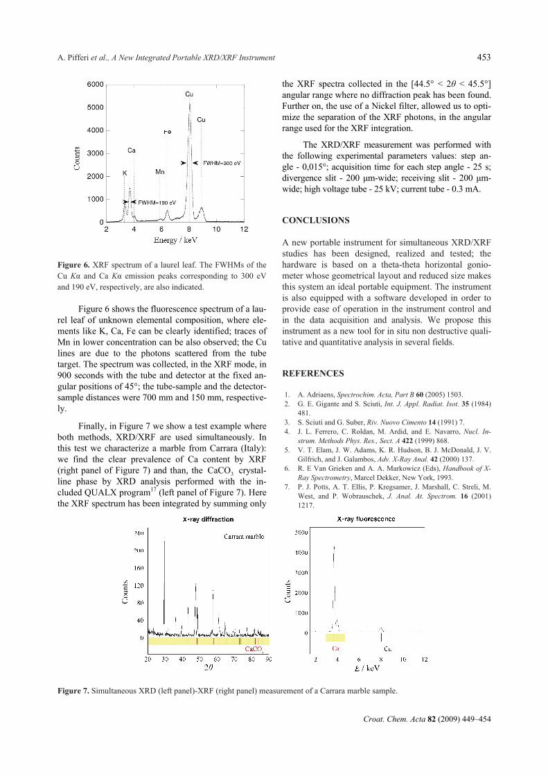
Figure 6 shows the fluorescence spectrum of a lau-rel leaf of unknown elemental composition, where ele-ments like K, Ca, Fe can be clearly identified; traces of Mn in lower concentration can be also observed; the Cu lines are due to the photons scattered from the tube target. The spectrum was collected, in the XRF mode, in 900 seconds with the tube and detector at the fixed an-gular positions of 45°; the tube-sample and the detector-sample distances were 700 mm and 150 mm, respective-ly.
Finally, in Figure 7 we show a test example where both methods, XRD/XRF are used simultaneously. In this test we characterize a marble from Carrara (Italy): we find the clear prevalence of Ca content by XRF (right panel of Figure 7) and than, the 3CaCO crystal-line phase by XRD analysis performed with the in-cluded QUALX program17 (left panel of Figure 7). Here the XRF spectrum has been integrated by summing only
the XRF spectra collected in the [44.5° < 2θ < 45.5°] angular range where no diffraction peak has been found. Further on, the use of a Nickel filter, allowed us to opti-mize the separation of the XRF photons, in the angular range used for the XRF integration.
The XRD/XRF measurement was performed with the following experimental parameters values: step an- gle - 0,015°; acquisition time for each step angle - 25 s; divergence slit - 200 μm-wide; receiving slit - 200 μm-wide; high voltage tube - 25 kV; current tube - 0.3 mA.
CONCLUSIONS
A new portable instrument for simultaneous XRD/XRF studies has been designed, realized and tested; the hardware is based on a theta-theta horizontal gonio-meter whose geometrical layout and reduced size makes this system an ideal portable equipment. The instrument is also equipped with a software developed in order to provide ease of operation in the instrument control and in the data acquisition and analysis. We propose this instrument as a new tool for in situ non destructive quali-tative and quantitative analysis in several fields.
REFERENCES
1. A. Adriaens, Spectrochim. Acta, Part B 60 (2005) 1503. 2. G. E. Gigante and S. Sciuti, Int. J. Appl. Radiat. Isot. 35 (1984)
481. 3. S. Sciuti and G. Suber, Riv. Nuovo Cimento 14 (1991) 7. 4. J. L. Ferrero, C. Roldan, M. Ardid, and E. Navarro, Nucl. In-
strum. Methods Phys. Res., Sect. A 422 (1999) 868. 5. V. T. Elam, J. W. Adams, K. R. Hudson, B. J. McDonald, J. V.
Gilfrich, and J. Galambos, Adv. X-Ray Anal. 42 (2000) 137. 6. R. E Van Grieken and A. A. Markowicz (Eds), Handbook of X-
Ray Spectrometry, Marcel Dekker, New York, 1993. 7. P. J. Potts, A. T. Ellis, P. Kregsamer, J. Marshall, C. Streli, M.
West, and P. Wobrauschek, J. Anal. At. Spectrom. 16 (2001) 1217.
Figure 6. XRF spectrum of a laurel leaf. The FWHMs of theCu Kα and Ca Kα emission peaks corresponding to 300 eVand 190 eV, respectively, are also indicated.
Figure 7. Simultaneous XRD (left panel)-XRF (right panel) measurement of a Carrara marble sample.

454 A. Pifferi et al., A New Integrated Portable XRD/XRF Instrument
Croat. Chem. Acta 82 (2009) 449–454
8. D. L. Bish and S. A. Howard, J. Appl. Crystallogr. 21 (1988) 86–91.
9. R. Cesareo, G. E. Gigante, P. Canegallo, A. Castellano, J. S. Iwanczyk, and A. Dabrowski, Nucl. Instrum. Methods Phys. Res., Sect. A 380 (1996) 440.
10. A. Longoni, C. Fiorini, P. Leutenegger, S. Sciuti, G. Fronterotta, L. Struder, and P. Lechner, Nucl. Instrum. Methods Phys. Res., Sect. A, 409 (1998) 407.
11. C. Ribbing, M. Andersson, K. Hjort, and H. Lundqvist, Rev. Sci. Instrum. 74 (2003) 3423.
12. F. P. Romano, G. Pappalardo, L. Pappalardo, S. Garaffo, R. Gigli, and A. Pautasso, X-Ray Spectrom. 35 (2006) 1.
13. Ch. Zarkadas and A. G. Karydas, Spectrochim. Acta, Part B 59 (2004) 1611.
14. S. Cornaby, A. Reyes-Mena, H. K. Pew, P. W. Moody, T.
Hughes, A. Strading, D. C. Turner, and L.V. Knight, Meas. Sci. Technol. 12 (2001) 676.
15. M. Uda, A. Ishizaki, R. Satoh, K. Okada, Y. Nakajima, D. Ya-mashita, K. Ohashi, Y. Sakuraba, A. Shimono, and D. Kojima, Nucl. Instrum. Methods Phys. Res., Sect. B 239 (2005) 77–84.
16. http://www.assing.it 17. A. Altomare, M. Camalli, C. Cuocci, C. Giacovazzo, A. G. G.
Moliterni, and R. Rizzi, J. Appl. Crystallogr. 41 (2008) 815–817. 18. A. Altomare, C. Burla, C. Giacovazzo, A. Gagliardi, A. G. G.
Moliterni, G. Polidori, and R. Rizzi, J. Appl. Crystallogr. 34 (2001) 392–397.
19. A. Altomare, M. Camalli, C. Cuocci, C. Giacovazzo, A. G. G. Moliterni, and R. Rizzi, J. Appl. Crystallogr. 37 (2004) 1025–1028.
SAŽETAK
Novi prijenosni XRD/XRF uređaj za nedestruktivnu analizu
Augusto Pifferi,a Gaetano Campi,b Carmelo Giacovazzob i Ettore Gobbic
aIstituto di Cristallografia, CNR, sezione di Monterotondo, Area della Ricerca di Roma - Montelibretti, P. O. Box 10, 00016 Monterotondo St.(RM), Italy
bIstituto di Cristallografia, CNR, via G. Amendola 122, 70126 Bari, Italy cAssing S. P. A. via E. Amaldi 14, 00016 Monterotondo (Roma), Italy
Predstavljen je novi prijenosni uređaj s mogućnošću difrakcije (XRD) i fluorescencije (XRF) rentgenskih zraka “in situ”. Oprema instrumenta zasnovana na Theta-Theta horizontalnom goniometru projektirana je i razvijena sa svrhom optimizacije stabilnosti i pouzdanosti takvih malih uređaja, koji prikupljaju XRF i XRD informacije. Si-multano prikupljanje, XRD i XRF podataka, postiže se uporabom Si detektora, koji broji fotone rentgenskih zraka raspršenih na uzorku kao funkciju energije i kutnog pomaka. Uređaj je opremljen i programskom podrškom koja omogućuje lakoću u prikupljanju podataka i brzu karakterizaciju uzoraka.