Embed Size (px)
Citation preview

Deep Mining 2019 Conference Muldersdrift, 24–25 June 2019 The Southern African Institute of Mining and Metallurgy
205
A new method to evaluate dynamic bolts and the development of a new dynamic rock bolt
B. Darlington, M. Rataj and W. Roach
Sandvik Mining and Rock Technology
Until science advances our current understanding of the demands and capacity of ground support, empirical design, rather than scientific methods, must be used. When considering ground support capacity, the industry has developed a significant database of laboratory dynamic tests on rock bolts. However, a methodology has not yet been developed to translate these laboratory test results into the in situ dynamic capacity of ground support systems. Recent development and implementation of in situ testing of dynamic bolts, provides a significant improvement in evaluation and interpretation of test results. In situ testing is carried out using a portable dynamic test rig (DTR), which simulates a seismic event through a dynamic impulse applied to a test bolt. This new tool also provides an opportunity to study the effects of mining progression on bolt performance. The DTR was utilised to test the recently developed D47 MDX bolt. The 47 mm diameter MDX bolt was tested at various hard rock mines in Australia with a typical 25 kJ dynamic impulse, causing bolt displacement typically between 100mm to 150 mm.
INTRODUCTION As the mining industry matures, near surface deposits become depleted, resulting in a need to mine at increasing depths. Some mines are exceeding 2 km in Australia, 3 km in Canada and even 4 km in South Africa (Potvin and Wesseloo, 2013). With these increasing depths come many risks, including an increase in in situ stresses and the likelihood of seismic events. The increase in in situ stresses can be managed with conventional ground control methods (Stacey, 2012); however, managing the increased seismic risk is a challenge for reinforcement systems. Developing new reinforcement systems is not a simple process, particularly when evaluating the performance of new systems for dynamic applications. Traditionally, laboratory testing was used to evaluate the performance of dynamic ground support systems. However, this method presented limitations with sample preparation, the test environment and correlation with mine-specific conditions. Alternate methods of ground support system evaluation include seismic event simulation through blasting and passive monitoring with back analysis of case studies (Hadjigeorgiou and Potvin, 2007). Simulating seismic events through blasting has inherent issues, including large infrastructure requirements, preparation time and preparation cost. This test method is suitable for simulating energy acting on an underground excavation during a seismic event (Stacey, 2018). However, as with utilising a passive monitoring approach, quantitative results are very difficult to achieve, as both methods are subjective.
https://papers.acg.uwa.edu.au/p/1952_16_Darlington/
206
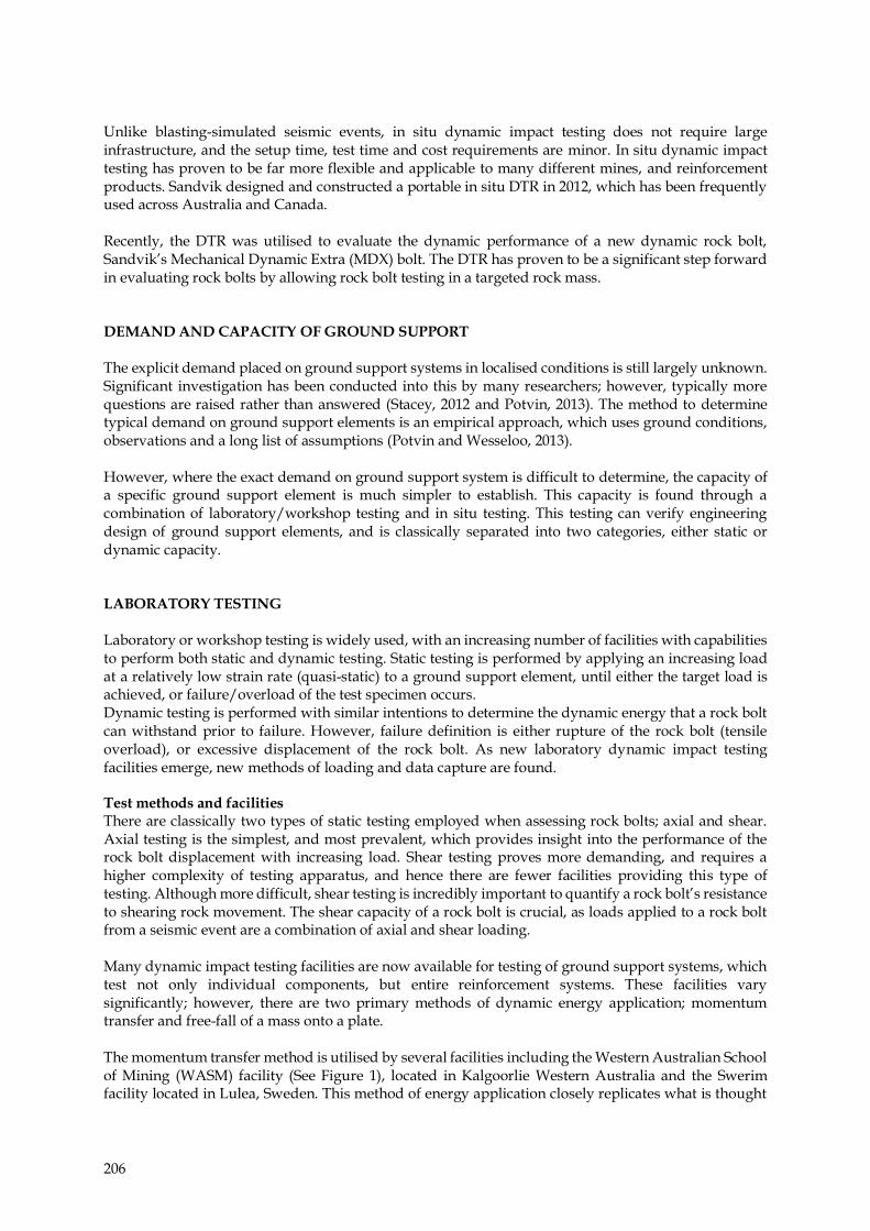
Unlike blasting-simulated seismic events, in situ dynamic impact testing does not require large infrastructure, and the setup time, test time and cost requirements are minor. In situ dynamic impact testing has proven to be far more flexible and applicable to many different mines, and reinforcement products. Sandvik designed and constructed a portable in situ DTR in 2012, which has been frequently used across Australia and Canada. Recently, the DTR was utilised to evaluate the dynamic performance of a new dynamic rock bolt, Sandvik’s Mechanical Dynamic Extra (MDX) bolt. The DTR has proven to be a significant step forward in evaluating rock bolts by allowing rock bolt testing in a targeted rock mass. DEMAND AND CAPACITY OF GROUND SUPPORT The explicit demand placed on ground support systems in localised conditions is still largely unknown. Significant investigation has been conducted into this by many researchers; however, typically more questions are raised rather than answered (Stacey, 2012 and Potvin, 2013). The method to determine typical demand on ground support elements is an empirical approach, which uses ground conditions, observations and a long list of assumptions (Potvin and Wesseloo, 2013). However, where the exact demand on ground support system is difficult to determine, the capacity of a specific ground support element is much simpler to establish. This capacity is found through a combination of laboratory/workshop testing and in situ testing. This testing can verify engineering design of ground support elements, and is classically separated into two categories, either static or dynamic capacity. LABORATORY TESTING Laboratory or workshop testing is widely used, with an increasing number of facilities with capabilities to perform both static and dynamic testing. Static testing is performed by applying an increasing load at a relatively low strain rate (quasi-static) to a ground support element, until either the target load is achieved, or failure/overload of the test specimen occurs. Dynamic testing is performed with similar intentions to determine the dynamic energy that a rock bolt can withstand prior to failure. However, failure definition is either rupture of the rock bolt (tensile overload), or excessive displacement of the rock bolt. As new laboratory dynamic impact testing facilities emerge, new methods of loading and data capture are found. Test methods and facilities There are classically two types of static testing employed when assessing rock bolts; axial and shear. Axial testing is the simplest, and most prevalent, which provides insight into the performance of the rock bolt displacement with increasing load. Shear testing proves more demanding, and requires a higher complexity of testing apparatus, and hence there are fewer facilities providing this type of testing. Although more difficult, shear testing is incredibly important to quantify a rock bolt’s resistance to shearing rock movement. The shear capacity of a rock bolt is crucial, as loads applied to a rock bolt from a seismic event are a combination of axial and shear loading. Many dynamic impact testing facilities are now available for testing of ground support systems, which test not only individual components, but entire reinforcement systems. These facilities vary significantly; however, there are two primary methods of dynamic energy application; momentum transfer and free-fall of a mass onto a plate. The momentum transfer method is utilised by several facilities including the Western Australian School of Mining (WASM) facility (See Figure 1), located in Kalgoorlie Western Australia and the Swerim facility located in Lulea, Sweden. This method of energy application closely replicates what is thought
207
to be the load transfer mechanism when a seismic wave encounters an underground excavation (Player et al, 2008a).
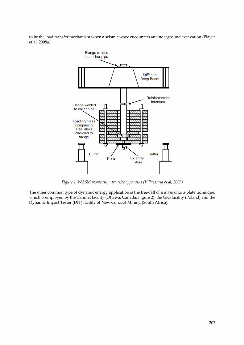
Figure 1. WASM momentum transfer apparatus (Villaescusa et al, 2005) The other common type of dynamic energy application is the free-fall of a mass onto a plate technique, which is employed by the Canmet facility (Ottawa, Canada, Figure 2), the GIG facility (Poland) and the Dynamic Impact Tester (DIT) facility of New Concept Mining (South Africa).
208
Figure 2. Canmet dynamic testing facility (Marambio et al, 2018) RESULTS DATABASE Laboratory test facilities have developed a large database of dynamic impact results from tests performed over the past several decades. These results are very comprehensive when it comes to resin or cement grouted bolts, as laboratory facilities are ideal for testing the performance of the connection between the yielding element and resin or cement grout. However, when testing friction type bolts, the database is relatively incomplete, due to the limitations associated with sample preparation. The results database is readily available, and has been published in many forms, Potvin (2017). See Figure 3 for a summary of a portion of these test result.

209
Figure 3. A summary of Laboratory dynamic test results (Potvin, 2017) CORRELATION TO IN SITU PERFORMANCE Laboratory facilities utilise two different sample preparation methods; cement aggregate filled steel tubes, or over-cored rock samples assembled within steel tubes. The first method is the most efficient regarding cost and time and is solely utilised by several facilities. This method is ideal for laboratory testing, as it ensures a constant test medium with controlled properties. Unfortunately, this artificial rock does not represent underground mining, where rock masses vary significantly.
210
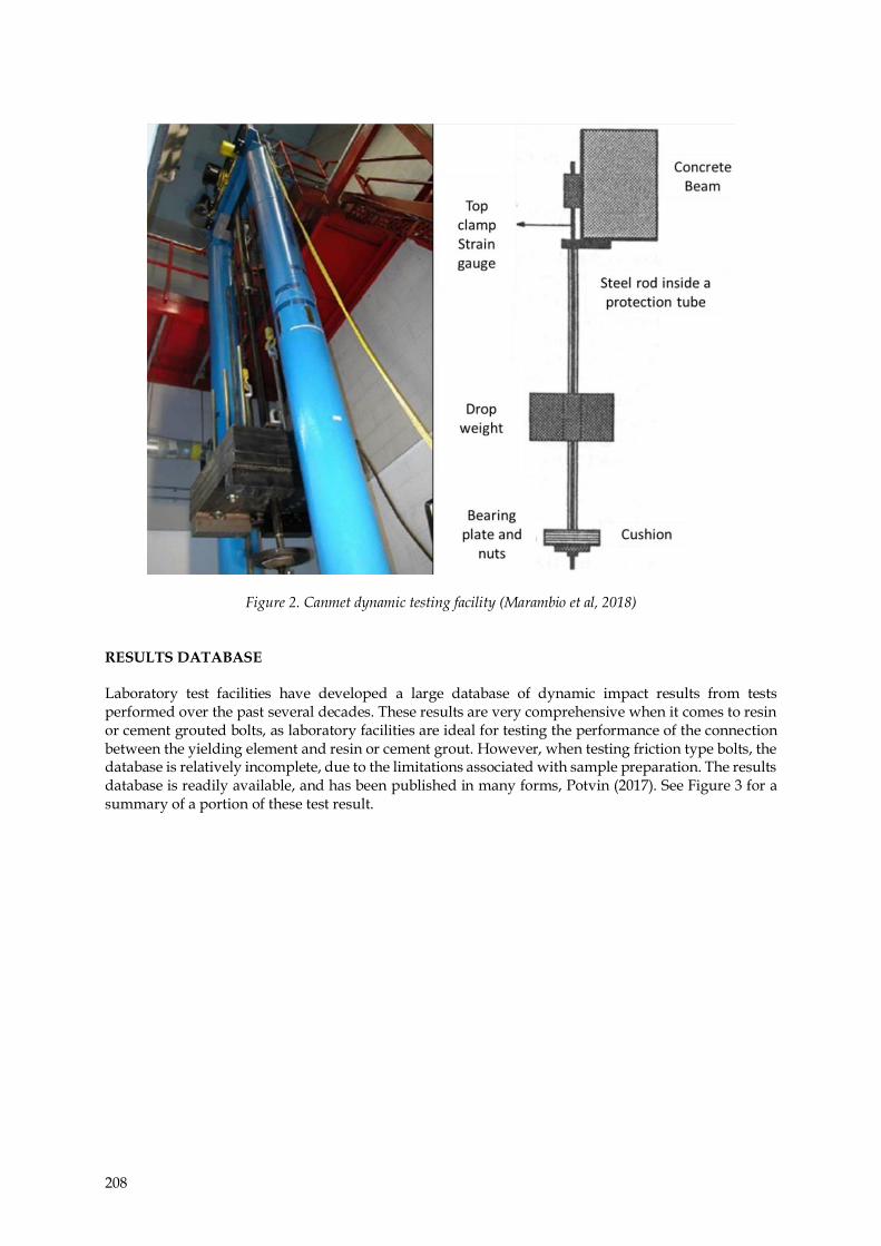
The major issue with utilising a cement/grout aggregate for laboratory testing develops when testing friction style bolts, which rely purely on the connection between bolt and “rock” for dynamic performance. A relatively thin-wall steel pipe filled with cement aggregate (see figure 4) will differ in many ways to a large section of rock mass. These differences include confinement on the bore hole, surface roughness/friction of the borehole and straightness of the bore-hole.
Figure 4. Simulated borehole in this walled steel pipe (Player, 2008b)
A thin walled steel pipe filled with concrete will not provide the same confinement to outward forces, such as from a friction bolt or a wedge anchor mechanism. Likewise, the straightness and surface roughness of the simulated bore hole will vary from that found in an underground mine. Laboratory testing applies dynamic energy axially to the test specimen, where this is very rarely the case in underground mines. The loading of a bolt subject to a seismic event is a combination of axial and shear loading, which is a result of the installation angle relative to the rock face and the direction in which the energy wave approaches the excavation. IN SITU TESTING In contrast to laboratory testing, until recently, very little in situ dynamic testing has been conducted. This is due to the difficulties involved with adapting existing laboratory apparatus to the underground environment. Where laboratory testing is ideal for benchmark testing, in situ dynamic testing provides invaluable information on the performance of ground support elements in specific strata conditions. Testing ground support elements in situ offers an opportunity to analyse variations related to test sample installation. These can include; machine differences, operator methods (and errors), orientation to the rock face and, most important, variations in ground conditions. Additional testing benefits of in situ testing include delayed testing, where samples are tested sometime after installation. This test method provides insight into the effects of mining progression, localised ground movement and exposure to ground water on the dynamic performance of ground support elements.

211
SANDVIK APPARATUS DEVELOPMENT
In 2012, Sandvik identified the need for an in situ testing apparatus and the associated benefits of providing this type of testing. Therefore, Sandvik designed and constructed a portable in situ dynamic test rig, capable of being transported to any mine site, and testing any rock bolt in any rock type. An initial prototype apparatus was utilised in association with Mikula Geotechnics and Rocktech for the introduction of the Sandvik Mechanical Dynamic (MD) bolt at Mt Charlotte Gold Mine in 2013 (Carlton et al, 2013). The results from this testing further highlighted the need for a fully functional in situ dynamic test rig. The first complete DTR was used between 2013 to 2016 to verify the performance of the Sandvik MD bolt and other rock bolts at 5 sites across Australia. During this test period, several design improvements increased both the speed and ease of testing. The DTR apparatus utilises the free-fall of a mass onto a plate energy application technique and can apply dynamic energy up to 38 kJ in a single impact. Typically, test regimes apply single dynamic impacts to each test bolt; however, multiple impacts on one bolt are possible, and planning is underway for future testing. The applied energy is easily modified, similar to laboratory facilities, by adjusting the drop mass or drop height; however, the impact velocity is typically maintained between 5.2 m/s to 5.7 m/s. The DTR, like any laboratory facility, is capable of both non-destructive and destructive dynamic testing. In both testing scenarios the DTR captures the load applied to the bolt and displacement of the bolt. A piezoelectric load cell measures the load applied to the bolt and accelerometer data allows calculation of bolt displacement. Both sensors record at 25 kHz and link directly to a control box, which also activates the release mechanism. The drop mass is released using a remotely operated control, with a maximum safe release distance of 50 m. The method to connect the DTR to the rock bolt is important, as this minimises the time required to test each rock bolt and contains the sensors. The current embodiment (See Figure 5) is in the form of a patented two-part claw assembly, which contains domed connections top and bottom. These domed connections allow for variations in bolt installation angle (Up to 10° from vertical). In this configuration, the DTR can apply not only axial loads, but also a portion of shear and bending loads, which closer represents loading during a seismic event. Typically, bolt installation angle is limited to 5°; however, a study on the influence of bolt installation angle to dynamic performance is planned for future testing.

212
Figure 5. Sandvik Dynamic Test Rig
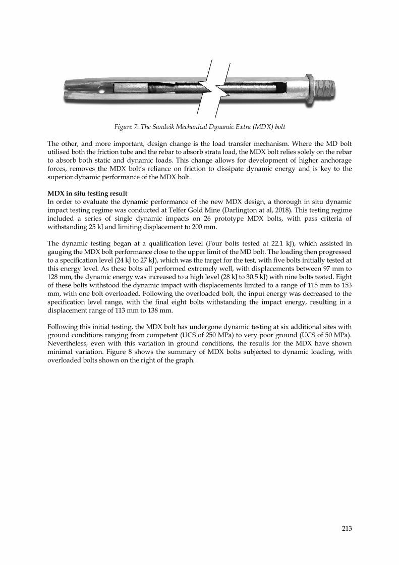
UTILISATION TO TEST SANDVIK MDX BOLT PERFORMANCE From 2016, the Sandvik DTR assisted in the development of Sandvik’s new dynamic rock bolt, the Mechanical Dynamic Extra (MDX) bolt. The MDX bolt was developed to provide more consistent in situ dynamic performance when subjected to dynamic energy in excess of 22 kJ. The design platform of the MDX bolt comprises a 47 mm diameter friction bolt tube and wedge expansion system similar to the MD bolt (See Figure 6 and Figure 7). The key differences between the MD and MDX bolts are the wedge assembly and the load transfer mechanisms. The wedge assembly design review increased the maximum tube expansion to 60 mm, which has a dual advantage. The MDX bolt is suitable for a greater range of ground condition and this wedge system assists in dissipating dynamic energy.
Figure 6. The Sandvik Mechanical Dynamic (MD) bolt
213
Figure 7. The Sandvik Mechanical Dynamic Extra (MDX) bolt
The other, and more important, design change is the load transfer mechanism. Where the MD bolt utilised both the friction tube and the rebar to absorb strata load, the MDX bolt relies solely on the rebar to absorb both static and dynamic loads. This change allows for development of higher anchorage forces, removes the MDX bolt’s reliance on friction to dissipate dynamic energy and is key to the superior dynamic performance of the MDX bolt. MDX in situ testing result In order to evaluate the dynamic performance of the new MDX design, a thorough in situ dynamic impact testing regime was conducted at Telfer Gold Mine (Darlington at al, 2018). This testing regime included a series of single dynamic impacts on 26 prototype MDX bolts, with pass criteria of withstanding 25 kJ and limiting displacement to 200 mm. The dynamic testing began at a qualification level (Four bolts tested at 22.1 kJ), which assisted in gauging the MDX bolt performance close to the upper limit of the MD bolt. The loading then progressed to a specification level (24 kJ to 27 kJ), which was the target for the test, with five bolts initially tested at this energy level. As these bolts all performed extremely well, with displacements between 97 mm to 128 mm, the dynamic energy was increased to a high level (28 kJ to 30.5 kJ) with nine bolts tested. Eight of these bolts withstood the dynamic impact with displacements limited to a range of 115 mm to 153 mm, with one bolt overloaded. Following the overloaded bolt, the input energy was decreased to the specification level range, with the final eight bolts withstanding the impact energy, resulting in a displacement range of 113 mm to 138 mm.
Following this initial testing, the MDX bolt has undergone dynamic testing at six additional sites with ground conditions ranging from competent (UCS of 250 MPa) to very poor ground (UCS of 50 MPa). Nevertheless, even with this variation in ground conditions, the results for the MDX have shown minimal variation. Figure 8 shows the summary of MDX bolts subjected to dynamic loading, with overloaded bolts shown on the right of the graph.

214
Figure 8. Absorbed energy Vs displacement summary for all MDX bolt tests
CONCLUSION Currently, there is a variety of laboratory dynamic testing facilities available for benchmarking dynamic ground reinforcement products. These facilities have established a database of reinforcement performance under dynamic loading conditions. However, it is difficult to correlate these results to underground conditions. The Sandvik DTR expands the capabilities of dynamic testing, taking a significant step forward to provide dynamic performance data for ground reinforcement products in underground mine conditions. This method of testing is not only quick and cost effective, it also opens avenues for evaluating the influence of mining progression on ground reinforcement systems. The planned delayed testing at a specific time after installation will provide additional insights for further improvements of ground reinforcement systems. The Sandvik DTR was successfully utilised as a development tool for the new MDX bolt, evaluating the performance of this bolt in seven different rock types. The performance of the MDX bolt remains consistent, with a displacement range of 105 mm to 161 mm, while absorbing dynamic energy between 25 kJ and 30 kJ.
0
10
20
30
0 50 100 150 200 250 300
Ab
sorb
ed
En
erg
y (k
J)
Displacement (mm)
MDX Bolt Dynamic Performance
MDX Mine E-UCS 240 MPa MDX Mine F-UCS 127 MPa MDX Mine G-UCS 100 MPa
MDX Mine H-UCS 50 MPa MDX Mine I-UCS 215 MPa MDX Mine J-UCS 192 MPa
MDX Mine K-UCS 200 MPa
Overloaded bolts
215
REFERENCES Carlton, R., Mikula, P., Darlington, B. 2013. In situ dynamic drop testing of the MD bolt at Mt Charlotte
Gold Mine. Proceedings of the Seventh International Symposium on Ground Support in Mining and Underground Construction 2013. Potvin, Y. and Brady, B. (eds). Australian Centre for
Geomechanics, Perth. pp. 207-219.
Darlington, B., Rataj, M., Balog, G., Barnett, B. 2018. Development of the MDX Bolt and in situ dynamic
testing at Telfer Gold Mine. Proceedings of the 3rd international conference on Rock Dynamics and Applications (RocDyn-3) 2018. Li, C., Li, X. and Zhang, Z. (eds). CRC Press, Leiden. pp. 403-408.
Hadjigeorgiou, J., Potvin, Y. 2007 .Overview of Dynamic testing of Ground Support. Proceeding of the 4th
International Seminar on Deep and high stress mining 2007. Y Potvin (eds). Australian Centre for Geomechanics, Perth, pp. 349-371.
Li, C.C., Stjern, G., Myrvang, A. 2014. A review on the performance of conventional and energy-
absorbing rockbolts. Journal of Rock Mechanics and Geotechnical Engineering, 6 (2014), 315-327.
Marambio, E., Vallejos, JA., Burgos, L., Gonzalez, C., Castro, L., Saure, JP,. Urzua, J. 2018. Numerical
modelling of dynamic testing for rock reinforcement used in underground excavations. Proceeding of the 4th International symposium on Block and Sublevel Caving 2018. Y Potvin (eds).
Australian Centre for Geomechanics, Perth.
Player, J., Villaescusa, E., Thompson, A. 2008. An Examination of Dynamic Test Facilities. Australian
Mining Technology Conference 2008.
Player, J., Thompson, A., Villaescusa, E. 2008. Dynamic Testing of Reinforcing Systems. Proceeding of the
6th International Symposium on Ground Support in Mining and Civil Engineering Construction 2008.
SAIMM, SANIRE and ISRM. pp. 597-622.
Potvin, Y., Wesseloo, J. 2013. Towards an understanding of dynamic demand on ground support.
Proceedings of the Seventh International Symposium on Ground Support in Mining and Underground Construction 2013. Potvin, Y. and Brady, B. (eds). Australian Centre for Geomechanics, Perth. pp.
287-304.
Potvin, Y. 2017. The need for new technology to optimise the engineering of ground support systems in
underground mines. Proceedings of the First International conference on Ground Mining Technology 2017. Potvin, Y. and Hudyma, M (eds). Australian Centre for Geomechanics, Perth.
Shirzadegan, S., Nordlund, E., Zhang, (2016). In situ dynamic testing of rock support at LKAB
Kiirunavaara mine. Proceedings of the 8th International Symposium on Ground Support in Mining and Underground Construction 2016. Nordlund, E., Jones, T.H., and Eitzenberger, A. (eds). Lulea university of Technology, Sweden. pp. 515-526.
Shirzadegan, S., Nordlund, E., Zhang, P. 2016. Large Scale Dynamic Testing of Rock Support System at
Kiirunavaara Underground Mine. Rock Mechanics and Rock Engineering (2016). 49:2773.
Stacey, T. 2012 .A philosophical view on the testing of rock support for rockburst conditions. Journal of
the Southern African Institute of Mining and Metallurgy, vol. ISSN 2411-9717, 112, no. 8, pp. 703-710.
Stacey, T. 2018. A personal review of South African rockburst research, experience and lessons learnt.
Proceedings of the 4th Australasian Ground Control in Mining Conference (AusRock 2018). The
Australasian Institute of Mining and Metallurgy. pp. 5-16.

216
Villaescusa, E., Thompson, A., Player, J. 2005. Dynamic Testing of Rock Reinforcement Systems.
Australian Mining Technology Conference 2005.
Bradley Darlington
R&D Engineer – Bolting Sandvik Mining and Rock Technology Bradley Darlington is an R&D design Engineer at Sandvik Mining and Rock Technology. He completed his Bachelor of Engineering (Mechanical) in 2009, and has worked in Sandvik’s Bolting division for the past 7 years. Over this time, he has been involved with designing and implementing new products into the ground support market, and managed the design, development and use of the first ever in-situ dynamic test rig.