Embed Size (px)
Citation preview
A. Abu-Odeh, D. Albin, D. Olson
1
A New MASH Compliant Guardrail System for Placement on Slope 1 2
-by A. Y. Abu-Odeh, R. B. Albin, D. Olson 3 4 5 6
Word count: 3,506 (text) + 4,000 (14 figures+2 tables) = 7,506 7 First Submission: 1st August 2012 8 Second Revised Submission: 15 November 2012 9
10 Authors: 11 1. Akram Y. Abu-Odeh 12 Research Scientist 13 Texas Transportation Institute, Texas A&M University system, College Station, Texas 77843 14 Phone: 1-979-862-3379 15 Fax:1-979-845-6107 16 Email: [email protected] 17
18 2. Richard B. (Dick) Albin 19 Safety Engineer 20 Federal Highway Administration 21 Resource Center Safety and Design Technical Services Team 22 711 S. Capitol Way, Suite 501 23 Olympia, WA 98501-1284 24 Phone: 1-303-550-8804 25 Email: [email protected] 26 27
28 3. Dave Olson 29 Design Policy, Standards, 30 & Research Manager 31 Washington Department of Transportation 32 P. O. Box 47329 Olympia, WA 98504-7329 33 Phone: 1-360-705-7952 34 Email: [email protected] 35 36 37
38 39
TRB 2013 Annual Meeting Paper revised from original submittal.
A. Abu-Odeh, D. Albin, D. Olson
2
Abstract 1 2
The 2002 American Association of State Highway and Transportation Officials (AASHTO) 3 Roadside Design Guide recommends that a w-beam guardrail is installed with its back 4 positioned 2 ft in front of a slope break. In rolling and mountainous terrain or in locations with 5 restrictive environmental conditions, it is often difficult to provide this distance. As a result, 6 designers must evaluate the trade-offs between a reduced shoulder width and guardrail 7 installations that are less than optimal. In many instances, a guardrail is installed with longer 8 posts to provide adequate soil embedment. In the most restrictive site conditions, the post 9 lengths are excessively long which complicate system installation and maintenance repairs. 10
The research team used crash simulation and finite element analysis, followed by full scale 11 crash testing to explore system performance with standard w-beam guardrail components. The 12 project focused on designs that minimized post length. A 31-inch high w-beam guardrail system 13 with 8 foot long posts, spaced 6 ft- 3 inches on centers met MASH test level 3 criteria when 14 placed with the face of the rail over the slope break point on a 2H:1V fill slope. 15 16
17 18
Keywords: MASH, Guardrails, placement, slopes, simulation. 19 20
TRB 2013 Annual Meeting Paper revised from original submittal.
A. Abu-Odeh, D. Albin, D. Olson
3
INTRODUCTION 1
In rolling or mountainous terrain, or in areas with restrictive environmental conditions, it is 2 often difficult to provide a sufficient width behind the guardrail posts for a typical w-beam 3 guardrail (SGR04a). The 2002 AASHTO Roadside Design Guide specifies a minimum desirable 4 dimension of 2’ from the back of the post to the slope break point on a fill slope. This width 5 behind the post offers soil resistance to post rotation that is similar to the conditions on flat 6 terrain. This approach provides consistency in guardrail performance. 7
In rolling or mountainous terrain, providing additional width for the roadway cross section 8 often results in greater fill heights, which may extend beyond the available right of way. In 9 many environmentally sensitive areas, minimizing encroachment into the sensitive area is a 10 strategy utilized in mitigating environmental impacts. Many states have approached this issue by 11 extending guardrail post length and/or decreasing the post spacing along with reducing the 12 dimension behind the guardrail post. Some of these designs have not been fully crash tested. In 13 some instances, states have used posts as long as 11 ft which makes post installation and 14 maintenance repairs more difficult. 15
This research’s objective was to utilize standard w-beam guardrail components in the 16 development of a w-beam guardrail system suitable for placement at the top of a 2H:1V fill 17 slope. While it was recognized that longer posts would be necessary, the research focused on 18 minimizing post length to the greatest extent possible. Initial development efforts targeted a w-19 beam guardrail system with a 27-inch mounting height to the top of the rail. 20
The 27-inch high system was evaluated through bogie testing, computer simulation, and full 21 scale crash testing under NCHRP Report 350 criteria. During the full scale crash test, the pickup 22 overturned after having been restrained and redirected by the guardrail system. Post crash 23 analysis explored other design options, with the project sponsors ultimately electing to pursue 24 this design using a 31-inch high w-beam guardrail system to increase vehicle stability. The 25 timing of this redesign coincided with the adoption of MASH criteria, and the sponsors elected to 26 pursue the project in accordance with MASH guidance. 27
BACKGROUND 28
The 2002 AASHTO Roadside Design Guide recommends that a guardrail is to be installed 29 with its back positioned 2 feet in front of a slope break. This placement provides sufficient width 30 behind the post for the soil to resist excessive post rotation. Posts typically begin to rotate 31 through the soil until the vehicle is restrained or the soil resistance becomes so great that the post 32 yields, and the energy is transferred to the adjacent posts. If the post is placed too close to the 33 slope break point on steep fill slopes, the cohesive soil strength may be insufficient to restrict 34 post rotation. In rolling and mountainous terrain conditions or in locations with restrictive 35 environmental conditions, it is difficult to provide this distance. As a result, designers must 36 evaluate the trade-offs between a reduced shoulder width and guardrail installations with longer 37 posts to provide adequate soil embedment. Some states have utilized designs with posts up to 38 11 ft long. These excessively long posts complicate system installation and maintenance repairs. 39 Some designs currently in use may not have been fully crash tested. 40
The earliest known research with guardrail placement on slopes was conducted by ENSCO 41 Inc. (1993). This testing included pendulum tests on single posts, and was followed by 3 full 42 scale crash tests. Two tests were considered successful under NCHRP Report 230 (1981) 43 criteria, with a large sedan impacting the G4(1S) guardrail system installed at the break point of 44
TRB 2013 Annual Meeting Paper revised from original submittal.
A. Abu-Odeh, D. Albin, D. Olson
4
a 2H:1V slope. One of the systems used a configuration with 6-ft long posts, and the other 1 configuration utilized 7-ft long posts. The installation with 7-ft posts had a smaller deflection, 2 and less vehicle impact speed change than the installation with 6-ft long posts. 3
The Midwest Roadside Safety Facility (MwRSF) (2000) performed a battery of bogie tests, 4 and a test level 3 crash test of a 706 mm (27 3/4 inches) high guardrail system with 2,134 mm 5 (7-ft) long W 152x13.4 (W6x9) steel posts placed 952.5 mm (37.5 inches) on centers. This 6 system was successfully crash tested under NCHRP Report 350 criteria with the posts placed at 7 the break point on a 2H:1V fill slope. 8
Subsequently, researchers at MwRSF (2006) performed a battery of bogie tests with steel 9 posts ranging from 6-ft to 9-ft long, placed at the break point on a 2H:1V fill slope along with 10 two full scale crash tests. The 27-3/4 inch high rail design was unsuccessful according to MASH 11 test evaluation criteria. However, the 31-inch high guardrail system using the 9-ft long W6X9 12 steel posts placed 6 ft–3 inches on centers successfully passed MASH test 3-11 criteria 13
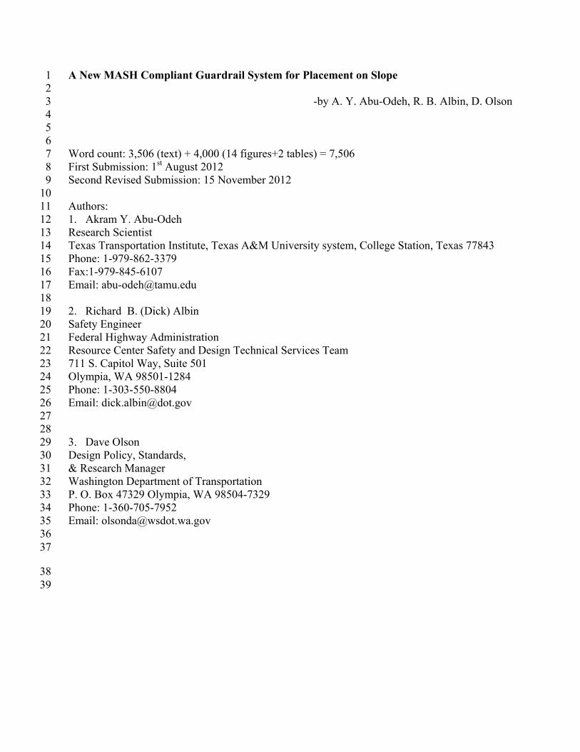
In 2008, Texas Transportation Institute (TTI) performed a series of bogie tests with steel 14 posts ranging from 6 ft to 9 ft long as well. Some were placed on a 2H:1V fill slope and some 15 were placed on a 1.5H:1V fill slope. All were placed 1 ft down from the slope break. Based on 16 these tests and subsequent simulations, a guardrail on a slope system was recommended for full 17 scale crash testing. The system was of a 27-inch high guardrail system with 8-ft long W6x9 steel 18 posts placed 37.5 inches on centers. This system was crash tested under NCHRP Report 350 TL-19 3-11 conditions with the posts placed at the break point on a 2H:1V fill slope 20
21 22
23 24
25 Figure 1 Impact sequential of TTI test 405160-4-1 26
27 The test was not successful according to NCHRP Report 350 test evaluation criteria. As 28
shown in Figure 1, the 2000P vehicle rolled on its side after it exited the guardrail system. 29 30
RESEARCH APPROACH 31
The research team focused on system development under MASH conditions since MASH 32 was adopted by AASHTO as crash testing guidelines in 2009. The research team developed a 33 detailed finite element model of the new design to investigate this design performance under 34
TRB 2013 Annual Meeting Paper revised from original submittal.
A. Abu-Odeh, D. Albin, D. Olson
5
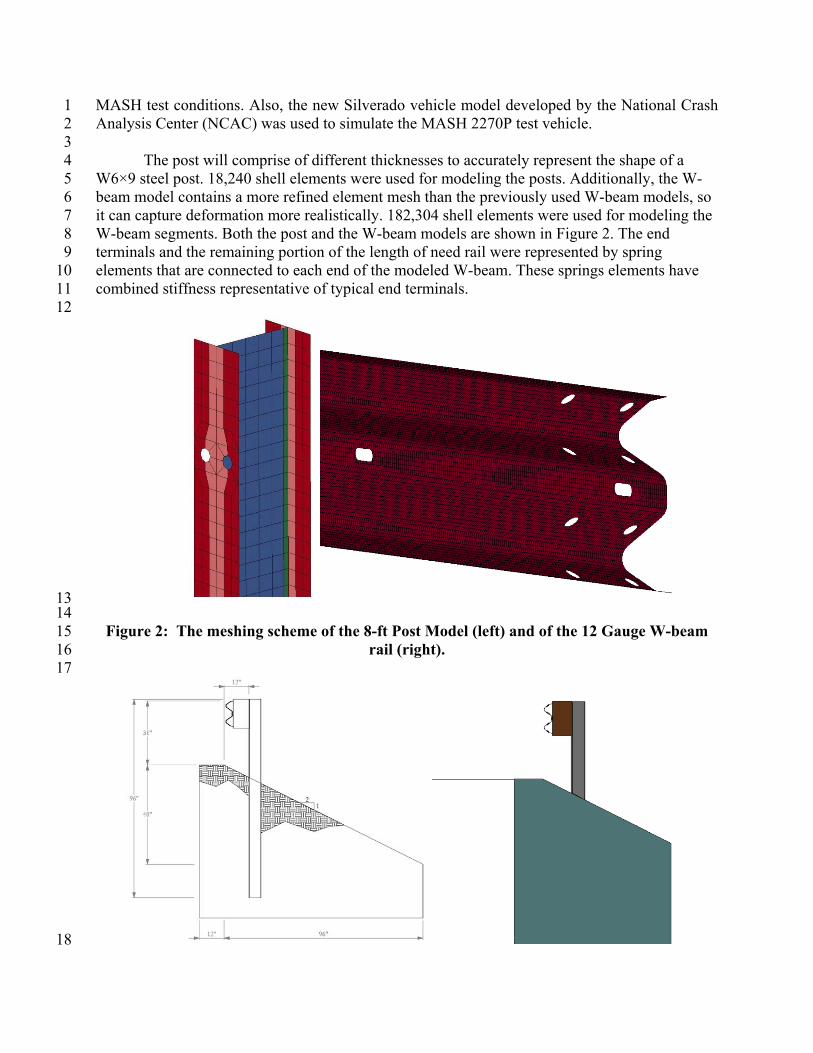
MASH test conditions. Also, the new Silverado vehicle model developed by the National Crash 1 Analysis Center (NCAC) was used to simulate the MASH 2270P test vehicle. 2
3 The post will comprise of different thicknesses to accurately represent the shape of a 4
W6×9 steel post. 18,240 shell elements were used for modeling the posts. Additionally, the W-5 beam model contains a more refined element mesh than the previously used W-beam models, so 6 it can capture deformation more realistically. 182,304 shell elements were used for modeling the 7 W-beam segments. Both the post and the W-beam models are shown in Figure 2. The end 8 terminals and the remaining portion of the length of need rail were represented by spring 9 elements that are connected to each end of the modeled W-beam. These springs elements have 10 combined stiffness representative of typical end terminals. 11
12
13 14
Figure 2: The meshing scheme of the 8-ft Post Model (left) and of the 12 Gauge W-beam 15 rail (right). 16
17
18
TRB 2013 Annual Meeting Paper revised from original submittal.
A. Abu-Odeh, D. Albin, D. Olson
6
1 Figure 3: Cross section of 31-inch guardrail system (left) and model (right). 2
The first design change was to increase the rail height from 27 inches to 31 inches 3 relative to the flat terrain. The cross-section views of the new system design and the model are 4 shown in Figure 3. 5
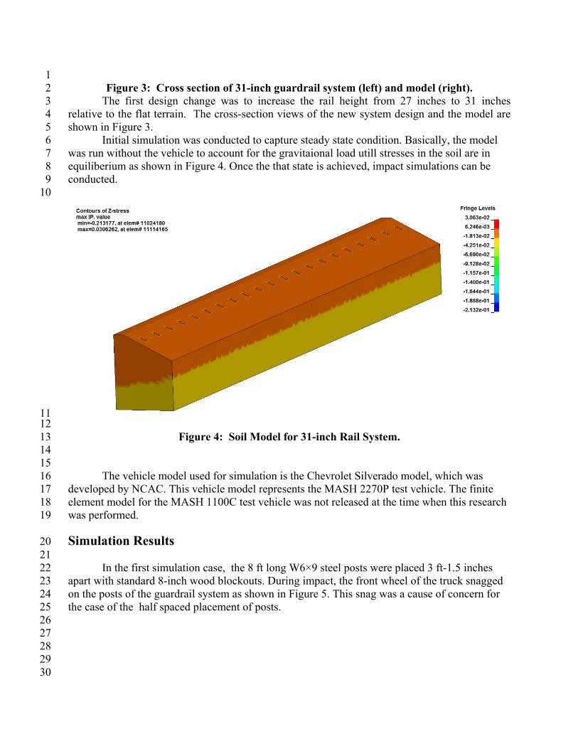
Initial simulation was conducted to capture steady state condition. Basically, the model 6 was run without the vehicle to account for the gravitaional load utill stresses in the soil are in 7 equiliberium as shown in Figure 4. Once the that state is achieved, impact simulations can be 8 conducted. 9 10
11 12
Figure 4: Soil Model for 31-inch Rail System. 13 14 15
The vehicle model used for simulation is the Chevrolet Silverado model, which was 16 developed by NCAC. This vehicle model represents the MASH 2270P test vehicle. The finite 17 element model for the MASH 1100C test vehicle was not released at the time when this research 18 was performed. 19
Simulation Results 20 21
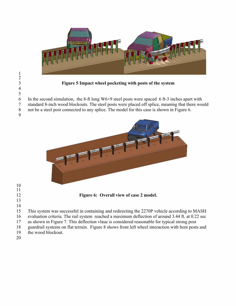
In the first simulation case, the 8 ft long W6×9 steel posts were placed 3 ft-1.5 inches 22 apart with standard 8-inch wood blockouts. During impact, the front wheel of the truck snagged 23 on the posts of the guardrail system as shown in Figure 5. This snag was a cause of concern for 24 the case of the half spaced placement of posts. 25
26 27 28 29 30
TRB 2013 Annual Meeting Paper revised from original submittal.
A. Abu-Odeh, D. Albin, D. Olson
7
1 2
Figure 5 Impact wheel pocketing with posts of the system 3 4 5
In the second simulation, the 8-ft long W6×9 steel posts were spaced 6 ft-3 inches apart with 6 standard 8-inch wood blockouts. The steel posts were placed off splice, meaning that there would 7 not be a steel post connected to any splice. The model for this case is shown in Figure 6. 8
9
10 11
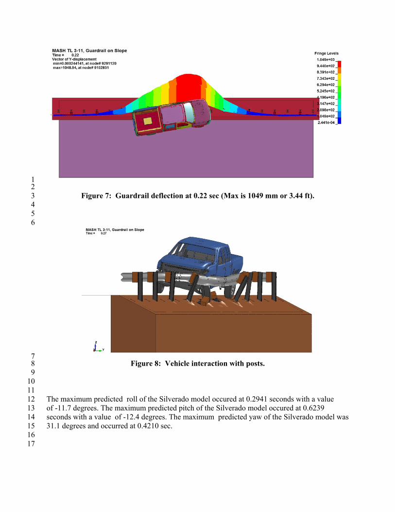
Figure 6: Overall view of case 2 model. 12 13 14 This system was successful in containing and redirecting the 2270P vehicle according to MASH 15 evaluation criteria. The rail system reached a maximum deflection of around 3.44 ft. at 0.22 sec 16 as shown in Figure 7. This deflection vlaue is considered reasonable for typical strong post 17 guardrail systems on flat terrain. Figure 8 shows front left wheel interaction with bent posts and 18 the wood blockout. 19 20
TRB 2013 Annual Meeting Paper revised from original submittal.
A. Abu-Odeh, D. Albin, D. Olson
8
1 2
Figure 7: Guardrail deflection at 0.22 sec (Max is 1049 mm or 3.44 ft). 3 4 5
6
7 Figure 8: Vehicle interaction with posts. 8
9 10 11 The maximum predicted roll of the Silverado model occured at 0.2941 seconds with a value 12 of -11.7 degrees. The maximum predicted pitch of the Silverado model occured at 0.6239 13 seconds with a value of -12.4 degrees. The maximum predicted yaw of the Silverado model was 14 31.1 degrees and occurred at 0.4210 sec. 15 16
17
TRB 2013 Annual Meeting Paper revised from original submittal.
A. Abu-Odeh, D. Albin, D. Olson
9
Full Scale Crash Tests 1
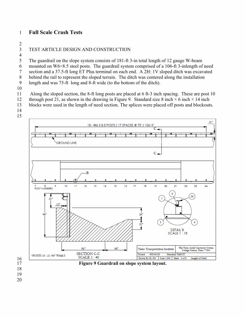
2 TEST ARTICLE DESIGN AND CONSTRUCTION 3 4 The guardrail on the slope system consists of 181-ft 3-in total length of 12 gauge W-beam 5 mounted on W6×8.5 steel posts. The guardrail system comprised of a 106-ft 3-inlength of need 6 section and a 37.5-ft long ET Plus terminal on each end. A 2H: 1V sloped ditch was excavated 7 behind the rail to represent the sloped terrain. The ditch was centered along the installation 8 length and was 75-ft long and 8-ft wide (to the bottom of the ditch). 9 10 Along the sloped section, the 8-ft long posts are placed at 6 ft-3 inch spacing. These are post 10 11 through post 21, as shown in the drawing in Figure 9. Standard size 8 inch × 6 inch × 14 inch 12 blocks were used in the length of need section. The splices were placed off posts and blockouts. 13 14 15
16 Figure 9 Guardrail on slope system layout. 17
18 19 20
TRB 2013 Annual Meeting Paper revised from original submittal.
A. Abu-Odeh, D. Albin, D. Olson
10
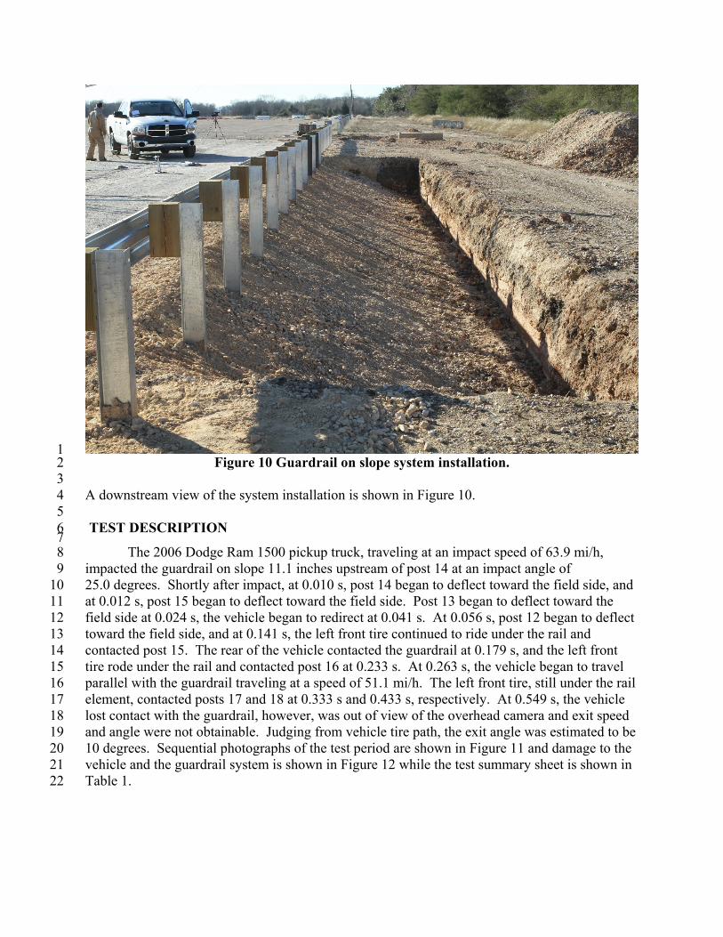
1 Figure 10 Guardrail on slope system installation. 2
3 A downstream view of the system installation is shown in Figure 10. 4
5 TEST DESCRIPTION 6 7
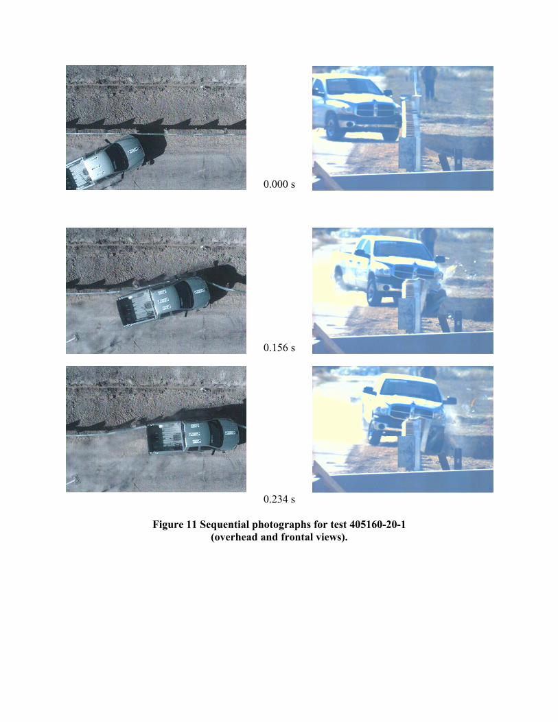
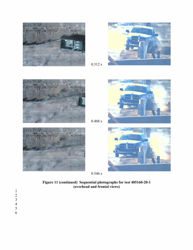
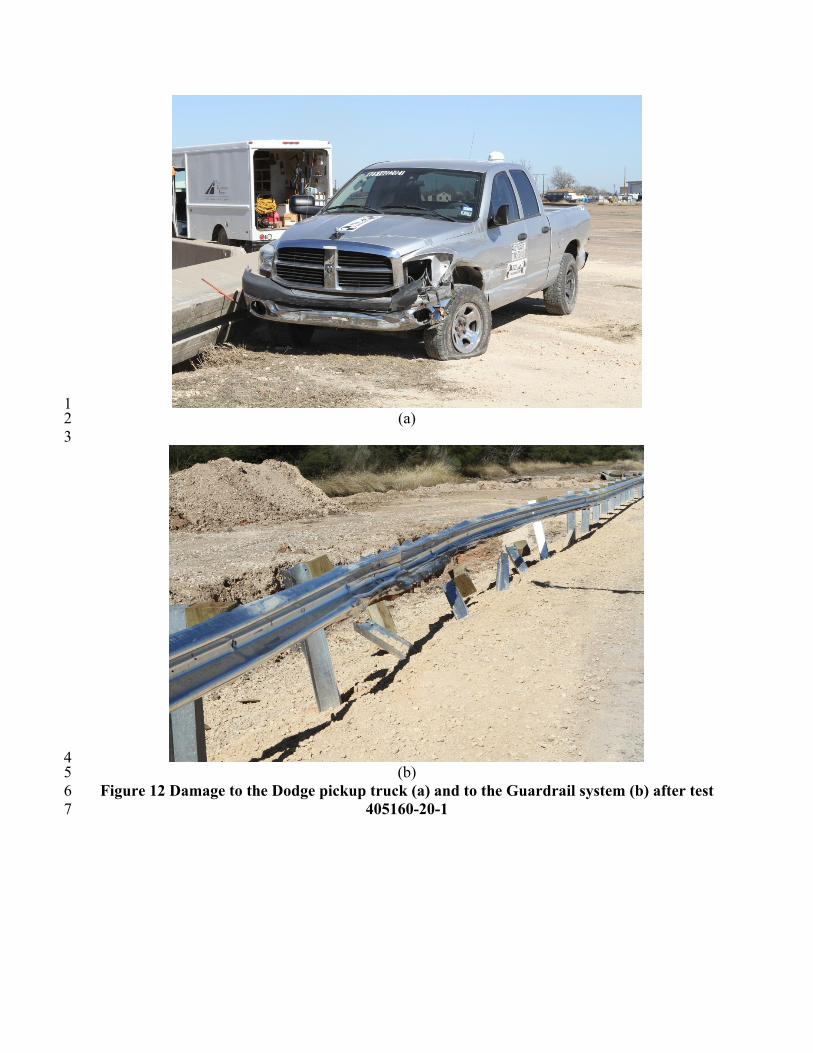
The 2006 Dodge Ram 1500 pickup truck, traveling at an impact speed of 63.9 mi/h, 8 impacted the guardrail on slope 11.1 inches upstream of post 14 at an impact angle of 9 25.0 degrees. Shortly after impact, at 0.010 s, post 14 began to deflect toward the field side, and 10 at 0.012 s, post 15 began to deflect toward the field side. Post 13 began to deflect toward the 11 field side at 0.024 s, the vehicle began to redirect at 0.041 s. At 0.056 s, post 12 began to deflect 12 toward the field side, and at 0.141 s, the left front tire continued to ride under the rail and 13 contacted post 15. The rear of the vehicle contacted the guardrail at 0.179 s, and the left front 14 tire rode under the rail and contacted post 16 at 0.233 s. At 0.263 s, the vehicle began to travel 15 parallel with the guardrail traveling at a speed of 51.1 mi/h. The left front tire, still under the rail 16 element, contacted posts 17 and 18 at 0.333 s and 0.433 s, respectively. At 0.549 s, the vehicle 17 lost contact with the guardrail, however, was out of view of the overhead camera and exit speed 18 and angle were not obtainable. Judging from vehicle tire path, the exit angle was estimated to be 19 10 degrees. Sequential photographs of the test period are shown in Figure 11 and damage to the 20 vehicle and the guardrail system is shown in Figure 12 while the test summary sheet is shown in 21 Table 1. 22
TRB 2013 Annual Meeting Paper revised from original submittal.
A. Abu-Odeh, D. Albin, D. Olson
11
0.000 s
0.156 s
0.234 s
Figure 11 Sequential photographs for test 405160-20-1
(overhead and frontal views).
TRB 2013 Annual Meeting Paper revised from original submittal.
A. Abu-Odeh, D. Albin, D. Olson
12
0.312 s
0.468 s
0.546 s
Figure 11 (continued) Sequential photographs for test 405160-20-1
(overhead and frontal views) 1 2 3 4 5 6
TRB 2013 Annual Meeting Paper revised from original submittal.
A. Abu-Odeh, D. Albin, D. Olson
13
1 (a) 2
3
4 (b) 5
Figure 12 Damage to the Dodge pickup truck (a) and to the Guardrail system (b) after test 6 405160-20-1 7
TRB 2013 Annual Meeting Paper revised from original submittal.
A. Abu-Odeh, D. Albin, D. Olson
14
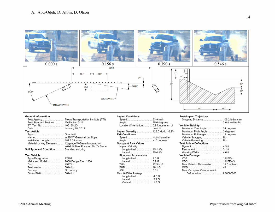
0.000 s 0.156 s 0.390 s 0.546 s
General Information Test Agency .............................. Test Standard Test No. ............. TTI Test No. ............................. Date ..........................................Test Article Type .......................................... Name ........................................ Installation Length ..................... Material or Key Elements .......... Soil Type and Condition ............ Test Vehicle Type/Designation ...................... Make and Model ....................... Curb .......................................... Test Inertial ............................... Dummy ..................................... Gross Static ..............................
Texas Transportation Institute (TTI) MASH test 3-11 405160-20-1 January 18, 2012 Guardrail WSDOT Guardrail on Slope 181 ft 3 inches 12 gauge W-Beam Mounted on W6x8.5 Steel Posts on 2H:1V Slope Standard soil, dry 2270P 2006 Dodge Ram 1500 4977 lb 5044 lb No dummy 5044 lb
Impact Conditions Speed.................................... Angle ..................................... Location/Orientation .............. Impact Severity .......................Exit Conditions Speed.................................... Angle .....................................Occupant Risk Values Impact Velocity Longitudinal ....................... Lateral ............................... Ridedown Accelerations Longitudinal ....................... Lateral ............................... THIV ...................................... PHD ...................................... ASI ........................................Max. 0.050-s Average Longitudinal ....................... Lateral ............................... Vertical ..............................
63.9 mi/h 25.0 degrees 0.9 ft upstream of post 14 123.0 kip-ft, >6.9% Not obtainable ~10 degrees 15.1 ft/s 15.4 ft/s 9.0 G 6.9 G 22.3 km/h 10.1 G 0.61 -4.5 G 5.1 G 1.8 G
Post-Impact Trajectory Stopping Distance .......................... Vehicle Stability Maximum Yaw Angle ..................... Maximum Pitch Angle .................... Maximum Roll Angle ...................... Vehicle Snagging ........................... Vehicle Pocketing ...........................Test Article Deflections Dynamic ......................................... Permanent ...................................... Working Width ................................Vehicle Damage VDS ................................................ CDC ............................................... Max. Exterior Deformation .............. OCDI .............................................. Max. Occupant Compartment Deformation .............................
106.2 ft dwnstrm 2.0 ft twd traffic 34 degrees 3 degrees 13 degrees No No 4.3 ft 3.1 ft 4.6 ft 11LFQ4 11LFEW3 11.0 inches nil LS0000000
Table 1: T
est 405160-20-1 Sum
mary S
heet
TRB 2013 Annual Meeting Paper revised from original submittal.
A. Abu-Odeh, D. Albin, D. Olson
15
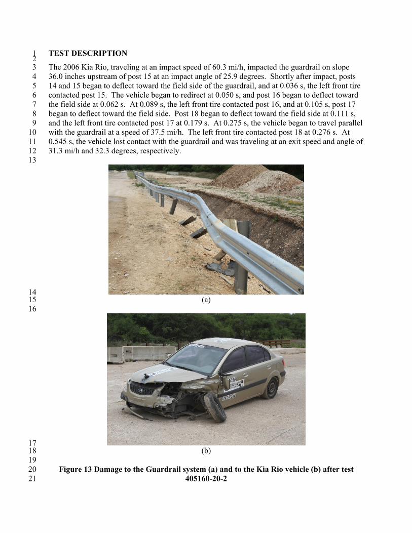
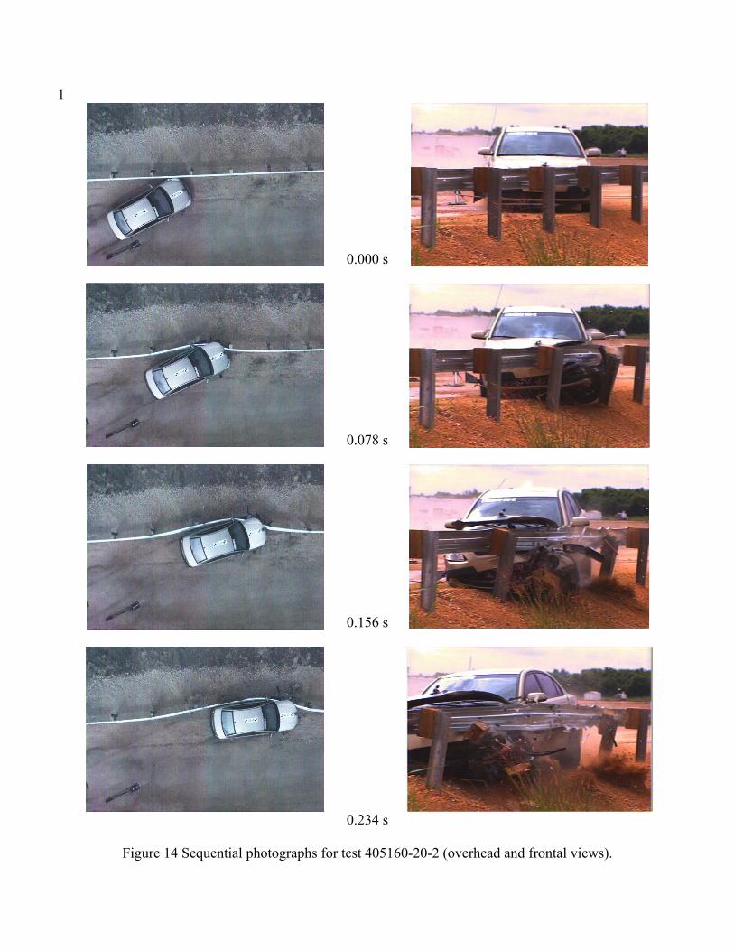
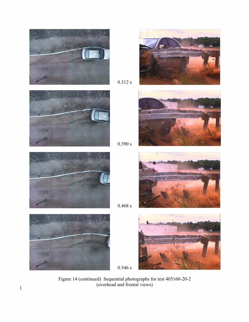
TEST DESCRIPTION 1 2 The 2006 Kia Rio, traveling at an impact speed of 60.3 mi/h, impacted the guardrail on slope 3 36.0 inches upstream of post 15 at an impact angle of 25.9 degrees. Shortly after impact, posts 4 14 and 15 began to deflect toward the field side of the guardrail, and at 0.036 s, the left front tire 5 contacted post 15. The vehicle began to redirect at 0.050 s, and post 16 began to deflect toward 6 the field side at 0.062 s. At 0.089 s, the left front tire contacted post 16, and at 0.105 s, post 17 7 began to deflect toward the field side. Post 18 began to deflect toward the field side at 0.111 s, 8 and the left front tire contacted post 17 at 0.179 s. At 0.275 s, the vehicle began to travel parallel 9 with the guardrail at a speed of 37.5 mi/h. The left front tire contacted post 18 at 0.276 s. At 10 0.545 s, the vehicle lost contact with the guardrail and was traveling at an exit speed and angle of 11 31.3 mi/h and 32.3 degrees, respectively. 12
13
14 (a) 15
16
17 (b) 18
19 Figure 13 Damage to the Guardrail system (a) and to the Kia Rio vehicle (b) after test 20
405160-20-2 21
TRB 2013 Annual Meeting Paper revised from original submittal.

A. Abu-Odeh, D. Albin, D. Olson
16
1 2
The damage to the vehicle and the guardrail system is shown in Figure 13 and sequential 3 photographs of the test period are shown in Figure 14 while test summary sheet is shown in 4 Table 2. 5
6 7
8
TRB 2013 Annual Meeting Paper revised from original submittal.
A. Abu-Odeh, D. Albin, D. Olson
17
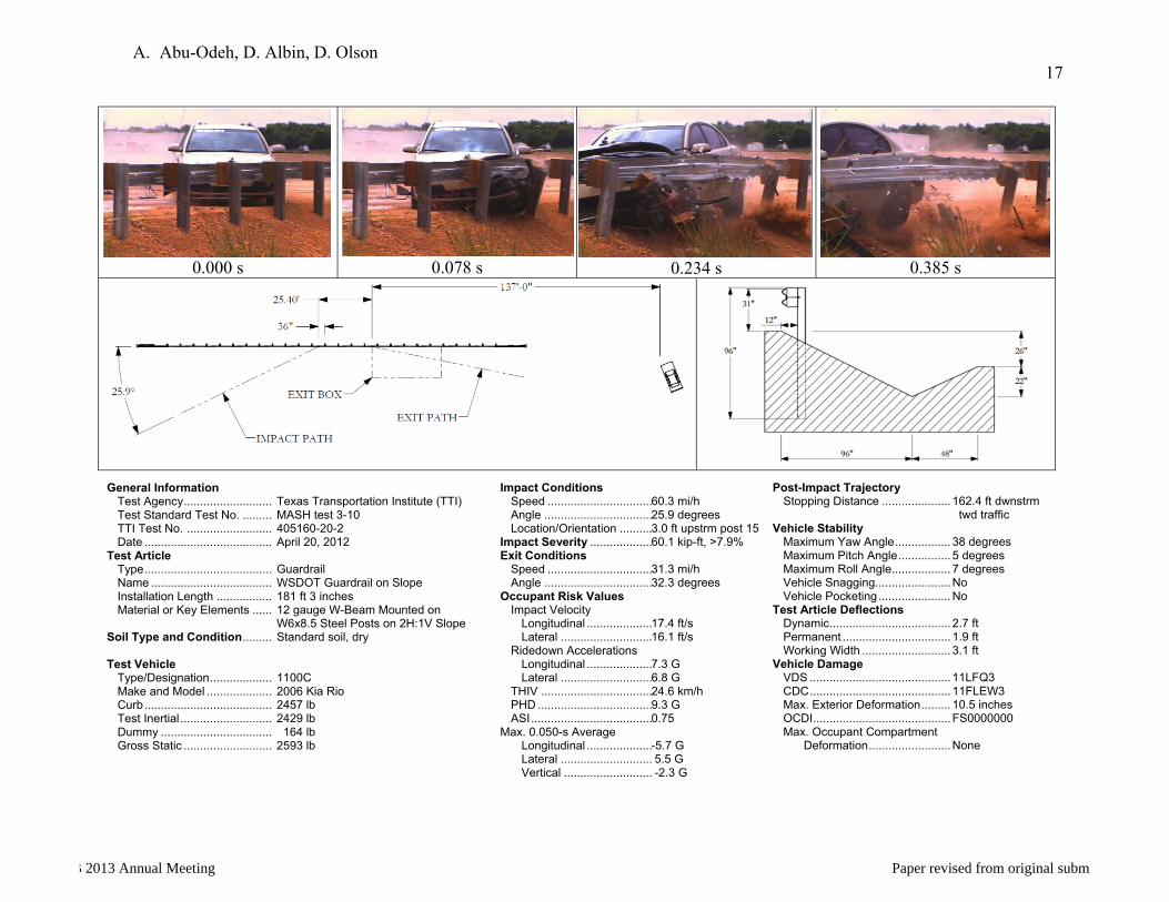
0.000 s 0.078 s 0.234 s 0.385 s
General Information Test Agency ........................... Test Standard Test No. ......... TTI Test No. .......................... Date .......................................Test Article Type ....................................... Name ..................................... Installation Length ................. Material or Key Elements ...... Soil Type and Condition ......... Test Vehicle Type/Designation ................... Make and Model .................... Curb ....................................... Test Inertial ............................ Dummy .................................. Gross Static ...........................
Texas Transportation Institute (TTI) MASH test 3-10 405160-20-2 April 20, 2012 Guardrail WSDOT Guardrail on Slope 181 ft 3 inches 12 gauge W-Beam Mounted on W6x8.5 Steel Posts on 2H:1V Slope Standard soil, dry 1100C 2006 Kia Rio 2457 lb 2429 lb 164 lb 2593 lb
Impact Conditions Speed ................................ Angle ................................. Location/Orientation ..........Impact Severity ...................Exit Conditions Speed ................................ Angle .................................Occupant Risk Values Impact Velocity Longitudinal .................... Lateral ............................ Ridedown Accelerations Longitudinal .................... Lateral ............................ THIV .................................. PHD ................................... ASI .....................................Max. 0.050-s Average Longitudinal .................... Lateral ............................ Vertical ...........................
60.3 mi/h 25.9 degrees 3.0 ft upstrm post 1560.1 kip-ft, >7.9% 31.3 mi/h 32.3 degrees 17.4 ft/s 16.1 ft/s 7.3 G 6.8 G 24.6 km/h 9.3 G 0.75 -5.7 G 5.5 G -2.3 G
Post-Impact Trajectory Stopping Distance ..................... Vehicle Stability Maximum Yaw Angle ................. Maximum Pitch Angle ................ Maximum Roll Angle .................. Vehicle Snagging....................... Vehicle Pocketing ......................Test Article Deflections Dynamic ..................................... Permanent ................................. Working Width ...........................Vehicle Damage VDS ........................................... CDC ........................................... Max. Exterior Deformation ......... OCDI .......................................... Max. Occupant Compartment Deformation .........................
162.4 ft dwnstrm twd traffic 38 degrees 5 degrees 7 degrees No No 2.7 ft 1.9 ft 3.1 ft 11LFQ3 11FLEW3 10.5 inches FS0000000 None
Table 2: T
est 405160-20-2 Sum
mary S
heet
TRB 2013 Annual Meeting Paper revised from original submittal.
A. Abu-Odeh, D. Albin, D. Olson
18
1
0.000 s
0.078 s
0.156 s
0.234 s
Figure 14 Sequential photographs for test 405160-20-2 (overhead and frontal views).
TRB 2013 Annual Meeting Paper revised from original submittal.
A. Abu-Odeh, D. Albin, D. Olson
19
0.312 s
0.390 s
0.468 s
0.546 s
Figure 14 (continued) Sequential photographs for test 405160-20-2 (overhead and frontal views)
1
TRB 2013 Annual Meeting Paper revised from original submittal.
A. Abu-Odeh, D. Albin, D. Olson
20
1
RESULTS AND CONCLUSIONS 2
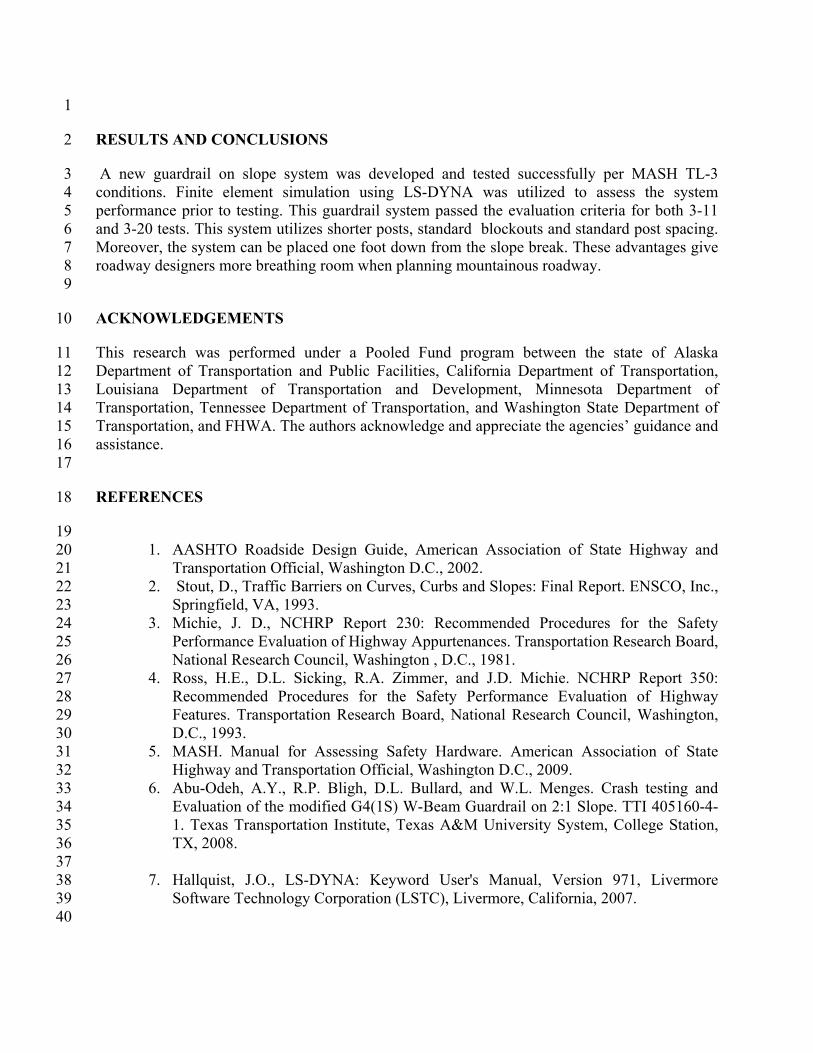
A new guardrail on slope system was developed and tested successfully per MASH TL-3 3 conditions. Finite element simulation using LS-DYNA was utilized to assess the system 4 performance prior to testing. This guardrail system passed the evaluation criteria for both 3-11 5 and 3-20 tests. This system utilizes shorter posts, standard blockouts and standard post spacing. 6 Moreover, the system can be placed one foot down from the slope break. These advantages give 7 roadway designers more breathing room when planning mountainous roadway. 8 9
ACKNOWLEDGEMENTS 10
This research was performed under a Pooled Fund program between the state of Alaska 11 Department of Transportation and Public Facilities, California Department of Transportation, 12 Louisiana Department of Transportation and Development, Minnesota Department of 13 Transportation, Tennessee Department of Transportation, and Washington State Department of 14 Transportation, and FHWA. The authors acknowledge and appreciate the agencies’ guidance and 15 assistance. 16
17
REFERENCES 18
19 1. AASHTO Roadside Design Guide, American Association of State Highway and 20
Transportation Official, Washington D.C., 2002. 21 2. Stout, D., Traffic Barriers on Curves, Curbs and Slopes: Final Report. ENSCO, Inc., 22
Springfield, VA, 1993. 23 3. Michie, J. D., NCHRP Report 230: Recommended Procedures for the Safety 24
Performance Evaluation of Highway Appurtenances. Transportation Research Board, 25 National Research Council, Washington , D.C., 1981. 26
4. Ross, H.E., D.L. Sicking, R.A. Zimmer, and J.D. Michie. NCHRP Report 350: 27 Recommended Procedures for the Safety Performance Evaluation of Highway 28 Features. Transportation Research Board, National Research Council, Washington, 29 D.C., 1993. 30
5. MASH. Manual for Assessing Safety Hardware. American Association of State 31 Highway and Transportation Official, Washington D.C., 2009. 32
6. Abu-Odeh, A.Y., R.P. Bligh, D.L. Bullard, and W.L. Menges. Crash testing and 33 Evaluation of the modified G4(1S) W-Beam Guardrail on 2:1 Slope. TTI 405160-4-34 1. Texas Transportation Institute, Texas A&M University System, College Station, 35 TX, 2008. 36
37 7. Hallquist, J.O., LS-DYNA: Keyword User's Manual, Version 971, Livermore 38
Software Technology Corporation (LSTC), Livermore, California, 2007. 39 40
TRB 2013 Annual Meeting Paper revised from original submittal.
A. Abu-Odeh, D. Albin, D. Olson
21
8. National Crash Analysis Center. NCAC Finite Element Model Archive. 1 http://www.ncac.gwu.edu/vml/models.html. Accessed: Dec 10, 2008 2
3 9. Polivka, K.A., Faller, R.K., Sicking, D.L., Rohde, J.R., Holloway, J.C., and Keller, 4
E.A., Development of a W-Beam Guardrail System for Use on a 2:1 Slope, Final 5 Report to the Midwest State=s Regional Pooled Fund Program, Transportation 6 Research Report No. TRP-03-99-00, Project No. SPR-3(017)-Years 9 & 10, 7 Midwest Roadside Safety Facility, University of Nebraska-Lincoln, October 16, 8 2000. 9
10 10. Wiebelhaus, M.J., Lechtenberg, K.A., Faller, R.K., Sicking, D.L., Bielenberg, R.W., 11
Reid, J.D., Rohde, J.R., and Dey, Gopi, Development and Evaluation of the 12 Midwest Guardrail System (MGS) Placed Adjacent to a 2:1 Fill Slope, Final Report 13 to the Midwest State’s Regional Pooled Fund Program, Transportation Research 14 Report No. TRP-03-185-10, Project No.: SPR-3(017), Project Code: RPFP-05-09 - 15 Year 15, Midwest Roadside Safety Facility, University of Nebraska-Lincoln, 16 Lincoln, Nebraska, February 24, 2010. 17
18
TRB 2013 Annual Meeting Paper revised from original submittal.