Embed Size (px)
Citation preview
1083-4435 (c) 2019 IEEE. Personal use is permitted, but republication/redistribution requires IEEE permission. See http://www.ieee.org/publications_standards/publications/rights/index.html for more information.
This article has been accepted for publication in a future issue of this journal, but has not been fully edited. Content may change prior to final publication. Citation information: DOI 10.1109/TMECH.2019.2953598, IEEE/ASMETransactions on Mechatronics
> REPLACE THIS LINE WITH YOUR PAPER IDENTIFICATION NUMBER (DOUBLE-CLICK HERE TO EDIT) <
1
Abstract—This paper presents a new lizard-inspired robot that
can maintain its direction of movement via S-shaped lateral body
motions during its high-speed bipedal running. For this purpose,
a dynamic model and a control scheme for the proposed robot
were derived to simulate the S-shaped lateral body motions of a
real lizard. Based on simulations using the dynamic model with the
proposed control scheme, a prototype of lizard-inspired robot was
built to reproduce a bipedal running gait as well as the lateral body
motions of a real lizard. The simple robot body consisted of three
links connected by two rotational joints and its hind legs were
optimally designed upon a 4-bar linkage combined with an ankle
mechanism. The experimental tests using the proposed robot were
performed by confining its motion in the horizontal plane, which
demonstrated that the proposed robot can successfully maintain
its direction of movement via the S-shaped lateral motion adjusted
by the yaw angle of its posterior body during its bipedal running
gait similar to the gait of a real lizard.
Index Terms— 4-bar linkage, bipedal running gait, lizard-
inspired robot, S-shaped lateral body motion
I. INTRODUCTION
EGGED animals have naturally evolved to attain the ability
to overcome various types of obstacles encountered in their
surrounding environments. Therefore, for a long time, many
investigations have been carried out to focus on developing
legged and wheel-legged robots to traverse rough terrains stably
by mimicking the locomotive mechanisms of legged animals
with excellent obstacle-climbing abilities [1]-[7].
Because some legged robots are fully or redundantly actuated,
their poses, directions of movement, and moving speeds can be
controlled simultaneously and rapidly and as a result, they have
excellent locomotive capabilities. For example, humanoids can
walk on rough terrains naturally using two feet like humans [8]-
[10]. Furthermore, the MIT Cheetah can jump over obstacles up
to 40 cm in height at the running speed of 2.4 m/s [11] and the
cheetah developed by Boston Dynamics is reported to run at a
speed of 12.6 m/s. In general, these fully or redundantly
This work was supported by Basic Science Research Program through the
National Research Foundation of Korea grants funded by the Ministry of Education (NRF-2016R1D1A1B03935516 and NRF-2019R1A2C1008163)
and by the GRRC program of Gyeonggi province [GRRC2019-B02, Research
on Innovative Intelligent Manufacturing System]. (Co-corresponding authors: TaeWon Seo and Hwa Soo Kim)
J. Kim, H. Kim, Y. Kim, and J. Kim are with School of Mechanical and Aerospace Engineering, Seoul National University, 1 Gwanak-ro, Gwanak-gu, Seoul 08826, South Korea (e-mails: {jrkim, hmkim, yskim}
@rodel.snu.ac.kr, [email protected]).
actuated legged robots are large, heavy and complicated due to
their many actuators and sensors.
On the contrary, some legged robots are under-actuated, but
they can achieve performances comparable to those of fully or
redundantly actuated ones without implementing all the degrees
of freedom required to mimic the locomotive mechanisms of
legged animals. For example, iSprawl is the six-legged robot
inspired by a cockroach that can run at a speed of 2.3 m/s by
converting the rotational motions from two motors into periodic
thrusting motions. Also, flexible push/pull cables are adopted
to rapidly swing six legs [12]. Similarly, VelociRoACH is the
six-legged robot that can run at a speed of 2.7 m/s by combining
two motors with a lightweight linkage mechanism. Moreover,
it has the ability to steer its direction of movement easily by
using an aerodynamic stabilizer [13], [14]. It is noteworthy that
iSprawl and VelociRoACH are hexapedal runner so that more
than three legs always have good contact with the ground so
that their locomotion is always stable. Since their body consists
of one rigid section, their directions of movements are mainly
controlled by their leg motions.
Typically, an under-actuated bipedal robot cannot maintain
its posture as well as its direction of movement simultaneously
during bipedal running due to the inherent lack of degrees of
freedom (DOFs) of its motion. A possible solution to such lack
of DOFs caused by under-actuation may be additional motions
of the body. The investigations have been carried out on legged
robots that can keep their postures stable by utilizing some parts
of their bodies besides their legs or wheels. For example, an
active tail has been widely used due to its structural simplicity:
the motion stability of six-legged water-running robot in the
yaw- and pitch-direction is improved by using a 2 DOF active
tail [15]. The six-legged robot TAYLRoACH with a 1 DOF
active tail can make sudden 90° turns at a constant rotational
speed of 360°/s in the horizontal plane [16]. Also, the lizard-
sized wheeled robot Tailbot can keep its pitch angle constant
via the swing of its 1 DOF active tail in a manner to redirect the
angular momentum from its body to its tail [17]. Similarly, the
J. Park is with the Department of Transdisciplinary Studies, Seoul National
University, 1 Gwanak-ro, Gwanak-gu, Seoul 08826, South Korea (e-mail: [email protected])
T. Seo is with the School of Mechanical Engineering, Hanyang University, Seoul 04763, Republic of Korea (e-mail: [email protected])
H. S. Kim is with the Department of Mechanical System Engineering,
Kyonggi University, Suwon, Gyeonggi-do 16227, South Korea (e-mail: [email protected]).
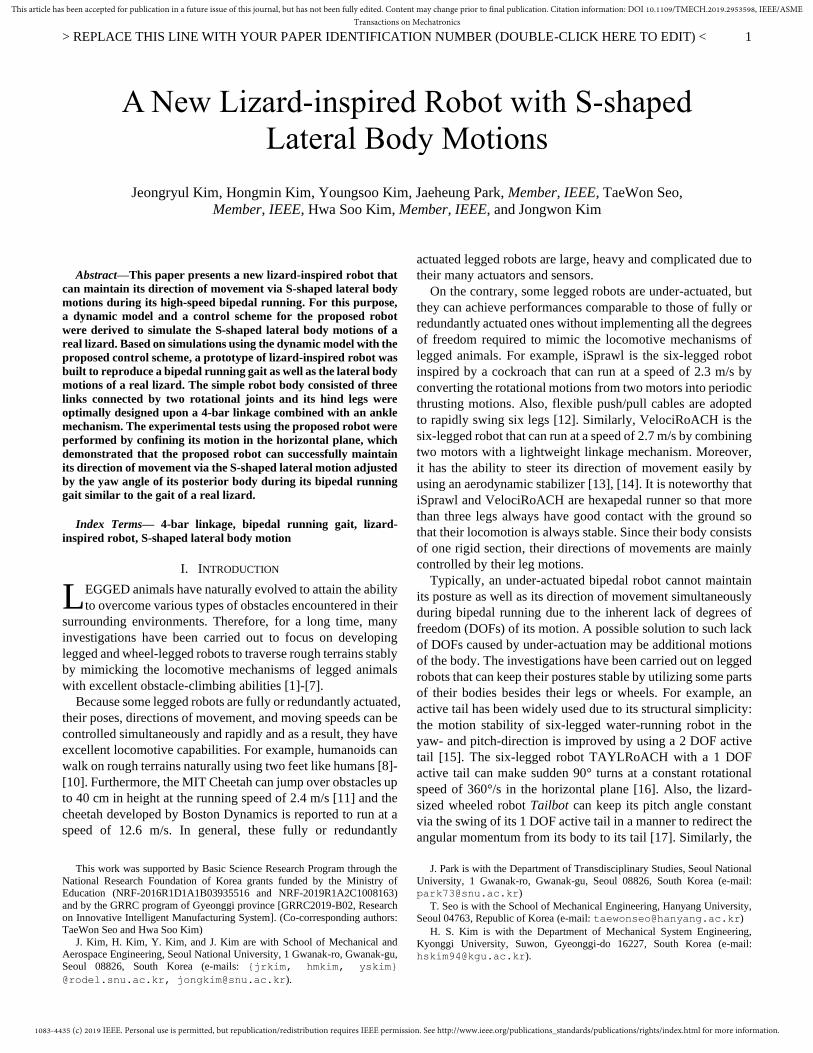
A New Lizard-inspired Robot with S-shaped
Lateral Body Motions
Jeongryul Kim, Hongmin Kim, Youngsoo Kim, Jaeheung Park, Member, IEEE, TaeWon Seo,
Member, IEEE, Hwa Soo Kim, Member, IEEE, and Jongwon Kim
L

1083-4435 (c) 2019 IEEE. Personal use is permitted, but republication/redistribution requires IEEE permission. See http://www.ieee.org/publications_standards/publications/rights/index.html for more information.
This article has been accepted for publication in a future issue of this journal, but has not been fully edited. Content may change prior to final publication. Citation information: DOI 10.1109/TMECH.2019.2953598, IEEE/ASMETransactions on Mechatronics
> REPLACE THIS LINE WITH YOUR PAPER IDENTIFICATION NUMBER (DOUBLE-CLICK HERE TO EDIT) <
2
bipedal robot MSU Tailbot can maneuver in midair for safe
landings by utilizing a 1-DOF active tail [18]. It is noted that
TAYLRoACH, Tailbot and MSU tailbot can control their poses
stably by using the active pendulum unlike iSprawl without a
tail or VelociRoACH with a fixed tail. The design, scaling and
control of active tails for planar aerial reorientation is detailedly
discussed in [31].
Recently, many investigations of lizard behavior have been
carried out due to their excellent mobility and stability on rough
terrains. For example, the effect of periodical lateral motion of
a real lizard during running is studied in [20], [21]. Moreover,
the relation between the pace angulation and the pelvic rotation
is uncovered [22] and also, to reveal the role of muscles in real
lizards, the investigations using the electromyography (EMG)
have been carried out [23]-[25]. Based on these observations,
some research has verified the principle of body motion of a
real lizard via lizard-inspired robotic platforms. For example, it
is shown that the tail of a lizard plays an important role in
keeping its motion stable [15], [17] or the flexibility of lizard
body is strongly related with the efficiency of its crawling gait
[26]. However, since their locomotion is based on multiple legs
or wheels, their motions have nothing to do with the bipedal
running of a lizard. On the other hand, Salamander Robotica is
known for the similarity of its gait controlled by the central
pattern generator (CPG) to that of a real salamander [19], [32].
It can control the periodic yaw angle of its body by changing
the curvature of body consisting of eight flexible spines. Since
the gait of Salamander Robotica is based on a quadruped gait,
its duty factor (defined as the ratio of contact time of one leg
over one gait cycle using both legs) is larger than that of bipedal
running gait of lizard so that its walking on the ground is quite
stable but relatively slow. So far as is known, the effect of S-
shaped lateral bending of body along the yaw direction during
bipedal running has not been studied in previous investigations
on bio-inspired robots comprehensively.
The final goal of our study is to develop a perfect bipedal
running robot that can keep its direction of movement via the
S-shaped lateral body motions similar to those of real lizard
Callisaurus draconoides. In this work, as a stepping stone to a
perfect bipedal running robot, we have focused on verifying
that the direction of movement of a bipedal running robot can
be managed by adjusting its body motion in the 2-D horizontal
plane. To this end, we have first derived a 2-D dynamic model
of a prototype of bipedal running robot to generate a bipedal
running gait without slip as well as a S-shaped body motion
adjusted by the error between the yaw angle of body and the
direction of movement. Second, for the experimental validation,
we have constructed a prototype of bipedal running robot
consisting of three links, whose hind legs are optimally
designed upon a 4-bar linkage to reproduce the tip trajectory
very similar to that of C. draconoides. Also, for sufficient
friction, the ankle linkage is added to the leg to ensure the
constant contact angle between the tip and a ground. Third, we
have adopted the high- and low-level PD controllers in series
driven by the yaw error of robot body in order to achieve a S-
shaped motion of the prototype of bipedal running robot and we
have experimentally verified that it can keep its direction of
movement during its bipedal running. It is noteworthy that in
order to consider only the effect of lateral body motion of the
prototype of robot on the direction of movement, the effect of
balancing by its hind legs is minimized by confining the motion
of prototype of robot within the 2-D horizontal plane. However,
different from previous investigations inspired by lizards, this
work is the only case to handle the direction of movement of
the bipedal running robot by swinging its body properly in the
horizontal plane without the force control of its legs, i.e., its legs
just run for locomotion. In summary, dynamic modeling, design
of the prototype robot and two-level feedback control scheme
have been successfully incorporated to verify the effect of
lateral body undulation on the direction of movement.
The rest of paper is organized as follows: Section II presents
a dynamic model of the lizard-inspired robot and a control
framework for gait planning of the proposed robot. The design
of prototype of the new lizard-inspired robot is in details shown
in Section III. In order to investigate the ability of the proposed
robot to maintain its direction of movement even during bipedal
running gait, the experiments using the prototype of robot are
carried out on a treadmill to constrain its motions in the 2-D
horizontal plane, and the results are discussed in Section IV.
II. DYNAMIC MODELING OF A LIZARD-INSPIRED ROBOT
A. Dynamic Modeling
It is noteworthy that the main goal of this study was to build
a lizard-inspired robot that could maintain its direction of
movement by mimicking the S-shaped lateral motions of C.
draconoides. To this end, some attributes of dynamic model of
the lizard-inspired robot were simplified to focus on the goal.
First, the degree-of-freedom (DOF) of the dynamic model is
assumed to be three so that the possible motions of proposed
robot would be two translations on the XY plane and rotation
along the Z-axis, as shown in Fig. 1. Next, the dynamic model
is assumed to move at a constant speed during its bipedal
running gait (similar to C. draconoides). Third, the time periods
for the motions of body, tail and hind legs are assumed to be
constant. Finally, the leg motion of the dynamic model is
controlled by the open-loop control so that its legs repeated the
same motion in every period and touched the ground. It is
Fig. 1. Schematics of (a) symbols and (b) coordinate frames and joint variables
for the lizard-inspired robot.

1083-4435 (c) 2019 IEEE. Personal use is permitted, but republication/redistribution requires IEEE permission. See http://www.ieee.org/publications_standards/publications/rights/index.html for more information.
This article has been accepted for publication in a future issue of this journal, but has not been fully edited. Content may change prior to final publication. Citation information: DOI 10.1109/TMECH.2019.2953598, IEEE/ASMETransactions on Mechatronics
> REPLACE THIS LINE WITH YOUR PAPER IDENTIFICATION NUMBER (DOUBLE-CLICK HERE TO EDIT) <
3
noteworthy that unlike a snake whose sideways motion slipping
on the ground plays an essential role in forward propulsion, the
lateral body motion of the proposed robot had little effect on its
forward propulsion because there is a negligible slip between
its body and the ground.
Fig. 1(a) shows the schematics of coordinate frames and joint
variables for the proposed robot, where y is the yaw angle of
the posterior body section, and s
l and b
d are the stroke of the
tip of the hind leg and the distance from the posterior body
section to the hind leg. i
l and i
w are the length and the width
of the anterior and posterior body sections and tail ( i = 1, 2, 3),
with values from the length and width of C. draconoides, as
shown in Table I [20]. Because the weight of the front leg of C.
draconoides is just 2% of its weight, the front legs is neglected
in the dynamic modeling, but the hind legs are regarded as slide
joints. This is because, while the hind leg of C. draconoides
stays in contact with the ground, its tip trajectory moving from
front to back can be approximated by a linear reciprocating
motion on the XY plane [27], [28].
To express the position and yaw angle of the dynamic model
in the XY plane, three virtual variables (1q ,
2q , and 3q ) are
used as shown in Fig. 1(b). While 4q and
5q are the angles of
the waist and tail joints, 6q and
7q are the displacements of the
slide joints, respectively. With 1 7[ ]Tq q q= , the equation of
motion is derived as
( , )( ) T
c cA q b q q Jq f+ + = (1)
where 7 7( )A q R and 7 1)( ,b q q R are the joint space inertia
matrix and the Coriolis and centrifugal force vector. 3 7
cJ R ,
3 1
cf R , and 7 1R are the Jacobian matrix, the reaction
force and moment vector and the torque vector, respectively.
The Jacobian matrix cJ is defined as
c cx J q= with the contact
vector 3 1
cx R in Fig. 1(b). By replacing q with
1( )c c c
q J x J q−= − , (1) becomes
1 1( , )( )
Tcc
c c c c c c c c
J
J A q fx b q q J J Aq
− − =+ − + (2)
where c and
c denote the inertia matrix and the Coriolis
and centrifugal force vector at contact point, and cJ is the
dynamically consistent inverse matrix of cJ [29]. In this study,
to ensure no slip of foot at the contact point, the acceleration of
the foot is supposed to satisfy the following constraint [30]:
22 0c c cx x x + + = (3)
where and are the positive Baumgarte parameters. By
combining (3) with (2), the reaction force and moment vector
cf can be obtained as
2( 2 )T
c c c c c cf J x x = − − − − (4)
Substituting (4) into (1) derives the forward dynamics of the
proposed robot in the contact condition as
1 2( ) ( ), () 2T
c c c c cxq A q b q q J x − − − − −= −− (5)
In the non-contact condition (3 1cf = 0 ), the forward dynamics
is given by
1( ) ( , )q A q b q q− −= (6)
More information about the parameters and forward kinematics
of the proposed robot are given in details in the Appendix.
B. Locomotion Simulation
It is noted that the aim of dynamic modeling was to simulate
a stable bipedal running gait for the proposed lizard-inspired
robot to maintain its direction of movement via proper angular
movement of waist and tail. In this study, the direction of
movement of the robot is defined as the median value of the
yaw angle of its posterior body section. Note that even when a
lizard runs straight, the yaw angle of its posterior body section
may change continuously but its median value remains constant
toward its direction of movement.
In this study, the duty factor chosen for the bipedal running
gait of the dynamic model is set to be 0.25 (similar to that of C.
draconoides) so that the duration that one leg is in touch with
the ground is equal to the duration that both legs are in the air,
as shown in Fig. 2(a). For a S-shaped body motion, the dynamic
model is supposed to move like a sinusoidal wave so that the
directions of the anterior body section and tail were exactly the
same, but opposite to that of the posterior body section, as
shown in Fig. 2(b). For the simplicity of simulation, the rotating
angle of the tail is equal to that of the anterior body section.
The basic principle of maintaining the direction of movement
via angular motions of the dynamic model is based upon the
conservation of angular momentum. The dynamic model may
be placed in two situations: either one foot is in contact with the
ground or all feet are in the air. When one foot is in contact with
the ground, the direction of movement of the dynamic remains
constant due to friction for any angular motions of the anterior
body section and tail, as shown in phases [I] and [III] of Fig.
2(b). In contrast, when all feet are in the air, the yaw angle of
posterior body section rotates in the opposite direction to the
rotating angles of waist and tail joints by the principle of
conservation of angular momentum, as shown in phases [II] and
[IV] of Fig. 2(b). Thus, during time period T , the direction of
movement of dynamic model is changed by the difference
between counter-clockwise and clockwise rotating angles 4
ccwq
and 4
cwq in Fig. 2(b), where the direction of movement of the
dynamic model is denoted by the black dotted arrow.
TABLE I
SPECIFICATIONS OF DYNAMIC MODEL OF LIZARD-INSPIRED ROBOT
Length Width Weight Inertia
Anterior link 182 mm 55 mm 0.89 kg 0.0026 kg m2
Posterior link 115 mm 55 mm 1.46 kg 0.0019 kg m2
Tail link 231 mm 20 mm 0.19 kg 0.0008 kg m2
Foot 30 mm 30 mm 0.18 kg 0.000027 kg m2
TABLE I
SPECIFICATIONS OF DYNAMIC MODEL OF LIZARD-INSPIRED ROBOT
Length Width Weight Inertia
Anterior link 182 mm 55 mm 0.89 kg 0.0026 kg m2
Posterior link 115 mm 55 mm 1.46 kg 0.0019 kg m2
Tail link 231 mm 20 mm 0.19 kg 0.0008 kg m2
Foot 30 mm 30 mm 0.18 kg 0.000027 kg m2

1083-4435 (c) 2019 IEEE. Personal use is permitted, but republication/redistribution requires IEEE permission. See http://www.ieee.org/publications_standards/publications/rights/index.html for more information.
This article has been accepted for publication in a future issue of this journal, but has not been fully edited. Content may change prior to final publication. Citation information: DOI 10.1109/TMECH.2019.2953598, IEEE/ASMETransactions on Mechatronics
> REPLACE THIS LINE WITH YOUR PAPER IDENTIFICATION NUMBER (DOUBLE-CLICK HERE TO EDIT) <
4
It is noteworthy that for the TAYLRoACH to change its
direction of movement, it swings its tail in the desired direction
of movement all at one time. However, because its tail is as
heavy as its main body, it is likely to suffer from slip of its feet
and as a result, its center of mass (CoM) may be shifted, or its
capability to change its direction of movement may be degraded
by the limited rotating angle [16]. In contrast, the principle of
motion used for the dynamic model allows the waist and tail to
come back to their original positions, as shown in phases [II]
and [IV] of Fig. 2(b). This enables the dynamic model to rotate
over a sufficiently large angle with a relatively stable CoM
during a bipedal running gait.
Fig. 3 shows a block diagram of the control scheme for the
locomotion simulation. The yaw angle error e is defined by
the difference between the desired moving angle d and the
real yaw angle of the posterior body section re . From this yaw
angle error e , the desired waist and tail joint angles 4,dq and
5,dq are calculated by (7):
( )4,
5, 4,
)s
)
( ) 2(
( )
in /
(
y y
p
d
dd
d
q t k k e t
q q
Te
t t
= +
=
− (7)
where y
pk and y
dk denote the positive control gains of high-
level PD controller. It is noted that, because the magnitudes of
waist and tail joints angles are the same, but their signs are
opposite, the S-shaped lateral motion of the dynamic model can
be efficiently implemented. Recall that during the locomotion
simulation, the desired slide joints 6,dq and 7,dq for the hind
legs are computed by (7) irrespective of the yaw angle error:
4
2 4
4 5
3 6 4
6,
7, 6, 2
if 0( )
if
( ) ( )
s
s
s
sl l T
T
l ld
d
T
T
d
t tq t
t t T
q t q t
− =
− +
= +
(8)
where T and sl are the time period of one gait cycle and the
stroke of the tip of the hind leg when it remains in contact with
the ground, respectively. Note that the motions of the left and
right hind legs have the time difference of 0.5T and that,
according to the motion in (8), the speed to move the hind leg
from back to front is three times slower than the speed to move
the hind leg from front to back. Also, note that the real yaw
angle of the posterior body section is checked every half period
of 0.5T s when the whole body is straight, for example, it is
checked at the times 2t and
4t in Fig. 2(b). Based on the joint
error iqe between the desired and real joint angle
,i dq and ,i req ,
the required torque i , i = 1, , 7 is generated by:
, , (( ) , )( )i ii q
t t
i p q i dA q k e k e b q q ++ = (9)
where ,
t
i pk and ,
t
i dk are the positive control gains of low-level
PD controller. Note that i = 0 holds because
iq , i = 1, 2, 3 is
the virtual joint variable used to express the position and the
orientation of the dynamic model. Therefore, If the foot of
dynamic model stays in contact with the ground, the 2nd order
derivative of real joint variable ,i req of dynamic model is
obtained from (5) by using cf and
i given by (5) and (9),
respectively. Otherwise, ,i req is obtained by (6) with
3 1cf = 0
and i given by (9). Then, the real joint variable ,i req can be
calculated by using the 4th order Runge-Kutta method. The
positive gains of high- and low-level PD controllers for the
dynamic model are chosen by the trial and error method to
ensure the stable motion of the dynamic model.
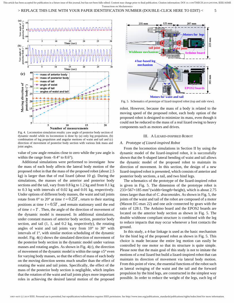
Fig. 4 shows the locomotion simulation results of the yaw
angle of the posterior body section of the dynamic model, where
the desired moving angle is set to zero and denoted by the red
dotted line. While Fig. 4(a) corresponds to the case that the
locomotion of the dynamic model was done by open-loop leg
propulsion without angular motions of waist and tail, Fig. 4(b)
corresponds to the case that the locomotion was done by open-
loop leg propulsion with angular motions of the waist and tail
according to the control framework in Fig. 3. Because the mean
value of the yaw angle of the posterior body section in Fig. 4(a)
increases gradually with respect to the reference line, the
resulting direction of movement of the posterior body section
of dynamic model will eventually be upward. In contrast, the
direction of movement of the dynamic model in Fig. 4(b) is kept
relatively constant with the help of periodic S-shaped lateral
motions of waist and tail computed by (7) and (8) (i.e., the mean
Fig. 3. Block diagram of control framework for locomotion simulation of
proposed dynamic model.
Fig. 2. (a) Motion plan of left and right hind legs of dynamic model with duty
ratio of 0.25 during a time period and (b) corresponding phases of change in its direction of movement via conservation of angular momentum.
1083-4435 (c) 2019 IEEE. Personal use is permitted, but republication/redistribution requires IEEE permission. See http://www.ieee.org/publications_standards/publications/rights/index.html for more information.
This article has been accepted for publication in a future issue of this journal, but has not been fully edited. Content may change prior to final publication. Citation information: DOI 10.1109/TMECH.2019.2953598, IEEE/ASMETransactions on Mechatronics
> REPLACE THIS LINE WITH YOUR PAPER IDENTIFICATION NUMBER (DOUBLE-CLICK HERE TO EDIT) <
5
value of yaw angle remains close to zero while the yaw angle is
within the range from -9.4° to 8.6°).
Additional simulations were performed to investigate how
the mass of each body affects the lateral body motion of the
proposed robot in that the mass of the proposed robot (about 2.5
kg) is larger than that of real lizard (about 10 g). During the
simulations, the masses of the anterior and posterior body
sections and the tail, vary from 0.8 kg to 1.2 kg and from 0.1 kg
to 0.3 kg with intervals of 0.02 kg and 0.01 kg, respectively.
Under options of different body masses, the waist and tail joints
rotate from 0° to 20° at time 0.25t T= , return to their starting
positions at time 0.5t T= , and remain stationary until the end
of time t T= . Then, the angle of the direction of movement of
the dynamic model is measured. In additional simulations,
under constant masses of anterior body section, posterior body
section, and tail (1, 1, and 0.2 kg, respectively), the rotating
angles of waist and tail joints vary from 10° to 30° with
intervals of 1°, with similar motion scheduling of the dynamic
model. Fig. 4(c) shows the simulated direction of movement of
the posterior body section in the dynamic model under various
masses and rotating angles. As shown in Fig. 4(c), the direction
of movement of the dynamic model is within the range ±5° even
for varying body masses, so that the effect of mass of each body
on the moving direction seems much smaller than the effect of
rotating the waist and tail joints. Specifically, the effect of the
mass of the posterior body section is negligible, which implies
that the rotation of the waist and tail joints plays more important
roles in achieving the desired lateral motion of the proposed
robot. However, because the mass of a body is related to the
moving speed of the proposed robot, each body option of the
proposed robot is designed to minimize its mass, even though it
could not be reduced to the mass of a real lizard owing to heavy
components such as motors and drives.
III. A LIZARD-INSPIRED ROBOT
A. Prototype of Lizard-inspired Robot
From the locomotion simulations in Section II by using the
dynamic model of the lizard-inspired robot, it is successfully
shown that the S-shaped lateral bending of waist and tail allows
the dynamic model of the proposed robot to maintain its
direction of movement. In this section, the design of a new
lizard-inspired robot is presented, which consists of anterior and
posterior body sections, a tail, and two hind legs.
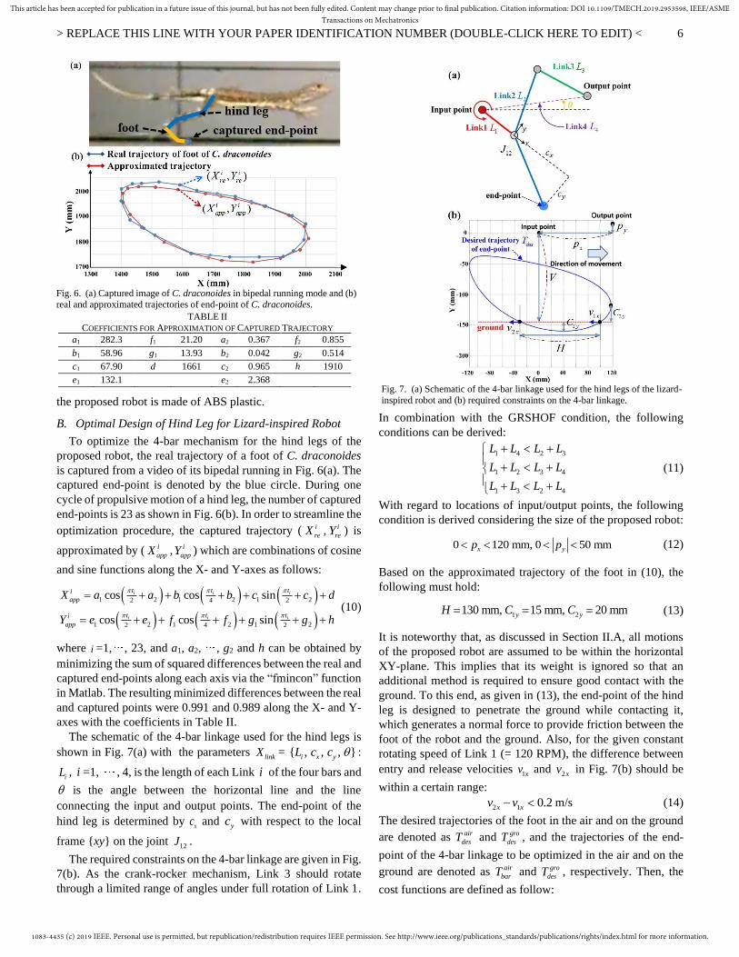
The schematics of the prototype of the lizard-inspired robot
is given in Fig. 5. The dimension of the prototype robot is
233×567×185 mm3 (width×length×height), which is about 2.75
times larger than that of C. draconoides. As shown in Fig. 5, the
joints of the waist and tail of the robot are composed of a motor
(Maxon EC-max 22) and one axle connected by gears with the
ratio of 128:1. The Arduino board and the EPOS2 boards are
located on the anterior body section as shown in Fig. 5. The
double wishbone compliant structure is combined with the leg
to reduce impacts that may occur whenever a foot contacts the
ground.
In this study, a 4-bar linkage is used as the basic mechanism
for the hind leg of the proposed robot as shown in Fig. 5. This
choice is made because the entire leg motion can easily be
controlled by one motor so that its structure is quite simple.
Please note that the main goal of this study is not to imitate the
motions of a real lizard but build a lizard-inspired robot that can
maintain its direction of movement via lateral body motion.
From this point of view, the essential functions of the robot such
as lateral swinging of the waist and the tail and the forward
propulsion by the hind legs, are constructed in the simplest way
possible. In order to reduce the weight of the legs, each leg of
tail joint
28 mm207 mm
125 mm
235 mm
waist joint
waist jointtail joint
125 mm
Arduino board
22
3 m
m
Motors for legs
18
5 m
m
EPOS2 boards
4 bar-based leg
mechanism
207 mm235 mm
Wishbone mechanism
Motors for waist and tail
Fig. 5. Schematics of prototype of lizard-inspired robot (top and side view).
Fig. 4. Locomotion simulation results: yaw angle of posterior body section of dynamic model while its locomotion is done by (a) only leg propulsion, (b)
combination of leg propulsion and angular motions of waist and tail and (c)
direction of movement of posterior body section with various link mass and joint angles.
1083-4435 (c) 2019 IEEE. Personal use is permitted, but republication/redistribution requires IEEE permission. See http://www.ieee.org/publications_standards/publications/rights/index.html for more information.
This article has been accepted for publication in a future issue of this journal, but has not been fully edited. Content may change prior to final publication. Citation information: DOI 10.1109/TMECH.2019.2953598, IEEE/ASMETransactions on Mechatronics
> REPLACE THIS LINE WITH YOUR PAPER IDENTIFICATION NUMBER (DOUBLE-CLICK HERE TO EDIT) <
6
the proposed robot is made of ABS plastic.
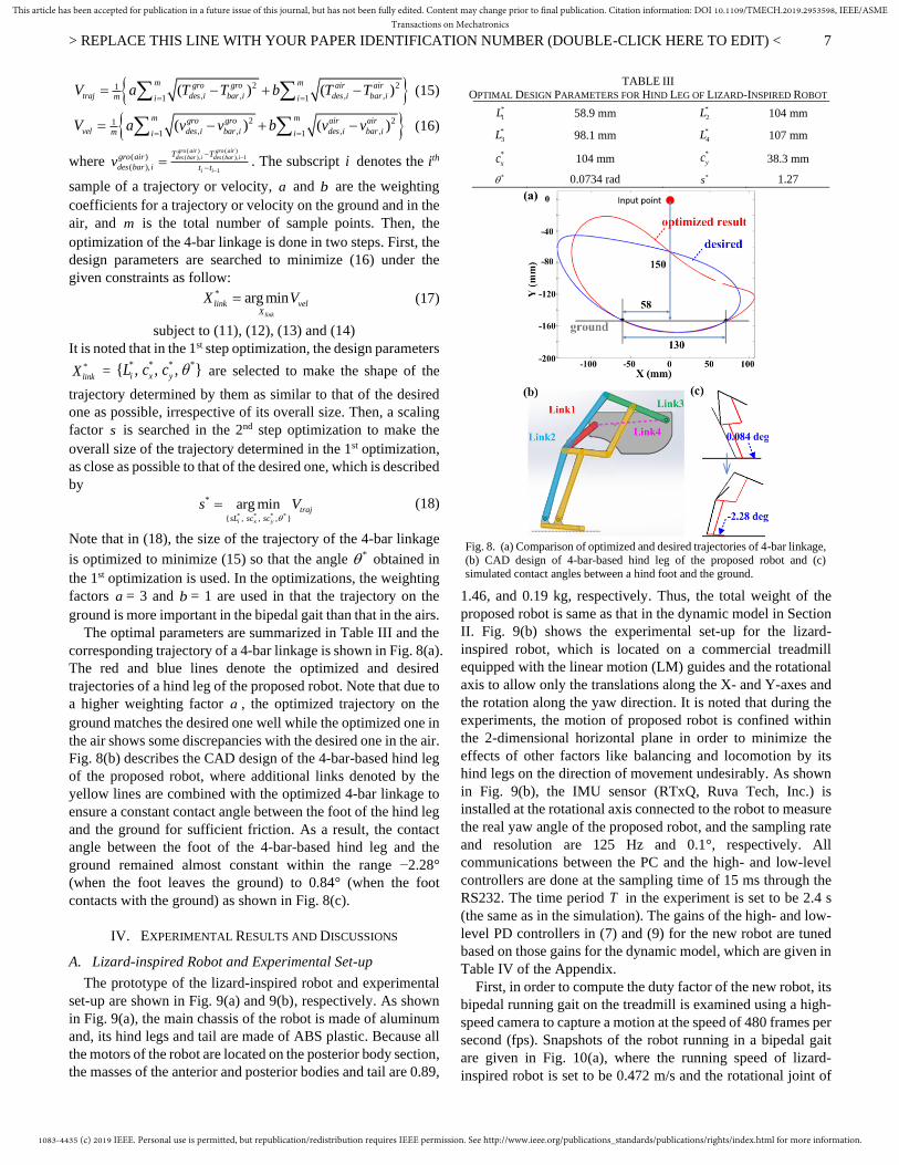
B. Optimal Design of Hind Leg for Lizard-inspired Robot
To optimize the 4-bar mechanism for the hind legs of the
proposed robot, the real trajectory of a foot of C. draconoides
is captured from a video of its bipedal running in Fig. 6(a). The
captured end-point is denoted by the blue circle. During one
cycle of propulsive motion of a hind leg, the number of captured
end-points is 23 as shown in Fig. 6(b). In order to streamline the
optimization procedure, the captured trajectory ( i
reX , i
reY ) is
approximated by ( i
appX , i
appY ) which are combinations of cosine
and sine functions along the X- and Y-axes as follows:
( ) ( ) ( )
( ) ( ) ( )
1 2 1 2 1 22 4 2
1 2 1 2 1 22 4 2
cos cos sin
cos cos sin
i i i
i i i
t t t
app
t t ti
pp
i
a
X c d
Y
a a b b c
e e ff g g h
= + +
+
+
+
+
=
+ +
+ + ++ (10)
where i =1, , 23, and a1, a2, , g2 and h can be obtained by
minimizing the sum of squared differences between the real and
captured end-points along each axis via the “fmincon” function
in Matlab. The resulting minimized differences between the real
and captured points were 0.991 and 0.989 along the X- and Y-
axes with the coefficients in Table II.
The schematic of the 4-bar linkage used for the hind legs is
shown in Fig. 7(a) with the parameters linkX = }{ , , ,i x yL c c :
iL , i =1, , 4, is the length of each Link i of the four bars and
is the angle between the horizontal line and the line
connecting the input and output points. The end-point of the
hind leg is determined by xc and
yc with respect to the local
frame {xy} on the joint 12J .
The required constraints on the 4-bar linkage are given in Fig.
7(b). As the crank-rocker mechanism, Link 3 should rotate
through a limited range of angles under full rotation of Link 1.
In combination with the GRSHOF condition, the following
conditions can be derived:
1 4 2 3
1
1
2
2
3 4
3 4
L L L L
L L L L
L L L L
+ +
+ + + +
(11)
With regard to locations of input/output points, the following
condition is derived considering the size of the proposed robot:
0 120 mm, 0 50 mmyxp p (12)
Based on the approximated trajectory of the foot in (10), the
following must hold:
1 2130 mm, 15 mm, 20 mmy yH C C= = = (13)
It is noteworthy that, as discussed in Section II.A, all motions
of the proposed robot are assumed to be within the horizontal
XY-plane. This implies that its weight is ignored so that an
additional method is required to ensure good contact with the
ground. To this end, as given in (13), the end-point of the hind
leg is designed to penetrate the ground while contacting it,
which generates a normal force to provide friction between the
foot of the robot and the ground. Also, for the given constant
rotating speed of Link 1 (= 120 RPM), the difference between
entry and release velocities 1xv and
2xv in Fig. 7(b) should be
within a certain range:
2 1 0.2x xv v− m/s (14)
The desired trajectories of the foot in the air and on the ground
are denoted as air
desT and o
des
grT , and the trajectories of the end-
point of the 4-bar linkage to be optimized in the air and on the
ground are denoted as air
barT and o
des
grT , respectively. Then, the
cost functions are defined as follow:
Fig. 6. (a) Captured image of C. draconoides in bipedal running mode and (b)
real and approximated trajectories of end-point of C. draconoides.
TABLE II
COEFFICIENTS FOR APPROXIMATION OF CAPTURED TRAJECTORY
a1 282.3 f1 21.20 a2 0.367 f2 0.855
b1 58.96 g1 13.93 b2 0.042 g2 0.514
c1 67.90 d 1661 c2 0.965 h 1910
e1 132.1 e2 2.368
Fig. 7. (a) Schematic of the 4-bar linkage used for the hind legs of the lizard-
inspired robot and (b) required constraints on the 4-bar linkage.
1083-4435 (c) 2019 IEEE. Personal use is permitted, but republication/redistribution requires IEEE permission. See http://www.ieee.org/publications_standards/publications/rights/index.html for more information.
This article has been accepted for publication in a future issue of this journal, but has not been fully edited. Content may change prior to final publication. Citation information: DOI 10.1109/TMECH.2019.2953598, IEEE/ASMETransactions on Mechatronics
> REPLACE THIS LINE WITH YOUR PAPER IDENTIFICATION NUMBER (DOUBLE-CLICK HERE TO EDIT) <
7
,1
1
2 2
, , ,1( ) ( )
mgro gro air
des i bar i des i b
m air
t m ar iiraj iV T T Ta T b
= =−+= − (15)
,1
1
2 2
, , ,1( ) ( )
mgro gro air
des i b
m air
ve bar i des i il m i ariV a v v v vb
= =+= − − (16)
where ( ) ( )
( ), ( ), 1
1
( )
( ),
gro air gro airdes bar i des bar i
i i
gr To air
des b
T
ar i t tv
−
−
−
−= . The subscript i denotes the ith
sample of a trajectory or velocity, a and b are the weighting
coefficients for a trajectory or velocity on the ground and in the
air, and m is the total number of sample points. Then, the
optimization of the 4-bar linkage is done in two steps. First, the
design parameters are searched to minimize (16) under the
given constraints as follow: * arg min
link
velX
linkX V= (17)
subject to (11), (12), (13) and (14)
It is noted that in the 1st step optimization, the design parameters *
linkX = * * * *{ , , , }i x yL c c are selected to make the shape of the
trajectory determined by them as similar to that of the desired
one as possible, irrespective of its overall size. Then, a scaling
factor s is searched in the 2nd step optimization to make the
overall size of the trajectory determined in the 1st optimization,
as close as possible to that of the desired one, which is described
by
* * * *, }
*
{ , ,
arg mini x y
trajsL sc sc
s V
= (18)
Note that in (18), the size of the trajectory of the 4-bar linkage
is optimized to minimize (15) so that the angle * obtained in
the 1st optimization is used. In the optimizations, the weighting
factors a = 3 and b = 1 are used in that the trajectory on the
ground is more important in the bipedal gait than that in the airs.
The optimal parameters are summarized in Table III and the
corresponding trajectory of a 4-bar linkage is shown in Fig. 8(a).
The red and blue lines denote the optimized and desired
trajectories of a hind leg of the proposed robot. Note that due to
a higher weighting factor a , the optimized trajectory on the
ground matches the desired one well while the optimized one in
the air shows some discrepancies with the desired one in the air.
Fig. 8(b) describes the CAD design of the 4-bar-based hind leg
of the proposed robot, where additional links denoted by the
yellow lines are combined with the optimized 4-bar linkage to
ensure a constant contact angle between the foot of the hind leg
and the ground for sufficient friction. As a result, the contact
angle between the foot of the 4-bar-based hind leg and the
ground remained almost constant within the range −2.28°
(when the foot leaves the ground) to 0.84° (when the foot
contacts with the ground) as shown in Fig. 8(c).
IV. EXPERIMENTAL RESULTS AND DISCUSSIONS
A. Lizard-inspired Robot and Experimental Set-up
The prototype of the lizard-inspired robot and experimental
set-up are shown in Fig. 9(a) and 9(b), respectively. As shown
in Fig. 9(a), the main chassis of the robot is made of aluminum
and, its hind legs and tail are made of ABS plastic. Because all
the motors of the robot are located on the posterior body section,
the masses of the anterior and posterior bodies and tail are 0.89,
1.46, and 0.19 kg, respectively. Thus, the total weight of the
proposed robot is same as that in the dynamic model in Section
II. Fig. 9(b) shows the experimental set-up for the lizard-
inspired robot, which is located on a commercial treadmill
equipped with the linear motion (LM) guides and the rotational
axis to allow only the translations along the X- and Y-axes and
the rotation along the yaw direction. It is noted that during the
experiments, the motion of proposed robot is confined within
the 2-dimensional horizontal plane in order to minimize the
effects of other factors like balancing and locomotion by its
hind legs on the direction of movement undesirably. As shown
in Fig. 9(b), the IMU sensor (RTxQ, Ruva Tech, Inc.) is
installed at the rotational axis connected to the robot to measure
the real yaw angle of the proposed robot, and the sampling rate
and resolution are 125 Hz and 0.1°, respectively. All
communications between the PC and the high- and low-level
controllers are done at the sampling time of 15 ms through the
RS232. The time period T in the experiment is set to be 2.4 s
(the same as in the simulation). The gains of the high- and low-
level PD controllers in (7) and (9) for the new robot are tuned
based on those gains for the dynamic model, which are given in
Table IV of the Appendix.
First, in order to compute the duty factor of the new robot, its
bipedal running gait on the treadmill is examined using a high-
speed camera to capture a motion at the speed of 480 frames per
second (fps). Snapshots of the robot running in a bipedal gait
are given in Fig. 10(a), where the running speed of lizard-
inspired robot is set to be 0.472 m/s and the rotational joint of
Fig. 8. (a) Comparison of optimized and desired trajectories of 4-bar linkage,
(b) CAD design of 4-bar-based hind leg of the proposed robot and (c)
simulated contact angles between a hind foot and the ground.
TABLE III OPTIMAL DESIGN PARAMETERS FOR HIND LEG OF LIZARD-INSPIRED ROBOT
*
1L 58.9 mm *
2L 104 mm
*
3L 98.1 mm *
4L 107 mm
*
xc 104 mm *
yc 38.3 mm
* 0.0734 rad *s 1.27

1083-4435 (c) 2019 IEEE. Personal use is permitted, but republication/redistribution requires IEEE permission. See http://www.ieee.org/publications_standards/publications/rights/index.html for more information.
This article has been accepted for publication in a future issue of this journal, but has not been fully edited. Content may change prior to final publication. Citation information: DOI 10.1109/TMECH.2019.2953598, IEEE/ASMETransactions on Mechatronics
> REPLACE THIS LINE WITH YOUR PAPER IDENTIFICATION NUMBER (DOUBLE-CLICK HERE TO EDIT) <
8
LM guide is fixed. As shown in Fig. 10(a), the right and left
hind legs of the robot remained in contact with the ground in
the snapshots (s1)–(s3), (s12), and (s6)–(s9), respectively. On
the other hand, no leg remains in contact with the ground in the
snapshots (s4), (s5), (s10), and (s11). The measured time
duration of the snapshots in Fig. 10(a) is shown in Fig. 10(b).
Because the duty factor of the lizard-inspired robot is defined
by dividing the contact time (0.297 s) of one leg by the contact
time and air-borne time (1.203 s), the computed duty factor of
the proposed robot is about 0.246 (almost the same as for C.
draconoides: 0.25). Therefore, it is shown that the 4-bar-based
hind leg of the proposed robot successfully performs the desired
bipedal running gait similar to C. draconoides.
B. Experiments and Discussions
First, the S-shaped lateral motion in the dynamic model is
compared with those of a real lizard. To this end, the motions
of the waist and tail of a real lizard are obtained from a video
file [28] by assuming it by three links as shown in Fig. 11(a).
The motions are approximated by a combination of sinusoidal
functions in a manner similar to that used in Section III.B. For
fair comparison, the approximated phase value of each joint is
normalized because the size and weight of the dynamic model
are quite different from those of a real lizard. As shown in Fig.
11(b), the phase difference between the waist angles of a real
lizard and the dynamic model is just 0.2% and the phase
difference between the tail angles of a real lizard and the
dynamic model is 6.7%, which implies that the S-shaped lateral
motions of the proposed dynamic model show the similar trend
to those of a real lizard.
Two types of experiments are carried out to investigate the
ability of the robot to maintain its direction of movement via S-
shaped lateral motions of waist and tail. While the locomotion
of the robot in the first experiment is accompanied by the
angular motions of the waist and tail combined with the open-
loop leg propulsion, the locomotion in the second experiment is
done only by open-loop leg propulsion. Recall that the angular
motions of waist and tail are controlled by the error between the
desired and real yaw angles of the posterior body section of
robot. The time duration of both experiments is 30 s and the
proposed robot runs forward at the same speed as in Fig. 10(a).
It is noteworthy that the fact that the direction of movement of
the robot remains constant can be verified if the two body
sections and the tail of robot are parallel to the center line of the
treadmill regardless of the position of the robot on the treadmill.
Snapshots of the first and second experiments are shown in
Figs. 12 and 13, where the center line of the treadmill is denoted
Fig. 9. Photographs of (a) Lizard-inspired robot and (b) Experimental set-up.
(s1) (s2) (s3)
(s4) (s5) (s6)
(s7) (s8) (s9)
(s10) (s11) (s12)
(a)
Fig. 10. (a) Snapshots of bipedal running robot on the treadmill and (b)
measured durations of bipedal running gait.
Joint 1Waist jointTail joint
(a)Anterior
body
Posterior
bodyTail
Fig. 11. (a) Captured image of real lizard and approximated joint angles and
(b) phase differences of waist angle (top) and tail angle (bottom) between real lizard and dynamic model.

1083-4435 (c) 2019 IEEE. Personal use is permitted, but republication/redistribution requires IEEE permission. See http://www.ieee.org/publications_standards/publications/rights/index.html for more information.
This article has been accepted for publication in a future issue of this journal, but has not been fully edited. Content may change prior to final publication. Citation information: DOI 10.1109/TMECH.2019.2953598, IEEE/ASMETransactions on Mechatronics
> REPLACE THIS LINE WITH YOUR PAPER IDENTIFICATION NUMBER (DOUBLE-CLICK HERE TO EDIT) <
9
by the blue dotted line. The time step between each snapshot is
0.33 s. During the entire time duration in Fig. 12, the direction
of movement of the proposed robot seems to remain almost
constant by virtue of S-shaped angular motions of the waist and
tail. Even though the position of the robot is not perfectly at the
center of the treadmill, it still remains close to the center line of
the treadmill. It is observed that from (s5) to (s7), and from (s13)
to (s14) in Fig. 12, the robot fulfills the function to correct its
direction of movement when it is likely to be far away from the
center line of the treadmill. To the contrary, the yaw angle of
the robot driven only by the open-loop leg propulsion becomes
rapidly inclined toward the upper side and cannot be restored to
zero as shown in Fig. 13. Recall that the ability of the robot to
maintain its direction of movement is examined at its maximum
bipedal running speed of 0.472 m/s.
For the detailed analysis, the yaw angles of the posterior body
section of the robot in both experiments are measured and
compared in Fig. 14(a), where the blue and red lines denote the
yaw angles in the first and second experiments, respectively. As
shown in Fig. 14(a), the yaw angle of the posterior body section
of the robot in the second experiment drastically increases in
less than 3 s and eventually deviates from the treadmill. On the
other hand, the yaw angle of the posterior body section of the
robot in the first experiment periodically varies within the range
from −18.2° to 21.5° during the entire time. Although the yaw
angle of the posterior section adjusted by the S-shaped lateral
motions of the waist and tail is not perfectly symmetric with
respect to 0°, its mean value seems well maintained around 5.5°,
as shown in Fig. 14(b). In comparison with the simulated yaw
angle, the measured yaw angle of the posterior body section of
the robot is slightly shifted so that some discrepancies between
their magnitudes are observed. However, both yaw angles in
Fig. 14(b) show the same phase tendency to keep the direction
of movement of the proposed robot constant. It is noted that the
discrepancy in their magnitudes is effectively controlled within
the bound of 10° during the bipedal running of the robot as
confirmed in Fig. 14(b) (for more detailed information, refer to
the attached video file of bipedal running lizard-inspired robot).
V. CONCLUSIONS
In this study, we have carried out the investigation to keep
the direction of movement of lizard-inspired robot via its S-
shaped lateral body motions. Through the simulation using the
simplified dynamic model of lizard-inspired robot together with
the high- and low-level PD controllers, it is verified that the
mean value of yaw angle of the dynamic model remains close
to zero via the periodic swing of its body ranging from -9.4° to
8.6°. Based on the dynamic model, the prototype of lizard-
inspired robot is simply constructed by using only three links
combined with two rotational joints. When the proposed robot
runs in the bipedal gait at the maximum speed of 0.472 m/s, the
one cycle of its gait and the resulting duty ratio are measured to
be 1.2 s and 0.246, almost same as that of real lizard (=0.25).
Also, the S-shaped lateral motions of dynamic model are shown
quite similar to those of real lizard in that the phase differences
of waist and tail angles between them are 0.2% and 6.7%,
respectively. During bipedal running of the proposed robot on
the treadmill, the yaw angle of its posterior body section
periodically varies within a range from -18.2° to 21.5° to
achieve the S-shaped lateral body motion so that its direction of
movement is kept almost constant in that its body is maintained
parallel to the center line of the treadmill. It is noted that the
previous investigations of lizard-inspired robots have been
mainly related with maintaining the pitch angle of the robot or
making rapid turns using only a tail when their locomotion is
based on wheels or multiple legs. On the contrary, this study
(s1) (s2) (s3)
(s4) (s5) (s6)
(s7) (s8) (s9)
(s10) (s11) (s12)
(s13) (s14) (s15)
Fig. 12. Snapshots of bipedal running lizard-inspired robot controlled by the
angular motions of its waist and tail.
Fig. 14. (a) Yaw angles of real lizard-inspired robot with/without angular motions of waist and tail, (b) simulated and real yaw angles of lizard-inspired
robot controlled by angular motions of waist and tail.
(s1) (s2) (s3)
(s4) (s5) (s6)
(s7) (s8) (s9)
Fig. 13. Snapshots of bipedal running lizard-inspired robot driven by only the
open-loop leg propulsion without angular motions of waist and tail.

1083-4435 (c) 2019 IEEE. Personal use is permitted, but republication/redistribution requires IEEE permission. See http://www.ieee.org/publications_standards/publications/rights/index.html for more information.
This article has been accepted for publication in a future issue of this journal, but has not been fully edited. Content may change prior to final publication. Citation information: DOI 10.1109/TMECH.2019.2953598, IEEE/ASMETransactions on Mechatronics
> REPLACE THIS LINE WITH YOUR PAPER IDENTIFICATION NUMBER (DOUBLE-CLICK HERE TO EDIT) <
10
has focused on managing the yaw angle of the lizard-inspired
robot by using whole-body motion during the bipedal running
gait. As our future work, the bipedal running ability of the
proposed robot will be improved by reducing its size as well as
weight and utilizing the force control of leg motion so that it
can run fast on its own feet. Moreover, the S-shaped motion of
the robot to manage the yaw angle will be refined by
constructing the posterior body section and tail with multiple
flexible links so that it can change and maintain its direction of
movement more effectively like a real lizard.
APPENDIX
A. Forward Kinematics of the Proposed Robot
For simplicity, cos i iq c= , sin i iq s= , cos( )i j ijq q c+ = , and
sin( )i j ijq q s+ = are used below. For the center of mass (CoM)
of each body iO , i = 1, 2, 5 in Fig. 1(a), its position with
respect to the frame {XYZ} is given by
1 2
3
4 5
1 1 2
2 2 2
1 2 3 5
3
1 3 1 3 34
1 3 1 3 34
1 3 34 34
1 3 34 34
1 3 6 34 34 1
3
3 7 34
1 3 6 3
2 2 5
1 1
4 342
0.5 c 0.5 c, ,
0.5 s s 0.5 s
c c 0.5 c
s s 0.5
c c s c c s
s s cf
O
f f
O
O
O O
q l c q l lP P
q l q l l
q l l lP
q l l l s
q l a y q l a yP P
q l a y
+ + + = =
+ + +
+ + + =
+ + +
+ + + + + − = =
+ + −
4
1 3 7 342 34s s cfq l a y
+ + +
where fx and fy are the distances from the CoM 2O of the
posterior body section to the foot along the 2X - and
2Y -axes in
Fig. 1(b) and 20.5i ifa x l q= − + + , i =6, 7. It is noted that in Fig.
1(b), the yaw angles of anterior and posterior body section
sections and tail are 3q ,
3 4q q+ , and 53 4q qq+ + while the yaw
angle of a left/right hind leg is 3 4q q+ . The Jacobian matrix
3 7[ ]i iw
T T T
i vJ J J R = , i = 1, 5 is derived as
1 3 1 3 34 34
1 3 1 3 34 3
2
4
1 3 34 3 345 34 3 345 3 345
1 3 34 3
2 2
1 2 2 2
2 2
3 342 5
1 0 0.5 s 0 0 0 0 1 0 s 0.5 s 0.5 s 0 0 0
0 1 0.5 c 0 0 0 0 , 0 1 c 0.5 c 0.5 c 0 0 0
0 0 1 0 0 0 0 0 0 1 1
s 0.5 0.s 5 0
0 0 0
1 0 s s s s 0 0
0 1 c .c
.5
0 5 c
l l l l
J l J l l l
l l l
J
l l l
ll l l
− − − −
= = +
− − −
= +
− − −
+ 34 3 345 3 345
1 3 6 34 34 6 34 34 34
1 3 6 34 34 6 34 34 34
1 3 34 34 34 34 34
1 3 34 34 34 3
4
7 7
5 7 7
c c 0.5 c 0 0
0 0 1 1 1 0 0
1 0 s s c s c 0 c 0
0 1 c c s s s 0 s 0
0 0 1 1 0 0 0
1 0 s s c s c 0 c 0
0 1 c
0
c s
.
s s
5
f f
f f
f f
f f
l a y a y
J l a y a y
l a y a y
J l a y
l
y
l
a
− − −
= + −
− − + − +
=
−
+ + −
+
− −
−
+ 4 340 s 0
0 0 1 1 0 0 0
where 2 7
ivJ R and 1 7
iwJ R are related to the linear and
angular velocities of iOP . It is noted that if all feet of inverse
dynamic model are in the air, 3 7cJ = 0 and
3 1cx = 0 , but if its
left (or right) foot contacts the ground, 4cJ J= and
4cx x=
hold (or5cJ J= and
5cx x= hold). In this study, the structures
of anterior and posterior body sections and tail are assumed as
cylinders while those of the left and right hind legs were
assumed as rectangles. Thus, the moments of inertia of
anterior/posterior body sections and tail ( i =1, 2, 3) and
left/right hind legs ( i = 4, 5) were calculated as
( )
( )
2 23
2
1
2 4
2
1
1
12
1, 2, 3
4, 5
i i i i
i i i i
I m l i
I m l i
w
w
= =
= =
+
+
where il and
iw are the length and the width of link i . Then,
the joint space inertia matrix ( )A q and the Coriolis matrix
( , )C q q are calculated by 7 ( ) ( )( )1
5
11 2)( (( ) , , )ij jki
j i
k
k
A q A qA qT
i i i kq q qi kA q J M J qq qC
= == + +=
where diag , ,i i i iM m m I= with inertia matrix iI , i = 1, 2,
5. The Coriolis and centrifugal force vector is derived by
)( ), ( ,q C q q qb q = .
REFERENCES
[1] Y. Hong, and J. Kim, “3-D command state-based modifiable bipedal walking on uneven terrain,” IEEE/ASME Trans. Mechatronics, vol. 18,
no. 2, pp. 657–663, Apr. 2013.
[2] J. S. Yeon, and J. H. Park, “A fast turning method for biped robots with foot slip during single-support phase,” IEEE/ASME Trans. Mechatronics,
vol. 19, no. 6, pp. 1847–1858, Dec. 2014.
[3] S. Hyon, D. Suewaka, Y. Torii, and N. Oku, “Design and experimental evaluation of a fast torque-controlled hydraulic humanoid robot,”
IEEE/ASME Trans. Mechatronics, vol. 22, no. 2, pp. 623–634, Apr. 2017.
[4] T. Jung, J. Lim, H. Bae, K. K. Lee, H. Joe, and J. Oh, “Development of the humanoid disaster response platform DRC-HUBO+,” IEEE/ASME
Trans. Robotics, vol. 34, no. 1, pp. 1–17, Feb. 2018.
[5] S. Chen, K. Huang, W. Chen, S. Shen, C. Li, and P. Lin, “Quattroped: a leg-wheel transformable robot,” IEEE/ASME Trans. Mechatronics, vol.
19, no. 2, pp. 730–742, Apr. 2014.
[6] Y. Kim, G. Jung, H. Kim, K. Cho, and C. Chu, “Wheel transformer: a wheel-leg hybrid robot with passive transformable wheels,” IEEE Trans.
Robotics, vol. 30, no. 6, pp. 1487–1498, Dec. 2014.
[7] D. Choi, Y. Kim, S. Jung, J. Kim, and H. S. Kim, “A new mobile platform (RHyMo) for smooth movement on rugged terrain,” IEEE/ASME Trans.
Mechatronics, vol. 21, no. 3, pp. 1303–1314, 2016. [8] J. Chestnutt, M. Lau, G. Cheung, J. Kuffner, J. Hodgins, and T. Kanade,
“Footstep planning for the Honda ASIMO humanoid,” in Proc. IEEE Int.
Conf. Robot. Autom., 2005, pp. 629–634. [9] S. Kuindersma, R. Deits, M. Fallon, A. Valenzuela, H. Dai, F. Permenter,
T. Koolen, P. Marion, and R. Tedrake, “Optimization-based locomotion
planning, estimation, and control design for the atlas humanoid robot,” Auton. Robot, vol. 40, pp. 429–455, 2016.
[10] J. Reher, E. A. Cousineau, A. Hereid, C. M. Hubicki, and A. D. Ames,
“Realizing dynamic and efficient bipedal locomotion on the humanoid robot DURUS,” in Proc. IEEE Int. Conf. Robot. Autom., 2016, pp. 1794–
1801.
[11] D. J. Hyun, S. Seok, J. Lee, and S. Kim, “High speed trot-running: implementation of a hierarchical controller using proprioceptive
impedance control on the MIT cheetah,” International Journal of
Robotics and Researches, vol. 33, no. 11, pp. 1417–1445, 2014.
TABLE IV
PD GAINS OF HIGH-LEVEL AND LOW-LEVEL CONTROLLERS
Type Gain Simulation
(Experiment) Gain
Simulation
(Experiment)
High-level y
pk 0.1 (0.08)
y
dk 0.9(1.03)
Low-level
2,
t
pk 257.8 (218.5) 3,
t
pk 65.02 (53.3)
4,
t
pk 221.25 (265.5) 5,
t
pk 230 (201.5)
2,
t
dk 26.68 (22.7) 3,
t
dk 69.05 (59.01)
4,
t
dk 63.10 (69.4) 5,
t
dk 50 (42.2)
1083-4435 (c) 2019 IEEE. Personal use is permitted, but republication/redistribution requires IEEE permission. See http://www.ieee.org/publications_standards/publications/rights/index.html for more information.
This article has been accepted for publication in a future issue of this journal, but has not been fully edited. Content may change prior to final publication. Citation information: DOI 10.1109/TMECH.2019.2953598, IEEE/ASMETransactions on Mechatronics
> REPLACE THIS LINE WITH YOUR PAPER IDENTIFICATION NUMBER (DOUBLE-CLICK HERE TO EDIT) <
11
[12] S. Kim, J. E. Clark, and M. R. Cutkosky, “iSprawl: design and tuning for high-speed autonomous open-loop running,” International Journal of
Robotics Research, vol. 25, no. 9, pp. 903–912, 2006.
[13] D. W. Haldance, K. C. Peterson, F. L. G. Bernudez, and R. S. Fearing,
“Animal-inspired design and zerodynamic stabilization of a hexapedal
millirobot,” in Proc. IEEE Int. Conf. Robot. Autom., 2013, pp. 3279–3286.
[14] T. Seo, C. S. Casarez, and R. S. Fearing, “High-rate controlled turning with a paired miniature legged robots,” in Proc. IEEE Int. Conf. Robot.
Autom., 2017, pp. 5962-5968.
[15] H. Kim, M. Sitti, and T. Seo, “Tail-assisted mobility and stability enhancement in yaw/pitch motions of a water-running robot,”
IEEE/ASME Trans. Mechatronics, vol. 22, no. 3, pp. 1207–1217, 2017.
[16] N. J. Kohut, A. O. Pullin, D. W. Haldane, D. Zarrouk, and R. S. Fearing, “Precise dynamic turning of a 10 cm legged robot on a low friction surface
using a tail,” in Proc. IEEE Int. Conf. Robot. Autom., 2013, pp. 3299–
3306. [17] T. Labby, T. Y. Moore, E. Chang-Siu, D. Li, D. J. Cohen, A. Jusufi, and
R. J. Full, “Tail-assisted pitch control in lizards, robots and dinosaurs,”
Nature, vol. 481, pp. 181–184, 2012. [18] J. Zhao, T. Zhao, N. Xi, M. W. Mutka, and L. Xiao, “MSU tailbot:
controlling aerial maneuver of a miniature-tailed jumping robot,”
IEEE/ASME Trans. Mechatronics, vol. 20, no. 6, pp. 2903–2914, 2015.
[19] A. Grespi, K. Karakasiliotis, A. Guignard, and A. J. Ijspeert, “Salamandra
Robotica II: an amphibious robot to study salamander-like swimming and
walking gaits,” IEEE Trans. Robotics, vol. 29, no. 2, pp. 308–320, 2013. [20] D. Ritter, “Lateral bending during lizard locomotion,” Journal of
Experimental Biology, vol. 173, pp. 1–10, 1992. [21] D. J. Irschick, and B. C. Jayne, “Comparative three-dimensional
kinematics of the hindlimb for high-speed bipedal and quadrupedal
locomotion of lizards,” Journal of Experimental Biology, vol. 202, pp. 1047–1065, 1999.
[22] T. Kubo, and M. Ozaki, “Does pace angulation correlate with limb
posture?,” Palaeogeography, Palaeoclimatology, Palaeoecology, vol. 275, no. 1–4, pp. 54–58, 2009.
[23] D. Ritter, “Epaxial muscle function during locomotion in a lizard and the
proposal of a key innovation in the vertebrate axial musculoskeletal system,” Journal of Experimental Biology, vol. 198, pp. 2477–2490, 1995.
[24] D. Ritter, “Axial muscle function during lizard locomotion,” Journal of
Experimental Biology, vol. 199, pp. 2499–2510, 1996. [25] W. O. Bennett, R. S. Simons, and E. L. Brainerd, “Twisting and bending:
the functional role of salamander lateral hypaxial musculature during
locomotion,” Journal of Experimental Biology, vol. 204, pp. 1979–1989, 2001.
[26] X. Gu, Z. Guo, Y. Peng, G. Chen, and H. Yu, “Effects of compliant and
flexible trunks on peak-power of a lizard-inspired robot,” in Proc. IEEE Int. Conf. Robot. Biomimetics, 2015, pp. 493–498.
[27] https://www.youtube.com/watch?v=ExyMxKDxT9M
[28] S. Reilly and M. Delancey, “Sprawling locomotion in the lizard Sceloporus clarkia: quantitative kinematics of a walking trot, Journal of
Experimental Biology, vol. 200, pp. 753-765, 1997.
[29] O. Khatib, A united approach to motion and force control of robot manipulators: The operational space formulation, Int. J. Robotics
Research, vol.3, no.1, pp. 43-53, 1987.
[30] P. Flores, M. Machado, E. Seabra, and M. T. Silva, “A parametric study on the Baumgarte stabilization method for forward dynamics of
constrained multibody system,” Journal of Computational and Nonlinear
Dynamics, vol. 6, no. 1, 0110191–9, 2010. [31] T. Libby et al., “Comparative design, scaling and control of appendages
for inertial reorientation,” IEEE Transactions on Robotics, vol. 32. No. 6,
pp. 1380-1398, 2016.
[32] A. J. Ijspeert et al., “From swimming to walking with a salamander robot
driven by a spinal cord model,” Science, vol. 315, pp. 1416-1420, 2007.
Jeongryul Kim received the B.S., M.S., and
Ph.D. degrees in mechanical engineering from
Seoul Nat’l University, South Korea in 2009,
2011 and 2015, respectively. From 2015 to
2018, he worked at Samsung Electronics. He is
currently a Post-Doctoral Researcher at KIST,
South Korea. His research interests include
bio-inspired robotics, robot mechanism design and medical
robotics.
Hongmin Kim received the B.S. degree in
mechanical engineering from KAIST in 2013,
the M.S. degree in mechanical engineering
from Seoul Nat’l University, South Korea in
2015. He is currently pursuing his Ph.D.
degree at Seoul Nat’l University.
Youngsoo Kim received the B.S. and Ph.D.
degrees in mechanical and aerospace
engineering from Seoul Nat’l University,
South Korea in 2013 and 2019, respectively.
He is currently a Post-Doctoral Researcher at
Seoul Nat’l University. His research interest
includes design of mobile platforms.
Jaeheung Park (M’10) received the B.S. and
M.S. degrees in aerospace engineering from
Seoul Nat’l University, South Korea, in 1995
and 1999, respectively, and the Ph.D. degree
in aeronautics and astronautics from Stanford
University, CA, USA in 2006. He is now an
Associate Professor in the Department of
Intelligent Convergence Systems at Seoul Nat’l University,
South Korea. His research interests are in areas of robot–
environment interaction, contact force control, robust haptic
teleoperation.
TaeWon Seo (M’10) received the B.S. and
Ph.D. degrees from school of mechanical and
aerospace Engineering, Seoul Nat’l University.
He is currently an Associate professor at the
School of Mechanical Engineering, Hanyang
University, South Korea. His research
interests include robot design, analysis,
control, optimization, and planning. Dr. Seo received the Best
Paper Award of the IEEE/ASME Transaction on Mechatronics
in 2014, and currently works as a Technical Editor of
IEEE/ASME Trans. on Mechatronics, Associate Editor of IEEE
Robotics and Automation Letters and Intelligent Service
Robots.
Hwa Soo Kim (M’15) received the B.S. and
Ph.D. degrees in mechanical engineering from
Seoul Nat’l University, in 2000 and 2006,
respectively. He is currently an Associate
professor at the Department of Mechanical
System Engineering, Kyonggi University,
South Korea. His research interests include
design, modeling and control of various mobile platforms.
Jongwon Kim received the B.S. degree in
mechanical engineering from Seoul Nat’l
University in 1978, the M.S. degree in
mechanical and aerospace engineering from
the KAIST in 1980, and the Ph.D. degree in
mechanical engineering from the University of
Wisconsin-Madison, USA in 1987. He is now
a Professor in the School of Mechanical Engineering, Seoul
Nat’l University, South Korea. His research interests include
parallel mechanisms, Taguchi methodology, and field robots.