Embed Size (px)
Citation preview
TRANSACTIONS ON ELECTRICAL AND ELECTRONIC ENGINEERINGIEEJ Trans 2006; 1: 314–319Published online in Wiley InterScience (www.interscience.wiley.com). DOI:10.1002/tee.20055
Paper
A New Lightning Protection System for Wind Turbines Using TwoRing-Shaped Electrodes
Yasuda Yoh∗a, Member
Wind turbines are often struck by lightning because of their special shape, their tall structure and their beingplaced in the open air. Besides seriously damaging the blades, lightning results in accidents in which low-voltageand control circuit breakdowns frequently occur in many wind farms worldwide. Although some reports, such asIEC TR61400-24 and NREL SR-500-31115, have indicated a methodology for protection against such accidents,a standard solution to these problems remains to be established.
The author, focusing on a method for protection of low-voltage and control circuits in a wind tower, proposeda new lightning protection system with two ring-shaped electrodes attached to the wind turbine. The proposedsystem has two ring-shaped electrodes of several meters diameter, one vertically attached to the nose cone andthe other laterally placed at the top of the wind tower lying just below the nacelle. The pair of rings is arrangedwith a narrow gap of no more than 1 m in order to avoid mechanical friction during rotation of the blades andthe nacelle’s circling. When lightning strikes a blade, the current reaches the upper ring from a receptor througha conductive wire. Then, the electric field between the two rings becomes high and finally sparks over and thelightning current flows downwards. The current propagates along the lower ring and the grounding wire, whichis arranged outside of the wind tower rather than inside, and is safely led to a grounding electrode placed farenough away from the tower’s grounding system.
In this paper, the author describes a basic experiment using a 1/100 downsized model, and also discusses theconcept behind the present system. The result of the downsized experiment provides evidence of an effectiveadvantage for lightning protection. 2006 Institute of Electrical Engineers of Japan. Published by John Wiley& Sons, Inc.
Keywords: wind power generation, wind turbine, lightning protection, grounding (earthing)
Received 28 December 2005; Revised 8 May 2006; Accepted 22 June 2006
1. Introduction
The installation of wind turbine has grown explosivelyworldwide; however, problems regarding interconnectiv-ity to grids have arisen. It has also been pointed out thatwind power generation facilities are exposed to lightningdamage owing to their configurations, and so protectivemeasures different from those needed for conventionalgenerators are necessary. This problem has recently sur-faced as an important issue [1–7].
Japan, especially suffers from frequent and heavylightning strikes, an example being the notorious ‘winterlightning’ found in coastal areas of the Sea of Japan[8]. Indeed, many turbines in Japan have been hit by
a Correspondence to: Yasuda Yoh. E-mail: [email protected]∗ Department of Electrical Engineering and Computer Science,
Kansai University, Yamate-cho 3-3-35, Suita, Osaka 564-8680, Japan
lightning, and winter lightning poses a specific threatdue to its intense power and electric current which aremuch higher than the world average [7,9]. Although someof the above-mentioned reports describe these incidentsand methods of protection, there appear to have beenfew investigations into insulation schemes, lightningprotection design and transient analysis for the latestgeneration of apparatus. While blade protection has beenrelatively well discussed [7], the behavior of the windturbine experiencing surge propagation during a lightningstroke has yet to be clarified. There is room for morework to be done in this area.
In general, lightning protection for wind power gener-ation includes a lightning pole on a nacelle, an indepen-dent lightning pole tower and a receptor on the top endof a blade. But the lightning pole on the nacelle cannotobtain enough height owing to weight and wind pressure,and an independent lightning tower greatly increases the
2006 Institute of Electrical Engineers of Japan. Published by John Wiley & Sons, Inc.

RING-SHAPED LIGHTNING PROTECTION FOR WIND TURBINES
construction costs. Though the third solution, the receptoron a blade, recommended in IEC61400-24 [5], appearsthe best solution for lightning protection, it is not a com-plete solution. Despite the existence of such receptors,dielectric accidents still occur on wind power turbinesincluding blades, the generator, the transformer and low-voltage circuits [7].
According to an IEC report [5], the most frequentaccident is dielectric breakdown on low-voltage circuitsincluding electric and telecommunication equipment. Ingeneral, electrical and electronic equipment for windpower generation are set up close to or inside a windtower. Once lightning strikes the wind turbine, assumingthat it hits a receptor of one of the blades, a lightningcurrent surge propagates through a down-conductor inthe blade, a carbon brush or arc horn near the bearings,and the grounding conductor inside a wind tower (or,in another case, the current may flow through theconductive tower itself). The low-voltage circuit inthe wind turbine is easily broken by electromagneticinduction in such a situation. Considering the above, theauthor proposes a novel lightning protection system thathas two ring-shaped electrodes. The principal concernof the proposed system is to prevent the lightning surgefrom affecting the wind turbine as well as the nacelle andthe tower.
This paper discusses an impulse experiment utiliz-ing the proposed system in a downsized wind toweraccurately simulating an actual 2 MW wind turbine
on a 1/100 scale. Attaching the proposed ring-shapedelectrodes to the downsized wind turbine, the authordemonstrates that the system provides effective lightningprotection.
2. Proposal of the Novel Lightning ProtectionSystem
Figure 1 is a conceptual illustration of a conventionalsystem and the proposed system of lightning protectionfor wind turbines. Generally, in the conventional system,the lightning current flows from one of the receptorsinstalled on the top end of a blade to the groundvia a down-conductor in the blade, brush or arc-hornnear the bearing, and a grounding-wire (or sometimesthe body of the tower itself). The surge current flowinside the tower may create a large inductive currentin low-voltage circuits such as control, measurementand communication devices. Thus, the conventionalgrounding system is potentially weak for the protectionof low-voltage circuits inside the wind turbine.
By contrast, the proposed system has two ring-shapedelectrodes of several meters diameter, one of which isvertically attached to the nose cone and the other laterallyplaced on top of the wind tower lying just below thenacelle. The pair of rings is arranged with a narrow gapof no more than 1 m to avoid mechanical friction duringrotation of the blades and the nacelle’s circling.
(b) proposed system(a) conventional system
lightning onreceptor
lightning onreceptor
generator
transformer
induction topower cable damage to brush
breakdown oflow-voltage circuit
voltage elevationof earth resistance
nacelle
nose corn(non-conductive)
tower
upperring
lower ring
outer down-conductor
distant earth
spark overbetweentwo rings
Fig. 1 Lightning protection system for wind turbine
315 IEEJ Trans 1: 314–319 (2006)
Y. YOH
When lightning (here, suppose the current is positive)strikes a blade, the lightning current reaches the upperring from a receptor through a conductive wire installedon the blade. Then, the electric field between thetwo rings becomes high and finally sparks over andthe lightning current flows downwards. The currentpropagates along the lower ring and grounding wire,which is arranged outside the wind tower rather thaninside, and is safely led to a grounding electrode sitedfar enough away from the grounding for the tower.
3. Downsized Model of Wind Turbine
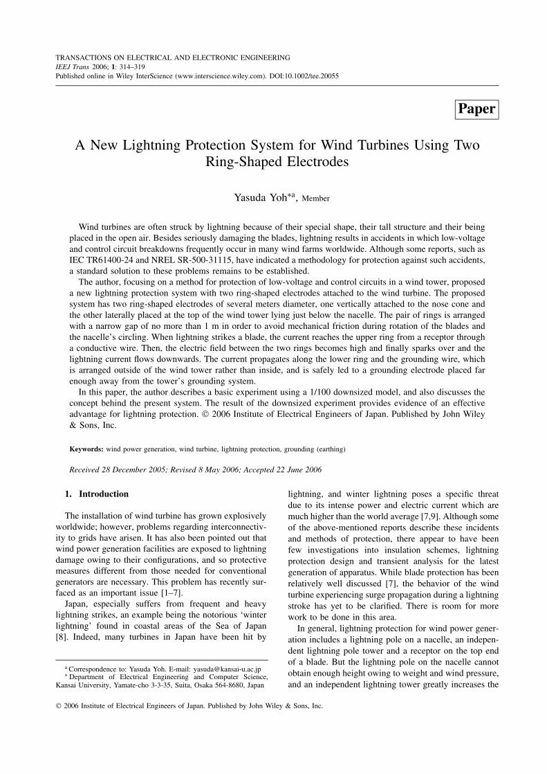
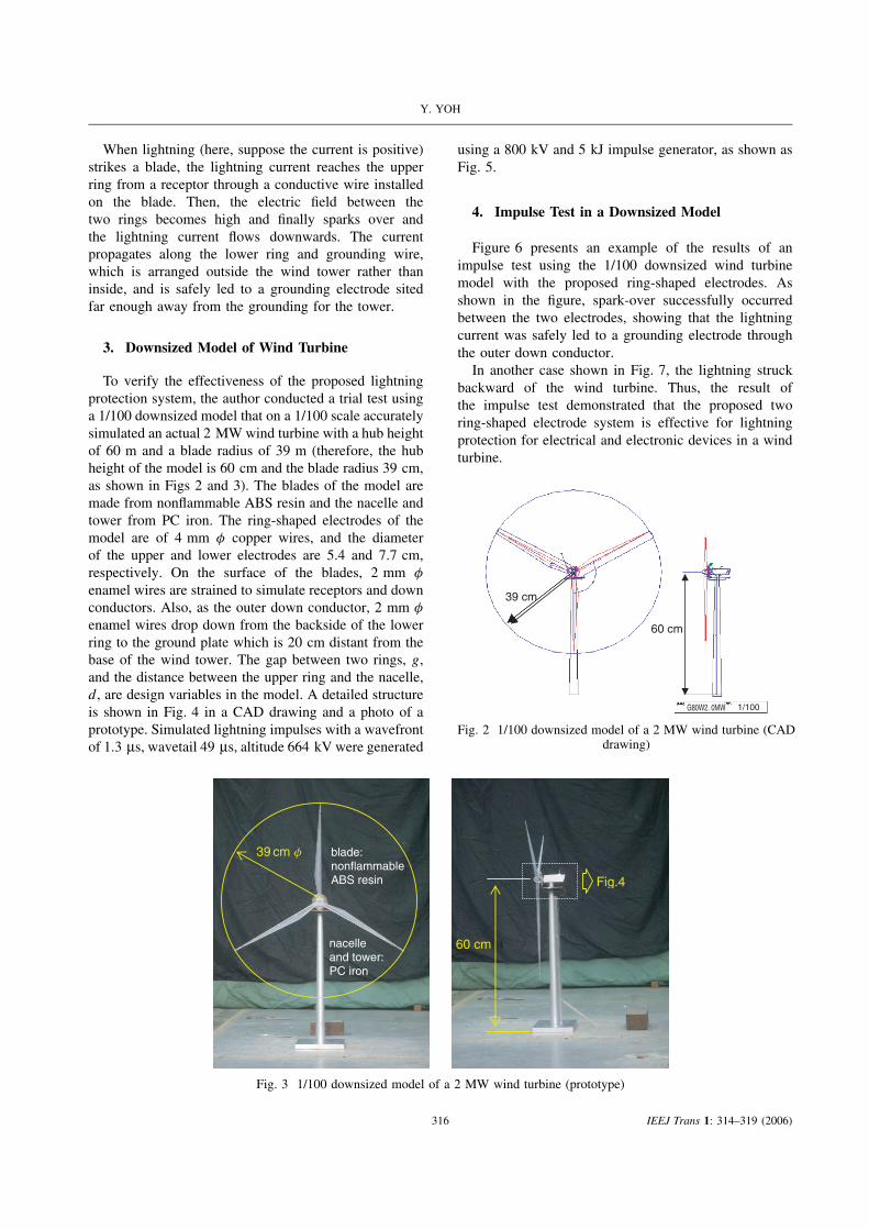
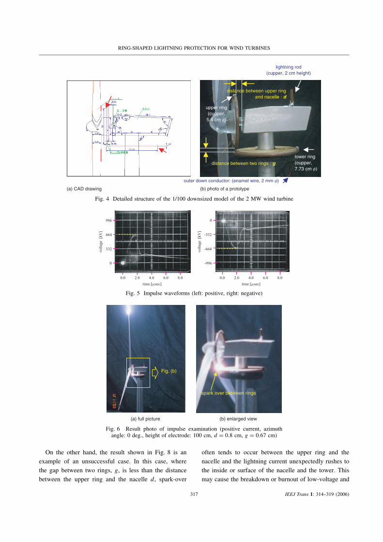
To verify the effectiveness of the proposed lightningprotection system, the author conducted a trial test usinga 1/100 downsized model that on a 1/100 scale accuratelysimulated an actual 2 MW wind turbine with a hub heightof 60 m and a blade radius of 39 m (therefore, the hubheight of the model is 60 cm and the blade radius 39 cm,as shown in Figs 2 and 3). The blades of the model aremade from nonflammable ABS resin and the nacelle andtower from PC iron. The ring-shaped electrodes of themodel are of 4 mm φ copper wires, and the diameterof the upper and lower electrodes are 5.4 and 7.7 cm,respectively. On the surface of the blades, 2 mm φ
enamel wires are strained to simulate receptors and downconductors. Also, as the outer down conductor, 2 mm φ
enamel wires drop down from the backside of the lowerring to the ground plate which is 20 cm distant from thebase of the wind tower. The gap between two rings, g,and the distance between the upper ring and the nacelle,d, are design variables in the model. A detailed structureis shown in Fig. 4 in a CAD drawing and a photo of aprototype. Simulated lightning impulses with a wavefrontof 1.3 µs, wavetail 49 µs, altitude 664 kV were generated
using a 800 kV and 5 kJ impulse generator, as shown asFig. 5.
4. Impulse Test in a Downsized Model
Figure 6 presents an example of the results of animpulse test using the 1/100 downsized wind turbinemodel with the proposed ring-shaped electrodes. Asshown in the figure, spark-over successfully occurredbetween the two electrodes, showing that the lightningcurrent was safely led to a grounding electrode throughthe outer down conductor.
In another case shown in Fig. 7, the lightning struckbackward of the wind turbine. Thus, the result ofthe impulse test demonstrated that the proposed tworing-shaped electrode system is effective for lightningprotection for electrical and electronic devices in a windturbine.
39 cm
60 cm
G80W2. 0MW 1/100
Fig. 2 1/100 downsized model of a 2 MW wind turbine (CADdrawing)
39 cm f
Fig.4
blade:nonflammableABS resin
nacelleand tower:PC iron
60 cm
Fig. 3 1/100 downsized model of a 2 MW wind turbine (prototype)
316 IEEJ Trans 1: 314–319 (2006)
RING-SHAPED LIGHTNING PROTECTION FOR WIND TURBINES
(b) photo of a prototype
upper ring(cupper,5.4 cm f)
distance between upper ringand nacelle : d
outer down conductor: (enamel wire, 2 mm f)
distance between two rings : g
lightning rod(cupper, 2 cm height)
(a) CAD drawing
lower ring(cupper,7.73 cm f)
Fig. 4 Detailed structure of the 1/100 downsized model of the 2 MW wind turbine
time [msec]
664
332
996
0
volta
ge [
kV]
time [msec]
-332
-664
0
-996
volta
ge [
kV]
0.0 2.0 4.0 6.0 8.00.0 2.0 4.0 6.0 8.0
Fig. 5 Impulse waveforms (left: positive, right: negative)
spark over between rings
Fig. (b)
(b) enlarged view (a) full picture
Fig. 6 Result photo of impulse examination (positive current, azimuthangle: 0 deg., height of electrode: 100 cm, d = 0.8 cm, g = 0.67 cm)
On the other hand, the result shown in Fig. 8 is an
example of an unsuccessful case. In this case, where
the gap between two rings, g, is less than the distance
between the upper ring and the nacelle d, spark-over
often tends to occur between the upper ring and the
nacelle and the lightning current unexpectedly rushes to
the inside or surface of the nacelle and the tower. This
may cause the breakdown or burnout of low-voltage and
317 IEEJ Trans 1: 314–319 (2006)

Y. YOH
Fig. (b)
50cm
40cm
spark over between rings
(b) enlarged view (a) full picture
Fig. 7 Result photo of impulse examination. (negative current,azimuth angle: 60 deg., height of electrode: 50 cm, lateral
distance of electrode: 40 cm, d = 0.8 cm, g = 0.67 cm)
(b) enlarged view (a) full picture
Fig. (b)
spark over between rings
also spark overbetween ring and nacelle
Fig. 8 Result photo of impulse examination (negative current,azimuth angle: 0 deg., height of electrode: 100 cm, d = 0.5 cm,
g = 0.52 cm)
control circuits installed in a wind turbine. Moreover,Fig. 9 shows another type of an unsuccessful result,where the lightning directly struck backward of thenacelle in spite of the receptor on the blade.
(b) enlarged view(a) full picture
Fig. (b)
spark over between rings
direct striketo nacelle
60 cm
Fig. 9 Result photo of impulse examination (negative current,azimuth angle: 0 deg., height of electrode: 0 cm, distance of
electrode: 60 cm, d = 0.5 cm, g = 0.52 cm)
The graphs shown in Fig. 10 summarize the aboveresults. Graphs of positive and negative lightning currentsclarify that the gap for the two rings should be designedto be lower than the distance between the upper ring andthe nacelle. Although the result shows that a lower gapmay make for a safer operation, the best solution needs tobe considered from standpoints including the method offixation, the weight of materials, installation costs and theeffect of flexural oscillation of the rings during rotationof the blades.
5. Conclusions
In this paper the author has proposed a novel methodthat utilizes two ring-shaped electrodes for lightningprotection of wind turbines. The most important andinnovative point of the proposed system is a pair of ring-shaped electrodes arranged with a narrow gap, where theair discharges to flow the surge current when a lightningstrikes the wind turbine.
0.0
0.5
1.0
0.0 0.5 1.00.0
0.5
1.0
0.0 0.5 1.0
distance between rings: g [cm]
dist
ance
bet
wee
n up
per
ring
and
nace
lle: d
[cm
]
distance between rings: g [cm]
dist
ance
bet
wee
n up
per
ring
and
nace
lle: d
[cm
] spark over between ringsspark over between rings
spark over between upper ring and nacelle
spark over at both
spark over betweenupper ring and nacelle
spark over at both
(b) negative lightning(a) positive lightning
Fig. 10 Result of impulse examination
318 IEEJ Trans 1: 314–319 (2006)

RING-SHAPED LIGHTNING PROTECTION FOR WIND TURBINES
To demonstrate the validity of the present system, a1/100 downsized model of a wind turbine with ring elec-trodes was manufactured. The results of impulse experi-ments clearly showed that the proposed model can oper-ate safely. Especially, when the gap between the tworings is larger than the distance between the upper ringand the nacelle, it is clear that a spark-over certainlyoccurs and the lightning protection system functions sat-isfactorily. The author is also investigating FDTD elec-tromagnetic calculations for the present model [10,11].It was confirmed that the results of the calculations alsoagree well with the experimental results.
Some problems remain for the proposed method. Forexample, the method of fixation and installation costsneed resolving from a civil engineering viewpoint. Also,any adverse impact on power generation capacity shouldbe discussed from the viewpoint of fluid dynamics.However, in respect of lightning protection, i.e. utilizedcapacity and generating cost, the proposed system canbe expected to maintain the reliability and safety ofoperations for wind power generation.
Acknowledgements
The author thanks Dr. Matsubara Ichiro, former lecturer of OsakaUniversity, for his help in the operation of impulse testing and for afruitful discussion on the methodology of lightning protection. Theauthor also thanks Mr. Yoshioka Takuma, Mr. Fujii Toshiaki andMr. Yamashita Shogo, graduate and undergraduate students of KansaiUniversity, for their help in the impulse tests.
References
(1) “IEEE Recommended Practice for the Electrical Design andOperation of Windfarm Generating Stations”, IEEE Standard1094. 1991.
(2) IEA. Recommended practices for wind turbine testing andevaluation, 9. Lightning Protection for Wind Turbine Installations ,Paris, 1997.
(3) IEE Professional Group S1 (New concepts in the generation,distribution and use of electrical energy): Half-day Colloquiumon “Lightning protection of wind turbines”, 1997; 11.
(4) Sorensen T, Sorensen JT, Nielsen H. Lightning damages topower generating wind turbines, Proceedings of 24 th Interna-tional Conference on Lightning Protection (ICLP98), Birming-ham, UK, 1998; 176–179.
(5) Wind turbine generation systems—24: lightning protection. IECTechnical Report, TR61400-24, 2000.
(6) McNiff B. Wind turbine lightning protection project 1999–2001.NREL Subcontractor Report, SR-500-31115, 2002.
(7) Wada A, Yokoyama S, Numata T, Hirose T. Lightning observa-tion on the nikaho-kogen wind farm. Proceedings of InternationalWorkshop on High Voltage Engineering (IWHV ’04), vol. 1, Sap-poro, Japan, 2004; 51–55 (The papers of Joint Technical Meetingon Electrical Discharges, Switching and Protecting Engineeringand High Voltage Engineering, IEE Japan, ED-04-118, SP-04-29,HV-04-59).
(8) Miyake K, Suzuki T, Takashima M, Takuma M, Tada T. Winterlightning on Japan Sea coast—development of measuring systemon progressing feature of lightning discharge. IEEE Transactionson Power Delivery 1990; 5:1418–1425.
(9) “Chapter 13: Japan”, in “IEA WIND 2004 ANNUAL REPORT”,2005; 147–154.
(10) Yasuda Y, Fujii T. Development of a novel lightning protectionsystem for wind turbine using two ring-shaped electrodes.Proceedings of EXPO World Conference on Wind Energy,Renewable Energy, Fuel Cell (WCWRF2005), Hamamatsu,Japan, on CD-ROM, 2005.
(11) Yasuda Y. Novel lightning protection system for wind turbineusing ring-shaped electrodes. Proceedings of World WindEnergy Conference & Exhibition 2005 (WWEC2005), Melbourne,Australia, on CD-ROM , 2005.
Yasuda Yoh (Member) was born in Tokyo, Japan, onFebruary 15, 1967. He graduatedfrom the Department of Electronicsand Information Engineering, Yoko-hama National University, Japan, in1989. He received the PhD degreefrom the Yokohama National Uni-versity in 1994. Since 1994, he hasbeen with the Department of Elec-trical Engineering (presently, Dept.of Electrical Engineering and Com-
puter Science), Knasai University, Japan, where he ispresently an associate professor. His current researchinterests are development of dispersed generation systemswith small vertical-axis wind turbines (VAWT) and analy-sis and design of lightning protection of wind turbine andwind. He was a recipient of the Excellent Paper Awardfrom IEE of Japan in 1997. He is also a member of IEEE,EWEA (European Wind Energy Association), WWEA(World Wind Energy Association), Japan Wind EnergyAssociation, Japan Solar Energy Society and Japan Insti-tute of Energy.
319 IEEJ Trans 1: 314–319 (2006)