Embed Size (px)
Citation preview
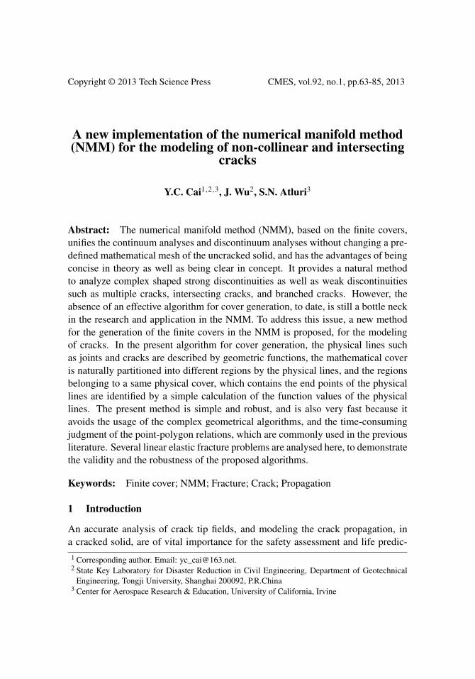
Copyright © 2013 Tech Science Press CMES, vol.92, no.1, pp.63-85, 2013
A new implementation of the numerical manifold method(NMM) for the modeling of non-collinear and intersecting
cracks
Y.C. Cai1,2,3, J. Wu2, S.N. Atluri3
Abstract: The numerical manifold method (NMM), based on the finite covers,unifies the continuum analyses and discontinuum analyses without changing a pre-defined mathematical mesh of the uncracked solid, and has the advantages of beingconcise in theory as well as being clear in concept. It provides a natural methodto analyze complex shaped strong discontinuities as well as weak discontinuitiessuch as multiple cracks, intersecting cracks, and branched cracks. However, theabsence of an effective algorithm for cover generation, to date, is still a bottle neckin the research and application in the NMM. To address this issue, a new methodfor the generation of the finite covers in the NMM is proposed, for the modelingof cracks. In the present algorithm for cover generation, the physical lines suchas joints and cracks are described by geometric functions, the mathematical coveris naturally partitioned into different regions by the physical lines, and the regionsbelonging to a same physical cover, which contains the end points of the physicallines are identified by a simple calculation of the function values of the physicallines. The present method is simple and robust, and is also very fast because itavoids the usage of the complex geometrical algorithms, and the time-consumingjudgment of the point-polygon relations, which are commonly used in the previousliterature. Several linear elastic fracture problems are analysed here, to demonstratethe validity and the robustness of the proposed algorithms.
Keywords: Finite cover; NMM; Fracture; Crack; Propagation
1 Introduction
An accurate analysis of crack tip fields, and modeling the crack propagation, ina cracked solid, are of vital importance for the safety assessment and life predic-1 Corresponding author. Email: [email protected] State Key Laboratory for Disaster Reduction in Civil Engineering, Department of Geotechnical
Engineering, Tongji University, Shanghai 200092, P.R.China3 Center for Aerospace Research & Education, University of California, Irvine
64 Copyright © 2013 Tech Science Press CMES, vol.92, no.1, pp.63-85, 2013
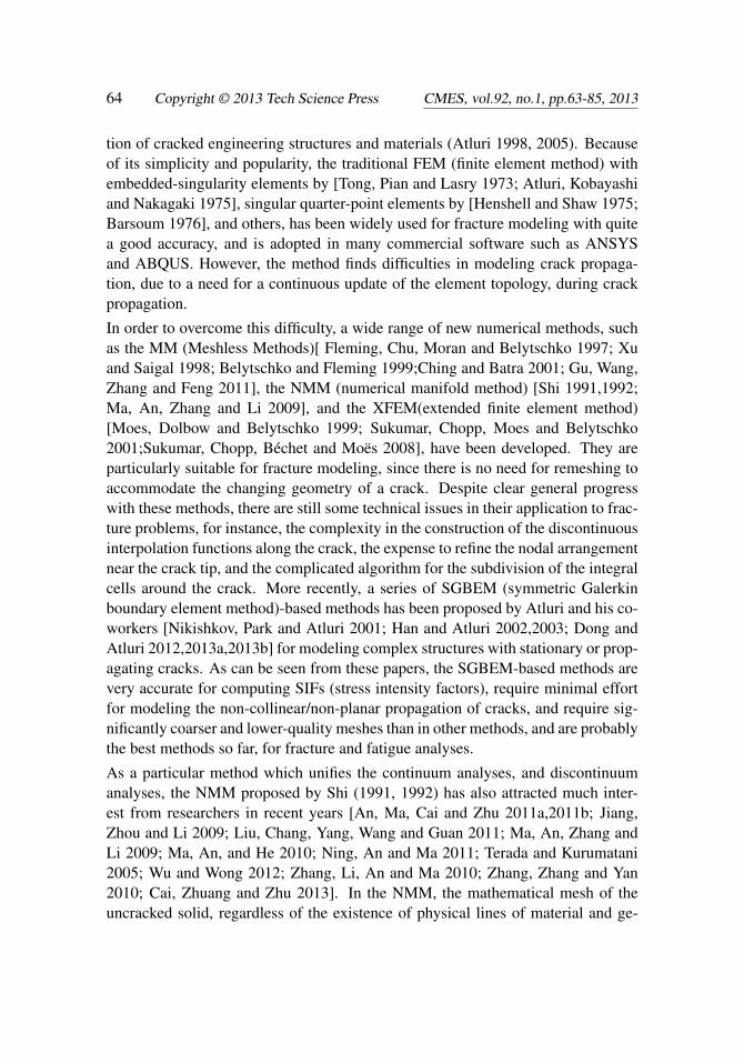
tion of cracked engineering structures and materials (Atluri 1998, 2005). Becauseof its simplicity and popularity, the traditional FEM (finite element method) withembedded-singularity elements by [Tong, Pian and Lasry 1973; Atluri, Kobayashiand Nakagaki 1975], singular quarter-point elements by [Henshell and Shaw 1975;Barsoum 1976], and others, has been widely used for fracture modeling with quitea good accuracy, and is adopted in many commercial software such as ANSYSand ABQUS. However, the method finds difficulties in modeling crack propaga-tion, due to a need for a continuous update of the element topology, during crackpropagation.
In order to overcome this difficulty, a wide range of new numerical methods, suchas the MM (Meshless Methods)[ Fleming, Chu, Moran and Belytschko 1997; Xuand Saigal 1998; Belytschko and Fleming 1999;Ching and Batra 2001; Gu, Wang,Zhang and Feng 2011], the NMM (numerical manifold method) [Shi 1991,1992;Ma, An, Zhang and Li 2009], and the XFEM(extended finite element method)[Moes, Dolbow and Belytschko 1999; Sukumar, Chopp, Moes and Belytschko2001;Sukumar, Chopp, Béchet and Moës 2008], have been developed. They areparticularly suitable for fracture modeling, since there is no need for remeshing toaccommodate the changing geometry of a crack. Despite clear general progresswith these methods, there are still some technical issues in their application to frac-ture problems, for instance, the complexity in the construction of the discontinuousinterpolation functions along the crack, the expense to refine the nodal arrangementnear the crack tip, and the complicated algorithm for the subdivision of the integralcells around the crack. More recently, a series of SGBEM (symmetric Galerkinboundary element method)-based methods has been proposed by Atluri and his co-workers [Nikishkov, Park and Atluri 2001; Han and Atluri 2002,2003; Dong andAtluri 2012,2013a,2013b] for modeling complex structures with stationary or prop-agating cracks. As can be seen from these papers, the SGBEM-based methods arevery accurate for computing SIFs (stress intensity factors), require minimal effortfor modeling the non-collinear/non-planar propagation of cracks, and require sig-nificantly coarser and lower-quality meshes than in other methods, and are probablythe best methods so far, for fracture and fatigue analyses.
As a particular method which unifies the continuum analyses, and discontinuumanalyses, the NMM proposed by Shi (1991, 1992) has also attracted much inter-est from researchers in recent years [An, Ma, Cai and Zhu 2011a,2011b; Jiang,Zhou and Li 2009; Liu, Chang, Yang, Wang and Guan 2011; Ma, An, Zhang andLi 2009; Ma, An, and He 2010; Ning, An and Ma 2011; Terada and Kurumatani2005; Wu and Wong 2012; Zhang, Li, An and Ma 2010; Zhang, Zhang and Yan2010; Cai, Zhuang and Zhu 2013]. In the NMM, the mathematical mesh of theuncracked solid, regardless of the existence of physical lines of material and ge-

A new implementation of the numerical manifold method (NMM) 65
ometric discontinuity (joints and cracks), is first constructed with a defined inter-polation accuracy, and the independent local crack functions are augmented in thephysical covers, which are obtained from the mathematical covers of the uncrackedsolid, as cut by the physical lines (joints and cracks). It provides a natural solution,by using the mathematical and physical cover systems, to accommodate problemdomains with strong discontinuities as well as weak discontinuities, making itselfparticularly suitable for dealing with multiple cracks, intersecting cracks, branchedcracks or other discontinuities. In the NMM, the generation of the finite covers(different influence domains) constitutes a key and essential part of the NMM the-ory. However, to the authors’ knowledge, the absence of an effective algorithm forcover generation, to date, is still a bottle neck in the research and application in theNMM. To address this issue, a simple, fast and robust cover generation method, andalgorithm, is developed, for the modeling of crack problems in this paper. Severalstationary linear elastic fracture problems are analysed, to demonstrate the validityand the robustness of the proposed method.
2 Introduction of the basic theory of the NMM
Consider an arbitrary two-dimensional analysis domain Ω as shown in Fig.1. Thereare three preexisting cracks (chosen as straight lines in this illustration, but canbe general lines of discontinuity) represented by the lines denoted as 1, 2 and 3,respectively. In NMM, a material or geometric discontinuity, such as joint or crack,is called a physical line [Shi 1991,1992; Cai, Zhuang and Zhu 2013].
Figure 1: An arbitrary analysis domain with three physical lines (Lines of Materialor Geometric Discontinuity, i.e., Joints or Cracks)
66 Copyright © 2013 Tech Science Press CMES, vol.92, no.1, pp.63-85, 2013
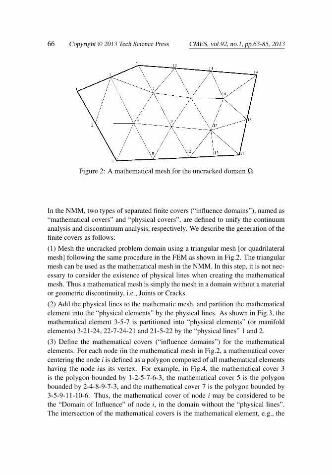
Figure 2: A mathematical mesh for the uncracked domain Ω
In the NMM, two types of separated finite covers (“influence domains”), named as“mathematical covers” and “physical covers”, are defined to unify the continuumanalysis and discontinuum analysis, respectively. We describe the generation of thefinite covers as follows:
(1) Mesh the uncracked problem domain using a triangular mesh [or quadrilateralmesh] following the same procedure in the FEM as shown in Fig.2. The triangularmesh can be used as the mathematical mesh in the NMM. In this step, it is not nec-essary to consider the existence of physical lines when creating the mathematicalmesh. Thus a mathematical mesh is simply the mesh in a domain without a materialor geometric discontinuity, i.e., Joints or Cracks.
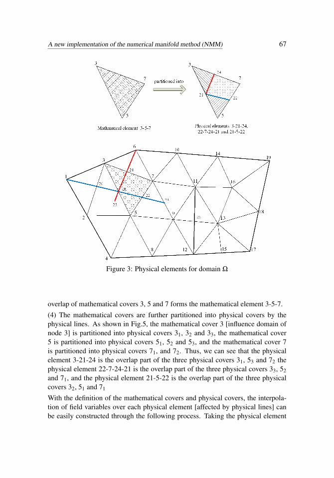
(2) Add the physical lines to the mathematic mesh, and partition the mathematicalelement into the “physical elements” by the physical lines. As shown in Fig.3, themathematical element 3-5-7 is partitioned into “physical elements” (or manifoldelements) 3-21-24, 22-7-24-21 and 21-5-22 by the “physical lines” 1 and 2.
(3) Define the mathematical covers (“influence domains”) for the mathematicalelements. For each node iin the mathematical mesh in Fig.2, a mathematical covercentering the node i is defined as a polygon composed of all mathematical elementshaving the node ias its vertex. For example, in Fig.4, the mathematical cover 3is the polygon bounded by 1-2-5-7-6-3, the mathematical cover 5 is the polygonbounded by 2-4-8-9-7-3, and the mathematical cover 7 is the polygon bounded by3-5-9-11-10-6. Thus, the mathematical cover of node i may be considered to bethe “Domain of Influence” of node i, in the domain without the “physical lines”.The intersection of the mathematical covers is the mathematical element, e.g., the
A new implementation of the numerical manifold method (NMM) 67
Figure 3: Physical elements for domain Ω
overlap of mathematical covers 3, 5 and 7 forms the mathematical element 3-5-7.
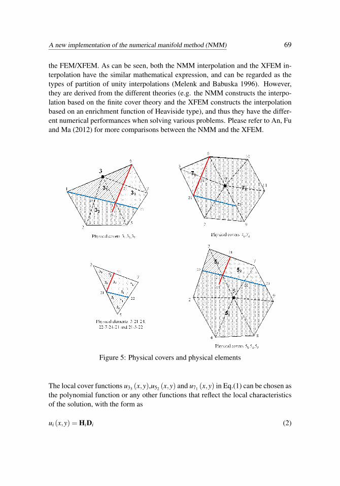
(4) The mathematical covers are further partitioned into physical covers by thephysical lines. As shown in Fig.5, the mathematical cover 3 [influence domain ofnode 3] is partitioned into physical covers 31, 32 and 33, the mathematical cover5 is partitioned into physical covers 51, 52 and 53, and the mathematical cover 7is partitioned into physical covers 71, and 72. Thus, we can see that the physicalelement 3-21-24 is the overlap part of the three physical covers 31, 53 and 72 thephysical element 22-7-24-21 is the overlap part of the three physical covers 33, 52and 71, and the physical element 21-5-22 is the overlap part of the three physicalcovers 32, 51 and 71
With the definition of the mathematical covers and physical covers, the interpola-tion of field variables over each physical element [affected by physical lines] canbe easily constructed through the following process. Taking the physical element
68 Copyright © 2013 Tech Science Press CMES, vol.92, no.1, pp.63-85, 2013
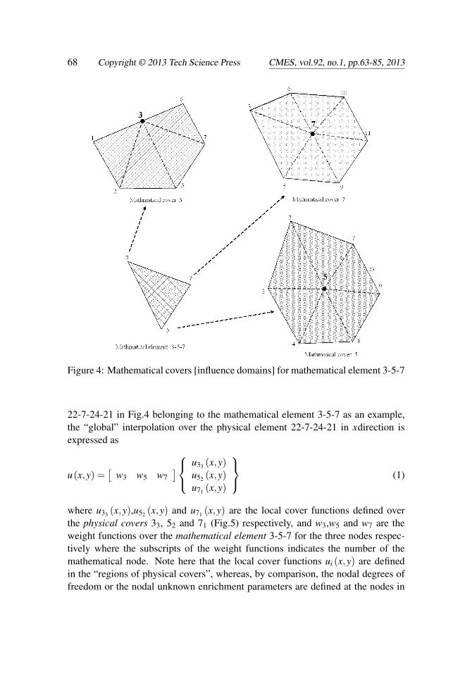
Figure 4: Mathematical covers [influence domains] for mathematical element 3-5-7
22-7-24-21 in Fig.4 belonging to the mathematical element 3-5-7 as an example,the “global” interpolation over the physical element 22-7-24-21 in xdirection isexpressed as
u(x,y) =[
w3 w5 w7]
u33 (x,y)u52 (x,y)u71 (x,y)
(1)
where u33 (x,y),u52 (x,y) and u71 (x,y) are the local cover functions defined overthe physical covers 33, 52 and 71 (Fig.5) respectively, and w3,w5 and w7 are theweight functions over the mathematical element 3-5-7 for the three nodes respec-tively where the subscripts of the weight functions indicates the number of themathematical node. Note here that the local cover functions ui (x,y) are definedin the “regions of physical covers”, whereas, by comparison, the nodal degrees offreedom or the nodal unknown enrichment parameters are defined at the nodes in
A new implementation of the numerical manifold method (NMM) 69
the FEM/XFEM. As can be seen, both the NMM interpolation and the XFEM in-terpolation have the similar mathematical expression, and can be regarded as thetypes of partition of unity interpolations (Melenk and Babuska 1996). However,they are derived from the different theories (e.g. the NMM constructs the interpo-lation based on the finite cover theory and the XFEM constructs the interpolationbased on an enrichment function of Heaviside type), and thus they have the differ-ent numerical performances when solving various problems. Please refer to An, Fuand Ma (2012) for more comparisons between the NMM and the XFEM.
Figure 5: Physical covers and physical elements
The local cover functions u33 (x,y),u52 (x,y) and u71 (x,y) in Eq.(1) can be chosen asthe polynomial function or any other functions that reflect the local characteristicsof the solution, with the form as
ui (x,y) = HiDi (2)
70 Copyright © 2013 Tech Science Press CMES, vol.92, no.1, pp.63-85, 2013
where Di =[
di1 di2 · · ·]T are the generalized degrees of freedom over physi-
cal cover Ci and Hi is the basis function. In this study, we take Hi = [1] for commonphysical covers and Hi = [ 1
√r sin θ
2√
r cos θ
2√
r sin θ
2 sinθ√
r cos θ
2 sinθ ]for the physical covers near a crack tip, where (r,θ) is the local coordinate systemat the crack tip. The J integral is used to compute the stress intensity factors (SIFs)over the crack tip.
The weight functions w3,w5 and w7 in Eq.(1) are calculated by
wi =1
2A(ai +bix+ ciy) (3)
ai = x jym− xmy j, bi = y j− ym, ci =−x j + xm (4)
in which, A is the area of the triangular mathematical element 3-5-7, and i = 3,5,7;j = 5,7,3; m = 7,3,5.
We see that, the global function in Eq.(1) is actually constructed, by multiplyingthe weight functions wi (x,y) from the mathematical mesh, with the local functionsui (x,y) from the physical covers which are obtained from the mathematical coverscut by physical lines (cracks or joints). When there is no physical line involved in aphysical element and the local function is taken as ui (x,y) = di1, the interpolationin Eq.(1) is reduced to the general FEM triangular interpolation.
Similarly the displacement function over physical element 3-21-24 in Fig.5 in xdirectionis expressed as
u(x,y) =[
w3 w5 w7]
u31 (x,y)u53 (x,y)u72 (x,y)
(5)
The interpolation over the physical element in y direction can be defined followingan identical process.
By comparing Eq. (1) with Eq. (5), it can be found that same weight functions w2,w5 and w7 are used for the physical elements 22-7-24-21 and 3-21-24 in Fig. 5.However as the physical covers 33, 52 and 71 of the physical element 22-7-24-21,and the physical covers 31, 53 and 72 of the physical element 3-21-24 are sepa-rately defined and have different degrees of freedoms, the discontinuity of the dis-placement jump over the interface 21-24 of the adjacent elements 22-7-24-21 and3-21-24 can be easily captured while the mathematical mesh remain unchanged.This means in the NMM, the analysis of moving interface problems such as crackpropagation and discontinuous deformation, can be performed until the end stagesof failure, without the need for changing predefined mathematical mesh.
A new implementation of the numerical manifold method (NMM) 71
3 A simple and robust method for the generation of the finite covers
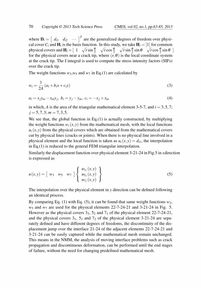
From the above introduction, it can be seen that, in the NMM, the mathematicalmesh, ignoring the existence of physical lines is first constructed to define the in-terpolation accuracy, and the independent local cover functions are then defined atthe physical covers which are obtained from the mathematical covers, as cut by thephysical lines. It unifies the continuum analysis and discontinuum analysis with-out changing the predefined mathematical mesh, and has the advantages of beingconcise in theory as well as being clear in concept.
Figure 6: Generation of physical cover 3
72 Copyright © 2013 Tech Science Press CMES, vol.92, no.1, pp.63-85, 2013
A key and essential part in the implementation of the NMM is the generation ofthe finite covers, which includes the partitioning of independent physical coversand the indentification of the relations between physical covers and physical ele-ments. For example, for the mathematical cover 3 in Fig.5, the simplest idea forthe generation of the finite covers is to search out the closed regions 6-3-1-20-21-24, 1-2-5-22-21-20 and 22-7-6-24-21 by using the geometry algorithms, and recordthem as the independent physical covers 31, 32 and 33 respectively. Then the phys-ical cover numbers of the physical element can be found out through the relativeposition between the integral points of the physical element and the physical covers.This method seems to be very simple, but actually it is quite difficult to be imple-mented in the NMM, due to the usage of the complex geometry algorithms and thetime-consuming judgment of the point-polygon relations, especially for three di-mensional analyses. Up to now, the absence of an effective cover generation theoryis still the bottle neck of the research and application of the NMM.
In the following, a novel simple and robust cover generation method is developedto address the above-mentioned issue in the NMM. The algorithmic steps are:
(1) Take the mathematical cover 3 which is bounded by 1-2-5-7-6-3 (Fig.2). It canbe easily found that the mathematical cover 3 is partitioned by the physical lines1 and 2. We suppose that the physical line 1 is described by function F1 (x) = 0and the physical line 2 is described by function F2 (x) = 0, denoted as F10 and F20respectively. The physical line 1 partitions the mathematical cover 3 into two partsF1 (x) > 0 and F1 (x) < 0, denoted as F1A and F1B respectively. The physicalline 2 partitions the mathematical cover 3 into two parts F2 (x) > 0and F2 (x) < 0,denoted as F2A and F2B respectively, as shown in Fig.6.
(2) Record the 2ndifferent regions, which are obtained from the mathematical coveri partitioned by n physical lines, with a 2n× nmatrix Ri. For example, the mathe-matical cover 3 in Fig.6 is partitioned into 4 regions by the physical lines 1 and 2,which can be recorded as
Ri =
F1B,F2BF1A,F2BF1A,F2AF1B,F2A
(3) The position of the tip point 25 of the physical line 1 falls into the interior ofthe mathematical cover 3. According to the definition of the physical covers, theregions
(F1A,F2B
)and
(F1A,F2A
)belong to a same physical cover 32 because(
F1A,F2B)
and(F1A,F2A
)are not totally separated by the physical line and they
don’t have the independent deformations, as shown in Fig.6. To deal with this caseautomatically, we extend the tip point 25 to point P, where P should be outside of
A new implementation of the numerical manifold method (NMM) 73
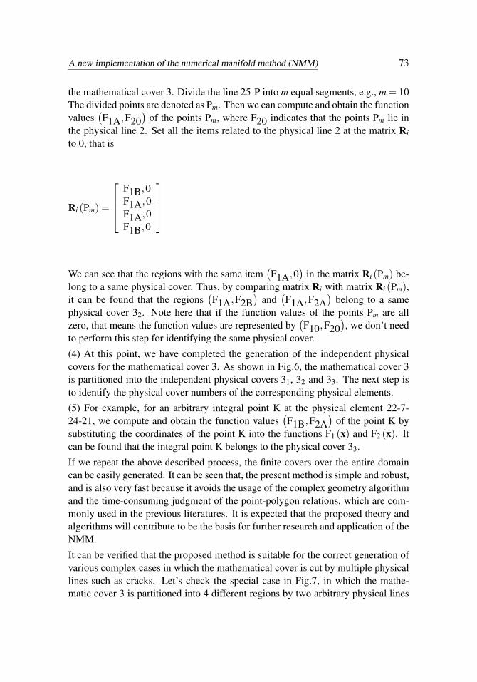
the mathematical cover 3. Divide the line 25-P into m equal segments, e.g., m = 10The divided points are denoted as Pm. Then we can compute and obtain the functionvalues
(F1A,F20
)of the points Pm, where F20 indicates that the points Pm lie in
the physical line 2. Set all the items related to the physical line 2 at the matrix Ri
to 0, that is
Ri (Pm) =
F1B,0F1A,0F1A,0F1B,0
We can see that the regions with the same item(F1A,0
)in the matrix Ri (Pm) be-
long to a same physical cover. Thus, by comparing matrix Ri with matrix Ri (Pm),it can be found that the regions
(F1A,F2B
)and
(F1A,F2A
)belong to a same
physical cover 32. Note here that if the function values of the points Pm are allzero, that means the function values are represented by
(F10,F20
), we don’t need
to perform this step for identifying the same physical cover.
(4) At this point, we have completed the generation of the independent physicalcovers for the mathematical cover 3. As shown in Fig.6, the mathematical cover 3is partitioned into the independent physical covers 31, 32 and 33. The next step isto identify the physical cover numbers of the corresponding physical elements.
(5) For example, for an arbitrary integral point K at the physical element 22-7-24-21, we compute and obtain the function values
(F1B,F2A
)of the point K by
substituting the coordinates of the point K into the functions F1 (x) and F2 (x). Itcan be found that the integral point K belongs to the physical cover 33.
If we repeat the above described process, the finite covers over the entire domaincan be easily generated. It can be seen that, the present method is simple and robust,and is also very fast because it avoids the usage of the complex geometry algorithmand the time-consuming judgment of the point-polygon relations, which are com-monly used in the previous literatures. It is expected that the proposed theory andalgorithms will contribute to be the basis for further research and application of theNMM.
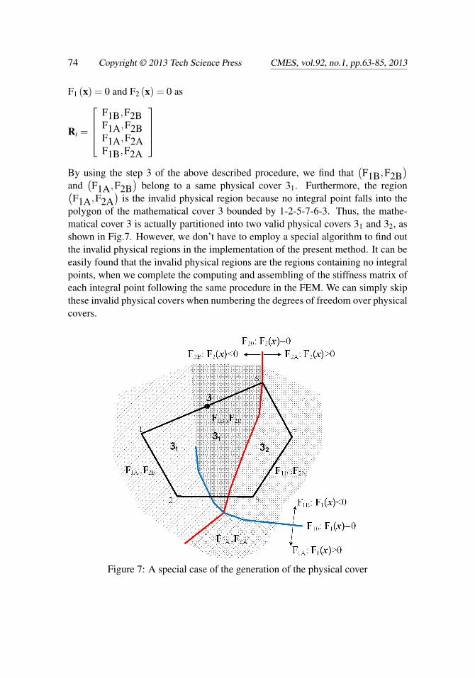
It can be verified that the proposed method is suitable for the correct generation ofvarious complex cases in which the mathematical cover is cut by multiple physicallines such as cracks. Let’s check the special case in Fig.7, in which the mathe-matic cover 3 is partitioned into 4 different regions by two arbitrary physical lines
74 Copyright © 2013 Tech Science Press CMES, vol.92, no.1, pp.63-85, 2013
F1 (x) = 0 and F2 (x) = 0 as
Ri =
F1B,F2BF1A,F2BF1A,F2AF1B,F2A
By using the step 3 of the above described procedure, we find that
(F1B,F2B
)and
(F1A,F2B
)belong to a same physical cover 31. Furthermore, the region(
F1A,F2A)
is the invalid physical region because no integral point falls into thepolygon of the mathematical cover 3 bounded by 1-2-5-7-6-3. Thus, the mathe-matical cover 3 is actually partitioned into two valid physical covers 31 and 32, asshown in Fig.7. However, we don’t have to employ a special algorithm to find outthe invalid physical regions in the implementation of the present method. It can beeasily found that the invalid physical regions are the regions containing no integralpoints, when we complete the computing and assembling of the stiffness matrix ofeach integral point following the same procedure in the FEM. We can simply skipthese invalid physical covers when numbering the degrees of freedom over physicalcovers.
Figure 7: A special case of the generation of the physical cover
A new implementation of the numerical manifold method (NMM) 75
4 Numerical examples
4.1 Central-cracked plate
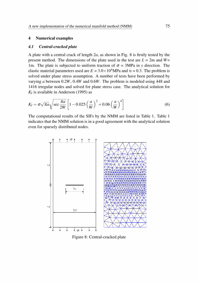
A plate with a central crack of length 2a, as shown in Fig. 8 is firstly tested by thepresent method. The dimensions of the plate used in the test are L = 2m and W=1m. The plate is subjected to uniform traction of σ = 3MPa in y direction. Theelastic material parameters used are E = 3.0×10⁴MPa and υ = 0.3. The problem issolved under plane stress assumption. A number of tests have been performed byvarying a between 0.2W , 0.4W and 0.6W . The problem is modeled using 448 and1416 irregular nodes and solved for plane stress case. The analytical solution forKI is available in Anderson (1995) as
KI = σ√
πa√
secπa2W
[1−0.025
( aW
)2+0.06
( aW
)4]
(6)
The computational results of the SIFs by the NMM are listed in Table 1. Table 1indicates that the NMM solution is in a good agreement with the analytical solutioneven for sparsely distributed nodes.
Figure 8: Central-cracked plate
76 Copyright © 2013 Tech Science Press CMES, vol.92, no.1, pp.63-85, 2013
Table 1: SIFs for the central-cracked plate
a/W448 nodes 1416 nodes
AnalyticalKI Error KI Error0.2 2.4150 -0.87% 2.4313 -0.20% 2.43620.4 3.6638 -1.77% 3.6863 -1.16% 3.72970.6 5.2837 -1.53% 5.2952 -1.32% 5.3658
4.2 Three-point bend specimen
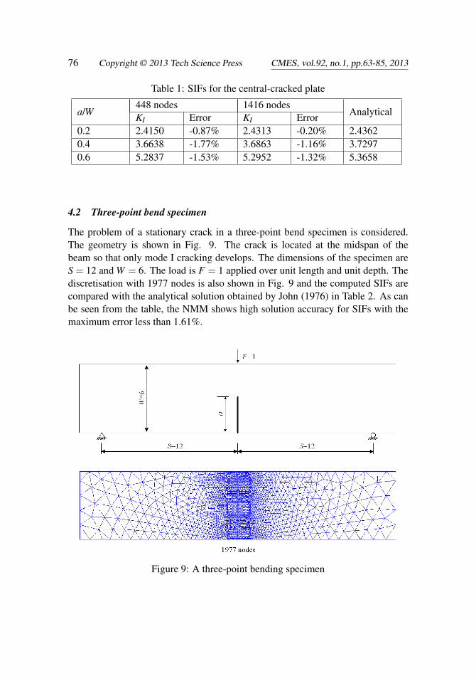
The problem of a stationary crack in a three-point bend specimen is considered.The geometry is shown in Fig. 9. The crack is located at the midspan of thebeam so that only mode I cracking develops. The dimensions of the specimen areS = 12 and W = 6. The load is F = 1 applied over unit length and unit depth. Thediscretisation with 1977 nodes is also shown in Fig. 9 and the computed SIFs arecompared with the analytical solution obtained by John (1976) in Table 2. As canbe seen from the table, the NMM shows high solution accuracy for SIFs with themaximum error less than 1.61%.
Figure 9: A three-point bending specimen
A new implementation of the numerical manifold method (NMM) 77
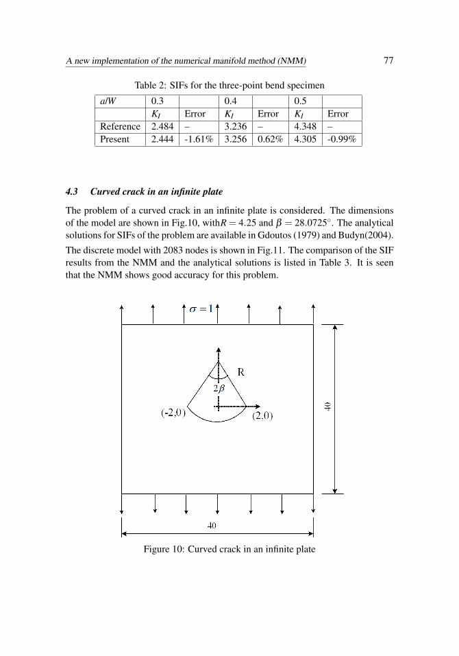
Table 2: SIFs for the three-point bend specimen
a/W 0.3 0.4 0.5KI Error KI Error KI Error
Reference 2.484 – 3.236 – 4.348 –Present 2.444 -1.61% 3.256 0.62% 4.305 -0.99%
4.3 Curved crack in an infinite plate
The problem of a curved crack in an infinite plate is considered. The dimensionsof the model are shown in Fig.10, withR = 4.25 and β = 28.0725. The analyticalsolutions for SIFs of the problem are available in Gdoutos (1979) and Budyn(2004).
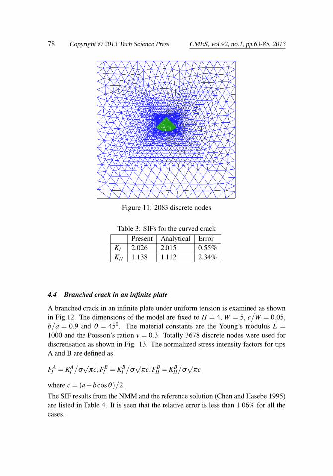
The discrete model with 2083 nodes is shown in Fig.11. The comparison of the SIFresults from the NMM and the analytical solutions is listed in Table 3. It is seenthat the NMM shows good accuracy for this problem.
Figure 10: Curved crack in an infinite plate
78 Copyright © 2013 Tech Science Press CMES, vol.92, no.1, pp.63-85, 2013
Figure 11: 2083 discrete nodes
Table 3: SIFs for the curved crackPresent Analytical Error
KI 2.026 2.015 0.55%KII 1.138 1.112 2.34%
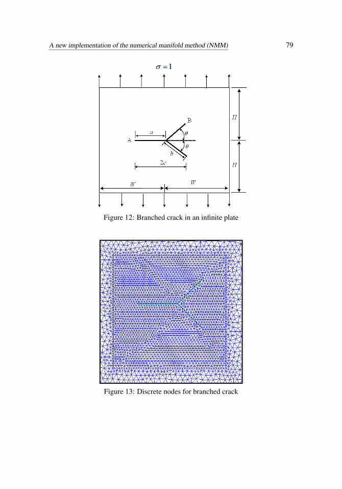
4.4 Branched crack in an infinite plate
A branched crack in an infinite plate under uniform tension is examined as shownin Fig.12. The dimensions of the model are fixed to H = 4, W = 5, a
/W = 0.05,
b/
a = 0.9 and θ = 450. The material constants are the Young’s modulus E =1000 and the Poisson’s ration v = 0.3. Totally 3678 discrete nodes were used fordiscretisation as shown in Fig. 13. The normalized stress intensity factors for tipsA and B are defined as
FAI = KA
I/
σ√
πc,FBI = KB
I/
σ√
πc,FBII = KB
II/
σ√
πc
where c = (a+bcosθ)/
2.
The SIF results from the NMM and the reference solution (Chen and Hasebe 1995)are listed in Table 4. It is seen that the relative error is less than 1.06% for all thecases.
A new implementation of the numerical manifold method (NMM) 79
Figure 12: Branched crack in an infinite plate
Figure 13: Discrete nodes for branched crack
80 Copyright © 2013 Tech Science Press CMES, vol.92, no.1, pp.63-85, 2013
Table 4: SIFs for branched crack in an infinite plate
Present Analytical ErrorFA
I 1.029 1.040 -1.06%FB
I 0.492 0.495 -0.61%FB
II 0.501 0.503 -0.40%
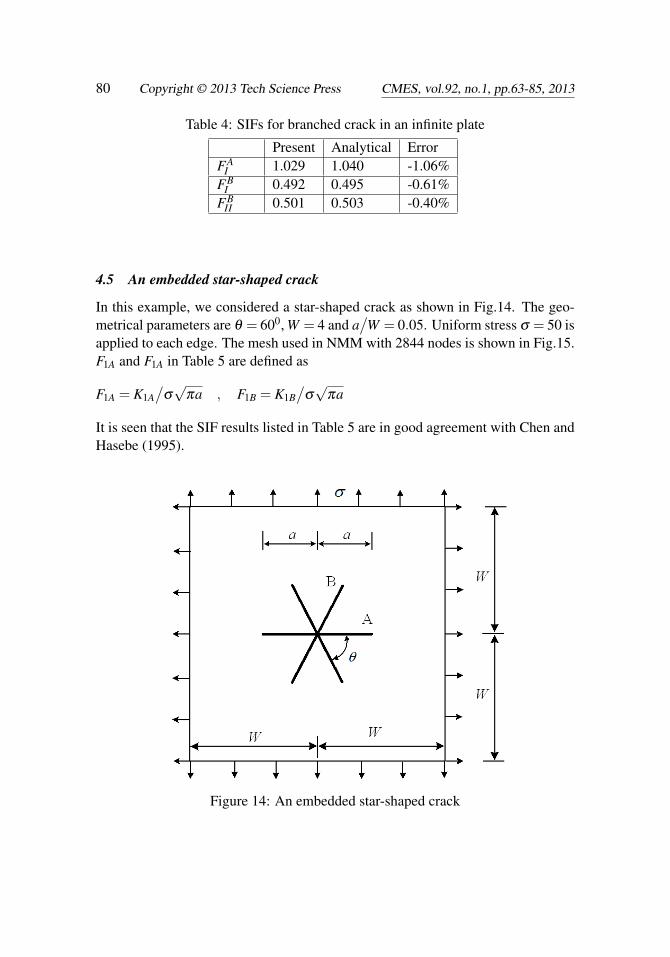
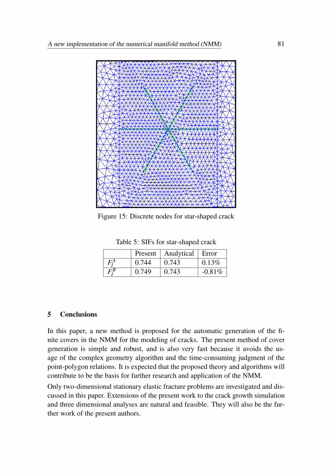
4.5 An embedded star-shaped crack
In this example, we considered a star-shaped crack as shown in Fig.14. The geo-metrical parameters are θ = 600, W = 4 and a
/W = 0.05. Uniform stress σ = 50 is
applied to each edge. The mesh used in NMM with 2844 nodes is shown in Fig.15.F1A and F1A in Table 5 are defined as
F1A = K1A/
σ√
πa , F1B = K1B/
σ√
πa
It is seen that the SIF results listed in Table 5 are in good agreement with Chen andHasebe (1995).
Figure 14: An embedded star-shaped crack
A new implementation of the numerical manifold method (NMM) 81
Figure 15: Discrete nodes for star-shaped crack
Table 5: SIFs for star-shaped crack
Present Analytical ErrorFA
I 0.744 0.743 0.13%FB
I 0.749 0.743 -0.81%
5 Conclusions
In this paper, a new method is proposed for the automatic generation of the fi-nite covers in the NMM for the modeling of cracks. The present method of covergeneration is simple and robust, and is also very fast because it avoids the us-age of the complex geometry algorithm and the time-consuming judgment of thepoint-polygon relations. It is expected that the proposed theory and algorithms willcontribute to be the basis for further research and application of the NMM.
Only two-dimensional stationary elastic fracture problems are investigated and dis-cussed in this paper. Extensions of the present work to the crack growth simulationand three dimensional analyses are natural and feasible. They will also be the fur-ther work of the present authors.
82 Copyright © 2013 Tech Science Press CMES, vol.92, no.1, pp.63-85, 2013
Acknowledgements
The authors gratefully acknowledge the support of National Basic Research Pro-gram of China (973 Program: 2011CB013800), New Century Excellent TalentsProject in China (NCET-12-0415), Program for Changjiang Scholars and Innova-tive Research Team in University (PCSIRT, IRT1029), and Fundamental ResearchFunds for the Central Universities.
References
An, X. M.; Fu, G.Y.; Ma, G.W. (2012): A comparison between the NMM and theXFEM in discontinuity modeling International Journal of Computational Methods,vol. 9, issue 2 DOI: 10.1142/S0219876212400300.
An, X.M.; Ma, G.W.; Cai, Y.C.; Zhu, H.H. (2011a): A new way to treat materialdiscontinuities in the numerical manifold method. Computer Methods in AppliedMechanics and Engineering, vol.20, pp. 3296-3308.
An, X.M.; Ma, G.W.; Cai, Y.C; Zhu, H.H. (2011b): Arbitrary discontinuities inthe numerical manifold method. International Journal of Computational Methods,vol. 8, pp. 315-347.
Anderson, T.L.(1995): Fracture mechanics: foundamentals and application. 2nd
Edition. Boca Raton:CRC.
Atluri, S. N. (1998): Structural Integrity and Durability, Forsyth: Tech SciencePress.
Atluri, S.N. (2005): Methods of computer modeling in engineering and the sci-ences. Tech Science Press.
Atluri, S. N.; Kobayashi, A. S.; Nakagaki M. (1975): An assumed displacementhybrid finite element model for linear fracture mechanics, International Journal ofFracture, vol. 11, no. 2, pp. 257-271.
Barsoum, R. S. (1976): On the use of isoparametric finite elements in linearfracture mechanics. International Journal for Numerical Methods in Engineering,Vol.10, issue 1, pp. 25-37.
Belytschko T.; Fleming M.(1999): Smoothing, enrichment and contact in theelement-free Galerkin method. Computers and Structures, vol. 71, pp.173-195.
Budyn, E.R.L.(2004): Mutiple crack growth by the extended finite element method.Northwestern University.
Cai, Y.C.; Zhuang X.Y.; Zhu, H.H.(2013): A generalized and efficient methodfor finite cover generation in the numerical manifold method. International Journalof Computational Methods, vol.10, DOI: 10.1142/S021987621350028X.
A new implementation of the numerical manifold method (NMM) 83
Chen Y.; Hasebe N(1995): New integration scheme for the branch crack problem.Engineering Fracture Mechanics, vol. 52, pp.791801.
Ching H.-K.; Batra R. C.(2001): Determination of crack tip fields in linear elasto-statics by the Meshless Local Petrov-Galerkin (MLPG) method. CMES: ComputerModeling in Engineering & Sciences, vol. 2, no. 2, pp. 273-290.
Dong, L.; Atluri, S. N. (2012): SGBEM (using non-hyper-singular traction BIE),and super elements, for non-collinear fatigue-growth analyses of cracks in stiffenedpanels with composite-patch repairs. CMES: Computer Modeling in Engineering& Sciences, vol.89, no.5, pp.417-458.
Dong, L.; Atluri, S.N. (2013a): Fracture & fatigue analyses: SGBEM-FEM orXFEM? Part 1: 2D structures. CMES: Computer Modeling in Engineering & Sci-ences, vol.90, no.2, pp. 91-146.
Dong, L.; Atluri, S.N. (2013b): Fracture & fatigue analyses: SGBEM-FEM orXFEM? Part 2: 3D solids. CMES: Computer Modeling in Engineering & Sciences,vol.90, no.5, pp 379-413.
Fleming, M.;Chu,Y.A.;Moran, B.;Belytschko, T.(1997): Enriched element-freeGalerkin methods for crack tip fields. International journal for numerical methodsin engineering, vol.40, pp.1483-1504.
Gdoutos, E.(1979): Fracture mechanics. Boston:Kluver Academics Publisher.
Gu, YT.; Wang W.; Zhang LC.; Feng XQ.(2011): An enriched radial point in-terpolation method (e-RPIM) for analysis of crack tip fields. Engineering FractureMechanics, vol.78, pp.175–190.
Han, Z. D.; Atluri, S. N. (2002): SGBEM (for Cracked Local Subdomain) – FEM(for uncracked global Structure) alternating method for analyzing 3D surface cracksand their fatigue-growth. CMES: Computer Modeling in Engineering & Sciences,vol.3, no.6, pp.699-716.
Han, Z. D.; Atluri, S. N. (2003): On simple formulations of weakly-singular trac-tion & displacement BIE, and their solutions through Petrov-Galerkin approaches.CMES: Computer Modeling in Engineering & Sciences, vol.4, no.1, pp.5-20.
Henshell, R. D.; Shaw, K. G. (1975): Crack tip finite elements are unneces-sary. International Journal for Numerical Methods in Engineering, vol. 9, issue3, pp.495-507.
Jiang, Q.H.; Zhou, C.B; and Li, D.Q. (2009): A three-dimensional numericalmanifold method based on tetrahedral meshes. Computers & Structures, vol. 87,pp. 880-889.
John ES.(1976): Wide range stress intensity factor expressions for ASTM E399standard fracture toughness specimens. International Journal of Fracture, vol.12,
84 Copyright © 2013 Tech Science Press CMES, vol.92, no.1, pp.63-85, 2013
pp.475-476.
Liu, Y.R.; Chang, Q.; Yang, Q.; Wang, C.Q.; Guan, F.H. (2011): Fractureanalysis of rock mass based on 3-D nonlinear Finite Element Method. ScienceChina-Technological Sciences, vol. 54, pp. 556-564.
Ma, G.W.; An, X.M.; Zhang, H.H.; Li, L.X. (2009). Modeling complex crackproblems with numerical manifold method. International Journal of Fracture, vol.156, pp. 21-35.
Ma, G.W.; An, X.M.; He, L. (2010): The numerical manifold method: a review.International Journal of Computational Methods, vol. 7, pp. 1-32.
Melenk J M; Babuska I. (1996): The partition of unity finite element method:basic theory and applications Computer Methods in Applied Mechanics and Engi-neering, vol. 39, pp. 289–314.
Moes N.; Dolbow, J. O. H. N.; Belytschko, T. (1999): A finite element methodfor crack growth without remeshing. International journal for numerical methodsin engineering, vol. 46, no.1, pp. 131-150.
Nikishkov, G. P..; Park, J. H.; Atluri, S. N. (2001): SGBEM-FEM alternatingmethod for analyzing 3D non-planar cracks and their growth in structural compo-nents. CMES: Computer Modeling in Engineering & Sciences, vol.2, no.3, pp.401-422.
Ning, Y.J.; An, X.M.; Ma, G.W. (2011): Footwall slope stability analysis with thenumerical manifold method. International Journal of Rock Mechanics & MiningSciences, vol.48, pp. 964-975.
Shi, G.H. (1991): Manifold method of material analysis. Trans. 9th Army Conf.Applied Mathematics and Computing, Minneapolis, Minnesota pp. 57-76.
Shi, G.H. (1992): Modeling rock joints and blocks by manifold method. RockMech. Proc. 33rd U. S. Symposium, Santa Fe, New Mexico, pp. 639-648.
Sukumar, N.; Chopp, D. L.; Moes, N., Belytschko, T. (2001): Modeling holesand inclusions by level sets in the extended finite-element method. Computer meth-ods in applied mechanics and engineering, vol. 190, no. 46, pp. 6183-6200.
Sukumar, N.; Chopp, D. L.; Béchet, E.; Moës, N. (2008): Three-dimensionalnon-planar crack growth by a coupled extended finite element and fast marchingmethod. International journal for numerical methods in engineering, vol. 76,issue5, pp. 727-748.
Terada, K.; Kurumatani, M. (2005): An integrated procedure for three-dimensionalstructural analysis with the finite cover method. International Journal for Numeri-cal Methods in Engineering, vol. 63, pp. 2102-2123.
Tong, P; Pian T. H. H; Lasry S. J. (1973): A hybrid-element approach to crack
A new implementation of the numerical manifold method (NMM) 85
problems in plane elasticity. International Journal for Numerical Methods in En-gineering, vol. 7, issue 3, pp. 297-308.
Wu,Z.J.; Wong, L.N.Y.(2012):Frictional crack initiation and propagation analysisusing the numerical manifold method. Computers and Geotechnics, vol.39, pp.38-53.
Xu, Y.; Saigal S.(1998): An element free Galerkin formulation for stable crackgrowth in an elastic solid. Computer Methods in Applied Mechanics and Engineer-ing, vol.154, pp.331-343.
Zhang, H.H.; Li, L.X.; An, X.M.; Ma, G.W. (2010): Numerical analysis of 2-Dcrack propagation problems using the numerical manifold method. EngineeringAnalysis with Boundary Elements, vol. 34, pp.41-50.
Zhang, Z.R.; Zhang, X.W.; Yan, J.H. (2010): Manifold method coupled velocityand pressure for Navier-Stokes equations and direct numerical solution of unsteadyincompressible viscous flow. Computers & Fluids, vol. 39, pp. 1353-1365.