Embed Size (px)
Citation preview
A NEW EXTENDED BANDWIDTH ESCAN L-BAND & S-BAND TRACKING ANTENNA
Item Type text; Proceedings
Authors COOK, JAMES H., JR.; KOSTER, A. RENEE
Publisher International Foundation for Telemetering
Journal International Telemetering Conference Proceedings
Rights Copyright © International Foundation for Telemetering
Download date 15/05/2018 03:52:52
Link to Item http://hdl.handle.net/10150/613430
Patent Pending1
A NEW EXTENDED BANDWIDTH ESCAN L-BAND & S-BANDTRACKING ANTENNA
JAMES H. COOK, JR. and A. RENEE KOSTERSCIENTIFIC-ATLANTA, INC.
ABSTRACT
The design and performance of a 1435 MHZ to 2600 MHZ ESCAN1
feed will be discussed. The radiation characteristics of avery small (<10 wavelengths) reflector antenna will bepresented. The ESCAN tracking concept offers a significantimprovement in the effective gain, sidelobes and trackingperformance for broadband telemetry trackers over previous,low-cost approaches. The tradeoffs associated with theoptimization of the ESCAN antenna’s radiation performancewill be presented along with a comparison of conical scanand single channel monopulse performance. The tradeoffs willinclude an analysis of the limitations in performance due tocentral blockage, aperture illumination, spillover, and comaeffects of an “effective” off-axis feed for a small,paraboloidal reflector antenna.
INTRODUCTION
The design of a small tracking antenna is usually the resultof a tradeoff of several parameters, such as bandwidth,gain, sidelobes, configuration simplicity, missionobjectives and, of course, cost. The mission objectivesestablish the performance requirements which, in turn, aretranslated into the electrical and mechanicalspecifications. A primary mission objective of today’stelemetry tracking systems is operation over a continuousbandwidth wider than previous requirements.
The specifications of future telemetry data systems arerequiring operation at the following frequencies:
a) 1435 to 1550 MHZ b) 1600 to 1700 MHZc) 1700 to 1850 MHZ d) 2025 to 2150 MHZe) 2200 to 2400 MHZ f) 2300 to 2600 MHZ

The advantages and disadvantages of three types of trackingfeed configurations will be analyzed in the followingparagraphs. Two of these, conical scan and single channelmonopulse (SCM) have been used in telemetry trackingapplications for many years while the third type, ESCAN, isa new patented approach introduced by Scientific-Atlantaduring the last eighteen months. Each of the three types offeeds and reflectors are sequential lobing trackerstherefore their basic operation is similar in that theantenna beam is scanned about the boresight axis of theantenna and sampled at four discrete positions, two inazimuth and two in elevation. These four beams are sampledand stored for comparison over the complete scanning orswitching cycle. The sampled signals are then compared toderive the error signal which is fed back to control theantenna pointing position through an antenna servo system.
Many of the tracking applications of today require smallaperture antennas, even less than 10 wavelengths. The designconsiderations for these small reflector antenna areconsiderably different than with larger aperture antennas.For example, if low sidelobes are of most importance, anoffset fed reflector geometry or a planar array issuggested; if cost is of most importance, an axi-symmetricreflector antenna is suggested.
CONICAL SCANNING
A conical scanning tracking, reflector antenna employs afeed offset from the normal beam axis of the reflector toproduce an offset secondary beam. The offset feed is thenmechanically rotated about the normal axis to produce ascanned beam in space. The rate of scan is limited by therotation rates of the motor and any associated gearing andis usually fixed at rates from ten to sixty Hertz. Theadvantage of Conscan is its use of a single feed element togenerate the scanned beam. The use of a single feed allowsits pattern to be optimized for good performance overrelatively broad bandwidths and minimizes the blockage ofthe main reflector from the feed and its associatedelectronics and drive mechanism. The fixed offset feedresults in a varying beam crossover vs frequency; thisattribute is not of any significant consequence for narrowbandwidth antennas but must be considered for wide bandwidthapplications. The disadvantages of Conscan are associatedwith its fixed, low frequency scanning rate and itsinability to generate a transmit beam or data channel
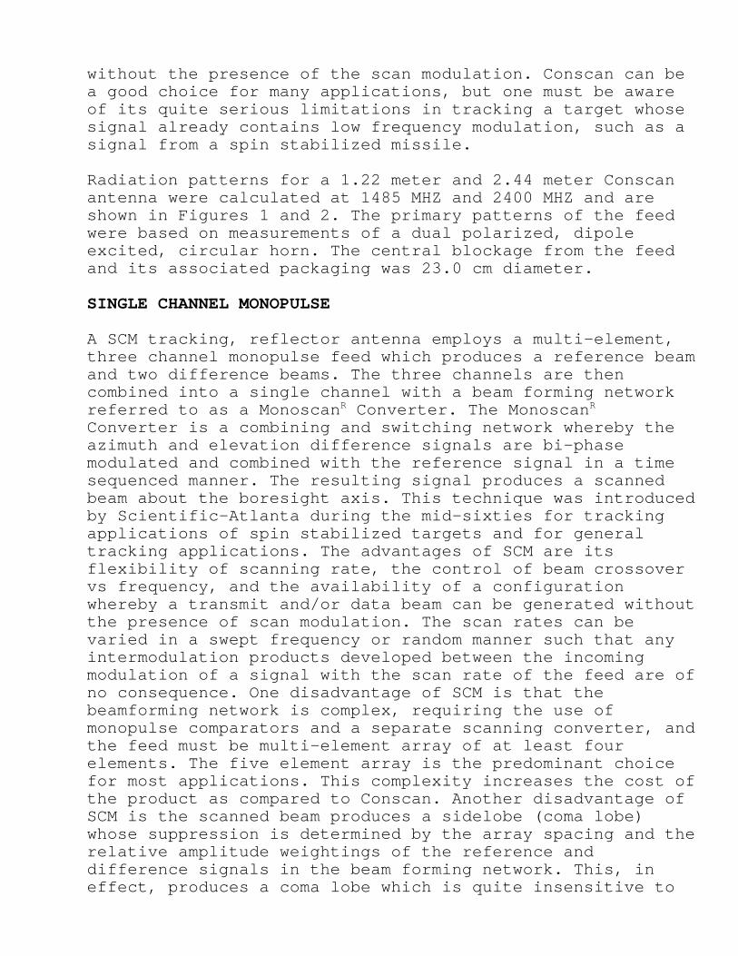
without the presence of the scan modulation. Conscan can bea good choice for many applications, but one must be awareof its quite serious limitations in tracking a target whosesignal already contains low frequency modulation, such as asignal from a spin stabilized missile.
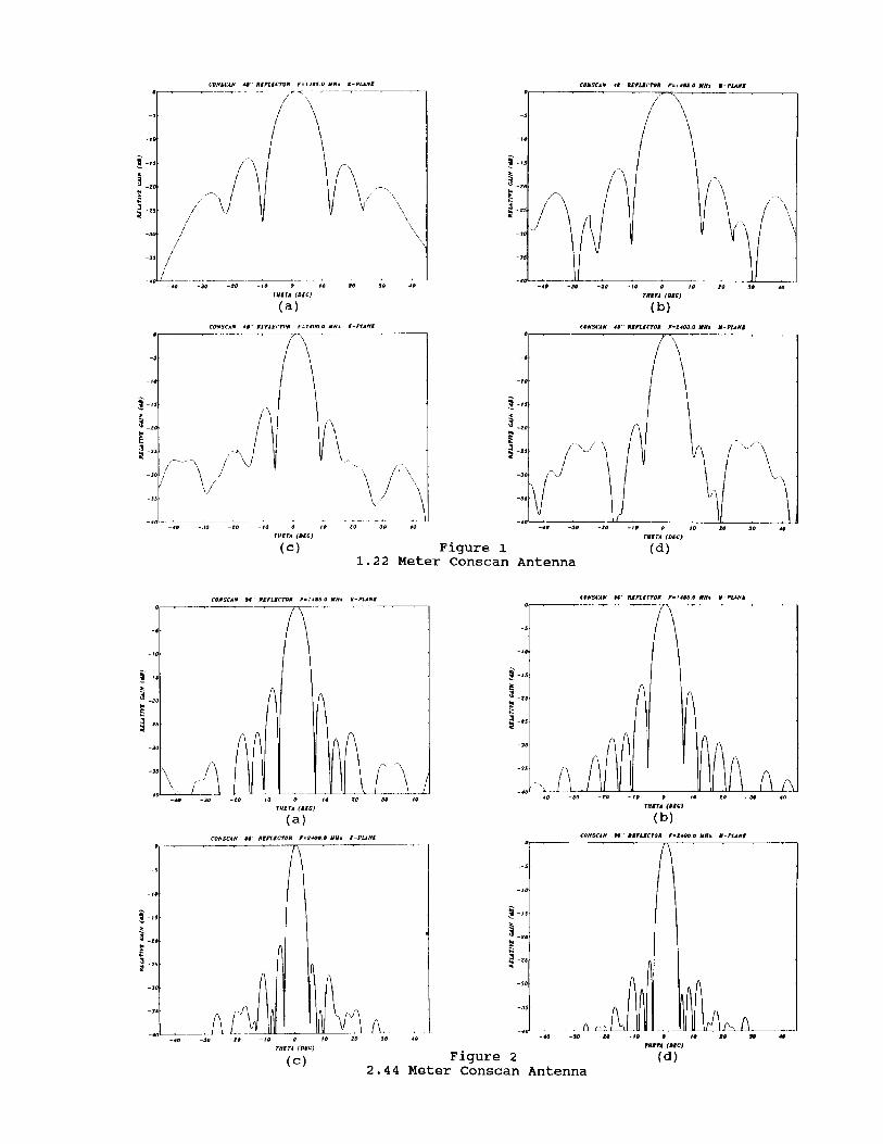
Radiation patterns for a 1.22 meter and 2.44 meter Conscanantenna were calculated at 1485 MHZ and 2400 MHZ and areshown in Figures 1 and 2. The primary patterns of the feedwere based on measurements of a dual polarized, dipoleexcited, circular horn. The central blockage from the feedand its associated packaging was 23.0 cm diameter.
SINGLE CHANNEL MONOPULSE
A SCM tracking, reflector antenna employs a multi-element,three channel monopulse feed which produces a reference beamand two difference beams. The three channels are thencombined into a single channel with a beam forming networkreferred to as a Monoscan Converter. The MonoscanR R
Converter is a combining and switching network whereby theazimuth and elevation difference signals are bi-phasemodulated and combined with the reference signal in a timesequenced manner. The resulting signal produces a scannedbeam about the boresight axis. This technique was introducedby Scientific-Atlanta during the mid-sixties for trackingapplications of spin stabilized targets and for generaltracking applications. The advantages of SCM are itsflexibility of scanning rate, the control of beam crossovervs frequency, and the availability of a configurationwhereby a transmit and/or data beam can be generated withoutthe presence of scan modulation. The scan rates can bevaried in a swept frequency or random manner such that anyintermodulation products developed between the incomingmodulation of a signal with the scan rate of the feed are ofno consequence. One disadvantage of SCM is that thebeamforming network is complex, requiring the use ofmonopulse comparators and a separate scanning converter, andthe feed must be multi-element array of at least fourelements. The five element array is the predominant choicefor most applications. This complexity increases the cost ofthe product as compared to Conscan. Another disadvantage ofSCM is the scanned beam produces a sidelobe (coma lobe)whose suppression is determined by the array spacing and therelative amplitude weightings of the reference anddifference signals in the beam forming network. This, ineffect, produces a coma lobe which is quite insensitive to
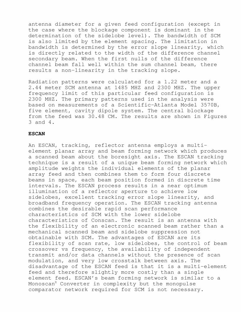
antenna diameter for a given feed configuration (except inthe case where the blockage component is dominant in thedetermination of the sidelobe level). The bandwidth of SCMis also limited by the element spacing. The limitation inbandwidth is determined by the error slope linearity, whichis directly related to the width of the difference channelsecondary beam. When the first nulls of the differencechannel beam fall well within the sum channel beam, thereresults a non-linearity in the tracking slope.
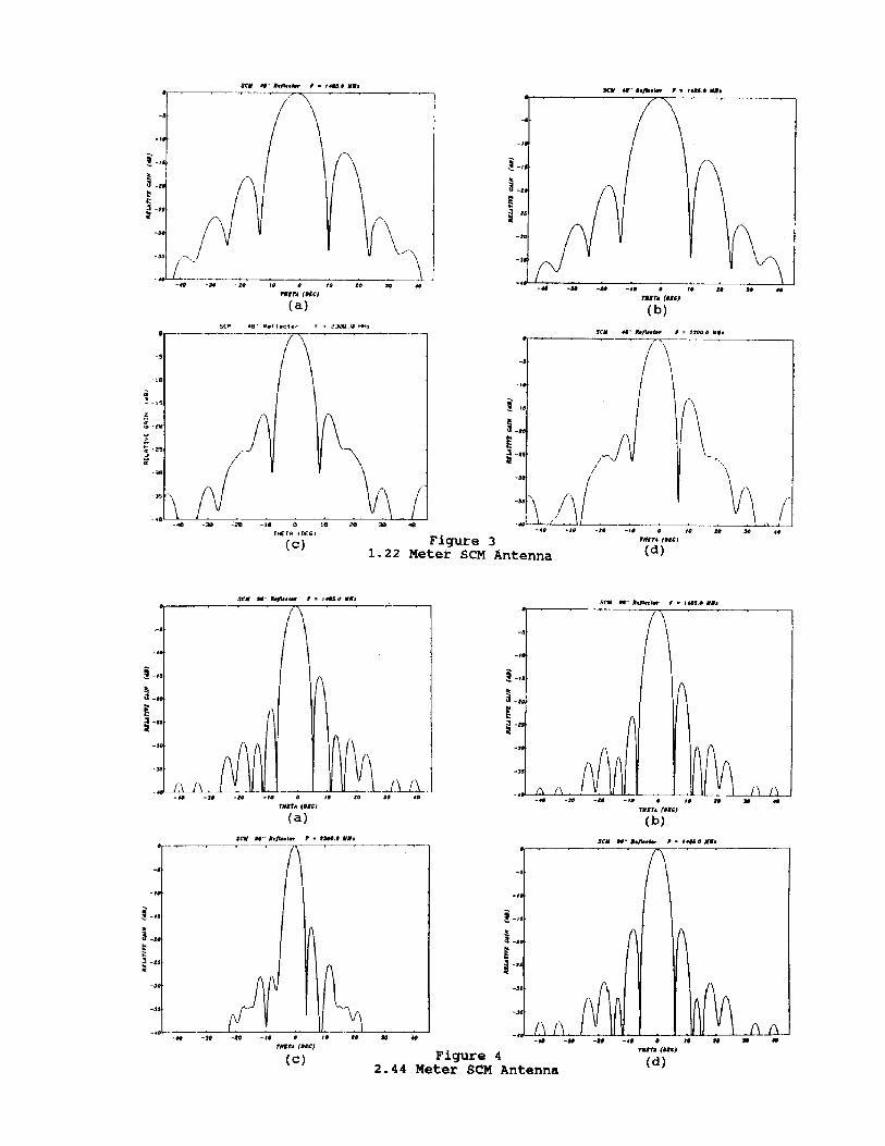
Radiation patterns were calculated for a 1.22 meter and a2.44 meter SCM antenna at 1485 MHZ and 2300 MHZ. The upperfrequency limit of this particular feed configuration is2300 MHZ. The primary patterns used in the analysis werebased on measurements of a Scientific-Atlanta Model 3570B,five element, cavity dipole system. The central blockagefrom the feed was 30.48 CM. The results are shown in Figures3 and 4.
ESCAN
An ESCAN, tracking, reflector antenna employs a multi-element planar array and beam forming network which producesa scanned beam about the boresight axis. The ESCAN trackingtechnique is a result of a unique beam forming network whichamplitude weights the individual elements of the planararray feed and then combines them to form four discretebeams in space, each beam position formed in discrete timeintervals. The ESCAN process results in a near optimumillumination of a reflector aperture to achieve lowsidelobes, excellent tracking error slope linearity, andbroadband frequency operation. The ESCAN tracking antennacombines the desirable rapid scan performancecharacteristics of SCM with the lower sidelobecharacteristics of Conscan. The result is an antenna withthe flexibility of an electronic scanned beam rather than amechanical scanned beam and sidelobe suppression notobtainable with SCM. The advantages of ESCAN are itsflexibility of scan rate, low sidelobes, the control of beamcrossover vs frequency, the availability of independenttransmit and/or data channels without the presence of scanmodulation, and very low crosstalk between axis. Thedisadvantage of the ESCAN feed is that it is a multi-elementfeed and therefore slightly more costly than a singleelement feed. ESCAN’s beam forming network is similar to aMonoscan Converter in complexity but the monopulseR
comparator network required for SCM is not necessary.
The development of a wideband feed for continuous operationfrom 1435 to 2600 MHZ presents several technical challengesfor a multi-element array. The small number of elementsnecessary to minimize the central blockage of the reflectorantenna necessitates the analysis of the feed operationconsider an array of dissimilar sources. An additionalrequirement of the design is for the generation of anon-axis beam for transmitting and for a data channelindependent of the tracking channel. This requirement placedconsiderable restriction on the choice of elements for thearray. The individual element radiation amplitude and phasecharacteristics were measured for the development feed andused in the analysis to predict the secondary radiationpattern performance. The design requirements for the ESCANfeed are given in Table I below.
Table I. Design Requirements for an ESCAN Feed
Frequency 1435 to 2600 MHZVSWR Lin. Pol. 2.0:1 1435 to 1540 MHz
2.5:1 1600 to 1850 MHZ2.0:1 2025 to 2400 MHZ2.25:1 2400 to 2600 MHZ
Cir. Pol. 1.5:1 1435 to 2600 MHZAxial Ratio Lin. Pol. 25 dB minimum
Cir. Pol. 2.0 dB maximumRadiation Pattern Compatible with 0.375 # F/D # 0.5Polarization Dual Linear or Dual Circular, SelectableMaximum Diameter 30.5 cm
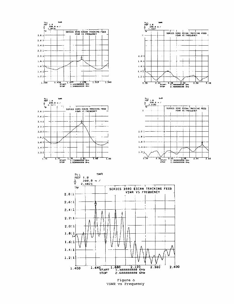
The design requirements were met with a five element array.The feed dimensions are 29.21 cm diameter by approximately30.5 cm in length. The feed housing includes space for anynecessary filters, polarization switching networks,transmit/receive diplexers, and LNAs required for particularmission objectives. The VSWR of the feed is shown inFigure 5.
The antenna efficiency may be determined by an analysis ofthe feed radiation characteristics, the component losses,the diffraction and blockage losses due to the feed and feedsupport, impedance and polarization mismatch losses, and thesurface tolerance of the reflector. The individualefficiency terms are summarized for an independent data andtracking channels in Table II and III for two typicalfrequencies. The 1.22 meter reflector of Table II has a F/Dof 0.5 and the 2.44 meter reflector, of Table III a F/D of
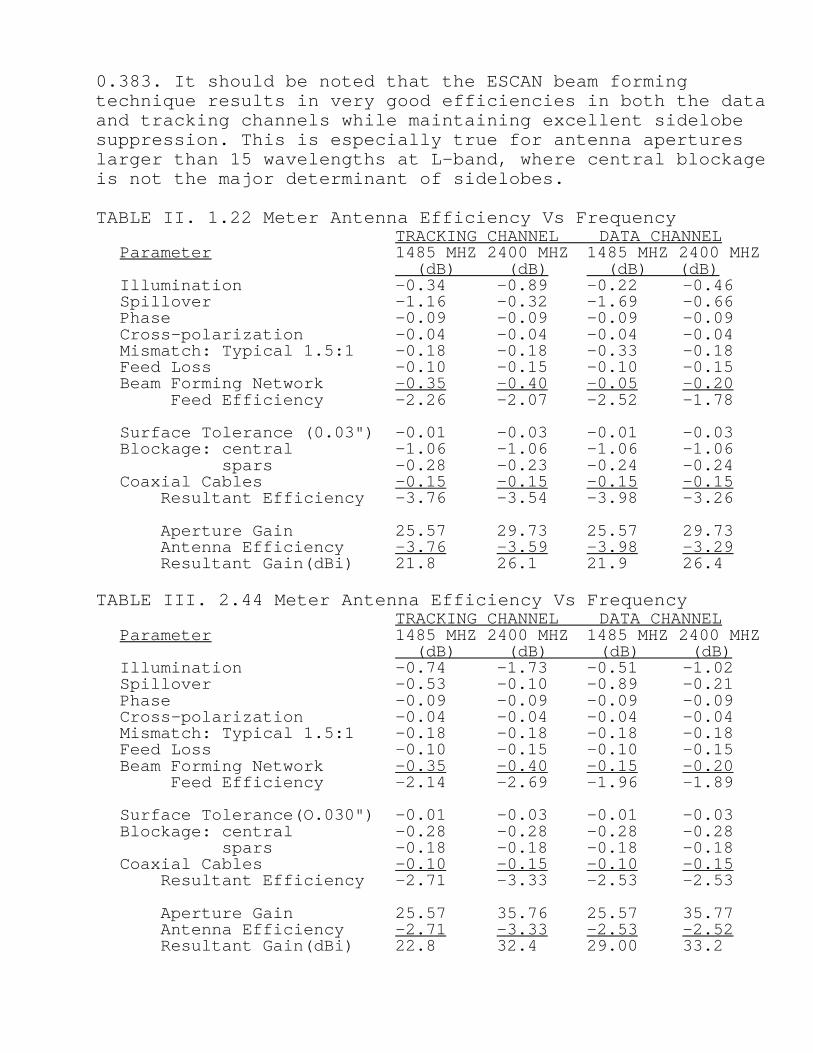
0.383. It should be noted that the ESCAN beam formingtechnique results in very good efficiencies in both the dataand tracking channels while maintaining excellent sidelobesuppression. This is especially true for antenna apertureslarger than 15 wavelengths at L-band, where central blockageis not the major determinant of sidelobes.
TABLE II. 1.22 Meter Antenna Efficiency Vs FrequencyTRACKING CHANNEL DATA CHANNEL
Parameter 1485 MHZ 2400 MHZ 1485 MHZ 2400 MHZ (dB) (dB) (dB) (dB)
Illumination -0.34 -0.89 -0.22 -0.46Spillover -1.16 -0.32 -1.69 -0.66Phase -0.09 -0.09 -0.09 -0.09Cross-polarization -0.04 -0.04 -0.04 -0.04Mismatch: Typical 1.5:1 -0.18 -0.18 -0.33 -0.18Feed Loss -0.10 -0.15 -0.10 -0.15Beam Forming Network -0.35 -0.40 -0.05 -0.20 Feed Efficiency -2.26 -2.07 -2.52 -1.78
Surface Tolerance (0.03") -0.01 -0.03 -0.01 -0.03Blockage: central -1.06 -1.06 -1.06 -1.06 spars -0.28 -0.23 -0.24 -0.24Coaxial Cables -0.15 -0.15 -0.15 -0.15 Resultant Efficiency -3.76 -3.54 -3.98 -3.26
Aperture Gain 25.57 29.73 25.57 29.73 Antenna Efficiency -3.76 -3.59 -3.98 -3.29 Resultant Gain(dBi) 21.8 26.1 21.9 26.4
TABLE III. 2.44 Meter Antenna Efficiency Vs FrequencyTRACKING CHANNEL DATA CHANNEL
Parameter 1485 MHZ 2400 MHZ 1485 MHZ 2400 MHZ (dB) (dB) (dB) (dB)
Illumination -0.74 -1.73 -0.51 -1.02Spillover -0.53 -0.10 -0.89 -0.21Phase -0.09 -0.09 -0.09 -0.09Cross-polarization -0.04 -0.04 -0.04 -0.04Mismatch: Typical 1.5:1 -0.18 -0.18 -0.18 -0.18Feed Loss -0.10 -0.15 -0.10 -0.15Beam Forming Network -0.35 -0.40 -0.15 -0.20 Feed Efficiency -2.14 -2.69 -1.96 -1.89
Surface Tolerance(O.030") -0.01 -0.03 -0.01 -0.03Blockage: central -0.28 -0.28 -0.28 -0.28 spars -0.18 -0.18 -0.18 -0.18Coaxial Cables -0.10 -0.15 -0.10 -0.15 Resultant Efficiency -2.71 -3.33 -2.53 -2.53
Aperture Gain 25.57 35.76 25.57 35.77 Antenna Efficiency -2.71 -3.33 -2.53 -2.52 Resultant Gain(dBi) 22.8 32.4 29.00 33.2
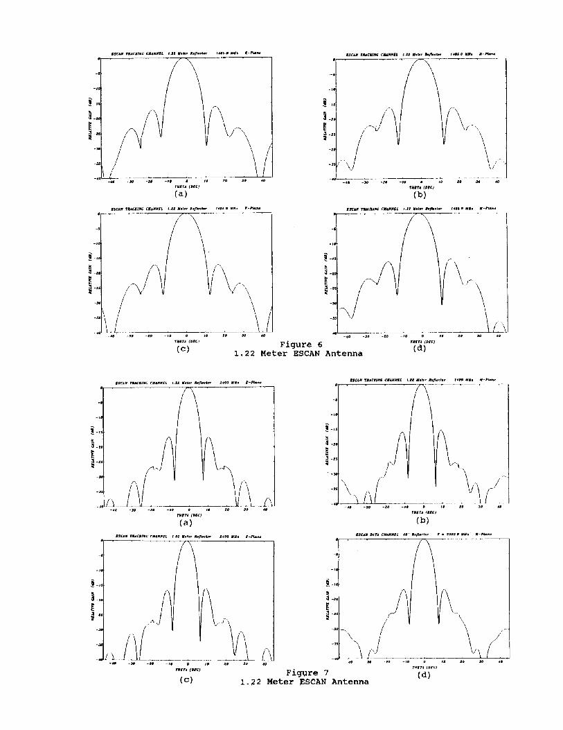
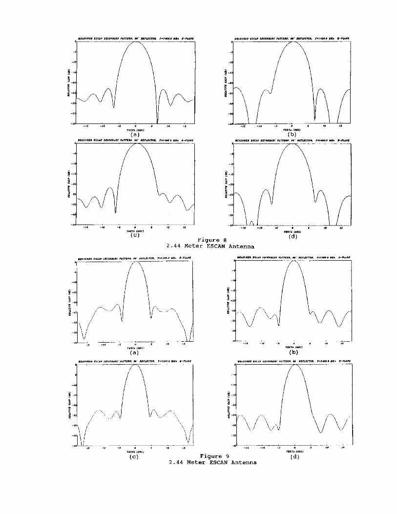
Calculated patterns for a 1.22 meter antenna are shown inFigures 6 and 7 and measured patterns of a 2.44 meterantenna are shown in Figures 8 and 9.
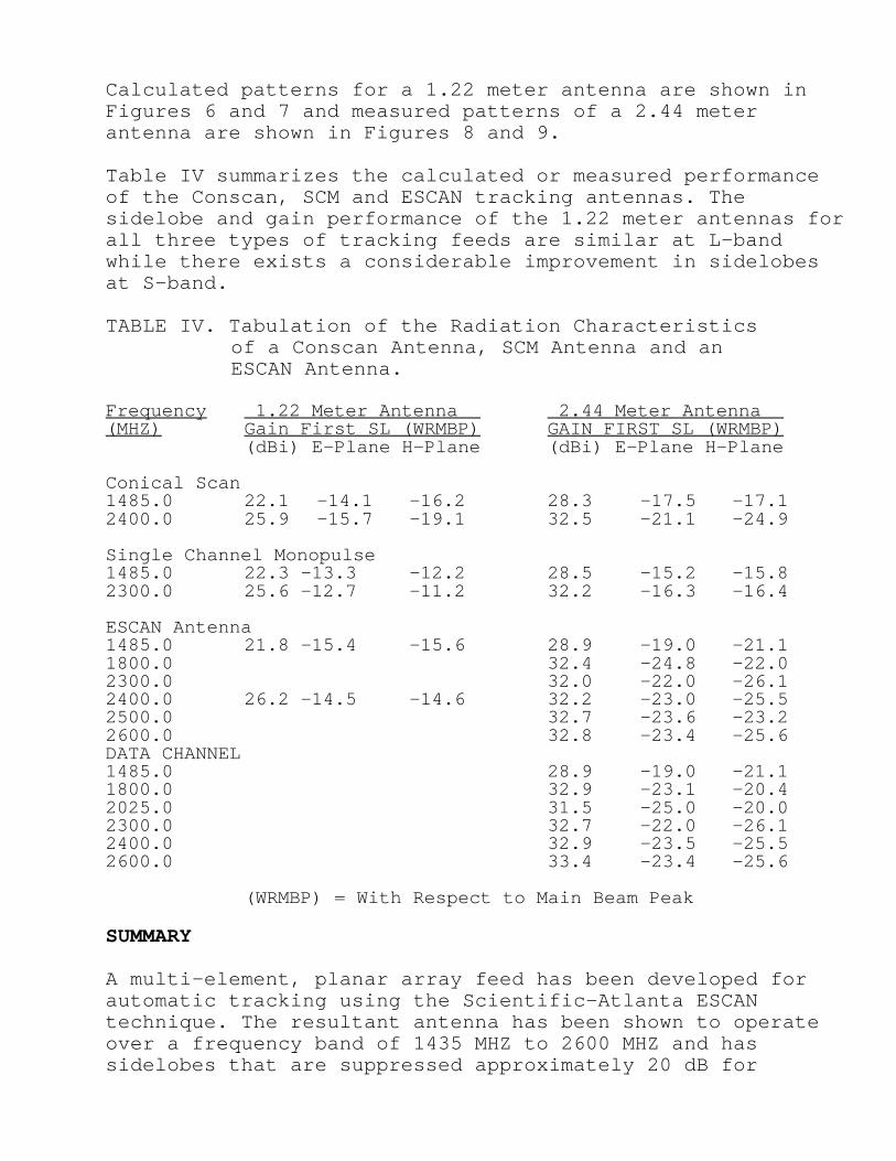
Table IV summarizes the calculated or measured performanceof the Conscan, SCM and ESCAN tracking antennas. Thesidelobe and gain performance of the 1.22 meter antennas forall three types of tracking feeds are similar at L-bandwhile there exists a considerable improvement in sidelobesat S-band.
TABLE IV. Tabulation of the Radiation Characteristicsof a Conscan Antenna, SCM Antenna and anESCAN Antenna.
Frequency 1.22 Meter Antenna 2.44 Meter Antenna (MHZ) Gain First SL (WRMBP) GAIN FIRST SL (WRMBP)
(dBi) E-Plane H-Plane (dBi) E-Plane H-Plane
Conical Scan1485.0 22.1 -14.1 -16.2 28.3 -17.5 -17.12400.0 25.9 -15.7 -19.1 32.5 -21.1 -24.9
Single Channel Monopulse1485.0 22.3 -13.3 -12.2 28.5 -15.2 -15.82300.0 25.6 -12.7 -11.2 32.2 -16.3 -16.4
ESCAN Antenna1485.0 21.8 -15.4 -15.6 28.9 -19.0 -21.11800.0 32.4 -24.8 -22.02300.0 32.0 -22.0 -26.12400.0 26.2 -14.5 -14.6 32.2 -23.0 -25.52500.0 32.7 -23.6 -23.22600.0 32.8 -23.4 -25.6DATA CHANNEL1485.0 28.9 -19.0 -21.11800.0 32.9 -23.1 -20.42025.0 31.5 -25.0 -20.02300.0 32.7 -22.0 -26.12400.0 32.9 -23.5 -25.52600.0 33.4 -23.4 -25.6
(WRMBP) = With Respect to Main Beam Peak
SUMMARY
A multi-element, planar array feed has been developed forautomatic tracking using the Scientific-Atlanta ESCANtechnique. The resultant antenna has been shown to operateover a frequency band of 1435 MHZ to 2600 MHZ and hassidelobes that are suppressed approximately 20 dB for

aperture diameters greater than 15 wavelengths. Sidelobesuppression of approximately 16 dB was demonstrated for anaperture of only six wavelengths at the lowest frequency ofoperation. The ESCAN tracking antenna combines the desirablecharacteristics of SCM, electronic beam scanning and thecapability of configuring a data channel and/or a transmitchannel without the presence of scan modulation, with thesidelobe suppression and gains normally associated withsingle feed aperture designs, such as conscan.
REFERENCE
Cook, J.H. and Dishman, K., “An Improved Scanning1
Automatic, Tracking Antenna for Telemetry Applications”,Proceedings for International Telemetering Conference,Oct. 1989, pp 235-242.