Embed Size (px)
Citation preview
No. i.J NEW ELECTROLYTIC GENERATOR. 6 1
MINOR CONTRIBUTIONS.
A NEW ELECTROLYTIC GENERATOR FOR OXYGEN AND
HYDROGEN.
BY W. S. FRANKLIN.
DURING the year 1895 a preliminary test1 of a generator, of novel design, for the rapid and efficient generation of oxygen and hydro
gen by electrolysis has been carried out in the Physical Laboratory of Iowa Agricultural College. The earlier part of this test brought out, as was to be expected, a number of essential imperfections in the preliminary design, which was accordingly modified, and the apparatus twice reconstructed. The experimental work was unexpectedly cut short in October, 1895,
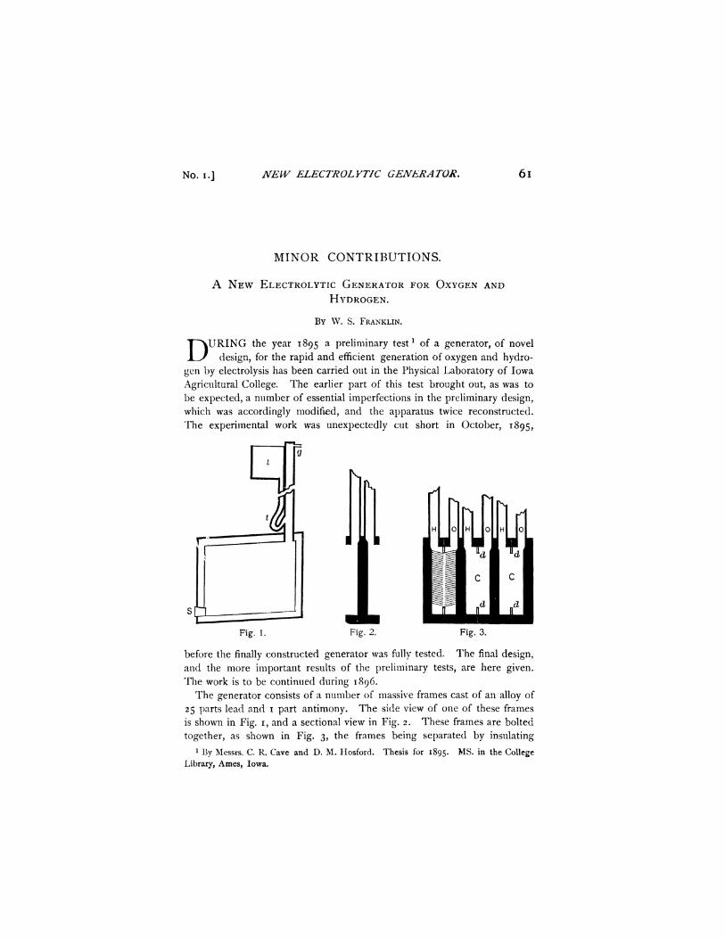
Fig. 1. Fig. 2. Fig. 3.
before the finally constructed generator was fully tested. The final design, and the more important results of the preliminary tests, are here given. The work is to be continued during 1896.
The generator consists of a number of massive frames cast of an alloy of 25 parts lead and 1 part antimony. The side view of one of these frames is shown in Fig. 1, and a sectional view in Fig. 2. These frames are bolted together, as shown in Fig. 3, the frames being separated by insulating
1 By Messrs. C. R. Cave and D. M. Hosford. Thesis for 1895. M $ - in the College Library, Ames, Iowa.
62 W. S. FRANKLIN. [VOL. IV.
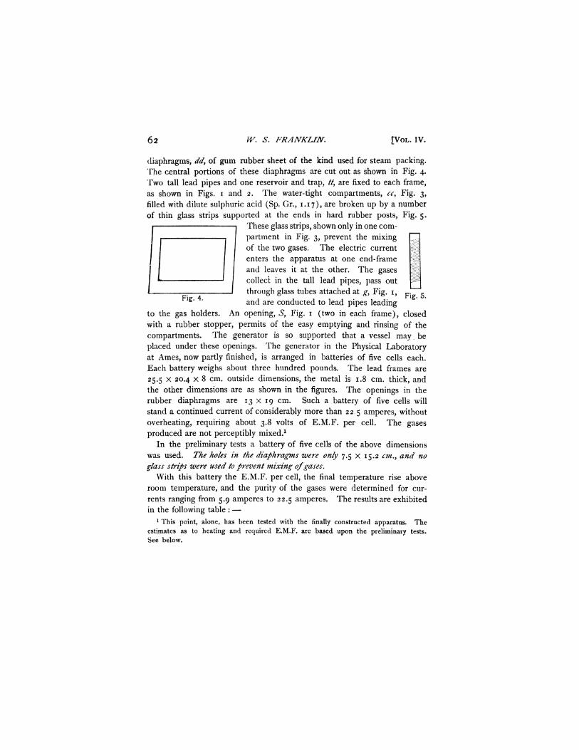
diaphragms, dd, of gum rubber sheet of the kind used for steam packing. The central portions of these diaphragms are cut out as shown in Fig. 4. Two tall lead pipes and one reservoir and trap, //, are fixed to each frame, as shown in Figs. 1 and 2. The water-tight compartments, cc, Fig. 3, filled with dilute sulphuric acid (Sp. Gr., 1.17), are broken up by a number of thin glass strips supported at the ends in hard rubber posts, Fig. 5.
These glass strips, shown only in one compartment in Fig. 3, prevent the mixing of the two gases. The electric current enters the apparatus at one end-frame and leaves it at the other. The gases collect in the tall lead pipes, pass out through glass tubes attached at g, Fig. 1, p! '5
l g ' ' and are conducted to lead pipes leading
to the gas holders. An opening, S, Fig. 1 (two in each frame), closed with a rubber stopper, permits of the easy emptying and rinsing of the compartments. The generator is so supported that a vessel may be placed under these openings. The generator in the Physical Laboratory at Ames, now partly finished, is arranged in batteries of five cells each. Each battery weighs about three hundred pounds. The lead frames are 25.5 x 20.4 x 8 cm. outside dimensions, the metal is 1.8 cm. thick, and the other dimensions are as shown in the figures. The openings in the rubber diaphragms are 13 x 19 cm. Such a battery of five cells will stand a continued current of considerably more than 22 5 amperes, without overheating, requiring about 3.8 volts of E.M.F. per cell. The gases produced are not perceptibly mixed.1
In the preliminary tests a battery of five cells of the above dimensions was used. The holes in the diaphragms were only 7.5 x 15.2 cm., and no glass strips were used to prevent mixing of gases.
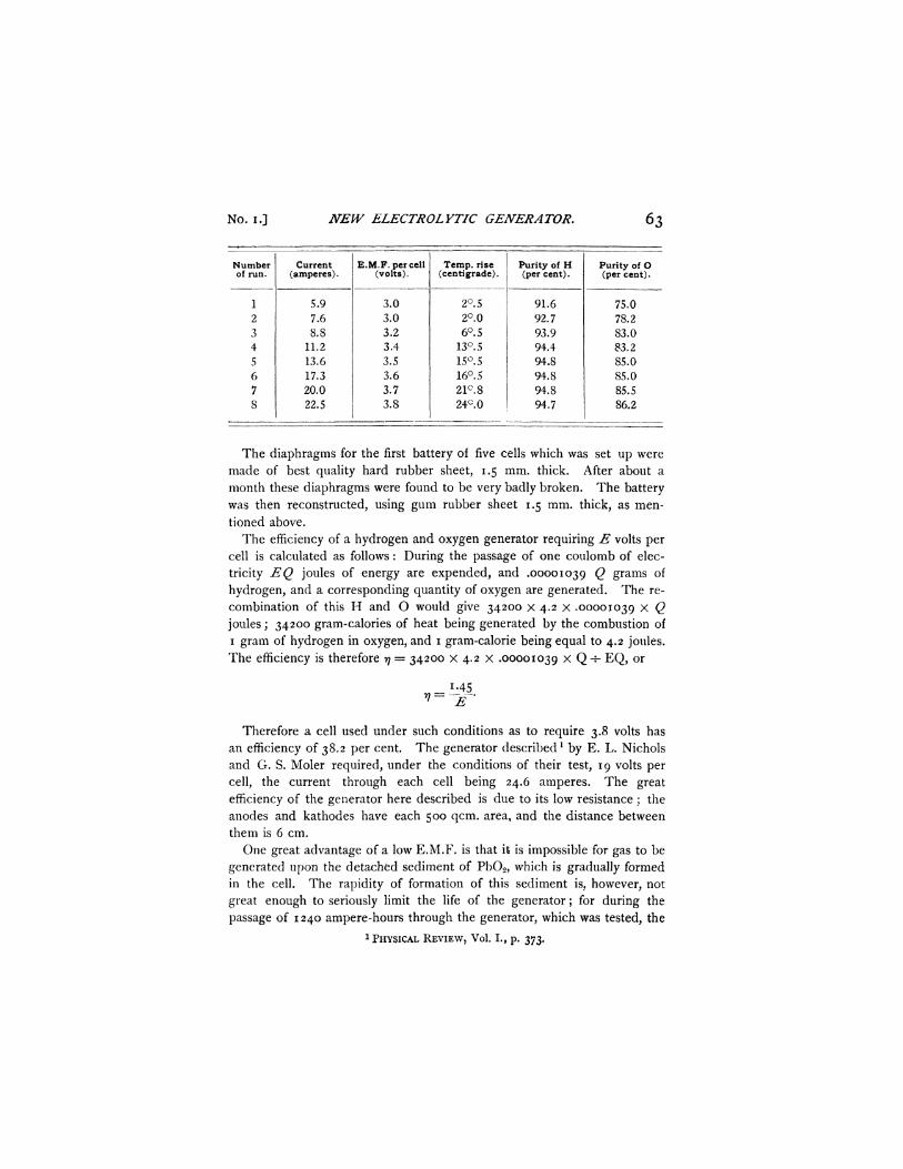
With this battery the E.M.F. per cell, the final temperature rise above room temperature, and the purity of the gases were determined for currents ranging from 5.9 amperes to 22.5 amperes. The results are exhibited in the following table : —
1 This point, alone, has been tested with the finally constructed apparatus. The estimates as to heating and required E.M.F. are based upon the preliminary tests. See below.
No. i J NEW ELECTROLYTIC GENERATOR. 6 3
Number of run.
1 2 3 4 5 6 7 8
Current (amperes).
5.9 7.6 8.8
11.2 13.6 17.3 20.0 22.5
E.M.F. per cell (volts).
3.0 3.0 3.2 3.4 3.5 3.6 3.7 3.8
Temp, rise (centigrade).
2°. 5 2°.0 6°. 5
13°. 5 15°. 5 16°. 5 21c.8 24c.O
Purity of H (per cent).
91.6 92.7 93.9 94.4 94.8 94.8 94.8 94.7
Purity of O (per cent).
75.0 78.2 83.0 83.2 85.0 85.0 85.5 86.2
The diaphragms for the first battery of five cells which was set up were made of best quality hard rubber sheet, 1.5 mm. thick. After about a month these diaphragms were found to be very badly broken. The battery was then reconstructed, using gum rubber sheet 1.5 mm. thick, as mentioned above.
The efficiency of a hydrogen and oxygen generator requiring E volts per cell is calculated as follows : During the passage of one coulomb of electricity EQ joules of energy are expended, and .00001039 Q grams of hydrogen, and a corresponding quantity of oxygen are generated. The recombination of this H and O would give 34200 x 4.2 x .00001039 x Q joules; 34200 gram-calories of heat being generated by the combustion of 1 gram of hydrogen in oxygen, and 1 gram-calorie being equal to 4.2 joules. The efficiency is therefore rj = 34200 x 4.2 x .00001039 x Q ^ EQ, or
Therefore a cell used under such conditions as to require 3.8 volts has an efficiency of 38.2 per cent. The generator describedl by E. L. Nichols and G. S. Moler required, under the conditions of their test, 19 volts per cell, the current through each cell being 24.6 amperes. The great efficiency of the generator here described is due to its low resistance; the anodes and kathodes have each 500 qcm. area, and the distance between them is 6 cm.
One great advantage of a low E.M.F. is that it is impossible for gas to be generated upon the detached sediment of Pb02 , which is gradually formed in the cell. The rapidity of formation of this sediment is, however, not great enough to seriously limit the life of the generator; for during the passage of 1240 ampere-hours through the generator, which was tested, the
1 PHYSICAL REVIEW, Vol. I., p. 373.
6 4 H. 3f. RANDALL AND W. A. MARKEY. [VOL. JV.
amount of Pb0 2 formed was not great enough to be estimated. The test was continued at frequent intervals for more than a month, so that it seems that no serious corrosion of the frames could take place in less than fifteen or twenty years of use.
At 15 cents per kilowatt-hour for electrical energy, 660 liters H and 330 liters O would cost about 80 cents, counting 4 volts per cell of generator. This is sufficient to run a strong lime light for three hours. Counting oxygen only as of value, its cost would be 12.40 per kiloliter (about 8 cents per cubic foot). It seems, therefore, with a generator efficiency of 1.45-1-4 = 36 per cent, that the electrolytic generation of H and O for laboratory purposes is not only the most convenient, but perhaps also the cheapest method of production.
A N A P P A R A T U S FOR ILLUSTRATING T H E L A W S OF F A L L I N G
B O D I E S .
BY II. M. RANDALL AND W. A. MARKEY.
THE problem of uniformly accelerated motion as illustrated by falling bodies has always been a difficult one for laboratory experiment.
The piece of apparatus here described was devised for the purpose of obtaining the necessary data from a practically freely falling body, and is simple both in idea and in manipulation.
The apparatus is shown in the accompanying figure and will be seen to possess considerable stability, the top and the base being of cast iron held rigidly together by three pieces of steel shafting. The failing body is quite heavy, and consists of three iron plates, but one shown in the figure, twenty inches in length, soldered to triangular end pieces. Through the centers of these triangular ends passes the guiding rod AB. One of the faces of the falling body is furnished with a wide rubber band E, which holds in position a strip of stiff paper CD. The body is held in suspension at about the height shown in figure by a thread RS. This thread is so tied to the rod R, which projects from the base of the falling body, that it passes over the forward surface of the paper very near its outer edge. The thread is furnished by the spool G, which can be clamped in any position by the thumb screw on its top.
A heavy brass wheel W is carefully mounted in an iron frame which turns about the shaft as an axis. The wheel is furnished with a knife edge made from a stout knitting needle. This knife K projects about a sixteenth of an inch beyond the circumference of the wheel. The rod M is so clamped to the shafting that it arrests the motion of the iron frame when turned toward the suspended body at such a point that the circum-