Embed Size (px)
Citation preview
DATA PAPER
A New Data Set for Full-Scale ReinforcedConcrete Columns underCollapse-Consistent Loading Protocols
Alireza Nojavan,a) M.EERI, Arturo E. Schultz,a) M.EERI,Curt Haselton,b) M.EERI, Sanput Simathathien,c) Xuejian Liu,c)
and Shih-Ho Chao,c) M.EERI
A series of eight full-scale reinforced concrete column tests was recentlycarried out at the NEES (Network for Earthquake Engineering Simulation)Multi-Axial Subassemblage Testing (MAST) site at the University of Minnesotaas part of a National Science Foundation (NSF) NEES research program. The testswere conducted to address the shortcomings in the available database of reinforcedconcrete (RC) columns tested with large drift ratios under monotonic and cyclicloading protocols. The specimens were designed based on ACI 318-11 andfeatured two different cross-sectional dimensions, both larger than nearly all ofthe columns tested previously. They were subjected to several large displacementloading protocols, including a monotonic and a cyclic biaxial loading protocol.Also, to investigate the effectiveness of novel materials, one specimen was con-structed with ultra-high-performance fiber-reinforced concrete (UHP-FRC). Thispaper presents a description of and potential uses for the data set that is made acces-sible via a digital object identifier (DOI) (data set DOIs: 10.4231/D33T9D65T,10.4231/D3028PD2G, 10.4231/D3V97ZR8Z, 10.4231/D3QN5ZB62, 10.4231/D3KW57J3S, 10.4231/D3G44HQ9B, 10.4231/D3BC3SX4Q, and 10.4231/D36M3340C). [DOI: 10.1193/040314EQS047]
INTRODUCTION
One of the primary goals of conducting tests on RC columns is to enhance knowledge oftheir behavior and to develop component models that can predict the columns’ seismic per-formance in a structural system. For the purpose of seismic performance–based design,improved component models are required to capture the post-peak behavior of columnsmore accurately. Development of such improved models—which is important, accordingto the National Institute of Standards and Technology (NIST) and the National EarthquakeHazards Reduction Program (NEHRP; ACEHR 2008, NIST 2009)—requires that the short-comings in available RC column test data be addressed.
Earthquake Spectra, Volume 31, No. 2, pages 1211–1231, May 2015; © 2015, Earthquake Engineering Research Institute
a) Department of Civil, Environmental and Geo-Engineering, University of Minnesota, Minneapolis, MNb) Department of Civil Engineering, California State University, Chico, CAc) Department of Civil Engineering, University of Texas at Arlington, Arlington, TX
1211

A large number of experimental investigations have been carried out to understand thebehavior of RC columns subjected to various loading protocols. The properties of 326 testson rectangular RC columns are presented by Ghannoum and Sivaramakrishnan (2012).Primary variables in these tests include axial load ratio, lateral loading scheme, cross-sectional dimensions, shear span–to-depth ratio, amount and distribution of transverse rein-forcements, and bond-slip characteristics. Figure 1 illustrates the maximum cross-sectionaldimension, maximum drift ratio, and failure mode of column specimens in previous experi-ments. It shows that columns with flexural failure modes feature a maximum cross-sectionaldimension of 24 in. A few of the smaller specimens were loaded to drift ratios of 10% ormore; columns with larger cross-sectional dimensions were loaded to drift ratios smaller than5% because they failed in more brittle modes, either in shear or in flexure-shear.
There are no data on flexure-dominated column sections of sufficiently large dimensionsto realistically represent those used in the lower stories of multistory buildings and loaded tosufficiently large drifts (∼10%) to elucidate their degradation characteristics for calibration ofcollapse simulation models. Therefore, to investigate the seismic performance of flexure-dominated RC columns and to generate and calibrate component models, especially atthe near-collapse stage, specimens that are representative of those typical in tall buildingsare required to undergo large deformation levels under which they exhibit significant strengthloss (i.e., 80%) and post-peak behavior (i.e., up to residual strengths equal to approximately20% of peak resistance). Several studies have explored the effects of loading protocol on thebehavior of RC members (ATC 2009a, Dhakal and Fenwick 2008, Ingham et al. 2001, Stoneet al. 1995, Takemura and Kawashima 1997). However, in only a limited number of inves-tigations were identical specimens placed under both monotonic and cyclic loading protocols(ATC 2009a, Haselton et al. 2008). Also, in many experiments column specimens were sub-jected to symmetric cyclic reversals of lateral displacements, in addition to either a constant(Lehman and Moehle 1998, Jaradat et al. 1998, Esmaeily-Gh. and Yan 2002) or a variable(Gilbersten and Moehle 1980, Kreger and Linbeck 1986) axial load. However, in an actual
0
2.5
5
7.5
10
12.5
15
0 10 20 30 40
Max
imum
dri
ft (
%)
Maximum cross-sectional dimension (in.)
Flexure
Flexure-shear
Shear
Figure 1. Properties of previous tests on rectangular RC columns.
1212 NOJAVAN ET AL.
earthquake small loading cycles are often followed by large unsymmetric displacementexcursions that can lead to major plastic deformations in one direction and in turn to struc-tural collapse due to P-delta effect. Therefore, it is necessary to investigate the effect ofunsymmetric cyclic loading protocols that represent what columns will experience duringearthquakes.
To address the shortcomings of the available data set for rectangular RC columns, a seriesof eight full-scale columns were subjected to a constant axial load and various loadingschemes, including uniaxial and biaxial symmetric cyclic, near-collapse unsymmetric cyclic,and single-cycle loading protocols. The protocols were designed to attain drift ratios exceed-ing 10% such that the specimens would lose most of their lateral loading capacity and exhibitsignificant loss of flexural strength. The specimens were representative of actual columns inthe ground floor of a 20-story building located in a high seismic region and featuring twodifferent cross-sectional dimensions (36� 28 in: and 28� 28 in:) that are larger than allflexure-critical columns tested previously.
In a related matter, limited investigation was conducted on the helpful effects of ultra-high-performance fiber-reinforced concrete (UHP-FRC) in improving damage tolerancewhen applied in large column specimens. To study the effects of this emerging innovativematerial in enhancing the seismic performance of columns, one of the specimens was con-structed with UHP-FRC consisting of a mixture of high-strength steel microfibers (with acompressive strength of 25 ksi at 28 days).
The experimental data recorded during the eight tests are available through DOI linksprovided in this paper. The DOIs also contain all required pre- and post-test information,including assembly of the specimens, cross-sectional details for each specimen, material prop-erties, location and orientation of the sensors and instrumentations (LVDTs, string pots, tilt-meters, and strain gages), and video and still images for each specimen. The data set isprovided in complete accordance with available databases such as the ACI 369 RectangularColumnDatabase (Ghannoum and Sivaramakrishnan 2012), and the Pacific Earthquake Engi-neeringResearch center (PEER) Structural Database (Berry et al. 2004). The data set describedhere will provide an opportunity for researchers to explore the performance of RC columns invarious cyclic loading conditions. It will also help researchers enhance their knowledge of theseismic performance of full-size columns under severe loading conditions and to employ it todevelop enhanced computational tools and seismic code provisions for structural design.
TEST SETUP
Eight full-scale RC columns with two different cross-sectional dimensions were built andtested under distinct axial load ratios and various lateral loading protocols. All of the speci-mens were constructed and cast in an upright position in the Civil Engineering laboratory ofthe University of Texas at Arlington, Texas, and were tested at the Multi-Axial Subassem-blage Testing (MAST) laboratory of the University of Minnesota. The six-degree-of-freedom(6-DOF) loading system at the MAST lab is capable of applying up to 1,320 kips of verticalforce, 880 kips of lateral force in two orthogonal horizontal directions, 8,910 kip-ft ofmoments, and maximum displacements of �20 in: and �16 in: in the vertical and horizontaldirections, respectively (French et al. 2004, NEES@Minnesota 2014). The loading crossheadof the MAST lab is controlled by an MTS 6-DOF shake-table controller that computes the
ANEWDATA SET FOR FULL-SCALE RC COLUMNS UNDER COLLAPSE-CONSISTENT LOADING PROTOCOLS 1213
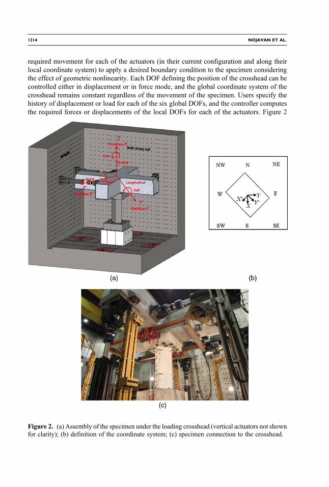
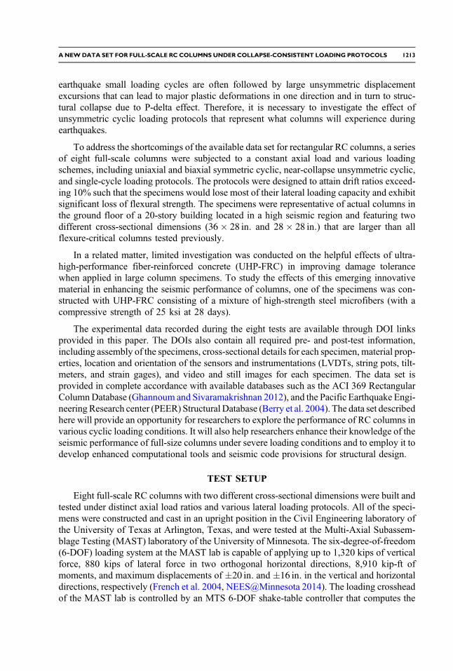
required movement for each of the actuators (in their current configuration and along theirlocal coordinate system) to apply a desired boundary condition to the specimen consideringthe effect of geometric nonlinearity. Each DOF defining the position of the crosshead can becontrolled either in displacement or in force mode, and the global coordinate system of thecrosshead remains constant regardless of the movement of the specimen. Users specify thehistory of displacement or load for each of the six global DOFs, and the controller computesthe required forces or displacements of the local DOFs for each of the actuators. Figure 2
Figure 2. (a) Assembly of the specimen under the loading crosshead (vertical actuators not shownfor clarity); (b) definition of the coordinate system; (c) specimen connection to the crosshead.
1214 NOJAVAN ET AL.

illustrates the assembly of a specimen under the loading crosshead at the MAST lab and thedefinition of the MAST and specimen coordinate systems.
The specimens were oriented at a 45° angle (X 0-Y 0 axes) with respect to the MAST labprimary coordinate system (X-Y axes) to provide a larger stroke capacity of �22.6 in: in thediagonal direction (X 0 or Y 0) for the actuators, as opposed to �16 in: stroke capacity in theX (or Y) direction. The test specimen comprised the lower portion of a column in double cur-vature plus a short segment above the point of inflection such that the latter was located 10 in.below the soffit of the top block of the specimen. To keep the inflection point at the desiredlocation, a flexuralmoment was introduced by the crosshead on top of the specimen (Figure 3).
SPECIMENS
The specimens were representative of the lower portion of a column bent in double cur-vature (Figure 3) at the ground floor of a 20-story prototype moment-resistant frame building.Columns were designed according to seismic provisions in Chapter 21 of ACI 318-11 (ACI2011) and were designated as perimeter frame (PF) or space frame (SF) depending on theirlocation in the floor plan, representing an interior column along the perimeter frame and aninterior column in a space frame, respectively. The PF specimens had a rectangular crosssection of 36� 28 in: with 16 #9 longitudinal bars; the SF specimens featured a 28-in. square
Figure 3. Location of the inflection point and definition of the top moment.
ANEWDATA SET FOR FULL-SCALE RC COLUMNS UNDER COLLAPSE-CONSISTENT LOADING PROTOCOLS 1215

cross section with 12 #8 longitudinal bars (Figure 4). In both specimen types, the longitudinalbars were tied with closed hoops bent from #5 bars and placed with 5- or 6-in. center-to-center spacing depending on their location relative to the column base. The column portion ofall specimens were 106 in. tall and were cast along with an 84� 84� 30-in: footing blockand a 75� 75� 23-in. loading (top) block. The footing block enabled connection to a post-tensioned, three-piece concrete base block of 102� 102� 60-in. dimensions, which itselfwas attached to the lab strong floor using 1.5-in. ASTM A193 Grade-B7 threaded rods with aminimum yield strength of 125 ksi. The loading block connected to the MAST crossheadusing the same threaded rods. The entire testing assembly had a height of 219 in. under thecrosshead. Figure 4 illustrates a typical PF specimen along with cross-sectional details ofboth specimen types.
MATERIALS
The specimens were built using ASTM A706 Grade-60 reinforcing steel and normal-strength, normal-weight concrete except the last specimen (SP8), which was built with
Figure 4. (a) Three-dimensional rendering of PF specimens and (b) cross-sectional detailing ofPF (top) and SF specimens (bottom).
1216 NOJAVAN ET AL.

UHP-FRC. The concrete used for the specimens was self-compacting with a maximumaggregate size of 3∕8 in: and a specified nominal 28-day compressive strength of5,000 psi. The concrete strength of each specimen was determined using standard cylindertests according to ASTM C39C (ASTM 2003a). For each specimen, three 4� 8-in: cylinderswere tested on the day the specimen was tested. The concrete mix design for the columnspecimens is presented in Table 1. Average measured specimen compressive strengths onthe testing day are presented in Table 2. The UHP-FRC specimen was constructed with con-crete with a compressive strength at 28 days of 25 ksi along with a 3% volume fraction ofhigh-strength steel microfibers to improve its ductility and seismic performance.
Uniaxial tensile tests were conducted on steel coupons according to ASTM A370-03a(ASTM 2003b) to measure the mechanical properties of the steel bars. Samples of 18-in.lengths were cut from each heat of reinforcing bars. The samples were instrumented withan 8-in. gage length and pulled at a constant rate of 0.125 in:∕sec. using a 200-kip universaltesting machine with hydraulic grips. In addition to the applied force and displacement,strains were captured by an extensometer located at the middle of the gage length ofeach sample. Mechanical properties of the longitudinal and transverse bars are presentedin Table 2, where b� h show the cross-sectional dimension of each specimen and f y, f u,and εu represent reinforcement yield, ultimate stress, and ultimate strain, respectively.
Table 1. Normal-strength concrete mix design
Weight (lb) for 1 Cu. Yd. normal-strength concrete
Cement Sand
Coarseaggregate(3∕8 in:) Water W/C
Totalweight
748 1,227 1,666 404 0.54 4,045
Table 2. Specimen material properties
Specimenb� h(in.)
f c(psi)
Age oftesting(days)
Longitudinal bars Transverse bars
Barsize
f y(ksi)
f u(ksi) εu
Barsize
f y(ksi)
f u(ksi) εu
SP1 36� 28 4,860 28 9 74 112 0.2 5 69 104 0.12SP2 36� 28 5,400 28 9 74 112 0.2 5 66 108 0.12SP3 36� 28 5,300 28 9 74 112 0.2 5 65 105 0.12SP4 36� 28 5,370 20 9 74 112 0.2 5 65 105 0.12SP5 28� 28 5,270 21 8 59 102 0.15 5 64 103 0.12SP6 36� 28 4,610 19 9 74 112 0.2 5 65 105 0.12SP7 36� 28 4,860 14 9 74 112 0.2 5 62 103 0.11SP8 28� 28 23,000 24 8 59 102 0.15 5 63 104 0.12
ANEWDATA SET FOR FULL-SCALE RC COLUMNS UNDER COLLAPSE-CONSISTENT LOADING PROTOCOLS 1217

INSTRUMENTATION
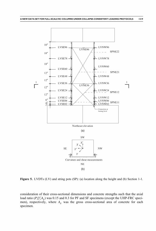
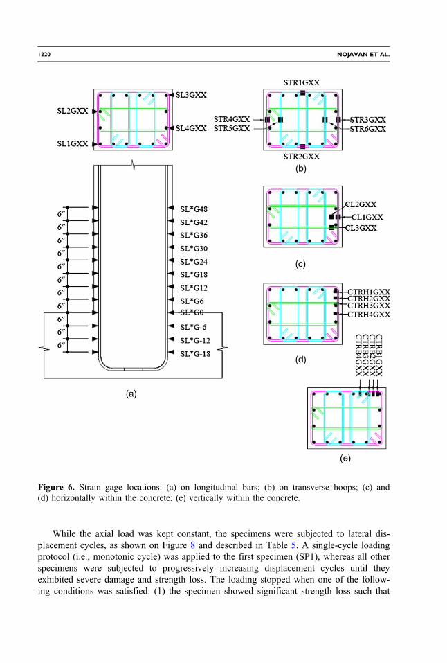
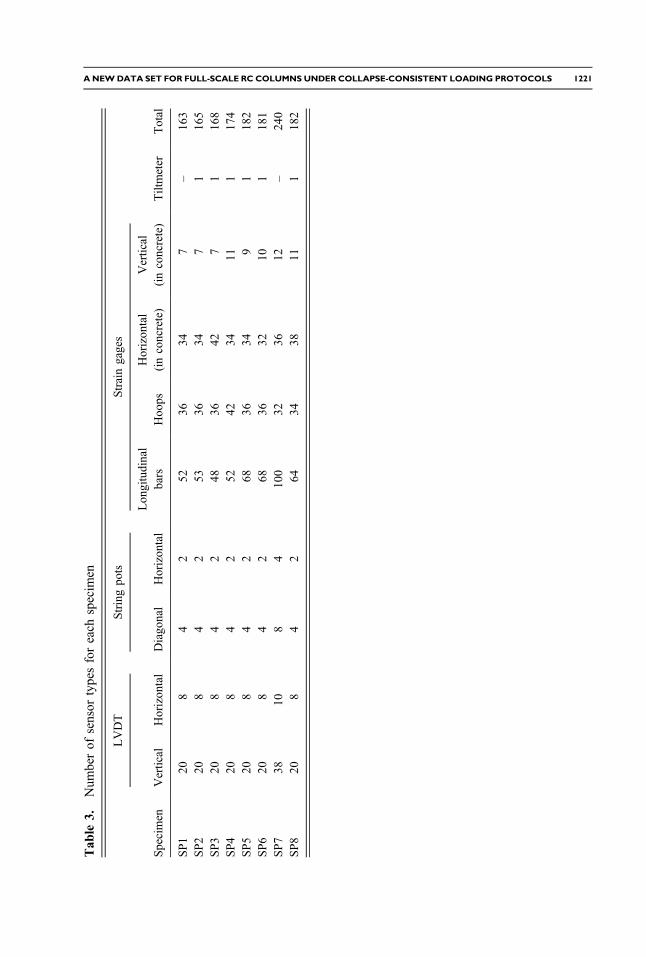
Linear variable differential transformers (LVDTs) were installed in a vertical configura-tion on each specimen to measure column deflections from which curvature could be cal-culated. Also, horizontal LVDTs and diagonal string potentiometers (pots) were installed tomeasure specimen shear deformation at 36 and 96 in. from the column base, as shown inFigure 5. Additional string pots were connected to the specimen at 96 in. from the top of thebase block to track displacement at the inflection point. A tiltmeter was installed at this pointto measure specimen rotations. Strain gages were used to record strains on longitudinal barsand transverse hoops and in the concrete core in each specimen; their location is shown onFigure 6. In the figure, “XX” after the each strain gage name refers to its specific locationalong the specimen height. The total number of different sensor types for each specimen isgiven in Table 3.
Besides the sensors, high- and extra-high-resolution still cameras as well as high-resolution video cameras were applied during each test. Still images were captured byeight Canon SX110IS 9.0-megapixel still-image cameras located at two different elevationson four telepresence towers at the four corners of the MAST strong floor, as shown inFigure 7. Also, high-definition (HD) videos were recorded by eight Sony EVI-HD1 videocameras located next to the image cameras on telepresence towers. Each still camera andvideo recorder was adjusted to focus on a single face of the column specimens. Still imageswere taken either at every 1-in. displacement of the crosshead or at the peak displacement ofeach drift cycle, whereas videos were recorded continuously during the tests. Additionally,three high-resolution cameras, including two Nikon D600 24.3-megapixel digital SLRs and aNikon D3200 24.2-megapixel digital SLR captured high-resolution still images continuouslyduring each test at a rate of one image per 10 s. Moreover, time-lapse images were capturedby a 6-megapixel Canon Powershot Pro Series S3 every 30 s during the test and every 5 minduring specimen preparation.
Table 4 summarizes the amount of visual data (still images and videos) recorded duringeach test. Contact sensors (mini-accelerometers) and air-coupled ultrasonic transmitters wereused on specimens SP6, SP7, and SP8 for nondestructive evaluation (NDE) based on ultra-sonic testing. A nondestructive testing (NDT) technique was conducted on SP6 usingultrasonic shear-wave tomography, known as MIRA, to detect internal defects in thecross section. Discussion of the applied ultrasonic methodology and the results obtainedare discussed elsewhere.
LOADING PROTOCOLS
The RC specimens were subjected to six different loading protocols to investigate theeffect of various seismic loading events. At the beginning of each test, an axial load wasapplied and its magnitude and vertical orientation (i.e., vertical) were kept constant duringthe tests using the eight actuators that drive the MAST crosshead. The movement of eachactuator is computed internally by theMTS controller to ensure the commands defined for theglobal DOFs at the crosshead. Therefore, there is no need for the user to modify the move-ment to account for geometric nonlinearity. The magnitude of the axial load for the speci-mens constructed with normal-weight concrete was selected according to the estimatedstructural demands of the PF and SF columns in the prototype structure and with
1218 NOJAVAN ET AL.
consideration of their cross-sectional dimensions and concrete strengths such that the axialload ratio (P∕f 0cAg) was 0.15 and 0.3 for PF and SF specimens (except the UHP-FRC speci-men), respectively, where Ag was the gross cross-sectional area of concrete for eachspecimen.
12″
12″
12″
12″
18″
18″
LVSE36
LVSE12
LVSE48
LVSE60
LVSE78
LVSE06
Northeast elevation
LVSE96
LVNW36
LVNW12
LVNW48
LVNW60
LVNW78
LVNW06
LVNW96
SPNE22
SPNE21
SPNE12
SPNE11LVSE02 LVNW02
Y′
X′X
Y
SE NW
SW
NE
Curvature and shear measurements
1 1
LVSE24 LVNW24
LVNE36
LVNE96
2″4″6″
10″
Connection atfooting level
(a)
(b)
Figure 5. LVDTs (LV) and string pots (SP): (a) location along the height and (b) Section 1-1.
ANEWDATA SET FOR FULL-SCALE RC COLUMNS UNDER COLLAPSE-CONSISTENT LOADING PROTOCOLS 1219
While the axial load was kept constant, the specimens were subjected to lateral dis-placement cycles, as shown on Figure 8 and described in Table 5. A single-cycle loadingprotocol (i.e., monotonic cycle) was applied to the first specimen (SP1), whereas all otherspecimens were subjected to progressively increasing displacement cycles until theyexhibited severe damage and strength loss. The loading stopped when one of the follow-ing conditions was satisfied: (1) the specimen showed significant strength loss such that
Figure 6. Strain gage locations: (a) on longitudinal bars; (b) on transverse hoops; (c) and(d) horizontally within the concrete; (e) vertically within the concrete.
1220 NOJAVAN ET AL.
Tab
le3.
Num
berof
sensor
typesforeach
specim
en
Specimen
LVDT
Stringpo
tsStraingages
Tiltmeter
Total
Vertical
Horizon
tal
Diago
nal
Horizon
tal
Lon
gitudinal
bars
Hoo
psHorizon
tal
(inconcrete)
Vertical
(inconcrete)
SP1
208
42
5236
347
–16
3SP2
208
42
5336
347
116
5SP3
208
42
4836
427
116
8SP4
208
42
5242
3411
117
4SP5
208
42
6836
349
118
2SP6
208
42
6836
3210
118
1SP7
3810
84
100
3236
12–
240
SP8
208
42
6434
3811
118
2
ANEWDATA SET FOR FULL-SCALE RC COLUMNS UNDER COLLAPSE-CONSISTENT LOADING PROTOCOLS 1221

the residual strengths were less than or equal to 20% of the peak strengths in both direc-tions exhibited during the test; and (2) the hydraulic actuators reached their maximumstroke or rotational capacity.
Except for SP1 and SP6, all other loading protocols were designed in accordance withACI 374-05 guidelines (ACI Committee 374 2005). These protocols comprised three full-reversed displacement cycles at each drift level followed by a small cycle at 1∕3 of the pre-ceding drift level. This loading pattern was applied to SP2, SP5, and SP8 with progressively
Figure 7. Location of the telepresence towers and high-resolution cameras at the MAST lab.
Table 4. Image and video data recorded during each test (GB)
SpecimenStill and
time-lapse imagesExtra-high-
resolution imagesTotalimages Videos
Total imagesand videos
SP1 7.7 75.4 83.1 33.97 117.0SP2 6.7 286.1 292.8 24.1 316.9SP3 8.1 112 120.1 16.9 137.0SP4 7.8 128.7 136.5 17.3 153.8SP5 6.2 106.2 112.4 15.8 128.2SP6 4.4 41.3 45.7 10.0 55.7SP7 10.2 200.9 211.1 41.5 252.6SP8 7.7 153.8 161.5 30.7 192.2
1222 NOJAVAN ET AL.

increasing drift cycles until one of the stopping criteria was satisfied; SP3 and SP4 experi-enced a monotonic push after a certain number of cycles. Displacement cycles were appliedalong the primary axis of the specimens (Y 0 axis in Figure 2b), except for SP7, which wassubjected to a biaxial loading protocol as shown on Figure 8f.
–12
–8
–4
0
4
8
12
0 1 2 3Dri
ft (
%)
Cycle
(a) (b) (c)
(d) (e) (f)
–12
–8
–4
0
4
8
12
0 15 30 45 60Dri
ft (
%)
Cycle–12
–8
–4
0
4
8
12
0 15 30 45 60Dri
ft (
%)
Cycle
–12
–8
–4
0
4
8
12
0 15 30 45 60Dri
ft (
%)
Cycle–12
–8
–4
0
4
8
12
0 2 4 6 8 10Dri
ft (
%)
Cycle –6
–4.5
–3
-1.5
0
1.5
3
4.5
6
–6 –4.5 –3 –1.5 0 1.5 3 4.5 6
Dri
ftY
' (%
)
DriftX′ (%)
Figure 8. Loading protocols for specimens: (a) single-cycle (SP1); (b) ACI 374 symmetric cyclic(SP2, SP5, and SP8); (c) ACI 374 symmetric cyclic followed by final monotonic push #1 (SP3);(d) ACI 374 symmetric cyclic followed by final monotonic push #2 (SP4); (e) near-collapse(SP6); (f) biaxial (SP7).
Table 5. Applied loading protocols
Specimen Typeb� h(in.) P∕f cAg
Loading protocol(see Figure 8) Description of loading protocol
SP1 PF 36� 28 0.154 (a) MonotonicSP2 PF 36� 28 0.139 (b) Symmetric cyclic (ACI 374)SP3 PF 36� 28 0.141 (c) Symmetric cyclic (ACI 374) plus monotonic
pushSP4 PF 36� 28 0.140 (d) Symmetric cyclic (ACI 374) plus monotonic
pushSP5 SF 28� 28 0.285 (b) Symmetric cyclic (ACI 374)SP6 PF 36� 28 0.163 (e) Near-collapseSP7 PF 36� 28 0.154 (f) BiaxialSP8 SF 28� 28 0.065 (b) Symmetric cyclic (ACI 374)
ANEWDATA SET FOR FULL-SCALE RC COLUMNS UNDER COLLAPSE-CONSISTENT LOADING PROTOCOLS 1223
SP6 was subjected to a near-collapse loading protocol that was developed using resultsfrom time-history analysis of a series of low- to high-rise buildings subjected to a set of far-field earthquake records. The near-collapse loading protocol consisted of symmetric cyclesfollowed by large unsymmetric displacement cycles under which typical columns in the timehistory analysis showed significant yielding and strength loss.
TEST OBSERVATIONS
Figure 9 shows specimen damage initiated after application of early cycles when flexuralcracks were observed on the SE and NW faces close to the column base. Also, shear-flexurecracks were observed on the SW and NE faces and distributed through the lower portion of thespecimens. Cracking and spalling of the cover concrete was followed by yielding of the long-itudinal bars. However, the specimens reached their peak strengths at larger displacementlevels because of the resistance mobilized by the confining pressure of the transversehoops aswell as strain hardeningof the longitudinal bars.Cracking and crushingof the concretealong the column perimeters and, more importantly, buckling and fracture of the longitudinalbars resulted in the loss of flexural resistance. In some specimens, spalling of the cover concreteand lateral pressure of the longitudinal bars caused some hoops to open. Buckled bars werefractured at larger drift ratios, which resulted in sudden decreases in lateral load capacity.At theend of the tests, severe damage to the perimeter concrete and fracture of the longitudinal bars inthe extreme faces were observed.
Figure 10 shows applied lateral loads for SP1, SP2, and SP3 plotted against their lateraldrifts (measured at the idealized inflection point) and lateral displacements. The specimenssubjected to these loading protocols [(a), (b), and (c)] were selected as representative of allloading protocols because they included a single cycle, a series of gradually increasing cyclegroups, and a series of gradually increasing cycle groups followed by a collapse-level driftcycle. The loading protocols addressed one of the primary goals of this project: testing RCcolumns under large drift ratios and capturing their post-peak performance at the near-collapsestate. In the first specimen (SP1), the loading was terminated at an approximate 12% drift ratiowhen the actuators reached their rotational capacity. However, the progression of damage andstrength loss in SP2 and SP3 occurred at a greater rate such that the capacity of these speci-mens deteriorated to 20% or less of their peak strength at smaller drift ratios than that of SP1.
Strains in longitudinal bars, transverse hoops, and the concrete core were recorded duringeach test using embedded strain gages, as shown in Figure 6. On longitudinal bars, the straingages were installed at closely spaced points along the lower portion of the column and in thefooting block, by which the onset of yielding, strain hardening, and fracture of longitudinalbars could be identified during application of the loading protocols. As shown in Figure 11a,at a 2.15% drift ratio for specimen SP2, yielding occurred over a large portion of one of thelongitudinal bars. Nominal yielding in Figure 11 can be recognized as a strain equal to0.0025 in:∕in:, as indicated by the dashed line. Also, at the same drift level transversehoops started to yield at a location approximately 12 in. above the column base, asshown in Figure 11b. On transverse hoops, strain gages were installed along the columnheight and at different locations in the cross section (Figure 6).
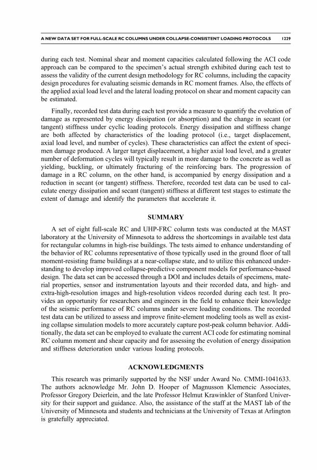
Besides longitudinal bars and transverse hoops, strains at different locations in the con-crete core were measured using vertical and horizontal strain gages. Figures 12a and 12b
1224 NOJAVAN ET AL.

show strain profiles measured along the height of SP2 and at a 2.15% drift ratio. In thesefigures, CL1G corresponds to the vertical strain gage located at the midpoint of the speci-men’s SE face; CTRH4G measures the horizontal strains (as shown on Figure 6). Horizontalstrains measured by CRTH4G fell beyond the cracking strains for the concrete, which wasconfirmed by the formation of several horizontal flexural cracks as observed in Figure 9.
Figure 9. Progression of damage on SP2: (a) SE face at 2.2% drift ratio; (b) SW face at 2.2% driftratio; (c) SE face at the end of the test; (d) SW face at the end of the test.
ANEWDATA SET FOR FULL-SCALE RC COLUMNS UNDER COLLAPSE-CONSISTENT LOADING PROTOCOLS 1225

Along with strain gages, vertical LVDTs were installed on the specimens’ SE and NWfaces (Figure 5) to estimate flexural curvature along the column height. Such estimation wascarried out for the lower portion of specimen SP2, as shown in Figure 13, which illustratesbase moment for specimen SP2 against curvature measured 6 in. above the column base.Curvature at this point was calculated using measurements for the vertical LVDTs on thecolumn’s SE and NW faces. Also, the base moment included the first-order moment causedby application of the lateral load over the column height as well as the second-order momentresulting from the P-delta effect. The LVDT cores were connected to aluminum plateslocated on the footing block. These plates were anchored at a distance from the columnso that they would not get loose after cracking of the concrete at the column base.
FUTURE USE OF THE DATA SET
Recorded data from eight full-scale column tests are available at NEEShub (NEES 2009)for researchers and structural engineers to investigate the observed behavior of the columnspecimens during the tests. These data include measurements from the MAST lab 6-DOF
–12 –8 –4 0 4 8 12
–300
–200
–100
0
100
200
300
Drift (%)
(a) (b)
(c)
Late
ral f
orce
(ki
p)
–16 –12 –8 –4 0 4 8 12 16
Lateral displacement (in.)
SP1
–8 –4 0 4 8
–300
–200
–100
0
100
200
300
Drift (%)
Late
ral f
orce
(ki
p)
–12 –8 –4 0 4 8 12
Lateral displacement (in.)
SP2
–12 –8 –4 0 4 8 12
–300
–200
–100
0
100
200
300
Drift (%)
Late
ral f
orce
(ki
p)
–16 –12 –8 –4 0 4 8 12 16
Lateral displacement (in.)
SP3
Figure 10. Applied load versus crosshead displacement and drift ratio at the inflection point:(a) SP1; (b) SP2; (c) SP3.
1226 NOJAVAN ET AL.
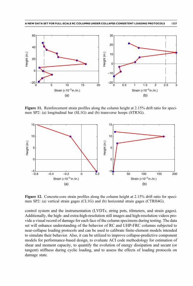
control system and the instrumentation (LVDTs, string pots, tiltmeters, and strain gages).Additionally, the high- and extra-high-resolution still images and high-resolution videos pro-vide a visual record of damage for each face of the column specimens during testing. The dataset will enhance understanding of the behavior of RC and UHP-FRC columns subjected tonear-collapse loading protocols and can be used to calibrate finite-element models intendedto simulate their behavior. Also, it can be utilized to improve collapse-predictive componentmodels for performance-based design, to evaluate ACI code methodology for estimation ofshear and moment capacity, to quantify the evolution of energy dissipation and secant (ortangent) stiffness during cyclic loading, and to assess the effects of loading protocols ondamage state.
(a) (b)
0 5 10 15 20–20
0
20
40
60
Strain ( 10–3 in./in.)
Hei
ght (
in.)
0 0.5 1 1.5 2 2.5 3–20
–10
0
10
20
30
Strain ( 10×× –3 in./in.)
Hei
ght (
in.)
Figure 11. Reinforcement strain profiles along the column height at 2.15% drift ratio for speci-men SP2: (a) longitudinal bar (SL1G) and (b) transverse hoops (STR3G).
(a) (b)
–0.6 –0.4 –0.2 0 0.2–5
0
5
10
15
Strain ( 10× ×–3 in./in.)
Hei
ght (
in.)
0 50 100 150 200–5
0
5
10
15
Strain ( 10–3 in./in.)
Hei
ght (
in.)
Figure 12. Concrete-core strain profiles along the column height at 2.15% drift ratio for speci-men SP2: (a) vertical strain gages (CL1G) and (b) horizontal strain gages (CTRH4G).
ANEWDATA SET FOR FULL-SCALE RC COLUMNS UNDER COLLAPSE-CONSISTENT LOADING PROTOCOLS 1227

First, the test data from this experimental program can enhance knowledge of the beha-vior of RC and UHP-FRC columns subjected to large seismic events, and they can be used toassess and improve finite-element modeling. Previous experiments on RC columns wereperformed either on small- or medium-scale specimens or under small drift ratios. Accord-ingly, finite-element models were typically calibrated with test results that did not capture thecomplete range of column post-peak behavior. The loading protocols in this experimentalprogram were extended to large drift ratios (∼12%) until the specimens exhibited significantstrength loss (i.e., 80% or more of their maximum strength in each loading direction) andstiffness deterioration. The data from this research program will enable finite-element modelcalibration and validation against a wide range of structural performance. Developed modelscan then be utilized to assess the seismic performance of structures under various axial loadratios, cross-sectional dimensions, and loading protocols. Also, the tests performed oncolumns constructed with UHP-FRC material will enhance knowledge of the seismicperformance and damage tolerance capabilities of columns constructed with this innovativematerial, and they will provide a tool to improve structural models that capture theirbehavior.
An important application of the recorded test data is the assessment and improvement ofexisting collapse-predictive component models in performance-based seismic design. A setof comprehensive test data is required for the development of representative nonlinear mod-els and implementation of a reliable analysis for performance-based design. Improved com-ponent models represent an important step in predicting the collapse safety of existingbuildings that are designed in accordance with modern codes as well as in designing reliablestructures. They have been recognized as a requirement for the advancement of performance-based seismic engineering procedures (ATC 2009b). The tests conducted in this researchwere designed considering the critical need for collapse prediction in performance-baseddesign procedures.
The proposed methodology in the ACI code for estimation of column shear and momentcapacity can be evaluated using flexural moments, axial loads, and internal strains measured
–6,000 –4,000 –2,000 0 2,000 4,000 6,000–3,000
–2,000
–1,000
0
1,000
2,000
3,000
Φ (×10–6/in.)
MB
ase (
kip-
ft)
Figure 13. Moment versus curvature relation for SP2 measured 6 in. from the column base.
1228 NOJAVAN ET AL.
during each test. Nominal shear and moment capacities calculated following the ACI codeapproach can be compared to the specimen’s actual strength exhibited during each test toassess the validity of the current design methodology for RC columns, including the capacitydesign procedures for evaluating seismic demands in RC moment frames. Also, the effects ofthe applied axial load level and the lateral loading protocol on shear and moment capacity canbe estimated.
Finally, recorded test data during each test provide a measure to quantify the evolution ofdamage as represented by energy dissipation (or absorption) and the change in secant (ortangent) stiffness under cyclic loading protocols. Energy dissipation and stiffness changeare both affected by characteristics of the loading protocol (i.e., target displacement,axial load level, and number of cycles). These characteristics can affect the extent of speci-men damage produced. A larger target displacement, a higher axial load level, and a greaternumber of deformation cycles will typically result in more damage to the concrete as well asyielding, buckling, or ultimately fracturing of the reinforcing bars. The progression ofdamage in a RC column, on the other hand, is accompanied by energy dissipation and areduction in secant (or tangent) stiffness. Therefore, recorded test data can be used to cal-culate energy dissipation and secant (tangent) stiffness at different test stages to estimate theextent of damage and identify the parameters that accelerate it.
SUMMARY
A set of eight full-scale RC and UHP-FRC column tests was conducted at the MASTlaboratory at the University of Minnesota to address the shortcomings in available test datafor rectangular columns in high-rise buildings. The tests aimed to enhance understanding ofthe behavior of RC columns representative of those typically used in the ground floor of tallmoment-resisting frame buildings at a near-collapse state, and to utilize this enhanced under-standing to develop improved collapse-predictive component models for performance-baseddesign. The data set can be accessed through a DOI and includes details of specimens, mate-rial properties, sensor and instrumentation layouts and their recorded data, and high- andextra-high-resolution images and high-resolution videos recorded during each test. It pro-vides an opportunity for researchers and engineers in the field to enhance their knowledgeof the seismic performance of RC columns under severe loading conditions. The recordedtest data can be utilized to assess and improve finite-element modeling tools as well as exist-ing collapse simulation models to more accurately capture post-peak column behavior. Addi-tionally, the data set can be employed to evaluate the current ACI code for estimating nominalRC column moment and shear capacity and for assessing the evolution of energy dissipationand stiffness deterioration under various loading protocols.
ACKNOWLEDGMENTS
This research was primarily supported by the NSF under Award No. CMMI-1041633.The authors acknowledge Mr. John D. Hooper of Magnusson Klemencic Associates,Professor Gregory Deierlein, and the late Professor Helmut Krawinkler of Stanford Univer-sity for their support and guidance. Also, the assistance of the staff at the MAST lab of theUniversity of Minnesota and students and technicians at the University of Texas at Arlingtonis gratefully appreciated.
ANEWDATA SET FOR FULL-SCALE RC COLUMNS UNDER COLLAPSE-CONSISTENT LOADING PROTOCOLS 1229

REFERENCES
Advisory Committee on Earthquake Hazards Reduction (ACEHR), 2008. Effectiveness of theNational Earthquake Hazards Reduction Program, a Report from the Advisory Committeeon Earthquake Hazards Reduction, Washington, D.C.
American Concrete Institute (ACI) Committee 374, 2005. Acceptance Criteria for MomentFrames Based on Structural Testing and Commentary, ACI 374.1-05, Farmington Hills, MI.
American Concrete Institute (ACI) Committee 318, 2011. Building Code Requirements forStructural Concrete (318-11) and Commentary, Farmington Hills, MI.
American Society for Testing and Materials (ASTM), 2003a. Standard Test Method forCompressive Strength of Cylindrical Concrete Specimens, ASTM C 39C/C39M, WestConshohocken, PA.
American Society for Testing and Materials (ASTM), 2003b. Standard Test Methods andDefinitions for Mechanical Testing of Steel Products, ASTM A 370-03a, West Conshohocken,PA.
Applied Technology Council, 2009a. Effects of Strength and Stiffness Degradation of SeismicResponse, FEMA P440A, Federal Emergency Management Agency (FEMA), Washington,D.C.
Applied Technology Council, 2009b. Qualification of Building Seismic Performance Factors,FEMA P695, Federal Emergency Management Agency (FEMA), Washington, D.C.
Berry, M., Parrish, M., and Eberhard, M., 2004. PEER Structural Performance DatabaseUser’s Manual, Pacific Engineering Research Center (PEER), University of California,Berkeley, CA.
Dhakal, R. P., and Fenwick, R. C., 2008. Detailing of plastic hinges in seismic design of concretestructures, ACI Structural Journal 105, 740–749.
Esmaeily-Gh., A., and Yan, X., 2002. Seismic Behavior of Bridge Columns Subjected to VariousLoading Patterns, PEER Report 2002/15, Pacific Engineering Research Center (PEER),University of California, Berkeley, CA.
French, C. W., Schultz, A. E., Hajjar, J. F., Shield, C. K., Ernie, D. W., Dexter, R. J., Du, D. H. C.,Olson, S. A., Daugherty, D. J., and Wan, C. P., 2004. Multi-axial subassemblagetesting (MAST) system: Description and capabilities, Paper No. 2146, in Proceedings,13th World Conference on Earthquake Engineering, 1–6 August 2004, Vancouver, BritishColumbia.
George E. Brown, Jr., Network for Earthquake Engineering Simulation (NEES) 2009. Web pagefor NEEShub, available at nees.org (last accessed 17 March 2015).
Ghannoum, W., Sivaramakrishnan, B., Pujol, S., Catlin, A. C., Sumudinie, F., Yoosuf, N., andWang, Y., 2012. ACI 369 Rectangular Column Database, Network for Earthquake Engineer-ing Simulation, DOI: 10.4231/D36688J50.
Gilbersten, N. D., and Moehle, J. P., 1980. Experimental Study of Small-Scale R/C ColumnsSubjected to Axial and Shear Force Reversal, Structural Research Series No. 481, Civil Engi-neering Studies, University of Illinois, Urbana-Champaign.
Haselton, C. B., Liel, A. B., Taylor Lange, S., and Deierlein, G. G., 2008. Beam-Column ElementModel Calibrated for Predicting Flexural Response Leading to Global Collapse of RC FrameBuildings, PEER Report 2007/03, Pacific Engineering Research Center (PEER), University ofCalifornia, Berkeley, CA.
1230 NOJAVAN ET AL.
Ingham, J. M., Lidell, D., and Davidson, B. J., 2001. Influence of loading history on the responseof a reinforced concrete beam, Bulletin of the New Zealand Society for Earthquake Engineer-ing 34, 107–124.
Jaradat, O. A., McLean, D. I., and Marsh, M. L., 1998. Performance of existing bridge columnsunder cyclic loading—Part I: Experimental results and observed behavior, ACI StructuralJournal 95 695–704.
Kreger, M. E., and Linbeck, L., 1986. Behavior of reinforced concrete columns subjected tolateral and axial load reversals, in Proceedings, 3rd U.S. National Conference on EarthquakeEngineering, August 1986, Vol. II, Charleston, SC, 1475–1486.
Lehman, D. E., and Moehle, J. P., 1998. Influence of longitudinal reinforcement ratio on columnresponse, Eleventh European Earthquake Engineering Conference, September, Paris, France.
National Institute of Standards and Technology (NIST), 2009. Research Required to Support FullImplementation of Performance-Based Seismic Design, NIST GCR 09-917-2, NIST Buildingand Fire Research Laboratory, Gaithersburg, MD.
NEES@Minnesota, 2014. Web page for MAST Laboratory, University of Minnesota, available atnees.umn.edu/facilities/mast.php (last accessed 10 February 2014).
Stone, W. C., Cheok, G. S., and Stanton, J. F., 1995. Performance of hybrid moment-resistingprecast beam-column concrete connections subjected to cyclic loading, ACI Structural Journal91, 229–249.
Takemura, H., and Kawashima, K., 1997. Effect of loading hysteresis on ductility capacity ofreinforced concrete bridge piers, Journal of Structural Engineering, Japan 43A, 849–858.
(Received 3 April 2014; accepted 24 September 2014)
ANEWDATA SET FOR FULL-SCALE RC COLUMNS UNDER COLLAPSE-CONSISTENT LOADING PROTOCOLS 1231
View publication statsView publication stats


![Design of Reinforced Concrete Columns[1]](https://img.pdfslide.us/doc/110x75/55cf881055034664618ceef8/design-of-reinforced-concrete-columns1.jpg)