Embed Size (px)
Citation preview
AUT Journal of Modeling and Simulation
AUT J. Model. Simul., 49(1)(2017)75-84DOI: 10.22060/miscj.2016.843
A New Control for Series Compensation of UPQC to Improve Voltage Sag/Swell
M. Torabian Esfahani1,2 and B. Vahidi2*
1 Dept. of Electrical Engineering, Shahid Ashrafi Esfahani University, Isfahan, Iran2 Dept. of Electrical Engineering, Amirkabir University of Technology, Tehran, Iran
ABSTRACT: Voltage sag/swell is one of the most frequent power quality problems affecting power systems with sensitive loads. The unified power quality conditioner (UPQC) is capable of mitigating the effect of voltage sag/swell at the load or point of common coupling (PCC). In this paper, a new UPQC control based on combining the sag detection and voltage injection established on a d-q frame is proposed. Based on a vector control which can immediately discover all the voltage sag in different directions, the voltage sag is detected. This method employs the phase-locked loop and positive-negative sequence to detect the sags and the injected voltage produced by the series converter. The proposed UPQC is investigated in two case studies, including different sags/swells in the main Bus and forward-backward sags in the main and load Buses. Also, the proposed control can improve other power quality phenomena, such as voltage and current harmonics and the power factor in the main Bus . The simulation results show the accuracy of the proposed method.
Review History:
Received: 18 October 2015Revised: 4 July 2016Accepted: 4 July 2016Available Online: 17 July 2016
Keywords:Power QualitySag/Swell DisturbancesUPQCSynchronous Frame Method
75
1- IntroductionThe term “power quality” (PQ) should be considered by various aspects of power system behavior. This term includes disturbances and distortions. The first category consists of voltage sags/swells which are one of the many power quality problems related to the industrial process. This issue is defined as the short-duration reductions in the RMS (root mean square) supply voltage that can last from a few milliseconds to a few cycles with typical dip depths ranging from 0.9 to 0.5 per unit (pu) of a 1-p.u nominal. It has been shown that year on year voltage sags causing extensive disruption to the industrial process sector in terms of production loss [1,2] has made them a particularly important area of research. The second category comprises of voltage and current harmonics which can change the sinusoidal waveform and affect losses, electric relays, transformer, etc. On the other hand, different power systems are becoming highly vulnerable to different power quality problems because of an increase in nonlinear and sensitive loads and significant increase in the penetration level of small/large-scale renewable energy systems based on wind energy, solar energy, fuel cell, etc., installed on the distribution and the transmission levels. Hence, the chance of creating the sag/swell events can be significantly enhanced. It is interesting to state that when we talk about maintaining a certain voltage level on a Bus, generally it is first thought of capacitors and Static Var Compensators (SVC). However, they only control the voltage indirectly by altering the system’s effective impedance. To deal with voltage sags caused by faults in transmission or distribution systems, the injection of voltage combined with the supply of active power is necessary. To control the
power quality regulations, some types of compensation are generated by means of voltage injection capability at all power levels. Dynamic voltage regulator (DVR), series active filter, and unified power quality conditioner (UPQC) fall into this category [3]. At the distribution level, UPQC is the most attractive solution to compensate several major power quality problems. It basically consists of two voltage source inverters connected back to back using a common dc Bus capacitor [3]. Different sag detection methods are investigated in [4].So far, different methods have been suggested for the control of this device [5-10]. One of these methods is the independent control of the active and reactive power in which the opposing effects are deleted to improve operation. To improve the control mechanism of the passage of active and reactive power and reduce its opposing effect, the d-q coordinates are proposed for this purpose. Thus, the active power is independently controlled by the components of the d axis and the reactive power is independently controlled by the q axis as well. The deficiency of the applied method is that the opposing effect of the shunt and series converter is not taken into consideration [5,6]. Another UPQC control method is the exact model in which the dynamics of all the switches are modeled. Since this model requires much time for simulation, it is not suitable for dynamic studies and low-frequency fluctuations which might also take 20 seconds [7,8]. In other types of the models, power compensates the voltage flicker, current, and voltage harmonics in the power systems of electric arc furnaces by the use of instantaneous power theory method and the use of active, reactive, and zero components [9,10]. Some mechanisms demonstrate a control technique for both shunt and series compensator with sinusoidal references without the need for harmonic extraction to decrease the complexity of the reference generation of the UPQC [11]. Also,
Corresponding author, E-mail: [email protected]
M. Torabian Esfahani and B. Vahidi, AUT J. Model. Simul., 49(1)(2017)75-84, DOI: 10.22060/miscj.2016.843
76
a simplified control technique is presented in [12] for a dual three-phase topology of a unified power quality conditioner (iUPQC) to be used in the utility grid connection. The control scheme is based on an ABC reference frame allowing the use of classical control theory without the need for coordinate transformers and digital control implementation. In general, to protect the sensitive loads from sag/swell disturbance, DVR is proposed but when different loads consisting of a nonlinear and sensitive load are fed to a Busbar (most of the time), the UPQC is proposed to compensate the harmonics and sag/swell in the main Bus. In summary, three significant control approaches to UPQC can be found to control the sag on the system: 1) active power control approach in which an in-phase voltage is injected through series inverter; 2) reactive power control approach in which a quadrature voltage is injected and 3) a minimum VA loading approach in which a series voltage is injected at a certain angle. Among the aforementioned three approaches, the quadrature voltage injection requires a maximum series injection voltage, whereas the in-phase voltage injection requires the minimum voltage injection magnitude. In a minimum VA loading approach, the series inverter voltage is injected at an optimal angle with respect to the source current. Besides the series inverter injection, the current drawn by the shunt inverter to maintain the dc link voltage and the overall power balance in the network plays an important role in determining the overall VA loading. In this paper, a new control method based on the combination of space vector and d-q coordinates is proposed so that the series converter of UPQC is utilized for simultaneous voltage sag/swell compensation and load reactive power compensation in coordination with shunt inverter. In this method, at first, the short-term power quality phenomena are immediately detected and then compensated by the series converter. In contrast to other methods, the proposed method can improve the sag/swell in both the load and point of common coupling (PCC) Bus. Different types of faults are considered in the power system and the performance of UPQC is investigated to examine the proposed method. The simulation results show the accuracy of the proposed UPQC.
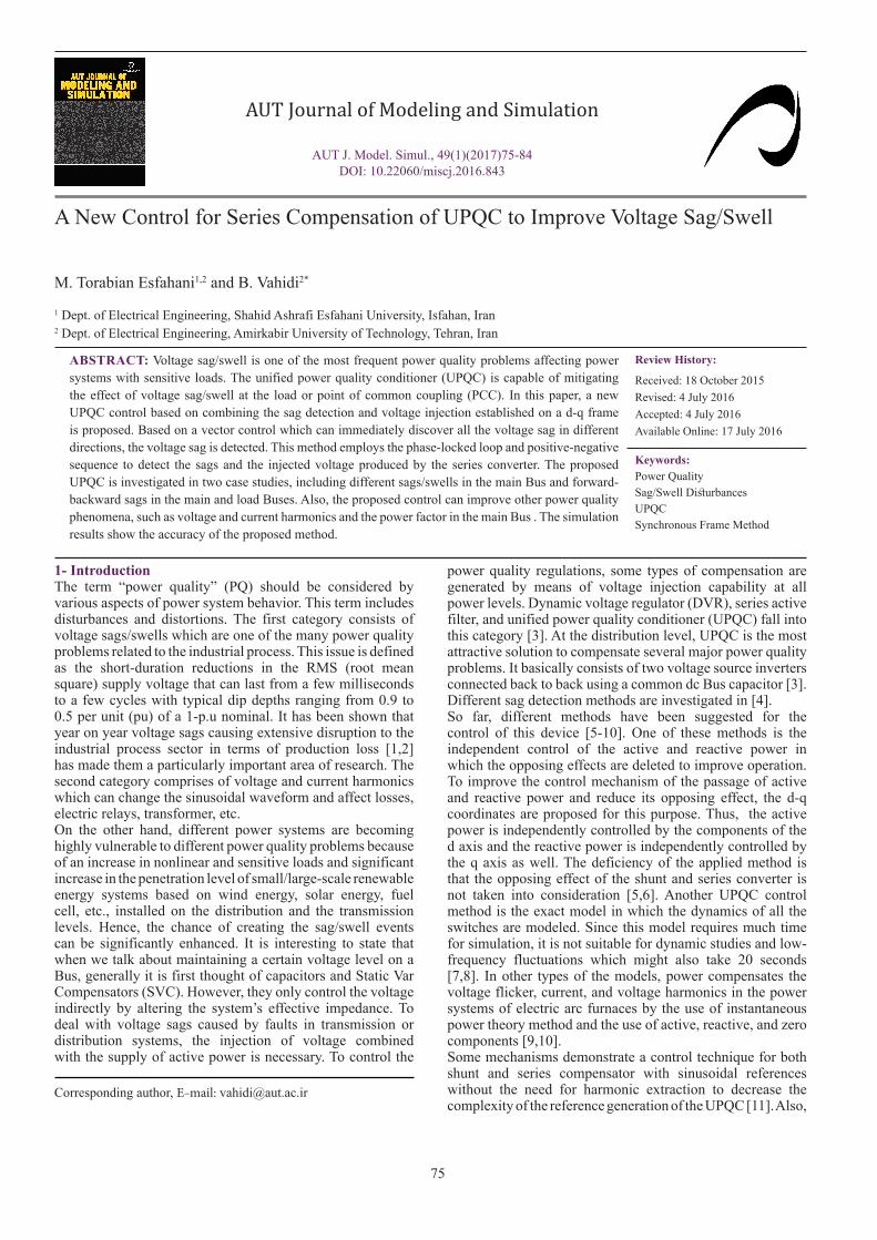
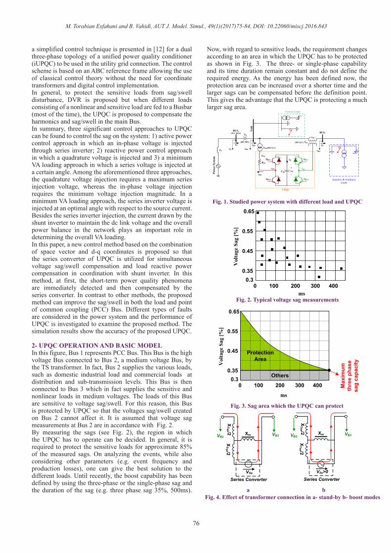
2- UPQC OPERATION AND BASIC MODELIn this figure, Bus 1 represents PCC Bus. This Bus is the high voltage Bus connected to Bus 2, a medium voltage Bus, by the TS transformer. In fact, Bus 2 supplies the various loads, such as domestic industrial load and commercial loads at distribution and sub-transmission levels. This Bus is then connected to Bus 3 which in fact supplies the sensitive and nonlinear loads in medium voltages. The loads of this Bus are sensitive to voltage sag/swell. For this reason, this Bus is protected by UPQC so that the voltages sag/swell created on Bus 2 cannot affect it. It is assumed that voltage sag measurements at Bus 2 are in accordance with Fig. 2.By measuring the sags (see Fig. 2), the region in which the UPQC has to operate can be decided. In general, it is required to protect the sensitive loads for approximate 85% of the measured sags. On analyzing the events, while also considering other parameters (e.g. event frequency and production losses), one can give the best solution to the different loads. Until recently, the boost capability has been defined by using the three-phase or the single-phase sag and the duration of the sag (e.g. three phase sag 35%, 500ms).
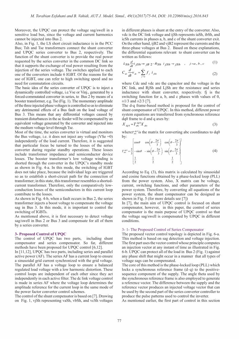
Now, with regard to sensitive loads, the requirement changes according to an area in which the UPQC has to be protected as shown in Fig. 3. The three- or single-phase capability and its time duration remain constant and do not define the required energy. As the energy has been defined now, the protection area can be increased over a shorter time and the larger sags can be compensated before the definition point. This gives the advantage that the UPQC is protecting a much larger sag area.
LS
TS
BUS1(PCC BUS) BUS3
(HV/MV)
Pow
er S
yste
m
Cdc
TSh(MV/LV)ijS
LSh
RSh
+
-vdc
ijL
ijSh
idc
vjS
IgSe1
IgSe2
vjSe
IgSh1
IgSh2
vjSh
+ -vinj.
UPQC
TSe(MV/LV)BU
S2
ijB2
vjB2 vjB3
Sensitive & Nonlinear Loads
Various Loads
Fig. 1. Studied power system with different load and UPQC
0 100 200 300 4000.3
0.35
0.45
0.55
0.65
ms
Vol
tage
Sag
[%]
Fig. 2. Typical voltage sag measurements
0 100 200 300 4000.3
0.35
0.45
0.55
0.65
ms
Vol
tage
Sag
[%]
Protection Area
Others
Max
imum
th
ree
phas
e sa
g ca
paci
ty
Fig. 3. Sag area which the UPQC can protect
VB2 VB3
VSe
Series Converter
XTse /2 Xm
XTse /2
VB2 VB3
VSe>0Series Converter
XTse /2 Xm
XTse /2
a bFig. 4. Effect of transformer connection in a- stand-by b- boost modes
M. Torabian Esfahani and B. Vahidi, AUT J. Model. Simul., 49(1)(2017)75-84, DOI: 10.22060/miscj.2016.843
77
Moreover, the UPQC can protect the voltage sag/swell in a sensitive load bus, since the voltage and current harmonics cannot be injected into Bus 2. Also, in Fig. 1, the LS short circuit inductance is in the PCC Bus; Tsh and Tse transformers connect the shunt converter and UPQC series converter to Bus 2, respectively. The function of the shunt converter is to provide the real power requested by the series converter in the common DC link so that it supports the exchange of real power resulting from the injection of the series voltage. The switches applied to each one of the converters include 6 IGBT. Of the reasons for the use of IGBT, one can refer to high switching speed and no need for commutation circuits. The basic idea of the series converter of UPQC is to inject a dynamically controlled voltage, i.e.Vse or Vinj., generated by a forced-commutated converter in series, to Bus 2 by means of a booster transformer, e.g. Tse (Fig. 1). The momentary amplitude of the three injected phase voltages is controlled so as to eliminate any detrimental effects of a Bus fault on the load voltage of Bus 3. This means that any differential voltages caused by transient disturbances in the ac feeder will be compensated by an equivalent voltage generated by the converter and injected into the medium voltage level through Tse. Most of the time, the series converter is virtual and monitors the Bus voltage, i.e. it does not inject any voltage (VSe =0) independently of the load current. Therefore, it is suggested that particular focus be turned to the losses of the series converter during regular standby operations. These losses include transformer impedance and semiconductor device losses. The booster transformer’s low voltage winding is shorted through the converter in the UPQC’s standby mode as shown in Fig. 4-a. In this mode, the switching of IGBT does not take place, because the individual legs are triggered so as to establish a short-circuit path for the connection of transformer; in this state, this transformer resembles a shorted-current transformer. Therefore, only the comparatively low-conduction losses of the semiconductors in this current loop contribute to the losses.As shown in Fig. 4-b, when a fault occurs in Bus 2, the series transformer injects a boost voltage to compensate the voltage sag in Bus 3. In this mode, it is important to control the switching of IGBTs. As mentioned above, it is first necessary to detect voltage sag/swell in Bus 2 or Bus 3 and compensate for all of them by a series converter.
3- Proposed Control of UPQCThe control of UPQC has two parts, including shunt compensator and series compensator. So far, different methods have been proposed for UPQC control [6,12].In [11,12], UPQC has two parts, including series and parallel active power (AF). The series AF has a current loop to ensure a sinusoidal grid current synchronized with the grid voltage. The parallel AF has a voltage loop to ensure a balanced regulated load voltage with a low harmonic distortion. These control loops are independent of each other since they act independently in each active filter. The dc link voltage control is made in series AF where the voltage loop determines the amplitude reference for the current loop in the same mode of the power factor converter control schemes.The control of the shunt compensator is based on [7]. Drawing on Fig. 1, vjSh representing vaSh, vbSh, and vcSh voltages
in different phases is shunt at the entry of the converter. Also, vdc is the DC link voltage and ijSh represents iaSh, ibSh, and icSh currents in phases a, b, and c of the shunt converter exit. On the other hand, ijB2 and vjB2 represent the currents and the three-phase voltages at Bus 2. Based on these explanations, the differential equations relevant to shunt converter can be written as follows:
where Cdc and vdc are the capacitor and the voltage in the DC link, and RjSh and LjSh are the resistance and series inductance with shunt converter, respectively. fj is the switching function for a, b, and c phases with values of 0, ±1/3 and ±2/3 [7]. The d-q frame-based method is proposed for the control of shunt compensator of UPQC. In this method, different power system equations are transferred from synchronous reference dq0 frame to d and q axes by:
where is the matrix for converting abc coordinates to dq0 by:
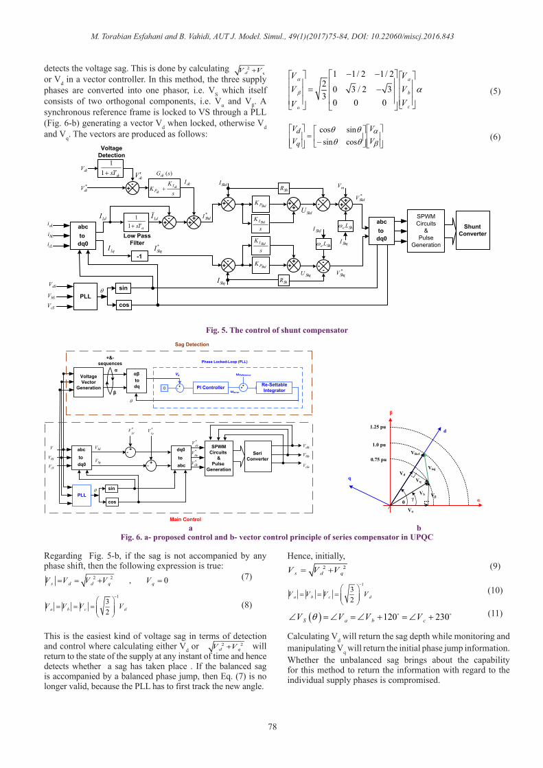
According to Eq. (3), this matrix is calculated by sinusoidal and cosine functions obtained by a phase-locked loop (PLL) from the power system. Also, X matrix can be voltage, current, switching functions, and other parameters of the power system. Therefore, by converting all equations of the power system, the shunt compensator can be designed as shown in Fig. 5 (for more details see [7])In [7], the main aim of UPQC control is focused on shunt compensator, however, in this paper, the control of series compensator is the main purpose of UPQC control so that the voltage sag/swell is compensated by UPQC in different conditions.
3- 1- The Proposed Control of Series CompensatorThe proposed vector control topology is depicted in Fig. 6-a. This method is based on sag detection and voltage injection. The first part uses the vector control whose principle computes an injection vector at any instant of time as illustrated in Fig. 6-b. UPQC can protect all of the load in Bus 2 (Fig. 1) against any phase shift that might occur in a manner that all types of voltage sags can be compensated.The core of this method is the phase-locked loop (PLL) which locks a synchronous reference frame (d–q) to the positive-sequence component of the supply. The angle theta used by the synchronous reference frame is also employed to generate a reference vector. The difference between the supply and the reference vector produces an injected voltage vector that can be used by the second part of the series converter controller to produce the pulse patterns used to control the inverter. As mentioned earlier, the first part of control in this section
, , , 2dL i v R i v j a b cSh jSh jB Sh jSh jShdt
= − − =
c
dc dc j jShj a
dC v f idt =
=∑
00
dqdq abc abcX T X=
0
2 2cos cos cos3 3
2 2 2sin - sin sin3 3 3
1 1 1 2 2 2
dqabcT
π πθ θ θ
π πθ θ θ
− − = − − +
0dqabcT
(1)
(2)
(3)
(4)
M. Torabian Esfahani and B. Vahidi, AUT J. Model. Simul., 49(1)(2017)75-84, DOI: 10.22060/miscj.2016.843
78
detects the voltage sag. This is done by calculating or Vd in a vector controller. In this method, the three supply phases are converted into one phasor, i.e. VS which itself consists of two orthogonal components, i.e. Vα and Vβ. A synchronous reference frame is locked to VS through a PLL (Fig. 6-b) generating a vector Vd when locked, otherwise Vd and Vq. The vectors are produced as follows:
Regarding Fig. 5-b, if the sag is not accompanied by any phase shift, then the following expression is true:
This is the easiest kind of voltage sag in terms of detection and control where calculating either Vd or will return to the state of the supply at any instant of time and hence detects whether a sag has taken place . If the balanced sag is accompanied by a balanced phase jump, then Eq. (7) is no longer valid, because the PLL has to first track the new angle.
2 2d qV V+ 1 1/ 2 1/ 2
2 0 3 / 2 33
0 0 0
a
b
co
V VV V
VV
α
β α
− − = −
−
=
β
αθθθθ
VV
VV
q
dcossinsincos
(5)
(6)
PLLcos
sinθ
aLi
bLi
cLi
aSV
bSV
cSV
sK
K dcdc
IP ++
-dcsT+1
1
*dcV
dcVdcV ′
dcI)(sGdc
Voltage Detection
asT+11
+-
++LdI LdI
Low Pass Filter
-1LqI
abc
dq0to
ShdPK ++
s
KShdI
+ -
ShdPK ++
s
KShdI
+-
ShdI
ShqI
*ShdI
*ShqI
ShdU
ShqUShR
ShR
-- +++
-- -
ShdI
ShqI
mV
*ShqV
*ShdV
abc
dq0to
SPWMCircuits
&Pulse
Generation
Shunt Converter
She Lω
She Lω
Fig. 5. The control of shunt compensator
abc
dq0to
PLLcos
sinθ
abc
dq0to
SPWMCircuits
&Pulse
Generation
Seri Converter
SdV
SqV
*aSe
V*bSe
V
*cSeV
aSeV
bSeV
cSeV
+-
+-
a S
V
bSV
cSV
*Ld
V *Lq
V
Voltage Vector
Generation dqtoαβ
+-0 PI Controller ++Re-Settable Integratorωerror
ωReferenceVq
θ
Phase Locked-Loop (PLL)
Sag Detection
Main Control
α
β
+&- sequences
α
β
d
q
θγ
Vinj
Vα
Vβ
Vd
Vq
VRef
VS
0.75 pu
1.0 pu
1.25 pu
a bFig. 6. a- proposed control and b- vector control principle of series compensator in UPQC
2 2 , 0s d d q qV V V V V= = + =
132a b c dV V V V
−
= = =
(7)
(8)(10)
(11)
(9)
2 2d qV V+
Hence, initially,
Calculating Vd will return the sag depth while monitoring and manipulating Vq will return the initial phase jump information.Whether the unbalanced sag brings about the capability for this method to return the information with regard to the individual supply phases is compromised.
2 2s d qV V V= +
132a b c dV V V V
−
= = =
( ) 120 230S a b cV V V Vθ∠ = ∠ = ∠ + = ∠ +
M. Torabian Esfahani and B. Vahidi, AUT J. Model. Simul., 49(1)(2017)75-84, DOI: 10.22060/miscj.2016.843
79
The supply as seen in both the fixed “α-β” and the synchronous d-q frames may at any instant of time appear to be similar to the vector plot in Fig. 6-b when an unbalanced voltage sag occurs. The unbalanced supply now includes both the negative and positive sequence data. The space vector VS now contains an oscillation with a base frequency of 100 Hz, and when viewed in a synchronous d-q frame locked onto fixed velocity vector (positive sequence) appears as a pure 100 Hz oscillation in the d and q components [4].The Synchronous frame components, i.e. Vd and Vq oscillate with a frequency of 100 Hz as a result of the unbalanced fault or negative sequence which means it can take up to half a cycle before a minimum Vd value is reached. Unlike the case of a balanced fault, there is no direct relationship between the values of Vd and Vq at any instant and the magnitudes of the individual main Bus phases; many different values of the main Bus voltage can give the same Vd and Vq values. An advantage of this method is the relative ease at which it can be implemented within a practical real-time control system [5].Now, the second part of the series converter control system calculates the voltage reference values injected through the series converter. Since the system voltage is sinusoidal, the sinusoidal voltage control strategy is proposed for the control of UPQC series section. In this part, the UPQC series section is controlled in a way that it compensates all the voltage disturbances so that the voltage of the two ends of the load remains as a balanced three-phase sinusoidal voltage. For this purpose, the simultaneous reference frame theory is employed. The desired value of the line phase voltage in d and q axes replace low- and high-pass filters in this method. The line voltage in this state is totally sinusoidal with approximately fixed amplitude and frequency. The desired voltage expected by the line is as follows:
In the following equation, is equal to:
Where Vm is the desired voltage peak value for the line and is the voltage phase angle calculated by PLL. By reducing the desired value of the phase voltage of the d axis (V*Ld) from network voltage (Vsd), all the disturbances in the d axis are obtained .The desired value for the line phase voltage in the q axis is equal to zero. In other words, Vsq expresses all the disturbances in the q axis. Therefore, the series compensation
reference voltage is obtained from equation (14).
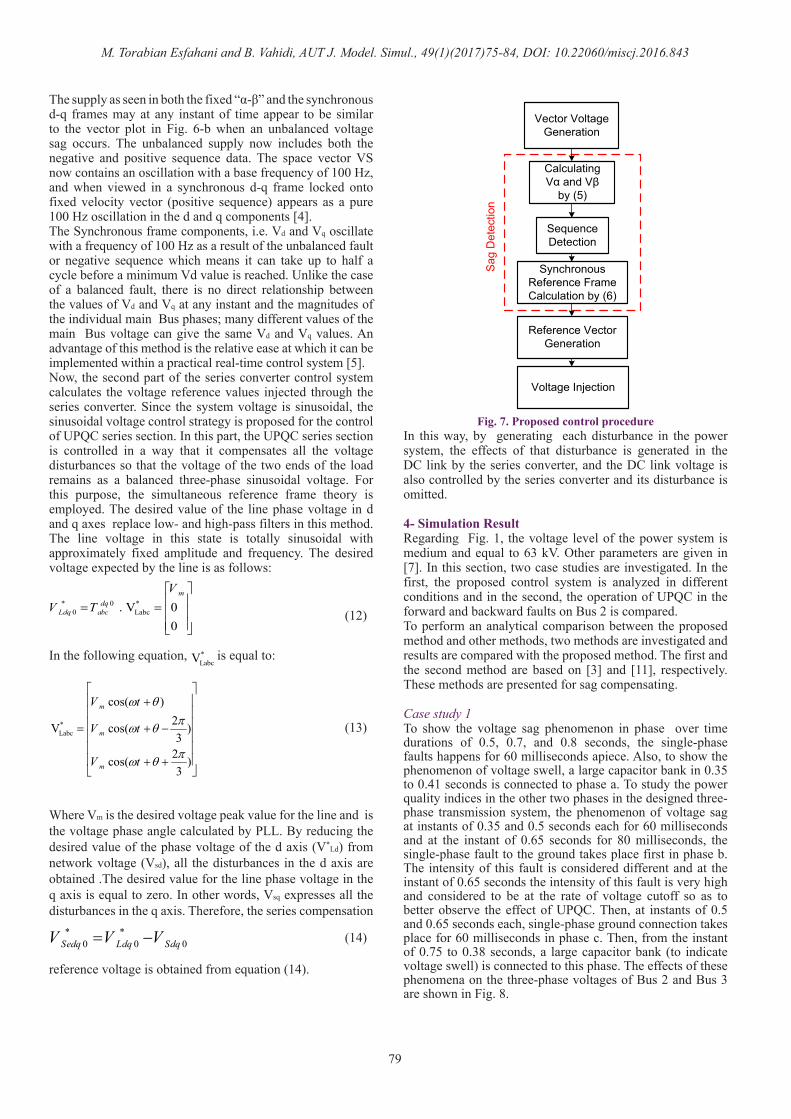
In this way, by generating each disturbance in the power system, the effects of that disturbance is generated in the DC link by the series converter, and the DC link voltage is also controlled by the series converter and its disturbance is omitted.
4- Simulation ResultRegarding Fig. 1, the voltage level of the power system is medium and equal to 63 kV. Other parameters are given in [7]. In this section, two case studies are investigated. In the first, the proposed control system is analyzed in different conditions and in the second, the operation of UPQC in the forward and backward faults on Bus 2 is compared. To perform an analytical comparison between the proposed method and other methods, two methods are investigated and results are compared with the proposed method. The first and the second method are based on [3] and [11], respectively. These methods are presented for sag compensating.
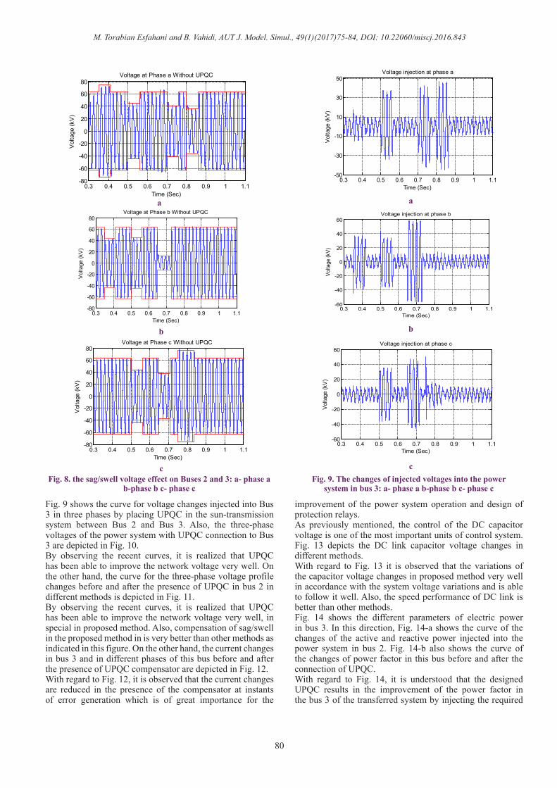
Case study 1To show the voltage sag phenomenon in phase over time durations of 0.5, 0.7, and 0.8 seconds, the single-phase faults happens for 60 milliseconds apiece. Also, to show the phenomenon of voltage swell, a large capacitor bank in 0.35 to 0.41 seconds is connected to phase a. To study the power quality indices in the other two phases in the designed three-phase transmission system, the phenomenon of voltage sag at instants of 0.35 and 0.5 seconds each for 60 milliseconds and at the instant of 0.65 seconds for 80 milliseconds, the single-phase fault to the ground takes place first in phase b. The intensity of this fault is considered different and at the instant of 0.65 seconds the intensity of this fault is very high and considered to be at the rate of voltage cutoff so as to better observe the effect of UPQC. Then, at instants of 0.5 and 0.65 seconds each, single-phase ground connection takes place for 60 milliseconds in phase c. Then, from the instant of 0.75 to 0.38 seconds, a large capacitor bank (to indicate voltage swell) is connected to this phase. The effects of these phenomena on the three-phase voltages of Bus 2 and Bus 3 are shown in Fig. 8.
(12)
(13)
(14)
* 0 *0 Labc . V 0
0
mdq
Ldq abc
VV T
= =
*LabcV
*Labc
cos( )2V cos( )3
2cos( )3
m
m
m
V t
V t
V t
ω θπω θ
πω θ
+ = + − + +
* *0 0 0Sedq Ldq SdqV V V= −
Vector Voltage Generation
Calculating Vα and Vβ
by (5)
Sequence Detection
Synchronous Reference Frame Calculation by (6)
Reference Vector Generation
Voltage Injection
Sag
Det
ectio
n
Fig. 7. Proposed control procedure
M. Torabian Esfahani and B. Vahidi, AUT J. Model. Simul., 49(1)(2017)75-84, DOI: 10.22060/miscj.2016.843
80
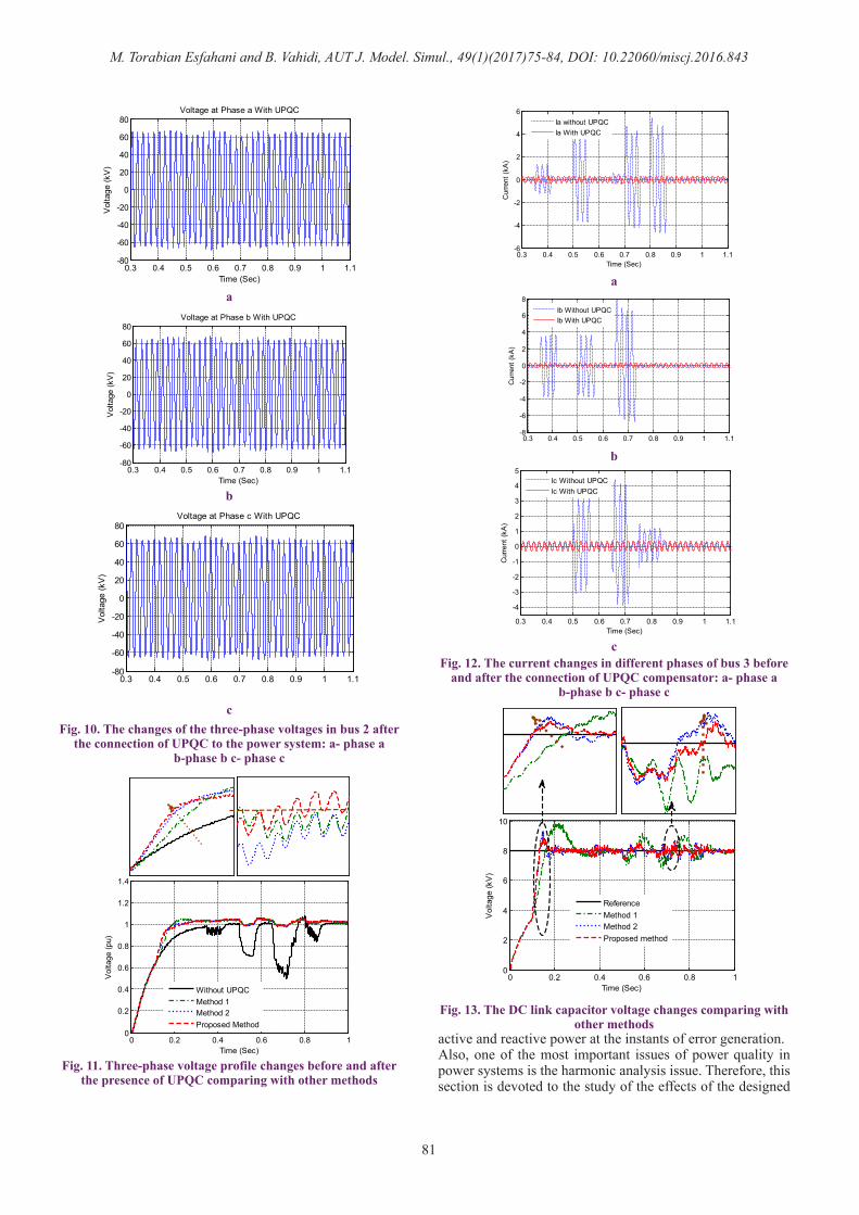
Fig. 9 shows the curve for voltage changes injected into Bus 3 in three phases by placing UPQC in the sun-transmission system between Bus 2 and Bus 3. Also, the three-phase voltages of the power system with UPQC connection to Bus 3 are depicted in Fig. 10.By observing the recent curves, it is realized that UPQC has been able to improve the network voltage very well. On the other hand, the curve for the three-phase voltage profile changes before and after the presence of UPQC in bus 2 in different methods is depicted in Fig. 11.By observing the recent curves, it is realized that UPQC has been able to improve the network voltage very well, in special in proposed method. Also, compensation of sag/swell in the proposed method in is very better than other methods as indicated in this figure. On the other hand, the current changes in bus 3 and in different phases of this bus before and after the presence of UPQC compensator are depicted in Fig. 12.With regard to Fig. 12, it is observed that the current changes are reduced in the presence of the compensator at instants of error generation which is of great importance for the
0.3 0.4 0.5 0.6 0.7 0.8 0.9 1 1.1-80
-60
-40
-20
0
20
40
60
80
Vol
tage
(kV
)
Time (Sec)
Voltage at Phase a Without UPQC
a
b
c
0.3 0.4 0.5 0.6 0.7 0.8 0.9 1 1.1-80
-60
-40
-20
0
20
40
60
80
Time (Sec)
Vol
tage
(kV
)
Voltage at Phase b Without UPQC
0.3 0.4 0.5 0.6 0.7 0.8 0.9 1 1.1-80
-60
-40
-20
0
20
40
60
80Voltage at Phase c Without UPQC
Time (Sec)
Vol
tage
(kV
)
Fig. 8. the sag/swell voltage effect on Buses 2 and 3: a- phase a b-phase b c- phase c
0.3 0.4 0.5 0.6 0.7 0.8 0.9 1 1.1-50
-30
-10
10
30
50
Time (Sec)
Vol
tage
(kV
)
Voltage injection at phase a
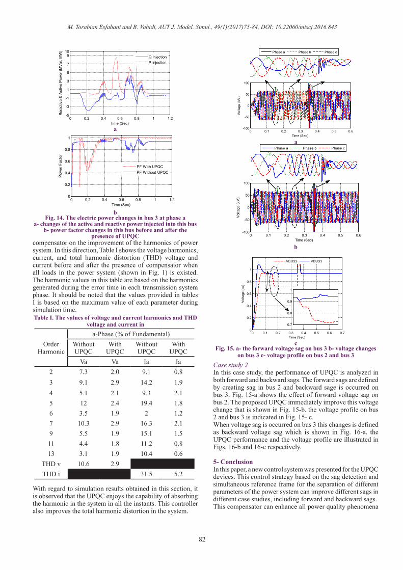
improvement of the power system operation and design of protection relays.As previously mentioned, the control of the DC capacitor voltage is one of the most important units of control system. Fig. 13 depicts the DC link capacitor voltage changes in different methods.With regard to Fig. 13 it is observed that the variations of the capacitor voltage changes in proposed method very well in accordance with the system voltage variations and is able to follow it well. Also, the speed performance of DC link is better than other methods.Fig. 14 shows the different parameters of electric power in bus 3. In this direction, Fig. 14-a shows the curve of the changes of the active and reactive power injected into the power system in bus 2. Fig. 14-b also shows the curve of the changes of power factor in this bus before and after the connection of UPQC.With regard to Fig. 14, it is understood that the designed UPQC results in the improvement of the power factor in the bus 3 of the transferred system by injecting the required
0.3 0.4 0.5 0.6 0.7 0.8 0.9 1 1.1-60
-40
-20
0
20
40
60Voltage injection at phase b
Volta
ge (k
V)
Time (Sec)
b
a
c
0.3 0.4 0.5 0.6 0.7 0.8 0.9 1 1.1-60
-40
-20
0
20
40
60
Time (Sec)
Volta
ge (k
V)
Voltage injection at phase c
Fig. 9. The changes of injected voltages into the power system in bus 3: a- phase a b-phase b c- phase c
M. Torabian Esfahani and B. Vahidi, AUT J. Model. Simul., 49(1)(2017)75-84, DOI: 10.22060/miscj.2016.843
81
active and reactive power at the instants of error generation.Also, one of the most important issues of power quality in power systems is the harmonic analysis issue. Therefore, this section is devoted to the study of the effects of the designed
b
b
aa
c
c
Fig. 10. The changes of the three-phase voltages in bus 2 after the connection of UPQC to the power system: a- phase a
b-phase b c- phase c
Fig. 12. The current changes in different phases of bus 3 before and after the connection of UPQC compensator: a- phase a
b-phase b c- phase c
Fig. 11. Three-phase voltage profile changes before and after the presence of UPQC comparing with other methods
Fig. 13. The DC link capacitor voltage changes comparing with other methods
0.3 0.4 0.5 0.6 0.7 0.8 0.9 1 1.1-80
-60
-40
-20
0
20
40
60
80Voltage at Phase a With UPQC
Time (Sec)
Vol
tage
(kV
)
0.3 0.4 0.5 0.6 0.7 0.8 0.9 1 1.1-80
-60
-40
-20
0
20
40
60
80
Vol
tage
(kV
)
Time (Sec)
Voltage at Phase b With UPQC
0.3 0.4 0.5 0.6 0.7 0.8 0.9 1 1.1-80
-60
-40
-20
0
20
40
60
80Voltage at Phase c With UPQC
Vol
tage
(kV
)
0 0.2 0.4 0.6 0.8 10
0.2
0.4
0.6
0.8
1
1.2
1.4
Time (Sec)
Vol
tage
(pu)
Without UPQCMethod 1Method 2Proposed Method
0.3 0.4 0.5 0.6 0.7 0.8 0.9 1 1.1-6
-4
-2
0
2
4
6
Time (Sec)
Cur
rent
(kA
)
Ia without UPQCIa With UPQC
0.3 0.4 0.5 0.6 0.7 0.8 0.9 1 1.1-8
-6
-4
-2
0
2
4
6
8
Cur
rent
(kA
)
Ib Without UPQCIb With UPQC
0.3 0.4 0.5 0.6 0.7 0.8 0.9 1 1.1
-4
-3
-2
-1
0
1
2
3
4
5
Time (Sec)
Cur
rent
(kA
)
Ic Without UPQCIc With UPQC
0 0.2 0.4 0.6 0.8 10
2
4
6
8
10
Time (Sec)
Vol
tage
(kV
)
ReferenceMethod 1Method 2Proposed method
M. Torabian Esfahani and B. Vahidi, AUT J. Model. Simul., 49(1)(2017)75-84, DOI: 10.22060/miscj.2016.843
82
compensator on the improvement of the harmonics of power system. In this direction, Table I shows the voltage harmonics, current, and total harmonic distortion (THD) voltage and current before and after the presence of compensator when all loads in the power system (shown in Fig. 1) is existed. The harmonic values in this table are based on the harmonics generated during the error time in each transmission system phase. It should be noted that the values provided in tables I is based on the maximum value of each parameter during simulation time.
With regard to simulation results obtained in this section, it is observed that the UPQC enjoys the capability of absorbing the harmonic in the system in all the instants. This controller also improves the total harmonic distortion in the system.
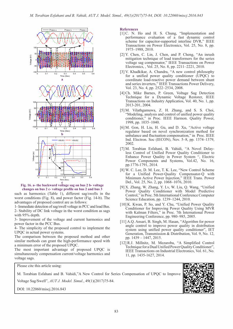
Case study 2In this case study, the performance of UPQC is analyzed in both forward and backward sags. The forward sags are defined by creating sag in bus 2 and backward sage is occurred on bus 3. Fig. 15-a shows the effect of forward voltage sag on bus 2. The proposed UPQC immediately improve this voltage change that is shown in Fig. 15-b. the voltage profile on bus 2 and bus 3 is indicated in Fig. 15- c.When voltage sag is occurred on bus 3 this changes is defined as backward voltage sag which is shown in Fig. 16-a. the UPQC performance and the voltage profile are illustrated in Figs. 16-b and 16-c respectively.
5- Conclusion In this paper, a new control system was presented for the UPQC devices. This control strategy based on the sag detection and simultaneous reference frame for the separation of different parameters of the power system can improve different sags in different case studies, including forward and backward sags. This compensator can enhance all power quality phenomena
Order Harmonic
a-Phase (% of Fundamental)Without UPQC
With UPQC
Without UPQC
With UPQC
Va Va Ia Ia2 7.3 2.0 9.1 0.83 9.1 2.9 14.2 1.94 5.1 2.1 9.3 2.15 12 2.4 19.4 1.86 3.5 1.9 2 1.27 10.3 2.9 16.3 2.19 5.5 1.9 15.1 1.511 4.4 1.8 11.2 0.813 3.1 1.9 10.4 0.6
THD v 10.6 2.9THD i 31.5 5.2
0 0.2 0.4 0.6 0.8 1 1.2-5
-3
-1
1
3
5
7
910
Time (Sec)
Rer
activ
e &
Act
ive
Pow
er (M
Var
, MW
)
Q InjectionP Injection
Fig. 14. The electric power changes in bus 3 at phase aa- changes of the active and reactive power injected into this bus
b- power factor changes in this bus before and after the presence of UPQC
Table I. The values of voltage and current harmonics and THD voltage and current in
Fig. 15. a- the forward voltage sag on bus 3 b- voltage changes on bus 3 c- voltage profile on bus 2 and bus 3
a
a
b
b
c
0 0.2 0.4 0.6 0.8 1 1.20
0.2
0.4
0.6
0.8
1
Time (Sec)
Pow
er F
acto
r
PF With UPQCPF Without UPQC
0 0.1 0.2 0.3 0.4 0.5 0.6-100
-50
0
50
100
Time (Sec)
Vol
tage
(kV
)
Phase a Phase b Phase c
0 0.1 0.2 0.3 0.4 0.5 0.6-100
-50
0
50
100
Time (Sec)V
olta
ge (k
V)
Phase a Phase b Phase c
0 0.1 0.2 0.3 0.4 0.5 0.6 0.70
0.2
0.4
0.6
0.8
1
Time (Sec)
Vol
tage
(pu)
VBUS2 VBUS3
0.7
0.8
0.9
1
VBUS2 VBUS3
M. Torabian Esfahani and B. Vahidi, AUT J. Model. Simul., 49(1)(2017)75-84, DOI: 10.22060/miscj.2016.843
83
such as harmonics (Table 1), different sag/swells in the worst conditions (Fig. 8), and power factor (Fig. 14-b). The advantages of proposed control are as follows:1- Immediate detection of sag/swell voltage in PCC and load Bus.2- Stability of DC link voltage in the worst condition as sags with 95% depth.3- Improvement of the voltage and current harmonics and power factor in the PCC Bus.4- The simplicity of the proposed control to implement the UPQC in actual power systems.The comparison between the proposed method and other similar methods can grant the high-performance speed with a minimum error of the proposed UPQC. The most important advantage of proposed UPQC is simultaneously compensation current/voltage harmonics and voltage sags.
References [1] C. N. Ho and H. S. Chung, “Implementation and
performance evaluation of a fast dynamic control scheme for capacitor-supported interline DVR,” IEEE Transactions on Power Electronics, Vol. 25, No. 8, pp. 1975–1988, 2010.
[2] Y. Chen, C. Lin, J. Chen, and P. Cheng, “An inrush mitigation technique of load transformers for the series voltage sag compensator,” IEEE Transactions on Power Electronics, , Vol. 25, No. 8, pp. 2211–2221, 2010.
[3] V. Khadkikar, A. Chandra, “A new control philosophy for a unified power quality conditioner (UPQC) to coordinate load-reactive power demand between shunt and series inverters,” IEEE Transactions Power Delivery, Vol. 23, No. 4, pp. 2522–2534, 2008.
[4] Ch. Mike Barnes, P. Green, Voltage Sag Detection Technique for a Dynamic Voltage Restorer, IEEE Transactions on Industry Applicatios, Vol. 40, No. 1, pp. 2013-201, 2004.
[5] M. Vilathgamuwa, Z. H. Zhang, and S. S. Choi, “Modeling, analysis and control of unified power quality conditioner,” in Proc. IEEE Harmon. Quality Power, 1998, pp. 1035–1040.
[6] M. Gon, H. Liu, H. Gu, and D. Xu, “Active voltage regulator based on novel synchronization method for unbalance and fluctuation compensation,” in Proc. IEEE Ind. Electron. Soc (IECON), Nov. 5–8, pp. 1374–1379, 2002.
[7] M. Torabian Esfahani, B. Vahidi, “A Novel Delay-less Control of Unified Power Quality Conditioner to Enhance Power Quality in Power System “, Electric Power Components and Systems, Vol.42, No. 16, pp.1776-1791, 2014.
[8] W. C. Lee, D. M. Lee, T. K. Lee, “New Control Scheme for a Unified Power-Quality Compensator-Q with Minimum Active Power Injection,” IEEE Trans. Power Del., Vol. 25, No. 2, pp. 1068–1076, 2010.
[9] X. Zhang, W. Zhang, Y. Lv, W. Liu, Q. Wang, “Unified Power Quality Conditioner with Model Predictive Control,” in Proc. 5th International Conference Computer Science Education, pp. 1239–1244, 2010.
[10] K. Kwan, P. So, and Y. Chu, “Unified Power Quality Conditioner for Improving Power Quality Using MVR with Kalman Filters,” in Proc. 7th International Power Engineering Conference, pp. 980–985, 2005.
[11] A.Q. Ansari, B. Singh, M. Hasan, “Algorithm for power angle control to improve power quality in distribution system using unified power quality conditioner”, IET Generation, Transmission & Distribution, Vol. 9, No. 12, pp. 1439 – 1447, 2015.
[12] R.J. Millnitz, M. Mezaroba, “A Simplified Control Technique for a Dual Unified Power Quality Conditioner”, IEEE Transactions on Industrial Electronics, Vol. 61, No. 11, pp. 1435-1627, 2014.
Fig. 16. a- the backward voltage sag on bus 2 b- voltage changes on bus 2 c- voltage profile on bus 2 and bus 3
a
b
c
0 0.1 0.2 0.3 0.4 0.5 0.6-100
-50
0
50
100
Volta
ge (k
V)
Time (Sec)
Phase a Phase b Phase c
0 0.1 0.2 0.3 0.4 0.5 0.6-100
-50
0
50
100
Time (Sec)
Volta
ge (k
V)
0 0.1 0.2 0.3 0.4 0.5 0.60
0.2
0.4
0.6
0.8
1
Time (Sec)
Volta
ge (p
u)
VBUS3 VBUS2
0.6
0.7
0.8
0.9
1
Please cite this article using:
M. Torabian Esfahani and B. Vahidi,”A New Control for Series Compensation of UPQC to Improve
Voltage Sag/Swell”, AUT J. Model. Simul., 49(1)(2017)75-84.
DOI: 10.22060/miscj.2016.843