Embed Size (px)
Citation preview
A new concept of overhead movable scaffolding system for bridge construction Prof. Dr.-Ing. Pedro Pacheco, BERD, Matosinhos, Portugal; Dipl.-Ing. António Adão da Fonseca, BERD, Matosinhos, Portugal; Dipl.-Ing. Hugo Coelho, BERD, Matosinhos, Portugal; Dipl.-Ing. (FH) Michael Jentsch,Österreichische DOKA GmbH, Amstetten, Österreich Kurzfassung
Untersuchungen und Umsetzung eines neuartigen Systems der Vorspannung werden
vorgestellt, welches durch die Funktionsweise der menschlichen Muskulatur inspiriert wurde.
Dieses System ermöglicht eine stufenlose Kompensation der Verformung von
Tragkonstruktionen aus veränderlichen Belastungszuständen.
Anhand des Beispiels einer oben laufenden Vorschubrüstung mit klappbarer modularer
Aussenschalung erfolgt die Erläuterung dieses Prinzips im Vergleich zu konventionellen
Vorschubgerüsten.
Abstract
In the last decade, a research and development process, initiated in the Faculty of
Engineering of the University of Porto has brought out an innovative technology for bridge
construction: Organic Prestressing. This new technology is now being applied to a brand new
generation of movable scaffolding systems.
The present paper presents a new concept of overhead movable scaffolding systems for in
situ bridge construction, in which the scaffolding structure is similar to a “bowstring”, with the
particularity of having an arched upper chord and an actively controlled lower chord.
1. Introduction
Advantages of organic prestressing application in structures with high “live load / dead load”
ratios and with relatively “slow” loadings, such as movable scaffolding systems used for
bridge construction [1], has promoted an increasing development of this technology in the
past few years.
Inspired on the behaviour of nature structures (biomimetics), more specifically in the muscle
behaviour, Organic Prestressing System (OPS) is an automatically adaptive prestressing
system which has the ability to increase or decrease prestressing forces according to live
load variation. It is no more than a prestressing system in which the tension applied is
automatically adjusted to the actuating loads, through a control system, in order to reduce
the structural deformations and minimize tensions.
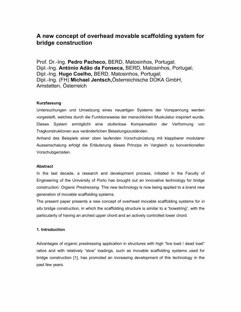
The first OPS movable scaffolding system was designed for the construction of the Rio
Sousa highway bridge in northern Portugal, a double deck comprising 15x30 m long spans
[2]. The scaffolding steel structure comprises four independent main girders (see Fig.1),
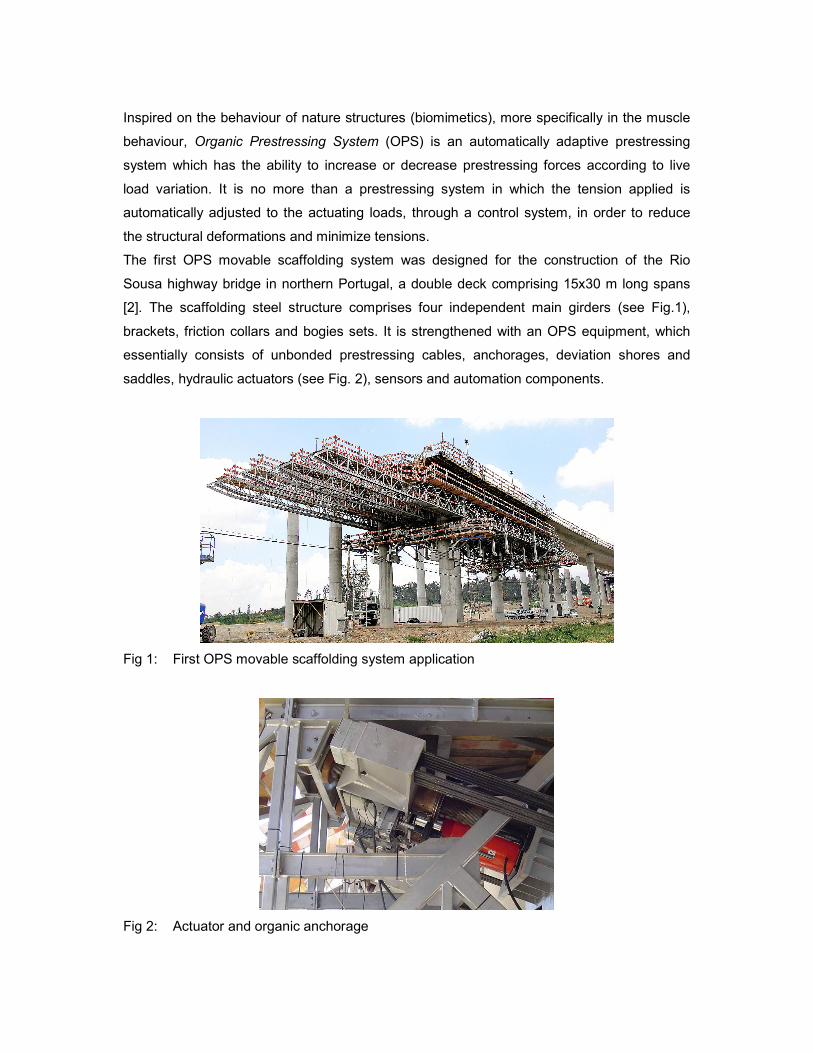
brackets, friction collars and bogies sets. It is strengthened with an OPS equipment, which
essentially consists of unbonded prestressing cables, anchorages, deviation shores and
saddles, hydraulic actuators (see Fig. 2), sensors and automation components.
Fig 1: First OPS movable scaffolding system application
Fig 2: Actuator and organic anchorage
The application of OPS allows for lighter and more functional structures. The maximization of
its potential, whose limits are yet to be established, justifies the design of new types of steel
scaffolding structures, congregating structural advantages and responses to functional
needs, especially of kinematic nature.
A new concept of movable scaffolding system for in situ bridge construction is presented,
namely, an overhead equipment in which the scaffolding structure is similar to a “bowstring”,
with the particularity of having an arched upper chord and an actively controlled lower chord.
This paper includes a presentation of the main concept, a description of the main girder and
of the transverse structures which sustain the formwork and an analysis of their kinematics,
comprising simultaneously structural features and formwork engineering related issues.
Finally, the launching stage is analysed and the main components related with the launching
operations are described.
2. Equipment description
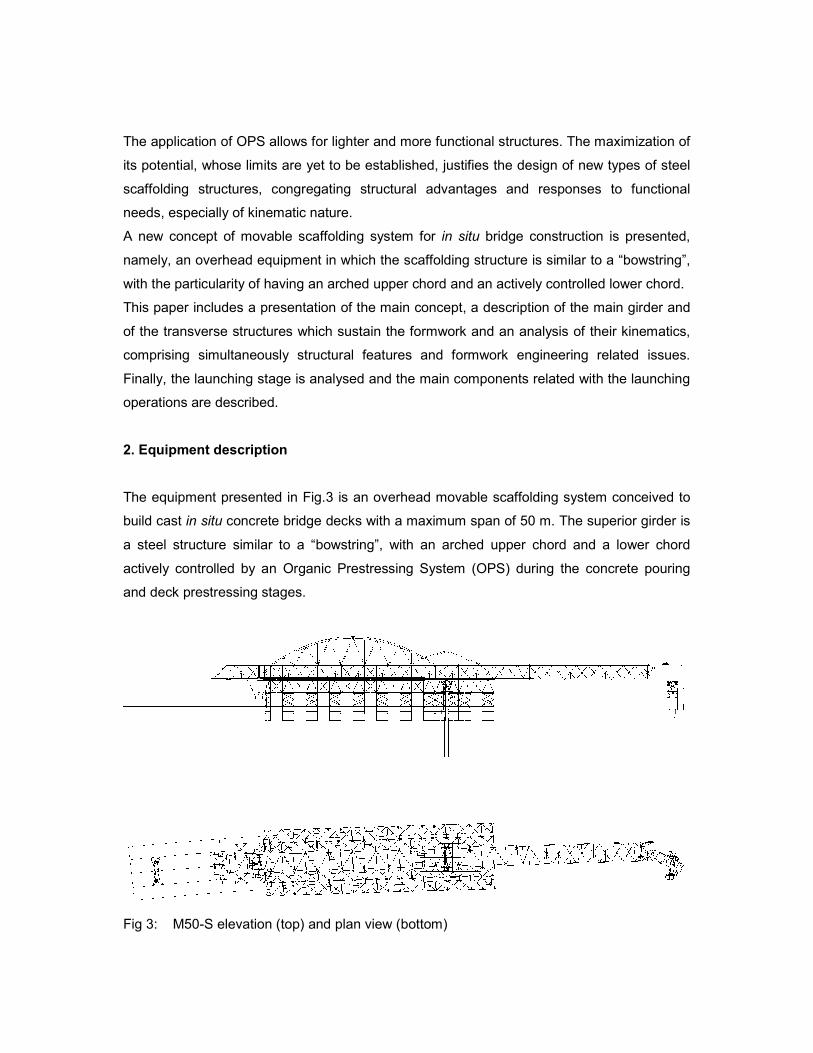
The equipment presented in Fig.3 is an overhead movable scaffolding system conceived to
build cast in situ concrete bridge decks with a maximum span of 50 m. The superior girder is
a steel structure similar to a “bowstring”, with an arched upper chord and a lower chord
actively controlled by an Organic Prestressing System (OPS) during the concrete pouring
and deck prestressing stages.
Fig 3: M50-S elevation (top) and plan view (bottom)
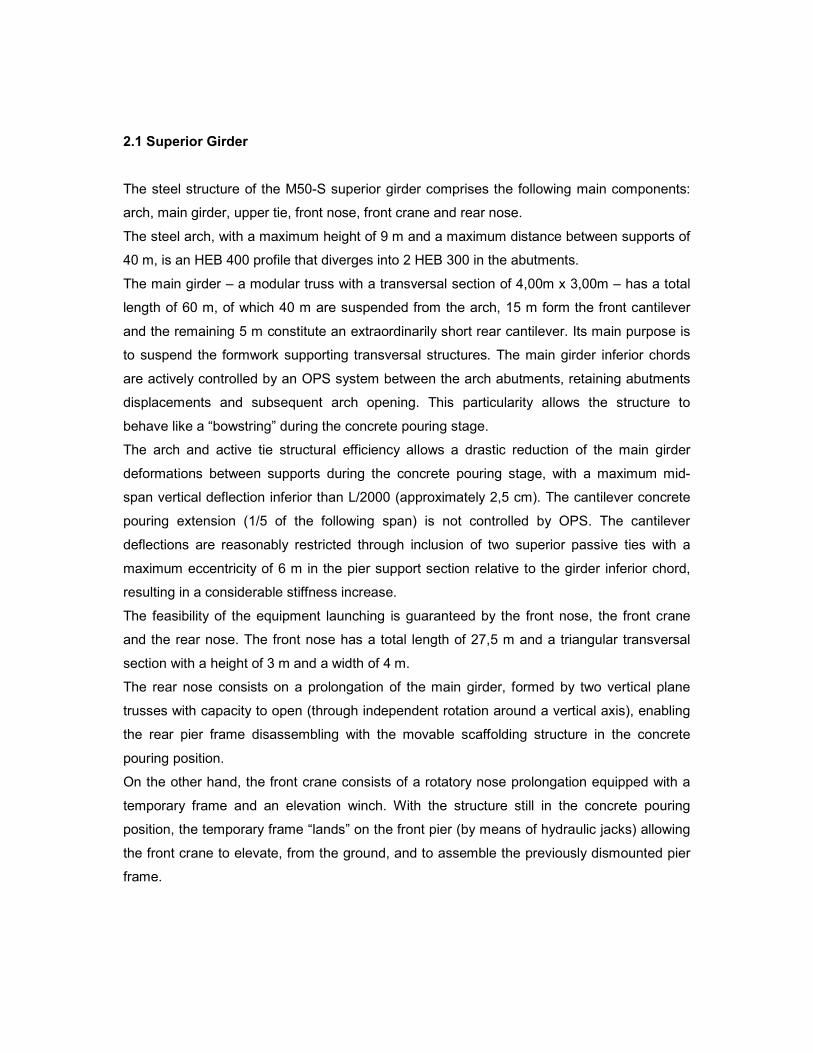
2.1 Superior Girder
The steel structure of the M50-S superior girder comprises the following main components:
arch, main girder, upper tie, front nose, front crane and rear nose.
The steel arch, with a maximum height of 9 m and a maximum distance between supports of
40 m, is an HEB 400 profile that diverges into 2 HEB 300 in the abutments.
The main girder – a modular truss with a transversal section of 4,00m x 3,00m – has a total
length of 60 m, of which 40 m are suspended from the arch, 15 m form the front cantilever
and the remaining 5 m constitute an extraordinarily short rear cantilever. Its main purpose is
to suspend the formwork supporting transversal structures. The main girder inferior chords
are actively controlled by an OPS system between the arch abutments, retaining abutments
displacements and subsequent arch opening. This particularity allows the structure to
behave like a “bowstring” during the concrete pouring stage.
The arch and active tie structural efficiency allows a drastic reduction of the main girder
deformations between supports during the concrete pouring stage, with a maximum mid-
span vertical deflection inferior than L/2000 (approximately 2,5 cm). The cantilever concrete
pouring extension (1/5 of the following span) is not controlled by OPS. The cantilever
deflections are reasonably restricted through inclusion of two superior passive ties with a
maximum eccentricity of 6 m in the pier support section relative to the girder inferior chord,
resulting in a considerable stiffness increase.
The feasibility of the equipment launching is guaranteed by the front nose, the front crane
and the rear nose. The front nose has a total length of 27,5 m and a triangular transversal
section with a height of 3 m and a width of 4 m.
The rear nose consists on a prolongation of the main girder, formed by two vertical plane
trusses with capacity to open (through independent rotation around a vertical axis), enabling
the rear pier frame disassembling with the movable scaffolding structure in the concrete
pouring position.
On the other hand, the front crane consists of a rotatory nose prolongation equipped with a
temporary frame and an elevation winch. With the structure still in the concrete pouring
position, the temporary frame “lands” on the front pier (by means of hydraulic jacks) allowing
the front crane to elevate, from the ground, and to assemble the previously dismounted pier
frame.
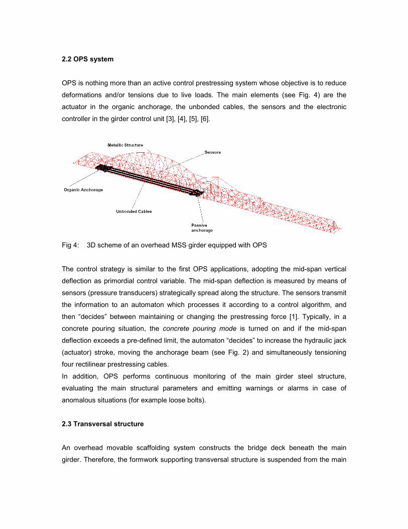
2.2 OPS system
OPS is nothing more than an active control prestressing system whose objective is to reduce
deformations and/or tensions due to live loads. The main elements (see Fig. 4) are the
actuator in the organic anchorage, the unbonded cables, the sensors and the electronic
controller in the girder control unit [3], [4], [5], [6].
Fig 4: 3D scheme of an overhead MSS girder equipped with OPS
The control strategy is similar to the first OPS applications, adopting the mid-span vertical
deflection as primordial control variable. The mid-span deflection is measured by means of
sensors (pressure transducers) strategically spread along the structure. The sensors transmit
the information to an automaton which processes it according to a control algorithm, and
then “decides” between maintaining or changing the prestressing force [1]. Typically, in a
concrete pouring situation, the concrete pouring mode is turned on and if the mid-span
deflection exceeds a pre-defined limit, the automaton “decides” to increase the hydraulic jack
(actuator) stroke, moving the anchorage beam (see Fig. 2) and simultaneously tensioning
four rectilinear prestressing cables.
In addition, OPS performs continuous monitoring of the main girder steel structure,
evaluating the main structural parameters and emitting warnings or alarms in case of
anomalous situations (for example loose bolts).
2.3 Transversal structure
An overhead movable scaffolding system constructs the bridge deck beneath the main
girder. Therefore, the formwork supporting transversal structure is suspended from the main
girder by means of “transversal grips” that guarantee the required width for the formwork.
The transversal structure is materialized by two pairs of steel trusses, each of them
constituted by a horizontal and a vertical truss.
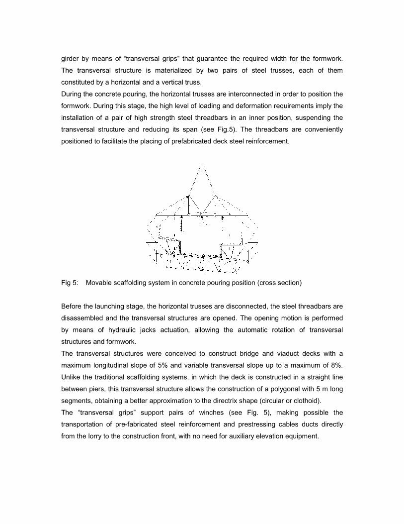
During the concrete pouring, the horizontal trusses are interconnected in order to position the
formwork. During this stage, the high level of loading and deformation requirements imply the
installation of a pair of high strength steel threadbars in an inner position, suspending the
transversal structure and reducing its span (see Fig.5). The threadbars are conveniently
positioned to facilitate the placing of prefabricated deck steel reinforcement.
Fig 5: Movable scaffolding system in concrete pouring position (cross section)
Before the launching stage, the horizontal trusses are disconnected, the steel threadbars are
disassembled and the transversal structures are opened. The opening motion is performed
by means of hydraulic jacks actuation, allowing the automatic rotation of transversal
structures and formwork.
The transversal structures were conceived to construct bridge and viaduct decks with a
maximum longitudinal slope of 5% and variable transversal slope up to a maximum of 8%.
Unlike the traditional scaffolding systems, in which the deck is constructed in a straight line
between piers, this transversal structure allows the construction of a polygonal with 5 m long
segments, obtaining a better approximation to the directrix shape (circular or clothoid).
The “transversal grips” support pairs of winches (see Fig. 5), making possible the
transportation of pre-fabricated steel reinforcement and prestressing cables ducts directly
from the lorry to the construction front, with no need for auxiliary elevation equipment.
2.4 Formwork
The formwork of movable scaffolding systems is, in general, specifically conceived for each
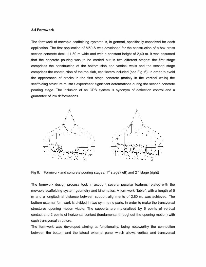
application. The first application of M50-S was developed for the construction of a box cross
section concrete deck, 11,50 m wide and with a constant height of 2,40 m. It was assumed
that the concrete pouring was to be carried out in two different stages: the first stage
comprises the construction of the bottom slab and vertical walls and the second stage
comprises the construction of the top slab, cantilevers included (see Fig. 6). In order to avoid
the appearance of cracks in the first stage concrete (mainly in the vertical walls) the
scaffolding structure mustn´t experiment significant deformations during the second concrete
pouring stage. The inclusion of an OPS system is synonym of deflection control and a
guarantee of low deformations.
Fig 6: Formwork and concrete pouring stages: 1st stage (left) and 2nd stage (right)
The formwork design process took in account several peculiar features related with the
movable scaffolding system geometry and kinematics. A formwork “table”, with a length of 5
m and a longitudinal distance between support alignments of 2,80 m, was achieved. The
bottom external formwork is divided in two symmetric parts, in order to make the transversal
structures opening motion viable. The supports are materialized by 6 points of vertical
contact and 2 points of horizontal contact (fundamental throughout the opening motion) with
each transversal structure.
The formwork was developed aiming at functionality, being noteworthy the connection
between the bottom and the lateral external panel which allows vertical and transversal
adjustments as well as the formwork “table” adaptability to the deck geometry. In addition,
the top slab formwork is launched to the following span concrete pouring position by its own
means.
3 Launching
Throughout the operation of movable scaffolding systems, it is essential to complete the
launching process with safety, speed and efficacy in order to avoid delays and accidents
during the bridge construction, which generally imply substantial economic and human costs.
The present equipment was conceived to perform 1 week cycles, allowing the
accomplishment of demanding deadlines and therefore contributing to a strong reduction of
the bridge construction costs.
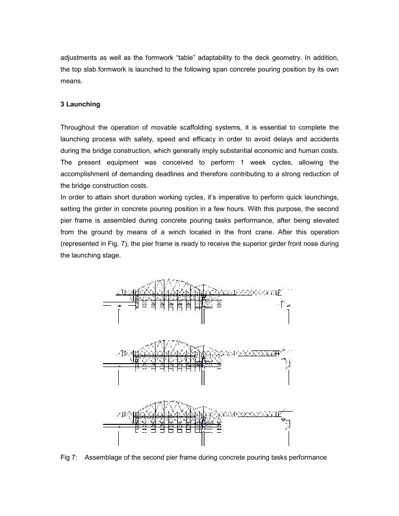
In order to attain short duration working cycles, it’s imperative to perform quick launchings,
setting the girder in concrete pouring position in a few hours. With this purpose, the second
pier frame is assembled during concrete pouring tasks performance, after being elevated
from the ground by means of a winch located in the front crane. After this operation
(represented in Fig. 7), the pier frame is ready to receive the superior girder front nose during
the launching stage.
Fig 7: Assemblage of the second pier frame during concrete pouring tasks performance
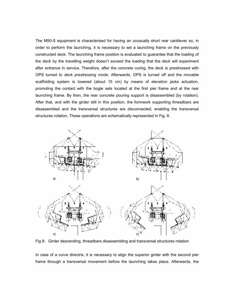
The M50-S equipment is characterised for having an unusually short rear cantilever so, in
order to perform the launching, it is necessary to set a launching frame on the previously
constructed deck. The launching frame position is evaluated to guarantee that the loading of
the deck by the travelling weight doesn’t exceed the loading that the deck will experiment
after entrance in service. Therefore, after the concrete curing, the deck is prestressed with
OPS turned to deck prestressing mode. Afterwards, OPS is turned off and the movable
scaffolding system is lowered (about 15 cm) by means of elevation jacks actuation,
promoting the contact with the bogie sets located at the first pier frame and at the rear
launching frame. By then, the rear concrete pouring support is disassembled (by rotation).
After that, and with the girder still in this position, the formwork supporting threadbars are
disassembled and the transversal structures are disconnected, enabling the transversal
structures rotation. These operations are schematically represented in Fig. 8.
Fig 8: Girder descending, threadbars disassembling and transversal structures rotation
In case of a curve directrix, it is necessary to align the superior girder with the second pier
frame through a transversal movement before the launching takes place. Afterwards, the
launching begins and the movable scaffolding system is moved until the front nose skate
reaches the second pier frame.
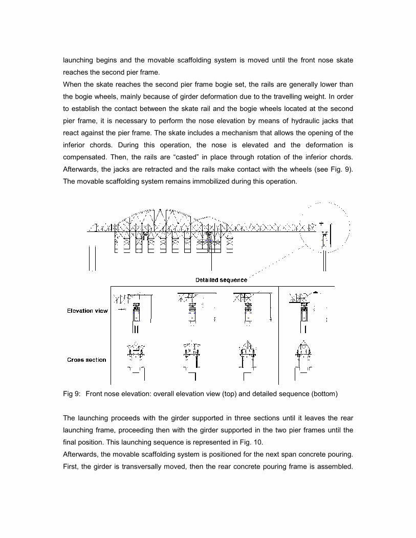
When the skate reaches the second pier frame bogie set, the rails are generally lower than
the bogie wheels, mainly because of girder deformation due to the travelling weight. In order
to establish the contact between the skate rail and the bogie wheels located at the second
pier frame, it is necessary to perform the nose elevation by means of hydraulic jacks that
react against the pier frame. The skate includes a mechanism that allows the opening of the
inferior chords. During this operation, the nose is elevated and the deformation is
compensated. Then, the rails are “casted” in place through rotation of the inferior chords.
Afterwards, the jacks are retracted and the rails make contact with the wheels (see Fig. 9).
The movable scaffolding system remains immobilized during this operation.
Fig 9: Front nose elevation: overall elevation view (top) and detailed sequence (bottom)
The launching proceeds with the girder supported in three sections until it leaves the rear
launching frame, proceeding then with the girder supported in the two pier frames until the
final position. This launching sequence is represented in Fig. 10.
Afterwards, the movable scaffolding system is positioned for the next span concrete pouring.
First, the girder is transversally moved, then the rear concrete pouring frame is assembled.
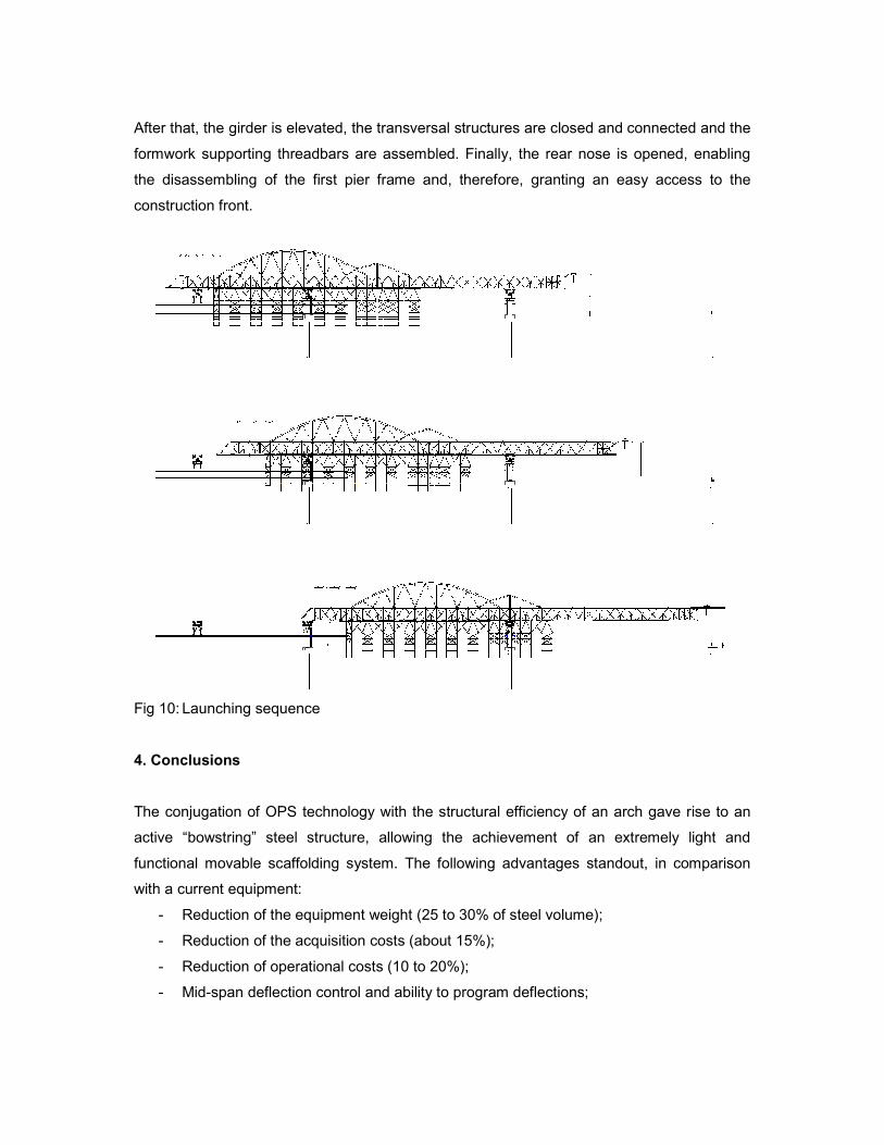
After that, the girder is elevated, the transversal structures are closed and connected and the
formwork supporting threadbars are assembled. Finally, the rear nose is opened, enabling
the disassembling of the first pier frame and, therefore, granting an easy access to the
construction front.
Fig 10: Launching sequence
4. Conclusions
The conjugation of OPS technology with the structural efficiency of an arch gave rise to an
active “bowstring” steel structure, allowing the achievement of an extremely light and
functional movable scaffolding system. The following advantages standout, in comparison
with a current equipment:
- Reduction of the equipment weight (25 to 30% of steel volume);
- Reduction of the acquisition costs (about 15%);
- Reduction of operational costs (10 to 20%);
- Mid-span deflection control and ability to program deflections;
- Continuous monitoring of the scaffolding structure, enabling higher safety levels;
- Easier transportation and on site assemblage of the scaffolding equipment;
- Simplicity of steel connections (maximum tensions substantially reduced).
Moreover, implementation of OPS technology in movable scaffolding systems and,
particularly, in the present equipment, enables the construction of high speed railways bridge
decks, which are substantially heavier (about 30%) than both common railway bridge decks
and highway bridge decks.
Acknowledgments
The authors wish to thank all members of BERD production team for all the work and
dedication throughout the development of the present project: Pedro Borges, António André,
André Resende, Inês Ferraz, Frederico Fonseca, Teresa Oliveira and António Guerra, who
are, indeed, co-authors of this project. Finally, the authors are also grateful to DOKA
Portugal, specially to Sousa Lima and Patrícia Gomes for their commitment in the search of
the best formwork solution.
References
[1] Pacheco P, Adão da Fonseca A. “Organic Prestressing”, Journal of Structural
Engineering, ASCE, 2002, 400-405.
[2] Pacheco P, Guerra A, Borges P, Coelho H. “A Scaffolding System strengthened with
Organic Prestressing – the first of a new generation of structures”, Structural
Engineering International, Journal of IABSE, Vol. 17, N.4, 314-321, 2007.
[3] Pacheco P. “Organic Prestressing – an Effector System example (in Portuguese)”, PhD
Thesis, Dep. Civil. Eng., Faculty of Engineering of the University of Porto, 1999.
[4] André A. “Experimental study of a movable scaffolding system reduced scale model
strengthened with organic prestressing (in Portuguese)”, MSc Thesis, Dep. Civil Eng.,
Faculty of Engineering of the University of Porto, 2005.
[5] Pacheco P. et al, “Strengthening by organic prestressing of existing launching gantries
in the construction of high speed railway bridge decks”, Workshop Bridges for High
Speed Railways, Porto, 289-299, 2004.
[6] André A, Pacheco P, Adão da Fonseca A. “Experimental study of a launching gantry
reduced scale model strengthened with organic presstressing”, Structural Engineering
International, Journal of IABSE, Vol. 16, N.1, 49-52, 2006.