Embed Size (px)
Citation preview
High Pressure ResearchVol. 25, No. 2, June 2005, 107–118
A new belt-type apparatus for neutron-based rheologicalmeasurements at gigapascal pressures
DAVID P. DOBSON*†, JULIAN MECKLENBURGH‡, DARIO ALFE†§,IAN G. WOOD† and MARK R. DAYMOND¶‖
†Department of Earth Sciences, University College London, Gower Street, London WC1E 6BT, UK‡School of Earth, Atmospheric and Environmental Sciences, The University of Manchester,
Oxford Road, Manchester, M13 9PL, UK§Department of Physics and Astronomy, University College London, Gower Street, London,
WC1E 6BT, UK¶ISIS, Rutherford Appleton Laboratories, Chilton, Didcot, Oxfordshire, OX11 0QX, UK
‖Department of Mechanical and Materials Engineering, Queens University, Kingston, Ontario, Canada
(Received 15 March 2005; revised 14 April 2005; in final form 18 April 2005)
We have developed a new solid-media apparatus for performing rheological investigations at multi-gigapascal pressures. The pressure cell consists of a simple belt design and fits in a modified 250 tonneParis–Edinburgh press. Elastic strains are measured by neutron diffraction, on the ENGIN-X experi-mental station at ISIS. Stresses are estimated from the measured strains in combination with publishedvalues of the elastic moduli. As an exemplair of the method, we present data from initial deformationexperiments on pyrope garnet at 1.5 GPa and 873 K. Data collection times are as short as 60 min andthe elastic strain resolution is better than 10−4. We anticipate, however, that by interrupted testing,strain rates as low as 10−9/s, or lower, will be measurable.
Keywords: High pressure; High temperature; Rheology; TOF neutron diffraction
1. Introduction
The knowledge of the rheology of the Earth’s interior is of immense importance. The thermaland physical evolution of the Earth is controlled by convection in the solid silicate mantle,which extends from the brittle crust at ∼100 km depth to the liquid metal outer core at∼2890 km. The strain rate in the mantle is very low, ∼10−14/s, but over the billions of years ofgeological history, the Earth’s surface has been sculpted by the motion of the tectonic plates,which ride on the top of the mantle. The viscosity of the mantle is, however, among the leastwell constrained of all physical properties of the Earth. Traditional gas-media rheologicalequipment can only operate at relatively low pressures, up to 0.3 GPa (equivalent to ∼10 kmdepth). In contrast, solid-media multi-anvil and belt-type devices can achieve pressures in
*Corresponding author. Email: [email protected]
High Pressure ResearchISSN 0895-7959 print/ISSN 1477-2299 online © 2005 Taylor & Francis Group Ltd
http://www.tandf.co.uk/journalsDOI: 10.1080/08957950500143500
108 D. P. Dobson et al.
excess of 25 GPa, i.e. at pressures within the silicate perovskite stability field of the lowermantle.
Recently, there has been a considerable effort in developing rheological devices basedaround multi-anvil technologies. The high internal friction of solid pressure-media rendersdirect measurement of stress ineffectual. Rather, the new solid-media rheology devices usediffraction-based measurements of elastic strain as a proxy for stress. The new rheology devicestherefore need high-penetration and high-flux radiation sources with a wavelength suitable fordiffraction by atomic lattices. Weidner et al. [1] pioneered the use of synchrotron X-ray sourcesin measurements of differential stress as a development from the pseudo-hydrostatic multi-anvil equation of state studies of the 1980s and 1990s. As a further development, the d-DIAcell has the capability of independently moving two opposing anvils, varying the maximumand minimum stresses independently [2]. The precision of strain measurement in this typeof X-ray study is, however, limited by the short wavelengths required for X-ray penetrationof the pressure medium: diffraction patterns are measured at a 2θ angle of ≤6◦; the strainresolution is normally limited to ∼10−4, and measurements of low strain rates below 10−7/srequire very long experimental durations, not usually available at synchrotron sources (see [3]for a recent review).
We have developed a neutron-diffraction-based, solid-media device for measurements atlow strain rates. Neutrons have a significantly higher penetration of most matters than X-rays.Consequently, a large range of wavelengths is available for high-pressure neutron diffractionexperiments. With neutrons, time of flight (TOF) diffraction experiments may be performedat a fixed 2θ , so lattice planes at a single orientation are collected at a given detector, with theprecision in measurement a function of the length of the neutron flight path. The ENGIN-Xbeamline at the CCLRC ISIS facility (Rutherford Appleton Laboratory, Chilton, UK) is opti-mised for strain-partitioning measurements [4]. Two detector banks collect diffracted neutronsat a 2θ of +90◦ and −90◦ with the diffraction vector in the horizontal plane (in practice thedetector banks extend 15◦ above and below the horizontal). The total flight path is 51.5 m andlattice spacings can be measured to give tens of microstrain precision. If a sample is placed atthe focus of the detectors, with the maximum and minimum resolved stresses oriented parallelto θ = ±45◦, each detector bank observes reflections from lattice planes oriented parallelto one of these principal stresses. Thus an axi-symmetric, solid-media device, with neutronaccess at ±45◦ from the axis of compression, will provide the ideal geometry for TOF neu-tron diffraction-based rheological testing equipment, providing measurements of the elasticstrain parallel and perpendicular to the axis of symmetry of the applied differential stress.Here we describe a belt-type device designed for this purpose and present preliminary resultsfrom strain relaxation tests on a natural pyrope garnet at 873 K. Silicate garnet is a substantialcomponent of the lower crust and upper mantle and may play a key role in controlling therheology of these regions [5]. In addition, the cubic symmetry of garnets provides an idealinitial test case for this new apparatus.
2. Cell design
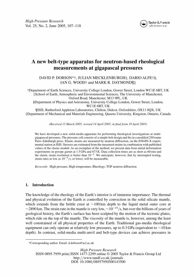
Figure 1 shows a cross-section of the belt-type apparatus and press in the plane of diffraction.The press is a 250 tonne Paris–Edinburgh press [6], which was modified to take the belt-toolingby increasing the tie–rods from 159 to 299 mm in length. The cylindrical belt consists of atungsten carbide core with a 10 mm diameter and 7 mm long sample cavity. The inner surfaceof the carbide core beyond the sample cavity is tapered at 47◦ from the axis of the cylinder, to adiameter of 39 mm. This core is compressed by a strip-wound stress ring, supplied by Strecon,
Apparatus for rheological measurements 109
Figure 1. Cross-section of the belt-type press. Steel components are indicated with diagonal hatching, tungstencarbide is cross-hatched and the ceramic pressure medium and gaskets are represented in grey.
to an interference fit of 1.3%. This provides 1.5 GPa of compression to the outer surface of thecarbide core. Tungsten carbide pistons comprise cones, truncated to 6 mm diameter, cut at 43◦from the axis of the cylinder. The stress ring for the pistons is manufactured from solid high-tensile steel, with slots cut at 45◦ for neutron access, labelled A–D on the figure. The incidentand transmitted beam slots (A and D) are 6 mm diameter parallel-sided cylinders, whereasthe diffracted beam slots extend to ±5◦ in 2θ and ±12◦ in φ. This arrangement providessufficient access for the diffracted beam without significantly affecting the structural integrityof the pistons. The tapers of the pistons and carbide core result in a 4◦ gasket taper, narrowingtowards the sample. This taper enhances the pressure gradient along the gaskets, ensuringthat they provide the maximum support to the sample chamber and high-pressure regions ofthe carbide-tooling while increasing the efficiency of pressure generation and reducing radialstresses on the belt. In addition, the taper reduces the risk of the piston or core impinging onthe neutron path in the case of minor misalignment of the cell. This simple belt profile losessome of the benefits of continuous multi-staging and large attainable compression (�V/V )
of the sample cavity that accompany more complex-curved belt designs, but is optimal forneutron access. We have currently tested the belt to sample pressures in excess of 7 GPa withno breakages.
The sample and gasket assembly are presented in figure 2. The pressure medium and innergasket consist of CaF2, machined from natural massive fluorite from China. These gaskets are4.7 mm thick, measured perpendicular to the cone surface at the point of smallest diameter.
110 D. P. Dobson et al.
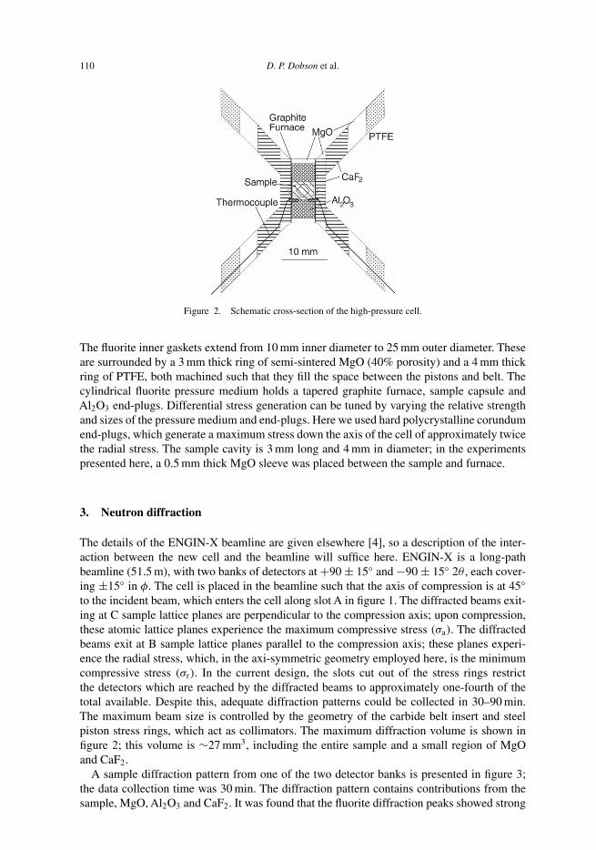
Figure 2. Schematic cross-section of the high-pressure cell.
The fluorite inner gaskets extend from 10 mm inner diameter to 25 mm outer diameter. Theseare surrounded by a 3 mm thick ring of semi-sintered MgO (40% porosity) and a 4 mm thickring of PTFE, both machined such that they fill the space between the pistons and belt. Thecylindrical fluorite pressure medium holds a tapered graphite furnace, sample capsule andAl2O3 end-plugs. Differential stress generation can be tuned by varying the relative strengthand sizes of the pressure medium and end-plugs. Here we used hard polycrystalline corundumend-plugs, which generate a maximum stress down the axis of the cell of approximately twicethe radial stress. The sample cavity is 3 mm long and 4 mm in diameter; in the experimentspresented here, a 0.5 mm thick MgO sleeve was placed between the sample and furnace.
3. Neutron diffraction
The details of the ENGIN-X beamline are given elsewhere [4], so a description of the inter-action between the new cell and the beamline will suffice here. ENGIN-X is a long-pathbeamline (51.5 m), with two banks of detectors at +90 ± 15◦ and −90 ± 15◦ 2θ , each cover-ing ±15◦ in φ. The cell is placed in the beamline such that the axis of compression is at 45◦to the incident beam, which enters the cell along slot A in figure 1. The diffracted beams exit-ing at C sample lattice planes are perpendicular to the compression axis; upon compression,these atomic lattice planes experience the maximum compressive stress (σa). The diffractedbeams exit at B sample lattice planes parallel to the compression axis; these planes experi-ence the radial stress, which, in the axi-symmetric geometry employed here, is the minimumcompressive stress (σr). In the current design, the slots cut out of the stress rings restrictthe detectors which are reached by the diffracted beams to approximately one-fourth of thetotal available. Despite this, adequate diffraction patterns could be collected in 30–90 min.The maximum beam size is controlled by the geometry of the carbide belt insert and steelpiston stress rings, which act as collimators. The maximum diffraction volume is shown infigure 2; this volume is ∼27 mm3, including the entire sample and a small region of MgOand CaF2.
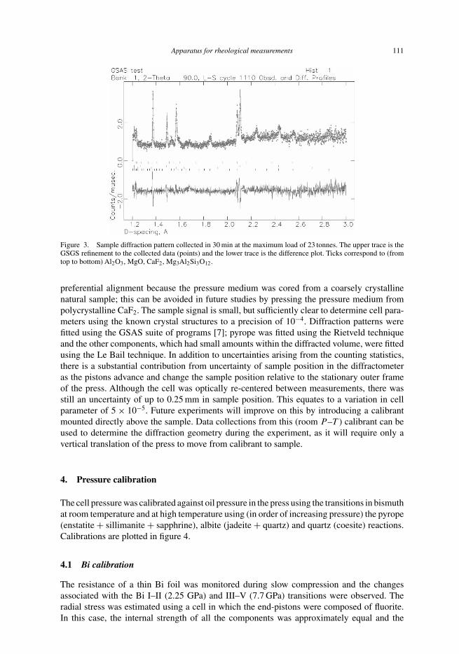
A sample diffraction pattern from one of the two detector banks is presented in figure 3;the data collection time was 30 min. The diffraction pattern contains contributions from thesample, MgO, Al2O3 and CaF2. It was found that the fluorite diffraction peaks showed strong
Apparatus for rheological measurements 111
Figure 3. Sample diffraction pattern collected in 30 min at the maximum load of 23 tonnes. The upper trace is theGSGS refinement to the collected data (points) and the lower trace is the difference plot. Ticks correspond to (fromtop to bottom) Al2O3, MgO, CaF2, Mg3Al2Si3O12.
preferential alignment because the pressure medium was cored from a coarsely crystallinenatural sample; this can be avoided in future studies by pressing the pressure medium frompolycrystalline CaF2. The sample signal is small, but sufficiently clear to determine cell para-meters using the known crystal structures to a precision of 10−4. Diffraction patterns werefitted using the GSAS suite of programs [7]; pyrope was fitted using the Rietveld techniqueand the other components, which had small amounts within the diffracted volume, were fittedusing the Le Bail technique. In addition to uncertainties arising from the counting statistics,there is a substantial contribution from uncertainty of sample position in the diffractometeras the pistons advance and change the sample position relative to the stationary outer frameof the press. Although the cell was optically re-centered between measurements, there wasstill an uncertainty of up to 0.25 mm in sample position. This equates to a variation in cellparameter of 5 × 10⁻⁵. Future experiments will improve on this by introducing a calibrantmounted directly above the sample. Data collections from this (room P –T ) calibrant can beused to determine the diffraction geometry during the experiment, as it will require only avertical translation of the press to move from calibrant to sample.
4. Pressure calibration
The cell pressure was calibrated against oil pressure in the press using the transitions in bismuthat room temperature and at high temperature using (in order of increasing pressure) the pyrope(enstatite + sillimanite + sapphrine), albite (jadeite + quartz) and quartz (coesite) reactions.Calibrations are plotted in figure 4.
4.1 Bi calibration
The resistance of a thin Bi foil was monitored during slow compression and the changesassociated with the Bi I–II (2.25 GPa) and III–V (7.7 GPa) transitions were observed. Theradial stress was estimated using a cell in which the end-pistons were composed of fluorite.In this case, the internal strength of all the components was approximately equal and the
112 D. P. Dobson et al.
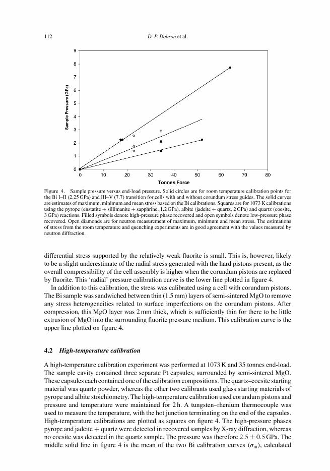
Figure 4. Sample pressure versus end-load pressure. Solid circles are for room temperature calibration points forthe Bi I–II (2.25 GPa) and III–V (7.7) transition for cells with and without corundum stress guides. The solid curvesare estimates of maximum, minimum and mean stress based on the Bi calibrations. Squares are for 1073 K calibrationsusing the pyrope (enstatite + sillimanite + sapphrine, 1.2 GPa), albite (jadeite + quartz, 2 GPa) and quartz (coesite,3 GPa) reactions. Filled symbols denote high-pressure phase recovered and open symbols denote low-pressure phaserecovered. Open diamonds are for neutron measurement of maximum, minimum and mean stress. The estimationsof stress from the room temperature and quenching experiments are in good agreement with the values measured byneutron diffraction.
differential stress supported by the relatively weak fluorite is small. This is, however, likelyto be a slight underestimate of the radial stress generated with the hard pistons present, as theoverall compressibility of the cell assembly is higher when the corundum pistons are replacedby fluorite. This ‘radial’ pressure calibration curve is the lower line plotted in figure 4.
In addition to this calibration, the stress was calibrated using a cell with corundum pistons.The Bi sample was sandwiched between thin (1.5 mm) layers of semi-sintered MgO to removeany stress heterogeneities related to surface imperfections on the corundum pistons. Aftercompression, this MgO layer was 2 mm thick, which is sufficiently thin for there to be littleextrusion of MgO into the surrounding fluorite pressure medium. This calibration curve is theupper line plotted on figure 4.
4.2 High-temperature calibration
A high-temperature calibration experiment was performed at 1073 K and 35 tonnes end-load.The sample cavity contained three separate Pt capsules, surrounded by semi-sintered MgO.These capsules each contained one of the calibration compositions. The quartz–coesite startingmaterial was quartz powder, whereas the other two calibrants used glass starting materials ofpyrope and albite stoichiometry. The high-temperature calibration used corundum pistons andpressure and temperature were maintained for 2 h. A tungsten–rhenium thermocouple wasused to measure the temperature, with the hot junction terminating on the end of the capsules.High-temperature calibrations are plotted as squares on figure 4. The high-pressure phasespyrope and jadeite + quartz were detected in recovered samples by X-ray diffraction, whereasno coesite was detected in the quartz sample. The pressure was therefore 2.5 ± 0.5 GPa. Themiddle solid line in figure 4 is the mean of the two Bi calibration curves (σm), calculated
Apparatus for rheological measurements 113
assuming that the calibration using corundum represents the axial stress and the calibrationusing fluorite pistons represents the radial stress:
σm = σa + 2σr
3(1)
The mean stress, calculated in this manner, is consistent with the high-temperature calibra-tions. In addition, the stresses, σa, σr and σm measured by neutron diffraction (see below) at23 tonnes load and 873 K are plotted as open diamonds in figure 4. All pressure calibrationsare consistent.
5. Rheological testing
5.1 Measurement of strain
The high-strain resolution of the neutron diffraction technique makes it ideal for determiningrheological properties at low strain rates (ε̇) and differential stresses (σd = σa − σr). The belt-type design developed here does not have independent strain control and pressure control,so the stress relaxation technique must be employed [8, 9]. The sample is loaded to somedifferential stress and allowed to deform. There is an instantaneous elastic deformation of thesample:
eεi = sij σj , (2)
where sij are the elastic compliances of the sample and eεi are the elastic strain resulting fromthe applied stress, σj . At high temperature, however, the sample starts to deform plastically:
tε = eε + pε. (3)
If the load cell is sufficiently stiff, that is, if its deformation is negligible, the total strain ( tε)
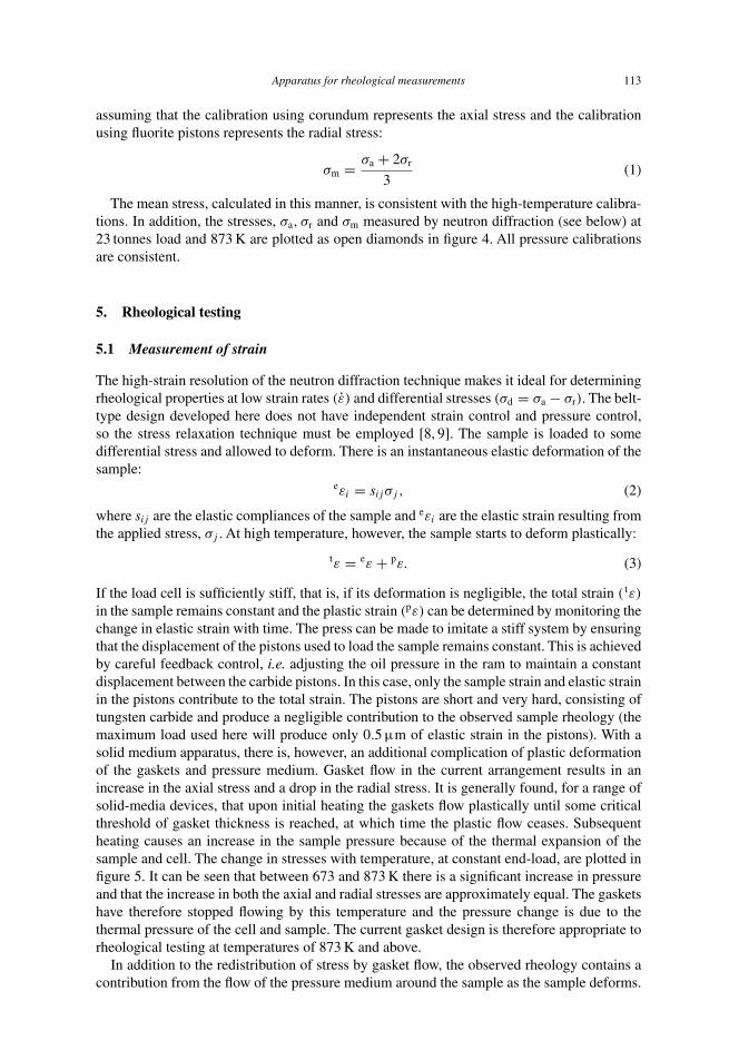
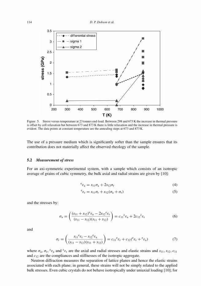
in the sample remains constant and the plastic strain (pε) can be determined by monitoring thechange in elastic strain with time. The press can be made to imitate a stiff system by ensuringthat the displacement of the pistons used to load the sample remains constant. This is achievedby careful feedback control, i.e. adjusting the oil pressure in the ram to maintain a constantdisplacement between the carbide pistons. In this case, only the sample strain and elastic strainin the pistons contribute to the total strain. The pistons are short and very hard, consisting oftungsten carbide and produce a negligible contribution to the observed sample rheology (themaximum load used here will produce only 0.5 µm of elastic strain in the pistons). With asolid medium apparatus, there is, however, an additional complication of plastic deformationof the gaskets and pressure medium. Gasket flow in the current arrangement results in anincrease in the axial stress and a drop in the radial stress. It is generally found, for a range ofsolid-media devices, that upon initial heating the gaskets flow plastically until some criticalthreshold of gasket thickness is reached, at which time the plastic flow ceases. Subsequentheating causes an increase in the sample pressure because of the thermal expansion of thesample and cell. The change in stresses with temperature, at constant end-load, are plotted infigure 5. It can be seen that between 673 and 873 K there is a significant increase in pressureand that the increase in both the axial and radial stresses are approximately equal. The gasketshave therefore stopped flowing by this temperature and the pressure change is due to thethermal pressure of the cell and sample. The current gasket design is therefore appropriate torheological testing at temperatures of 873 K and above.
In addition to the redistribution of stress by gasket flow, the observed rheology contains acontribution from the flow of the pressure medium around the sample as the sample deforms.
114 D. P. Dobson et al.
Figure 5. Stress versus temperature at 23 tonnes end-load. Between 298 and 673 K the increase in thermal pressureis offset by cell relaxation but between 673 and 873 K there is little relaxation and the increase in thermal pressure isevident. The data points at constant temperature are the annealing steps at 673 and 873 K.
The use of a pressure medium which is significantly softer than the sample ensures that itscontribution does not materially affect the observed rheology of the sample.
5.2 Measurement of stress
For an axi-symmetric experimental system, with a sample which consists of an isotropicaverage of grains of cubic symmetry, the bulk axial and radial strains are given by [10]:
eεa = s11σa + 2s12σr (4)eεr = s11σr + s12(σa + σr) (5)
and the stresses by:
σa =(
(s11 + s12)eεa − 2s12
eεr
(s11 − s12)(s11 + s12)
)= c11
eεa + 2c12eεr (6)
and
σr =(
s11eεr − s12
eεa
(s11 − s12)(s11 + s12)
)= c11
eεr + c12(eεr + eεa) (7)
where σa, σr, eεa and eεr are the axial and radial stresses and elastic strains and s11, s12, c11
and c12 are the compliances and stiffnesses of the isotropic aggregate.Neutron diffraction measures the separation of lattice planes and hence the elastic strains
associated with each plane; in general, these strains will not be simply related to the appliedbulk stresses. Even cubic crystals do not behave isotropically under uniaxial loading [10]; for
Apparatus for rheological measurements 115
such crystals, a single-crystal plane-specific modulus, Eh k l , may be written as [11]:
1
Eh k l
= s11 − 2
(s11 − s12 − 1
2s44
) [h2k2 + h2l2 + k2l2(
h2 + k2 + l2)2
](8)
where the term in brackets has limiting values of 0 for h 0 0 reflections and 1/3 for h h h reflec-tions. This equation, however, assumes a ‘free’ single crystal, whereas, in reality, each grainin an aggregate will exhibit elastic properties somewhere between the Reuss bound (uniformstress) and the Voigt bound (uniform strain) [12, 13]. Refs. [11] and [14] give examples of theways in which these problems may be addressed, for example, by including an h k l-dependentpeak shift into a Rietveld refinement program. In the present pilot experiment, the relativelypoor quality of the data prohibits the use of such an approach. We have, instead, simply derivedmean values of eεa and eεr from the ‘Rietveld strains’, i.e. from the lattice parameter valuesdetermined by standard Rietveld refinement (assuming cubic symmetry) of the data from eachof the two detector banks, which sample, respectively, lattice planes aligned perpendicular toand parallel to the axis of the cell.
In order to infer the stresses corresponding to the strains, eεa and eεr, values of the elasticconstants are required. Garnets provide a favourable case for studies such as that reportedhere as they are often very close to being elastically isotropic (i.e. s44 = 2(s11 − s12)) andthus the required moduli for the polycrystalline aggregate calculated in the Voigt and Reussapproximations are almost identical to each other and to those for the free single crystal [15];the differences between measurements for pyrope reported by different workers are far larger.A more serious problem arises from the lack of published data on the pressure and temperaturedependence of individual elastic moduli, dcij /dP and dcij /dT ; in general, only quantities suchas the pressure-dependence of bulk moduli (K ′ = dK/dP) are readily available. A possiblesolution to this problem in future work would be to combine the values of cij measured underambient conditions with first-principles computer simulation of their pressure and temperaturedependence [16]. In the present pilot study we have considered it sufficient to use the single-crystal values of c11 = 296.2 GPa and c12 = 111.1 GPa measured under ambient conditions[17], as to some extent the increase in stiffness produced by the elevated pressure will be offsetby softening at high temperature.
6. Sample data: strength of Dora Maira pyrope at 873 K
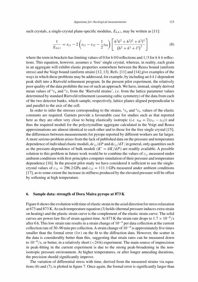
Figure 6 shows the evolution with time of elastic strain in the axial direction for stress relaxationat 673 and 873 K.At each temperature equation (3) holds (thermal pressure induces extra strainon heating) and the plastic strain curve is the complement of the elastic strain curve. The solidcurves are power-law fits of strain against time. At 873 K the strain rate drops to 1.7 × 10⁻⁸/safter 6 h. This low strain rate results in a strain change of 10−4 per data collection at the currentcollection rate of 30–90 min per collection.A strain change of 10−4 is approximately five timessmaller than the formal error (1σ) on the fit to the diffraction data. However, the scatter inthe data is considerably better than this, suggesting that strain rates can be measured downto 10−8/s, or better, in a relatively short (<24 h) experiment. The main source of imprecisionin peak-fitting in the current experiment is due to the strong peak-broadening in the non-isotropic pressure environment. At higher temperatures, or after longer annealing durations,the precision should significantly improve.
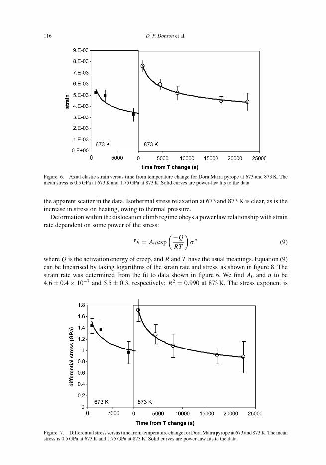
The variation of differential stress with time, derived from the measured strains via equa-tions (6) and (7), is plotted in figure 7. Once again, the formal error is significantly larger than
116 D. P. Dobson et al.
Figure 6. Axial elastic strain versus time from temperature change for Dora Maira pyrope at 673 and 873 K. Themean stress is 0.5 GPa at 673 K and 1.75 GPa at 873 K. Solid curves are power-law fits to the data.
the apparent scatter in the data. Isothermal stress relaxation at 673 and 873 K is clear, as is theincrease in stress on heating, owing to thermal pressure.
Deformation within the dislocation climb regime obeys a power law relationship with strainrate dependent on some power of the stress:
pε̇ = A0 exp
(−Q
RT
)σn (9)
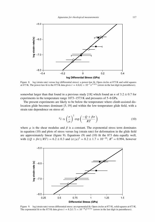
where Q is the activation energy of creep, and R and T have the usual meanings. Equation (9)can be linearised by taking logarithms of the strain rate and stress, as shown in figure 8. Thestrain rate was determined from the fit to data shown in figure 6. We find A0 and n to be4.6 ± 0.4 × 10⁻⁷ and 5.5 ± 0.3, respectively; R2 = 0.990 at 873 K. The stress exponent is
Figure 7. Differential stress versus time from temperature change for Dora Maira pyrope at 673 and 873 K. The meanstress is 0.5 GPa at 673 K and 1.75 GPa at 873 K. Solid curves are power-law fits to the data.
Apparatus for rheological measurements 117
Figure 8. log (strain rate) versus log (differential stress): a power-law fit. Open circles at 873 K and solid squaresat 673 K. The power-law fit to the 873 K data gives ε̇ = 4.6(4) × 10−7σ 5.5(3) (errors in the last digit in parentheses).
somewhat larger than that found in a previous study [18] which found an n of 3.2 ± 0.7 forexperiments in the temperature range 1073–1573 K and pressures of 5–6 GPa.
The present experiments are likely to be below the temperature where climb-assisted dis-location glide becomes dominant [5, 19] and within the low-temperature glide field, with astrain rate dependence on stress of:
pε̇ ∝(
σ
µ
)2
exp
(−Q + βσ
RT
)(10)
where µ is the shear modulus and β is a constant. The exponential stress term dominatesin equation (10) and plots of stress versus log (strain rate) for deformation in the glide fieldare approximately linear (figure 9). Equations (9) and (10) fit the 873 data equally well,with ((Q + βσ)/RT ) = 6.2 ± 0.3 and (σ/µ)2 = 8.2 ± 1.7 × 10⁻¹⁰; R2 = 0.994, however
Figure 9. log (strain rate) versus differential stress: an exponential fit. Open circles at 873 K, solid squares at 673 K.The exponential fit to the 873 K data gives ε̇ = 8.2(1.7) × 10−10e6.2(3)σ (errors in the last digit in parentheses).
118 D. P. Dobson et al.
the similarity of the stress dependence at 673 and 873 K suggests that the current experimentsare in the glide field with a weak temperature dependence. The observed strain rate at 873 Kand 0.5 GPa differential stress is two orders of magnitude higher than the value extrapolatedfrom Li et al. [18] to the same conditions, consistent with a change in mechanism between1073 and 873 K.
7. Summary and conclusion
The new belt-type device presented here provides a high-pressure environment for strainmeasurements using the ENGIN-X neutron diffractometer at pressures up to at least 7 GPa.Data collections of 60 min, or shorter, allow time series to be collected for stress relaxationexperiments. The counting rate can be further improved by minor modifications (currentlyunder construction) to the cell and piston design and we expect in the future to be able to usethe entire detector bank on ENGIN-X, increasing the data rate by a factor of four. The high-strain resolution possible on ENGIN-X allows strain rates of 10−9/s, or lower, to be readilydetermined by the use of interrupted testing. Attaining very low strain rates is important forextrapolations to geological conditions; the device presented here currently provides the lowestattainable strain rates of the high-pressure rheological devices.
References[1] D.J. Weidner, Y. Wang, G. Chen et al., in Properties of Earth and Planetary Materials at High Pressure and
Temperature, Geophysics Monographs volume 101, p. 473, edited by M. Manghnani and Y. Yagi (AmericanGeophysical Society, Washington DC, 1998).
[2] Y.B. Wang, W.B. Durham and I.C. Getting, Rev. Sci. Instrum. 74 3002 (2003).[3] W.B. Durham, D.J. Weidner, S.I. Karato et al., Rev. Mineral. Geochem. 51 21 (2002).[4] M.W. Johnson and M.R. Daymond, J. Appl. Cryst. 35 49 (2002).[5] Z.C. Wang and S.C. Ji, Can. Mineral. 37 525 (1999).[6] J.M. Besson, R.J. Nelmes, G. Hamel et al., Physica B 180 and 181 907 (1992).[7] A.C. Larson and R.B. Von Dreele, Los Alamos Laboratory Report LA-UR-86-748 (1986).[8] E.H. Rutter, B.K. Atkinson and D.H. Mainprice, Geophys. J. Roy. Astro. Soc. 55 155 (1978).[9] S.J. Covey-Crump, J. Geophys. Res. 103 29781 (1998).
[10] J.F. Nye, Physical Properties of Crystals: Their Representation by Tensors and Matrices (Oxford UniversityPress, 1985).
[11] M.R. Daymond, M.A.M. Bourke, R.B. Von Dreele et al., J. Appl. Phys. 82 1554 (1997).[12] J.P. Poirier, Introduction to the Physics of the Earth’s Interior (Cambridge University Press, Cambridge, 1991).[13] J.M.J. den Toonder, J.A.W. van Dommelen and F.P.T. Baaijens, Model Simul. Mater. Sci. 7 909 (1999).[14] M.R. Daymond, J. Appl. Phys. 96 4263 (2004).[15] G. Simmonds and H. Wang, Single Crystal Elastic Constants and Calculated Aggregate Properties: A Handbook,
2nd edn (M.I.T. Press, Cambridge MA, 1971).[16] L. Vocadlo, D. Alfe, M.J. Gillan et al., Phys. Earth Planet. Sci. 140 101 (2003).[17] B. O’Neill, J.D. Bass, G.R. Rossman et al., Phys. Chem. Mineral. 17 617 (1991).[18] L. Li, P. Raterron and D. Weidner, submitted to American Mineralogist.[19] V. Voegele, J.I. Ando, P. Cordier et al., Phys. Earth Planet. Int. 108 305 (1998).