Embed Size (px)
Citation preview

A New Approach to Machine Safety:
EN ISO 13 849-1:2006 – Safety-related Parts of Control Systems
Category
S1
B1234
S2
F1P1
P2
P1
P2 F2
Low
risk
Starting point
to gauge
risk reduction
performance
level PLr
Required
S1
F1FF
F2FF
F1FF
P1
a
b
c
d
P2PP
P1
P
P1
P2PP

2
A New Approach to Machine Safety:
EN ISO 13 849-1:2006 – Safety-related Parts of Control Systems
Dear Customer,
Dear Customer,
After having had some more internal trouble
the revision of the present standard ISO
13 849-1:1999 (EN 954-1:1996) has passed in
autumn of 2006 and the new EN ISO 13 849-
1:2006: “Safety-related Parts of Control
Systems” (as its successor) has become into
force.
To say it in other words: The paradigm shift
in the philosophy of safety-related parts
of machine control systems takes place to
supplement probabilistic considerations to the
previous proven in use deterministic consider-
ations.
Therefore the time table of coming into force
on page 46 of our brochure “A new Approach
of Machine Safety: prEN ISO 13 849-1” (with
an editorial deadline of March 2006) needs an
update.
According the latest decision-making process
the now concluded standard has a transition
period until November 2009 (which means the
new provisions can be already applied from
now on, but there is not yet a must to do so).
But in November 2009 at the latest confl ict-
ing standards (in practical terms: ISO 13 849-
1:1996 respectively EN 954-1:1996) have to be
recalled. Than the “old” standard fi nally will be
replaced by EN ISO 13 849-1:2006.
In all other respects our brochure on back-
grounds, application and practical implemen-
tation of the new standard are still up-to-date
and (besides some smaller printing mistakes)
correct.
Yours sincerely,
Friedrich Adams
K.A. Schmersal Holding GmbH & Co. KG
Wuppertal/Wettenberg in May 2007
When do I have to apply the new EN ISO 13 849-1:2006?Is there any transition period?
Middle of 2006Final draft (FDIS)
Late summer 2006Voting
Herbst 2006Adoption
Transition period November 2009
Harmonizing First quarter of 2007
✔
Update
3
Highrisk
Lowrisk
Starting pointto gauge
risk reduction
performance level PLr
Required
S1
S2
F1
F2
F1
F2
P1a
b
c
d
e
P2
P1
P2
P1
P2
P1
P2
Dear Customer,
Dear Customer,
In this brochure we extensively highlight the
core speech at the Elan lecture event 2005,
which dealt with the discontinuation of the
EN 954-1 standard and the new regulations
in the revised standard EN ISO 13 849-1. With
the initiative to release this brochure, the
SCHMERSAL Group intents to emphasise their
advanced competence on safety of machinery.
For us as a supplier of safety switchgear and
safety systems designed to protect people,
machines and equipment we also wish to pro-
vide our customers with additional information
on boundaries and background knowledge
in order to become their partner of prefer-
ence when it comes to the implementation of
safety components for machines and machine
controls.
Below is a summary of the relevant speech by
Mr. Thomas Bömer (engineer) and Mr. Karl-
Heinz Büllesbach (engineer), both employees
of the Berufsgenossenschaftliches Institut für
Arbeitsschutz BGIA (the employer’s liability
insurance association institute for health and
safety – BGIA) in St. Augustin, whose work at
the “electronics” unit within the machine pro-
tection & control systems engineering depart-
ment there is closely related to our theme. The
fi gures in the following contribution are based
on the PPT presentation of the two gentlemen;
thus the copyright for the fi gures belongs to
them.
The Berufsgenossenschaftliches Institut für
Arbeitsschutz BGIA in particular, as well as
various engineering-oriented employer’s liabil-
ity insurance associations have been espe-
cially committed to the design of the revised
standard EN ISO 13 849-1. In the foreground
are the clientele of small and medium sized en-
gineering and control systems companies who
are to be given a guide on the future execution
of safety-related control system parts which is
as simple but also as substantial as possible.
If the enactment of EN ISO 13 849-1:2006 is
nevertheless currently highly contentious, this
is connected with a particular constellation
within the standards scene, in which the sector
specifi c IEC EN 62 061 standard (derived from
IEC EN 61 508) is also competing to replace
EN 954-1, even if only in the area of electri-
cal, electronic and programmable electronic
systems with safety functions.
Irrespective of this, the product range from the
companies in the SCHMERSAL Group already
takes account of and can now support both
future standards with the relevant specifi ca-
tions. If you have any questions pertinent to
this subject therefore, please discuss them
with us.
In the interests of clarity we have divided
the theme of “EN ISO 13 849-1:2006: A New
Approach to Machine Safety” into separate
sections which are themselves subdivided
– subject to how “deeply” you wish to probe
while reading.
We ask for your understanding with respect
of abbreviations in the text in advance (which
are unfortunately unavoidable). The glossary,
however, tries to maintain readability (please
refer to the fold out page).
Although we have attempted to make the sum-
mary clear and comprehensible, this may only
have succeeded in part due to the complexity
of the subject. Unanswered questions are also
bound to occur at different points.
Nevertheless, we hope you fi nd this reading
interesting and look forward to working with
you in the future.
Yours sincerely,
Heinz Schmersal
Managing Director
K.A. Schmersal Holding GmbH & Co. KG
Friedrich Adams
K.A. Schmersal Holding GmbH & Co. KG
Wuppertal/Wettenberg in March 2006

4
A New Approach to Machine Safety:
EN ISO 13 849-1:2006 – Safety-related Parts of Control Systems

5
Highrisk
Lowrisk
Starting pointto gauge
risk reduction
performance level PLr
Required
S1
S2
F1
F2
F1
F2
P1a
b
c
d
e
P2
P1
P2
P1
P2
P1
P2
A New Approach to Machine Safety:
EN ISO 13 849-1:2006 – Safety-related Parts of Control Systems
Contents
Page
Introduction 6
Background to the removal of EN 954-1 7
New risk chart 9
Designated Architectures 13
MTTFd value 15
Diagnostic Coverage 23
Common cause failure management (CCF) 26
Example 27
Validation 32
SiSteMa 34
EN ISO 13 849-1:2006 and clear SRP/CS 36
EN ISO 13 849-1:2006 when serially aligned 38
EN ISO 13 849-1:2006 and software 40
EN ISO 13 849-1:2006 vs. EN 62 061 43
Enactment of EN ISO 13 849-1:2006 46
FAQs 47
Outlook 49
Glossary: refer to the fold-out page on Page 51
Publisher
Elan Schaltelemente GmbH & Co. KG
Im Ostpark 2
35435 Wettenberg
Telephone +49 (0)641 9848-0
Fax +49 (0)641 9848-420
E-Mail: [email protected]
Internet: www.elan.de
Editor
Friedrich Adams
c/o SCHMERSAL Holding GmbH & Co. KG
Möddinghofe 30
42279 Wuppertal
E-Mail: [email protected]
Overall production
Werbe-Grafi k Heinz Flick, 35075 Gladenbach/
Druckteam Peter Bork, 35435 Wettenberg
!

6
A New Approach to Machine Safety:
EN ISO 13 849-1:2006 – Safety-related Parts of Control Systems
Introduction
When EN 954-1¹ is replaced in a few years
– something we now take for granted – this
will also represent a kind of paradigm shift.
In future, the importance of the deterministic
approach to executing safety-related control
system parts will decline and probability ap-
proaches will emerge.
Two standards are competing to be the suc-
cessor to EN 954-1: the fi rst is EN ISO 13 849-
1:2006², which has been specifi cally designed
to follow on from EN 954-1. The second
standard competing to succeed EN 954-1 is
IEC EN 62 061³, a sector-specifi c derivative of
IEC EN 61 5084.
The theory of probability with regard to the
execution of safety-related parts of machine
controls will also hold in the future with either
standard (at least with regard to the generic
term for reliability engineering), irrespective of
the decision taken. In contrast, the approach in
EN 954-1 is based essentially on an examina-
tion of structures.
Although we will concentrate on EN ISO
13 849-1:2006 in the following article, based
on the contents of the Elan lecture event 2005,
probabilistics in the form of the mathematical
calculus of probability theory and modelling
play a much greater role in IEC EN 61 508 and
IEC EN 62 061. In contrast, the standard-setter
of EN ISO 13 849-1:2006 has strived to achieve
a delicate balancing act between deterministic
and probabilistic thinking, breaking down the
new aspects into a requisite and practicable
size for the “average user” (refer to Figure 1).
1) EN 954-1: 1997-03: Safety of safety-related parts
of control systems – Part 1: general design guide-
lines (corresponds also to ISO 13 849-1: 1999-11)
2) EN ISO 13 849-1:2006: Safety of machine safety-
related parts of control systems – Part 1: General
design guidelines.
3) IEC EN 62 061:2005-10: Safety of machines – func-
tional safety of safety-related electrical, electronic
and programmable electronic control systems
4) IEC EN 61 508:2002-11: Functional safety of
safety-related electrical/electronic/programmable
electronic systems
Part 1: General requirements
Part 2: Requirements of safety-related electrical/
electronic/programmable electronic
systems
Part 3: Requirements of software
Part 4: Terms and abbreviations
Part 5: Examples to calculate the safety integrity
level
Part 6: Application guidelines for IEC 61 508-2
and IEC 61508-3
Part 7: Application details of procedures and
measures
Source: Beuth Verlag GmbH, 10772 Berlin;
www.beuth.de

7
Highrisk
Lowrisk
Starting pointto gauge
risk reduction
performance level PLr
Required
S1
S2
F1
F2
F1
F2
P1a
b
c
d
e
P2
P1
P2
P1
P2
P1
P2
Even without offending the EN ISO 13 849-
1:2006 standard-setter we might suggest
that this standard is a “light” version of IEC
EN 61 508. It is “light” because the particular
feature of EN ISO 13 849-1:2006 is its attempt
to take account of the interests of the major-
ity of clients addressed, i.e. the medium sized
engineering and control systems companies,
by permitting appropriate and justifi able
safety-relevant simplifi cations and generalisa-
tions geared to this target group. This is clearly
combined with the objective to constrain ad-
ditional effort involved in the probabilistic view.
For example, if we look at the development
of complex microprocessor-based electron-
ics with safety functions, whether the safety
stored program controllers, safety fi eld bus
systems or laser scanners, the EN ISO 13 849-
1:2006 is of little help. Here it might be better
to use the IEC EN 61 508.
Background to the removal
of EN 954-1
If we ask ourselves whether the removal of
EN 954-1 makes sense, and whether it is
induced by machine accident occurrence, i.e.
whether industrial accidents can be ascribed
to shortcomings and gaps in EN 954-1, then
the answer is an emphatic “no”.
At least this is the answer given from a German
point of view, even if this “no” does not mean
that there is no potential for improvement or
that EN 954-1 is above criticism. Rather, it is
much more concerned with asking whether a
complete replacement which is not automati-
cally downward compatible is necessary.
EN 954-1:1996 IEC 61508:1998–2000
EN ISO 13 849-1
Deterministic
Proven methods:• Safety functions• Risk chart• Categories
New concepts:• Quantification: component reliability and test quality• Common cause failure
Probabilistic
Figure 1: Balance between deterministic and probabilistic

8
A New Approach to Machine Safety:
EN ISO 13 849-1:2006 – Safety-related Parts of Control Systems
On the other hand, for many years there has
been an extremely controversial discussion
about how accurate the perspectives and rules
in EN 954-1 are, particularly in other Member
States of the European Union but also within
German circles.
• From a theoretical viewpoint the criticism is
essentially based on the fact that EN 954-1
“only” provides measures designed to
reduce risk across a range of risk levels, pro-
ducing a single residual risk level for all cat-
egories¹. This means the risk to the machine
operator is theoretically always constant,
irrespective of whether an SRP/CS² is being
executed in accordance with category 1, 2, 3
or 4 and unaffected by, for example, the risk
posed by a slight (reversible) compared to
a serious (irreversible) injury. Moreover, this
approach additionally results from EN 954-1
having no facility for a common category.
Critics demand that increased risk levels at-
tract more stringent measures which serve to
reduce residual risk.
• Furthermore, as mentioned in the second
criticism, the requirements of EN 954-1 inad-
equately refl ect the increasing complexity of
factory automation, i.e. with regard to ana-
lysing the number of “links in a chain” and
diverse depths of interconnections it takes
too little account of whether an SRP/CS is
realised at an individual machine, a complex
linked device or an integrated production
system. One could also say: the higher the
complexity –> greater the level of residual
risk –> greater the measures required to
control the residual risk!
The factor of inadequate regard for the
complexity of an SRP/CS is surely not to be
dismissed.
• On the other hand the objection that
EN 954-1 no longer refl ects the state-of-the-
art is undisputed, especially because, while
it does not explicitly exclude programmable
microprocessor-based technologies with
safety functions, it also fails to defi ne any
requirements in respect of them.
The above representation of criticisms (while
not claiming to be complete) serve simply to
improve background understanding, without
having to go into the subject further here (refer
also to Figure 2).
1) Here also compare with CR 954-100 – Guidelines for the use
and application of EN 954-1.
2) PLEASE NOTE! Safety-related parts of machine controls will
hereafter also be termed SRP/CS, which stands for the “safety-
related part of a control system”.
Criticism:
• Despite being applicable to programmable systems and complex electronics, there are no detailed requirements
• Inadequate requirements for consideration of reliability values
• Fault exclusion in category 1 leads to an absent hierarchy when determining the dimensions of risk reduction
• Risk chart: there is no direct connection between risk reduction and category, and complexityis not considered
Figure 2: Some criticism of the present EN 954-1

9
Highrisk
Lowrisk
Starting pointto gauge
risk reduction
performance level PLr
Required
S1
S2
F1
F2
F1
F2
P1a
b
c
d
e
P2
P1
P2
P1
P2
P1
P2
Highrisk
Lowrisk
Starting pointto gauge
risk reduction
performance level PLr
Required
S1
S2
F1
F2
F1
F2
P1a
b
c
d
e
P2
P1
P2
P1
P2
P1
P2
Figure 3: Requisite risk reduction and Performance Level: S = severity of injury; F = frequency and/or duration of exposure to hazard; P = potential to reduce the hazard.
Execution
The relevant performance level (subdivided
into PL “a” … PL “e”) refl ects differing residual
risks – expressed as the probability of dan-
gerous failure per hour or PFHd (refer also to
Figure 4).
Thus the approach of the new standard takes
the residual probability into consideration,
i.e. the inclusion of reliability engineering or a
combination of deterministic and probabilistic.
The PL grades are selected so that they
comply with the so-called safety integrity
levels (SILs) from IEC EN 61 508 and also allow
reference back to the control categories from
EN 954-1 – with the exception of fi ner points
(as cited) – i.e. Cat. 1 corresponds to (but is
not identical with) PL “b”, Cat. 2 with PL “c”
etc.
New risk chart
Background
EN ISO 13 849-1:2006 also makes use of a risk
chart (see Figure 3); however, consideration of
the risk parameters no longer results in control
categories as in EN 954-1, but in so-called
performance levels (PL).
PL designates the ability of a safety-related
part of a control system (SRP/CS) to realise a
safety function in order to achieve the expect-
ed risk reduction, a view which includes both
quantitative and qualitative aspects.
The individual risk parameters in prEN ISO
13849-1 (the severity of injury, frequency and
duration of stay etc.) are unchanged when
compared to EN 954-1.
1) PFH = Probability of Failure per Hour

10
A New Approach to Machine Safety:
EN ISO 13 849-1:2006 – Safety-related Parts of Control Systems
Application
• Every single safety function of a machine
arising from a hazard analysis must be con-
sidered and analysed, for example the shut
down in an emergency (emergency stop), the
interlocking of moving protective devices etc.
The so-called PLr is then the product of the
risk graph consideration (“r” for required or
necessary Performance Level).
Probability of dangerous failure per hour
EN ISO 13849-1
PLa
Safeguardinglower risks
Safeguardinghigher risks
b c d e
10–810–5
3 x 10–510–6 10–710–4
Figure 4: Defi nition of the PL as safety-related reliability
Safety functions are executed by the safety-related parts of a control system (SRP/CS)
Examples of a machine area:• Safe stop when safety guards are open• Safe speed reduction in set-up mode
Representation according to standard:
Sensor Logic Actor
detect process switch
SRP/CS SRP/CSSRP/CSiab ilx
Figure 5: Safety function and SRP/CS
• The PL consideration is an overall consid-
eration and always refers to the “sensor”
chain (detect), “logic” (process) and “actor”
(switch).
New aspects for consideration
1) The systematics of the standard differentiate between
PLr and PL. PL
r stands for the performance level
deemed necessary following consideration of risk
(in effect an identifi cation of target value). PL is the
analysed result (in effect an identifi cation of the actual
value).
PL

11
Highrisk
Lowrisk
Starting pointto gauge
risk reduction
performance level PLr
Required
S1
S2
F1
F2
F1
F2
P1a
b
c
d
e
P2
P1
P2
P1
P2
P1
P2
fromcategory 2
as in EN 954-1
(1997)depending on
category
fromcategory 2
Categories (redundancy,
testing)
MTTFd
(componentquality)
DC(test quality)CCF
Figure 6: Extension of category terms
The result of the combination between de-
terministic and probabilistic approaches (the
balancing act referred to above) is that the
following aspects requiring consideration fl ow
into the PL (refer also to Figure 6):
1. The control category (more or less, as dis-
cussed) contained in the standard predomi-
nantly represented by “designated architec-
tures”;
2. The “MTTFd” (which stands for the mean
time to dangerous failure);
3. The “diagnostic coverage” (DC);
4. The so-called “common cause failure man-
agement” (CCF).
There are also measures to counteract system
faults, a prerequisite already present in EN ISO
13 849-1:2006 and which is listed in Annex G.
The background to this is the failure theory
in reliability engineering, which differenti-
ates between coincident (refer to MTTFd) and
systematic failures, among others (refer also to
Figure 7).
Application
• Every single safety function of a machine
arising from a hazard analysis must be con-
sidered and analysed, for example the shut
down in an emergency (emergency stop), the
interlocking of moving protective devices etc.
The so-called PLr is then the product of the
risk graph consideration (“r” for required or
necessary performance level).
• The PL examination is an overall consider-
ation and always refers to the “sensor” chain
(detect), “logic” (process) and “actor” (switch)
(refer also to Figure 5).
Figure 7: Avoidance and control of system
faults
Systematic failures have deterministic,
not coincident causes and can only be
eliminated through changes in design,
production, operation sequences or
similar factors.Annex G suggests the following mea-
sures:
• Selection from EN ISO 13 849-2
• Strengthening of environmentally-
related infl uences• Typical computer measures (programme monitoring, reviews etc.)
• Data communication protection
12
A New Approach to Machine Safety:
EN ISO 13 849-1:2006 – Safety-related Parts of Control Systems
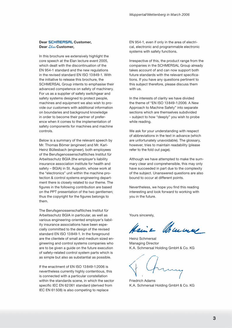
Performance level
instead of control category
The results of the analysis of 1 to 4 (i.e. the
analysis of designated architecture, channel
MTTFd, DC and CCF) are then entered onto a
block diagram, from which the performance
level attained can be read off (refer to Figure 8).
This means that a PL “e” requires a structure
corresponding to category 4, a channel MTTFd
value of “high” and an equally “high” DC (for
information on the DCavg
concept as cited).
If, on the other hand, the objective is for the
requisite risk reduction to achieve a PL “c” or
1) In der Systematik der Norm wird zwischen PLr und
PL unterschieden. PLr steht dabei für den aufgrund
der Risikobetrachtung benötigten Performance Level
(praktisch eine Soll-Ermittlung). PL ist dann das be-
wertete Ergebnis (praktisch die Ist-Ermittlung).
Pe
rfo
rma
nc
e le
vel
Category B
DCavg =0
Category 1
DCavg =0
Category 2
DCavg =low
Category 2
DCavg =medium
Category 3
DCavg =low
Category 3
DCavg =medium
Category 4
DCavg =high
a
b
c
d
e
MTTFd = lowMTTFd = mediumMTTFd = hoch
Figure 8: Simplifi ed determination of the Performance Level PL
“d”, several design possibilities may be se-
lected; for example for a PL “d” a structure in
accordance with category 2, a channel MTTFd
of “high” and a DC of “medium”. The CCF fac-
tor must always be considered from category
2 onwards.
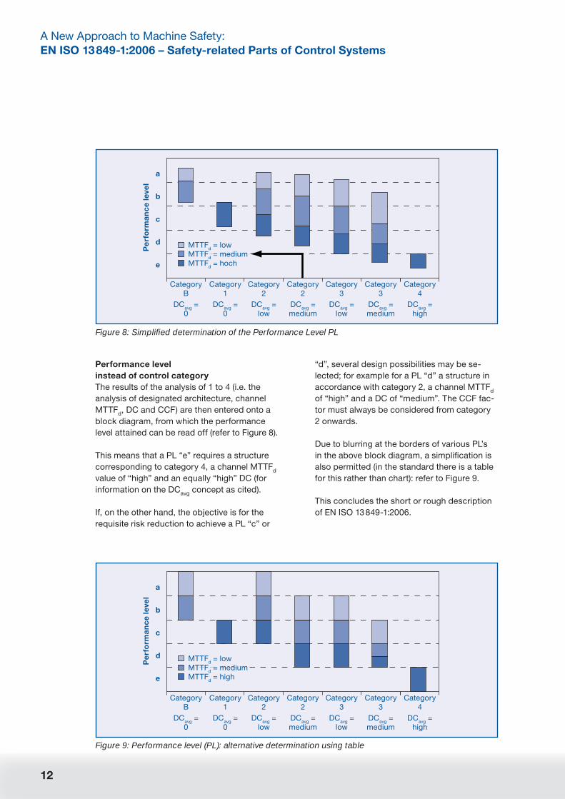
Due to blurring at the borders of various PL’s
in the above block diagram, a simplifi cation is
also permitted (in the standard there is a table
for this rather than chart): refer to Figure 9.
This concludes the short or rough description
of EN ISO 13 849-1:2006.
Figure 9: Performance level (PL): alternative determination using table
Pe
rfo
rma
nc
e le
vel
Category B
DCavg =0
Category 1
DCavg =0
Category2
DCavg =low
Category2
DCavg =medium
Category3
DCavg =low
Category3
DCavg =medium
Category4
DCavg =high
a
b
c
d
e
MTTFd = lowMTTFd = mediumMTTFd = high

13
Highrisk
Lowrisk
Starting pointto gauge
risk reduction
performance level PLr
Required
S1
S2
F1
F2
F1
F2
P1a
b
c
d
e
P2
P1
P2
P1
P2
P1
P2
Designated Architectures
Background
The familiar control categories are taken into
account in EN ISO 13 849-1:2006 via the so-
called designated architectures, which can
also be described as the advance calculation
of SRP/CS structures. Advance calculation
means that the contribution to risk reduction
that these structures effect within the frame-
work of the Markov modelling as seen in IEC
EN 61 508 has been previously tested, i.e. the
user of EN ISO 13 849-1:2006 no longer needs
to be concerned with these complex math-
ematical calculations.
Consideration of the designated architecture
of an SRP/CS updates the earlier deterministic
approach in EN 954-1. However, as already
described, it deals solely in the future with
one aspect among many which make up the
performance level.
If the designated architectures appear familiar
you are quite right. They basically deal with
nothing other than the familiar, established
tried and tested SRP/CS structures for the
various control categories which apply to the
application of EN 954-1. An exception to this
is, however, category 2 (as cited).
Execution
EN ISO 13 849-1:2006 thus recognises the des-
ignated architectures contained in Figure 10.
Application
The setting up of designated architectures
contributes to a positive development towards
simplifi cation in EN ISO 13 849-1:2006; howev-
er, some questions go unanswered (questions
which also remain unanswered when it comes
to the interpretation of EN 954-1).
These include, for example, the question of
how the 2-channel function is to be executed
at the sensor and actor level in categories 3
and 4. This means the sensor or actor func-
tions must physically be present twice, for
example in the form of two switches on the
position monitor of a moving protective device
and what action is necessary if one wishes to
deviate from the designated architectures.
Many alternatives may be considered:
Option 1 is based on the relevant C standard
(product standard) where there are precise
design suggestions. For example with a print-
ing and paper machine a single, but electrical
2-channel executed safety switch for the posi-
tion monitoring of a moving protective device
suffi ces.
Figure 10: Introduction to Designated Architectures
OL
Inputsignal
Outputsignal
I
OI L
Inputsignal
Outputsignal
OTETE
2ndswitch-off path
or indi-cation path
Monitoring
Mon
itorin
g
Mon
itorin
g
Monitoring
O1L1
Inputsignal
Outputsignal
Moni-toring
I1
O2L2Inputsignal
Outputsignal
Moni-toring
I2
Cro
ssm
onito
ring
Categories 3 and 4:Category 2:Categories B and 1:

14
A New Approach to Machine Safety:
EN ISO 13 849-1:2006 – Safety-related Parts of Control Systems
Option 2 operates using fault exclusion (refer
also to Figure 11), whereby as much atten-
tion should be paid to the practice of fault
exclusion as given to EN 954-1 until now. One
can either employ the fault exclusion lists in
accordance with Annexes A to D of EN ISO
13 849-2 (formerly EN 954-2) or conduct one’s
own analyses while adhering strictly to Section
3.3 of EN ISO 13 849-2.
Figure 11: Fault exclusions
When can I conduct a fault exclusion?
It is not always possible to evaluate a
SRP/Cs without assuming the exclusion of
certain faults. For detailed information on
fault exclusion refer to EN ISO 13 849-2. …
Fault exclusions may be based on:
• The technical improbability of the inci-
dence of certain faults
• The generally accepted technical experi-
ence, independent of application
• The technical demands regarding the
application and special hazards
When faults are excluded, a detailed ex-
planation must be provided in the docu-
mentation.
Option 3 is to put aside the simplifi cations in
EN ISO 13 849-1:2006 and instead perform
mathematical calculations using the Markov
modelling, Petri Nets or similar (or have them
performed) (refer also to Figure 12).
Figure 12: “No rules without exceptions”
Is it absolutely essential that I use des-
ignated architectures, or is it possible
without them?
4.5.1 … There are several methods to
make an estimation of the quantifi able
aspects of the PL for any type of sys-
tem (e.g. a complex structure). Methods
are e.g. Markov Modelling, Generalised
Stochastic Petri Nets (GSPN), Reliability
Block Diagrams [see e.g. EN 61508 (IEC
61 508) series].
To make easier the assessment of the
quantifi able aspects of this PL, this stan-
dard provides a simplifi ed method based
on the defi nition of fi ve designated archi-
tectures that fulfi l specifi c design criteria
and behaviour under fault condition.
CAUTION when using the designated archi-
tecture for category 2!
Although the description above states that the
so-called designated architectures are well-
known, there is here a serious exception, and
this is the recommended structure for control
category 2.
Here a considerable change will occur: where
control category 2 has up to now defi ned a
1-channel structure which must involuntarily
be tested at suitable intervals by the machine
controls, this will in future when used with des-
ignated architecture require a test frequency
100 times higher than the foreseeable demand
of the safety function and a second output
must be provided (refer also to Figure 13 on
Page 15).

15
Highrisk
Lowrisk
Starting pointto gauge
risk reduction
performance level PLr
Required
S1
S2
F1
F2
F1
F2
P1a
b
c
d
e
P2
P1
P2
P1
P2
P1
P2
Basically this designated architecture is like a
“light” control category 3 and when, at the end
of this report we attempt to summarise which
types of changes arise in practice following the
process of introducing EN ISO 13 849-1:2006,
then this summary should include an urgent
recommendation to test SRP/CS with control
category 2 in respect of the future altered
requirements.
MTTFd values
Background
Firstly in connection with the MTTFd consid-
erations of EN ISO 13 849-1:2006, and despite
often suppressing the thought, one must fi rst
be aware that SRP/CS also always still have a
residual safety-critical failure potential (namely
the failure potential of coincident hazardous
failures), thus the aim must be to control this
residual risk, i.e. to depress this to an accept-
able degree of residual risk.
For example, a switching contact cannot be
opened or closed. Generally not being able to
open with reference to a machine leads to a
hazardous state, if there is no redundancy or
timely fault identifi cation. But switching con-
tacts are not all the same. There are variances,
design differences, material differences etc.
One could also say quality differences exist
which can infl uence the probability of such
coincident failures.
This means that MTTFd is a quality statement
about the safety-related reliability of the safety
components deployed and the safety-oriented
devices in an SRP/CS.
By defi nition MTTFd is a statistical mean rep-
resenting the expected working time without
down time per annum (= MTTF), whereby in
EN ISO 13 849-1:2006 down times are only
considered when they indicate a hazardous
direction. This is the reason for the terminol-
ogy MTTFd (not every failure is a safety-critical
failure). Therefore the MTTFd value is always
> an MTTF value. The value is expressed in
years (= y).
An MTTFd value is thereby always the mirror
image (the reciprocal value) of the PFHd value
and vice versa. This means a MTTFd value of
10y, for example, equates to a PFHd value of
1.14 x 10⁻⁵ (1/10 x 8,760), however only with
reference to one channel¹.
With considerations of MTTF or MTTFd an
exponential distribution of coincident failure
is assumed, i.e. after the MTTF or MTTFd
sequence 63% of all (hazardous) units have
already failed and the probability of survival of
the relevant units considered after the MTTF or
MTTFd sequence only constitutes 37% (refer to
Figures 14 and 15).
OI L
Inputsignal
Outputsignal
OTETE
2ndswitch-off path
or indi-cation path
MonitoringM
onito
ring
Mon
itorin
gMonitoring
Category 2:
Figure 13: New requirements of control cat-egory 2
1) PFH values, which were calculated in accordance
with IEC EN 61 508, may be included in calculations
in accordance with EN ISO 13 849-1:2006 as long as
the SIL details are taken into account. This produces a
simplifi ed view – in particular for 2-channel structures
– but there is less risk of calculating methods which
“paint a rosy picture”.

16
A New Approach to Machine Safety:
EN ISO 13 849-1:2006 – Safety-related Parts of Control Systems
In other words:
Figure 14: Illustration of mean service life: three collectives with differing reliability levels are repre-sented. Their units (illustrated by the dots) fail at coincidental times. The vertical coordinates indicate their failure time. The failure times are spread over long time spans, e.g. in the case of the fi rst collective some individual units last for 18 years while others have already failed after one year. 63% have already failed after 6 years. (Source: introduction to the methods of reliability analysis, SIEMENS AG, 1&S IS ICS IT2)
Reliability distributionof units of three collectives
Intact
Failed
18years
37%63%
MTBF = 6 years MTBF = 18 years MTBF = 60 years
72%28%
90%10%
60years
Years
60
18
6
Figure 15: What does MTTFd exactly mean?
not accept-able
MTTFd =MTTFd =MTTFd =MTTFd =
3 y10 y30 y
100 y
Haz
ard
ous
failu
res
[%]
100%
80%
60%
40%
20%
0%0 5 10 15 20 25 30
Time [years]
not acceptable
low
medium
high
17
Highrisk
Lowrisk
Starting pointto gauge
risk reduction
performance level PLr
Required
S1
S2
F1
F2
F1
F2
P1a
b
c
d
e
P2
P1
P2
P1
P2
P1
P2
CAUTION: Exceptions to this assumed expo-
nential distribution which is typical of electron-
ics are components affected by wear and tear
which have a different lifetime distribution. This
factor applies to EN ISO 13 849-1:2006 via the
intermediate size of the so-called B10d
value
calculation (as cited).
Execution
In terms of EN ISO 13 849-1:2006, consider-
ations of MTTFd and PFH are to be differenti-
ated according to whether they are utilised
• for a single safety component
or
• for a single channel of an SRP/CS
or
• for a complete SRP/CS.
The above mentioned differentiation makes
sense only when considering the fact that a
large section of the clientele using EN ISO
13 849-1:2006 safety components and other
devices do not manufacture these themselves,
rather they purchase them and integrate them
into an SRP/CS.
In the future it will be easiest for this section
of EN ISO 13 849-1:2006 users, i.e. those who
purchase ready to use safety components, for
example from the product range of a com-
pany in the Schmersal Group, because it is
assumed that all well-known manufacturers
will include values in line with EN ISO 13 849-
1:2006 in their data sheets.
The purchaser of safety components can
justifi ably expect from his supplier that he has
these values ready on time, before EN ISO
13 849-1:2006 takes effect, i.e. with regard to
time this may not be here and now, but should
at least be expedient (refer here also to the
section “Enactment of EN ISO 13 849-1:2006”.
But others using components/devices can also
expect to be provided with fi gures from suppli-
ers, which within the strict terms of the EC ma-
chine directive (MRL) are not necessarily safety
components but rather dual-use products, i.e.
components/devices which can be deployed in
both safety-relevant and operational tasks.
CAUTION! If a fault exclusion is formulated for
a component, the MTTFd value in the relevant
formula is taken to be ∞ (as cited).
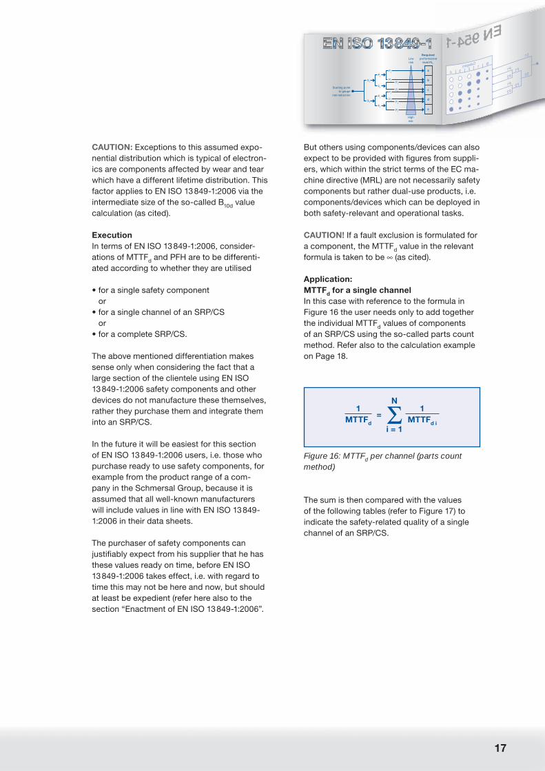
Application:
MTTFd for a single channel
In this case with reference to the formula in
Figure 16 the user needs only to add together
the individual MTTFd values of components
of an SRP/CS using the so-called parts count
method. Refer also to the calculation example
on Page 18.
Figure 16: MTTFd per channel (parts count method)
N1
= Σ 1
MTTFd
MTTFd i
i = 1
The sum is then compared with the values
of the following tables (refer to Figure 17) to
indicate the safety-related quality of a single
channel of an SRP/CS.

18
A New Approach to Machine Safety:
EN ISO 13 849-1:2006 – Safety-related Parts of Control Systems
In addition the following “rules” apply:
• MTTFd values always apply to one channel,
i.e. it is of no relevance whether we are deal-
ing with a 1 or 2-channel structure (desig-
nated architecture), unless the channels have
been differently (diversely) structured. In this
case a so-called symmetrisation formula ap-
plies (refer to Figure 18).
• The manufacturer (or person distributing
the machine) is responsible for calculating
(or having somebody calculate) the MTTFd
value of a channel within the terms of the EC
machine directive.
• CAUTION! If the calculation produces sev-
eral MTTFd values for a channel which are >
100 y, the excessive value is “cut off”, i.e. a
single SRP/CS channel may only have one
maximum MTTFd value of 100 y (in contrast
to a [safety] component which, looked at
in isolation, may well be higher). With this
restriction of 100 y, the standard-setter aims
to prevent the “painting of a rosy picture”
with regard to MTTFd values in order to at-
tain a higher performance level or enable
calculation methods to be used to substitute
1-channel structures when 2-channel struc-
tures are required.
Figure 17: MTTFd is a statistical mean value of operational time without dangerous failure in a single control channel
Description of quality Value range MTTFd
low 3 years ≤ MTTFd < 10 years
medium 10 years ≤ MTTFd < 30 years
high 30 years ≤ MTTFd ≤ 100 years
MTTFd is a statistical mean value and does not guarantee lifetime!
Calculation example
j Component Units
(nj)
MTTFd,j
worst case
[y]
1/MTTFd,j
worst case
[1/y]
nj/MTTFd,j
worst case
[1/y]
1 Transistors, Bipolar, low power 2 1142 0.000876 0.001752
2 Resistor, Carbon fi lm 5 11416 0.000088 0.000438
3 Capacitor, Standard, no power 4 5708 0.000175 0.000701
4 Relay (data from manufacturer) 4 1256 0.000796 0.003185
5 Contactor 1 32 0.031250 0.031250
Σ(nj/MTTF
d,j) 0.037325
MTTFd = 1/Σ(n
j/MTTF
d,j) [y] 26.79
This example gives a MTTFd of 26.8 years, which is "medium" according to fi gure 17.
In this example the main infl uence comes from the contactor. In general the result will be much
better, that is, a higher MTTFd.

19
Highrisk
Lowrisk
Starting pointto gauge
risk reduction
performance level PLr
Required
S1
S2
F1
F2
F1
F2
P1a
b
c
d
e
P2
P1
P2
P1
P2
P1
P2
• CAUTION! The merging of the single safety-
oriented devices to one SPP/CS is condi-
tional upon the following:
• that the application takes place under strict
consideration of any information in the
relevant user instructions and
• additional fault exclusions are guaranteed–
particularly with reference to electrical wir-
ing – in accordance with ISO 13849-2 (as
cited).
• Where software is involved, the additional
requirements of EN ISO 13 849-1:2006 apply
(refer to Section 4.6).
• The so-called symmetrising formula takes ef-
fect if two channels of an SRP/CS have been
differently structured (refer to Figure 18).
Remarks
• If individual components or devices which
are designed for an SRP/CS lend themselves
to IEC EN 61 508 (or IEC EN 62 061) oriented
manufacturers, then in general a so-called
Lambda value (λ) is given. This value in terms
of prEN IO 13 849-1 can be equated with a
PFHd value.
If, however, one wants or has to roam be-
tween the “worlds” of EN ISO 13 849-1:2006
and IEC EN 61 508 (or IEC EN 62 061) for
safety components and safety-oriented
devices (refer here also to Page 44), then we
recommend that this is done via the perfor-
mance or SIL level.
• If only one MTTF value is available (i.e.
no MTTFd value), the MTTF value may be
doubled (under the assumption that danger-
ous and harmless failures are roughly evenly
balanced) in order to arrive at an MTTFd
value. EN ISO 13 849-1:2006 furthermore
recommends that when in doubt let only one
part (suggestion is 10%) fl ow into the calcu-
lation, in order to err on the side of caution.
• If only one MTBF value is available, to sim-
plify matters one can usually treat it as an
MTTF value.
Application: MTTFd calculation for a single
safety-oriented device
This applies to those building safety-oriented
devices, control systems as well as dual-use
products for their own use. For them the rule
is to break down relevant safety-oriented
equipment into its functional components and
– again likewise – to calculate the MTTFd value
using the so-called parts count method (as
cited).
Here, too, EN ISO 13 849-1:2006 offers help
in the event that no MTTF or MTTFd value of
one’s own is available, by providing typical
values in the standard in the tables in an-
nex C for individual electrical and electronic
components (refer to Figure 19). Further works
of reference are, for example, the SN 29 500
standard or MIL hand books.
Figure 18: Differing MTTFd per channel –> symmetrisation
• The designated architectures assume the same MTTFd for both channels.
• Symmetrisation formulae for differing MTTFd values:
MTTFd =
2MTTF
d C1 + MTTF
d C2 –
1
3 1+
1
MTTFd C1
MTTFd C2
• Example: MTTFd C1
= 3 years, MTTFd C3
= 100 years leading to MTTFd = 66 years
20
A New Approach to Machine Safety:
EN ISO 13 849-1:2006 – Safety-related Parts of Control Systems
Components/devices affected by wear and
tear in an SRP/CS receive especial consider-
ation in EN ISO 13 849-1:2006, because here
the demand (namely the demand mode) has a
substantial bearing on the MTTFd value.
Only electronic components and safety-rel-
evant devices have a direct MTTFd value,
because here the so-called bath curve can
be referred to as an indicator of failures which
are independent of wear and tear. Both the
left part (keyword: early failures) and the right
part of the bath curve are disregarded. The left
part is disregarded because any early failures
will have been addressed through appropriate
measures by the manufacturer, such as artifi -
cial aging. The right part is excluded because
it is assumed that it lies far beyond the actual
duration of use.
B10d
values
There are intermediate sizes for an MTTFd con-
version, the fi rst of which being the B10d
value,
used with components affected by wear and
tear, such as for example electromechanical or
fl uidic devices as well as mechanical compo-
nents. This value is equivalent to a kind of op-
erating cycle capacity, whereby safety-related
function is deemed tolerable when considered
using the Weibull approach.
The B10d
value is converted bearing in mind
the application conditions, i.e. considering the
duration of use and the mean demand mode of
the safety function of the relevant component
in an MTTFd value (refer to Figure 20).
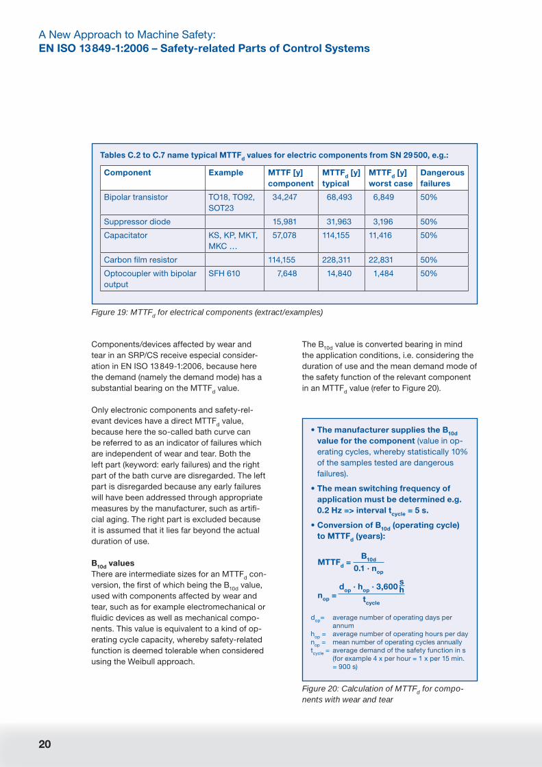
Figure 19: MTTFd for electrical components (extract/examples)
Tables C.2 to C.7 name typical MTTFd values for electric components from SN 29 500, e.g.:
Component Example MTTF [y]
component
MTTFd [y]
typical
MTTFd [y]
worst case
Dangerous
failures
Bipolar transistor TO18, TO92,
SOT23
34,247 68,493 6,849 50%
Suppressor diode 15,981 31,963 3,196 50%
Capacitator KS, KP, MKT,
MKC …
57,078 114,155 11,416 50%
Carbon fi lm resistor 114,155 228,311 22,831 50%
Optocoupler with bipolar
output
SFH 610 7,648 14,840 1,484 50%
Figure 20: Calculation of MTTFd for compo-nents with wear and tear
• The manufacturer supplies the B10d
value for the component (value in op-
erating cycles, whereby statistically 10%
of the samples tested are dangerous
failures).
• The mean switching frequency of
application must be determined e.g.
0.2 Hz => interval tcycle
= 5 s.
• Conversion of B10d
(operating cycle)
to MTTFd (years):
MTTFd =
B10d
0.1 · nop
dop
· hop
· 3,600s
nop
=h
tcycle
dop
= average number of operating days per
annum
hop
= average number of operating hours per day
nop
= mean number of operating cycles annually
tcycle
= average demand of the safety function in s
(for example 4 x per hour = 1 x per 15 min.
= 900 s)

21
Highrisk
Lowrisk
Starting pointto gauge
risk reduction
performance level PLr
Required
S1
S2
F1
F2
F1
F2
P1a
b
c
d
e
P2
P1
P2
P1
P2
P1
P2
In addition (refer to Figure 21) prEN ISO
13 849-1 offers recommendations for deciding
which B10d
values to adopt for typical devices
affected by wear and tear should no indica-
tions be given by the manufacturer.
These are differentiated according to whether
the respective device is operated at “full load”
or lower (for example in respect of contactors
and relays). Here “full load” is not only meant
in the electrical sense, but also for example in
the sense of particularly unfavourable envi-
ronmental operating conditions, i.e. marginal
operating conditions in general.
The scale for small load is defi ned in the stan-
dard as 20%, however the representation of
intermediate values – although not linear – may
be “allowed”, for example (at 20.0 million op-
erating cycles and 20%) 7.5 million operating
cycles at 40%, 2.5 million operating cycles at
60% and 1.0 million operating cycles at 80%.
Figure 21: B10d values (extract) in accordance with standard
Mechanical components MTTFd = 150 years
Hydraulic components MTTFd = 150 years
Pneumatic components B10d
= 20,000,000
Relays/contactors (with small load) B10d
= 20,000,000
Relays/contactors (with maximum load) B10d
= 400,000
Main contactor (small load) B10d
= 20,000,000
Main contactor (maximum load) B10d
= 2,000,000
Emergency stop device B10d
= 10,000
Control device (push button) B10d
= 100,000
Factor of 50
Figure 22: Converted MTTFd for pneumatic and electromechanical components depending on the demand mode (tcycle)
tcycle
= 24 h 1 h 1 min. 1 sec.
Pneumatic components 547,945 22,831 380 6.3
Relay/contactors (small load) 547,945 22,831 380 6.3
Relay/contactors (maximum load) 10,960 457 7.6 0.1
Main contactor (with small load) 547,945 22,831 380 6.3
Main contactor (with maximum load) 54,794 2,283 38 0.6
Emergency stop device 274 11 0.2 0.003
Control device (push button) 2,739 114 1.9 0.032
MTTFd > 100 years
22
A New Approach to Machine Safety:
EN ISO 13 849-1:2006 – Safety-related Parts of Control Systems
There is an exception for mechanical and
hydraulic components that deviate from the
calculation loop. Here the standard-setter has
determined MTTFd values of 150 y unaffected
by demand mode on the base of empirical
tests¹.
Figure 22 shows a conversion example of B10d
values into MTTFd values based on diverse
demand modes (1 x per 24 hours, 1 x per hour
etc) (whereby this assumes a 24 hour opera-
tion on 365 days of the year).
T10d
values
CAUTION! The so-called T10d
value, which is
derived from consideration of the B10d
value,
is also in the EN ISO 13 849-1:2006, and this
corresponds to 10% of the calculated MTTFd
value. In connection with this comes the
recommendation that safety-oriented devices
and other safety-relevant devices should be
replaced when they reach the T10d
value as a
precautionary measure.
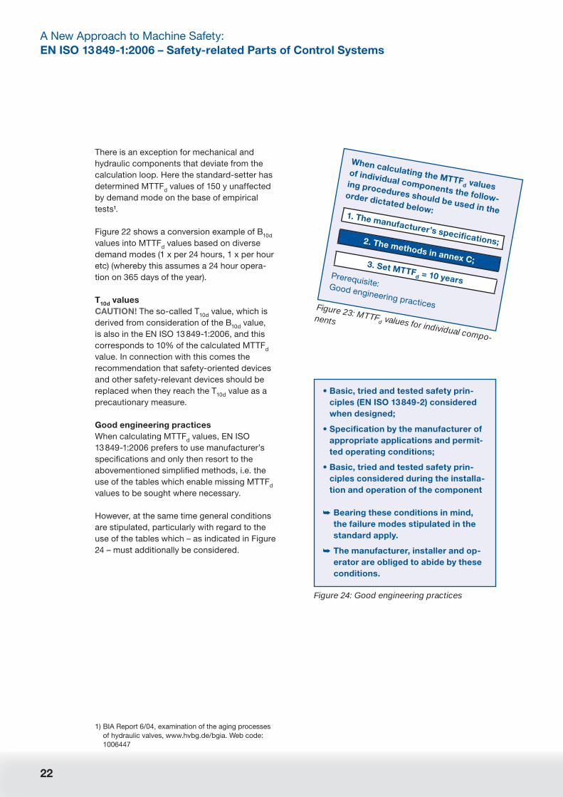
Good engineering practices
When calculating MTTFd values, EN ISO
13 849-1:2006 prefers to use manufacturer’s
specifi cations and only then resort to the
abovementioned simplifi ed methods, i.e. the
use of the tables which enable missing MTTFd
values to be sought where necessary.
However, at the same time general conditions
are stipulated, particularly with regard to the
use of the tables which – as indicated in Figure
24 – must additionally be considered.
Figure 23: MTTFd values for individual compo-
nents
When calculating the MTTFd values
of individual components the follow-
ing procedures should be used in the
order dictated below:1. The manufacturer’s specifi cations;
The manufacturer’s specifi cations;2. The methods in annex C;3. Set MTTF
d = 10 yearsPrerequisite: Good engineering practices
Figure 24: Good engineering practices
• Basic, tried and tested safety prin-
ciples (EN ISO 13 849-2) considered
when designed;
• Specifi cation by the manufacturer of
appropriate applications and permit-
ted operating conditions;
• Basic, tried and tested safety prin-
ciples considered during the installa-
tion and operation of the component
➥ Bearing these conditions in mind,
the failure modes stipulated in the
standard apply.
➥ The manufacturer, installer and op-
erator are obliged to abide by these
conditions.
1) BIA Report 6/04, examination of the aging processes
of hydraulic valves, www.hvbg.de/bgia. Web code:
1006447

23
Highrisk
Lowrisk
Starting pointto gauge
risk reduction
performance level PLr
Required
S1
S2
F1
F2
F1
F2
P1a
b
c
d
e
P2
P1
P2
P1
P2
P1
P2
Diagnostic coverage
Background
While the requirements in EN ISO 13 849-
1:2006 in respect of MTTFd calculations
remain, in spite of everything, relatively easy
to understand and straightforward (once the
mental hurdle of the probability consideration
and the search for the values has carefully
and successfully been completed), some al-
lowances must be made when examining the
so-called diagnostic coverage (DC).
This is concerned with the ratio of detected
dangerous failures to the failure mode of all
dangerous failures and the quantifi cation of
the effi cacy of measures to uncover failures in
an SRP/CS.
This assumes that (a) failures can occur (see
MTTFd) and (b) that mechanisms for detect-
ing such failures – also when accounting for
the timeline – are not equally effective and
that there is even a proportion of undetected
failures.
This too is apparent, particularly because not
every failure in an SRP/CS can be immediately
detected, but sometimes is only noticed when
the safety function is next demanded; for
example, when opening a moving protective
device one thinks of a bridged electromechani-
cal safety contact or a welded relay.
Figure 25: Diagnostic coverage DC
DC =Failure mode of detected dangerous failures
Failure mode of all dangerous failures+
dd
dd du
sdd
du
Identifi cation of all online tests and monitoring measures
DC values for every
test measure from
a table
EN ISO 13 849-1:2006,
Annex E
IEC 61 508-2, Table A.2-15
CP U1
CP U2 A2
M1
M2
A1
S2
S1
CPU2
CPU1
90%0%
90%
90%
90%
90%
60%
90%
90%
99%
99%
99%
99%
99%
Intakt
Figure 26: Determination of the average DC for the total system, Part 1

24
A New Approach to Machine Safety:
EN ISO 13 849-1:2006 – Safety-related Parts of Control Systems
The subject of “failure recognition” is of
particular signifi cance from a safety-relevant
point of view, notably to avoid so-called fault
accumulation. This means avoiding a situation
whereby one remaining undetected fault in an
SRP/CS is joined by a second fault (a so-called
second fault) which would make the safety
function obsolete.
When one considers empirical examinations
which show that a simple redundant system
with fault detection has a better safety per-
formance than a multiply redundant system
without fault detection, this plainly illustrates
the particular importance of the quality of fault
detection – apart from the fact that they are
cost effective.
Execution
In the interests of simplicity, EN ISO 13 849-
1:2006 also divides the quality of fault detec-
tion (the so-called diagnostic coverage) into
steps (refer to Figure 27).
With annex E, EN ISO 13 849-1:2006 offers
further simplifi cation still (refer to Page 25).
Determination of the average DC for the total system
using an approximation formula:
Denotation Range of DC
none DC < 60%
low 60% ≤ DC < 90%
medium 90% ≤ DC < 99%
high 99% ≤ DC
PL
Figure 27: Determination of the average DC for the total system, Part 2
Figure 29: Examples for coverage
Measure DC
Relay/
contactor
Plausibility test, e.g. application of positively
driven NO and NC contacts
99%
Actor Monitoring of outputs via 2-channels with-
out dynamic tests
0–99% depending on the signal
changes in the application
Sensor Monitoring of certain properties (reaction
time, area of analogue signals, e.g. electric
resistors, capacity)
60%
Logic Self-testing using software 60–90%
Formula in the standard
for DCavg
in accordance
with Figure 28

25
Highrisk
Lowrisk
Starting pointto gauge
risk reduction
performance level PLr
Required
S1
S2
F1
F2
F1
F2
P1a
b
c
d
e
P2
P1
P2
P1
P2
P1
P2
Figure 28: Average diagnostic coverage DCavg
• Only an average value for DCavg
enters the PL, which must be weighted across all tests.
• Weighting factor is the MTTFd of the tested parts:
DCavg
=
DC1 +
DC2 + ... +
DCS
MTTFd1
MTTFd2
MTTFdN
1+
1+ ... +
1
MTTFd1
MTTFd2
MTTFdN
• Untested parts are entered as DC = 0. All parts which cannot demonstrate a fault exclu-
sion enter the sum (fault exclusion => MTTFd = ∞).
Application
An average value DCavg
is calculated which
refl ects the fault detection quality of all parts of
each channel.
The MTTFd values of the safety-oriented com-
ponents/devices which go to make an SRP/CS
channel fl ow into the consideration in so far as
a combination of a “bad” MTTFd and a “bad”
single DC are more heavily weighted, thus the
DCavg
is forced down (and vice versa).
This inductive approach when calculating the
fault detection mode DCavg
may make sense.
Nevertheless it does not exactly serve the
interests of simplifi cation, even if there is a
comprehensive look-up table in annex E of EN
ISO 13 849-1:2006.
A multitude of diverse tried and tested mea-
sures for fault detection with a DC evaluations
as a percentage are listed in annex E, but there
are some occasions where the evaluation of
a measure in the table is given as “0 … 99%
depending on …” which leaves a great deal
of leeway – something which EN ISO 13 849-
1:2006 actually seeks to avoid and which seri-
ously requires greater analysis, as has been
the case with IEC EN 61 508.
26
A New Approach to Machine Safety:
EN ISO 13 849-1:2006 – Safety-related Parts of Control Systems
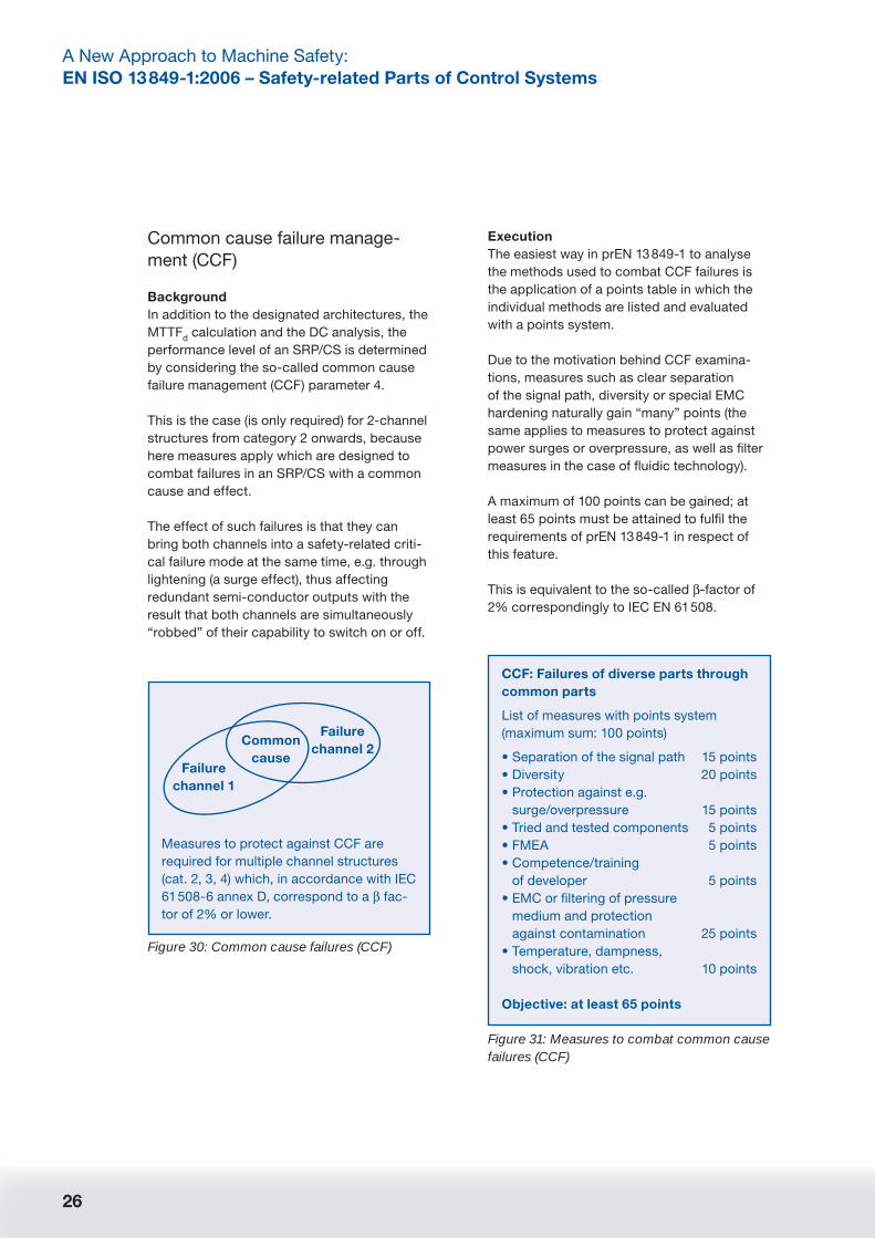
Figure 30: Common cause failures (CCF)
Measures to protect against CCF are
required for multiple channel structures
(cat. 2, 3, 4) which, in accordance with IEC
61 508-6 annex D, correspond to a β fac-
tor of 2% or lower.
Failure
channel 1
Common
cause
Failure
channel 2
Common cause failure manage-
ment (CCF)
Background
In addition to the designated architectures, the
MTTFd calculation and the DC analysis, the
performance level of an SRP/CS is determined
by considering the so-called common cause
failure management (CCF) parameter 4.
This is the case (is only required) for 2-channel
structures from category 2 onwards, because
here measures apply which are designed to
combat failures in an SRP/CS with a common
cause and effect.
The effect of such failures is that they can
bring both channels into a safety-related criti-
cal failure mode at the same time, e.g. through
lightening (a surge effect), thus affecting
redundant semi-conductor outputs with the
result that both channels are simultaneously
“robbed” of their capability to switch on or off.
Execution
The easiest way in prEN 13 849-1 to analyse
the methods used to combat CCF failures is
the application of a points table in which the
individual methods are listed and evaluated
with a points system.
Due to the motivation behind CCF examina-
tions, measures such as clear separation
of the signal path, diversity or special EMC
hardening naturally gain “many” points (the
same applies to measures to protect against
power surges or overpressure, as well as fi lter
measures in the case of fl uidic technology).
A maximum of 100 points can be gained; at
least 65 points must be attained to fulfi l the
requirements of prEN 13 849-1 in respect of
this feature.
This is equivalent to the so-called β-factor of
2% correspondingly to IEC EN 61 508.
Figure 31: Measures to combat common cause failures (CCF)
CCF: Failures of diverse parts through
common parts
List of measures with points system
(maximum sum: 100 points)
• Separation of the signal path 15 points
• Diversity 20 points
• Protection against e.g.
surge/overpressure 15 points
• Tried and tested components 5 points
• FMEA 5 points
• Competence/training
of developer 5 points
• EMC or fi ltering of pressure
medium and protection
against contamination 25 points
• Temperature, dampness,
shock, vibration etc. 10 points
Objective: at least 65 points
27
Highrisk
Lowrisk
Starting pointto gauge
risk reduction
performance level PLr
Required
S1
S2
F1
F2
F1
F2
P1a
b
c
d
e
P2
P1
P2
P1
P2
P1
P2
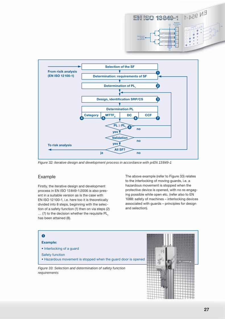
Figure 32: Iterative design and development process in accordance with prEN 13 849-1
From risik analysis(EN ISO 12100-1)
To risk analysis
ja
yes
yes
no
no
no
Selection of the SF
Determination: requirements of SF
Determination of PLr
Design, identification SRP/CS
Determination PL
PL PLr
Category MTTFd DC CCF
Validation
All SF?
1
2
3
7654
8
➊
Example:
• Interlocking of a guard
Safety function
• Hazardous movement is stopped when the guard door is opened
Figure 33: Selection and determination of safety function requirements
Example
Firstly, the iterative design and development
process in EN ISO 13 849-1:2006 is also pres-
ent in a suitable version as is the case with
EN ISO 12 100-1, i.e. here too it is theoretically
divided into 8 steps, beginning with the selec-
tion of a safety function (1) then on via steps (2)
… (7) to the decision whether the requisite PLr
has been attained (8).
The above example (refer to Figure 33) relates
to the interlocking of moving guards, i.e. a
hazardous movement is stopped when the
protective device is opened, with no re-engag-
ing possible while open etc. (refer also to EN
1088: safety of machines – interlocking devices
associated with guards – principles for design
and selection).
28
A New Approach to Machine Safety:
EN ISO 13 849-1:2006 – Safety-related Parts of Control Systems
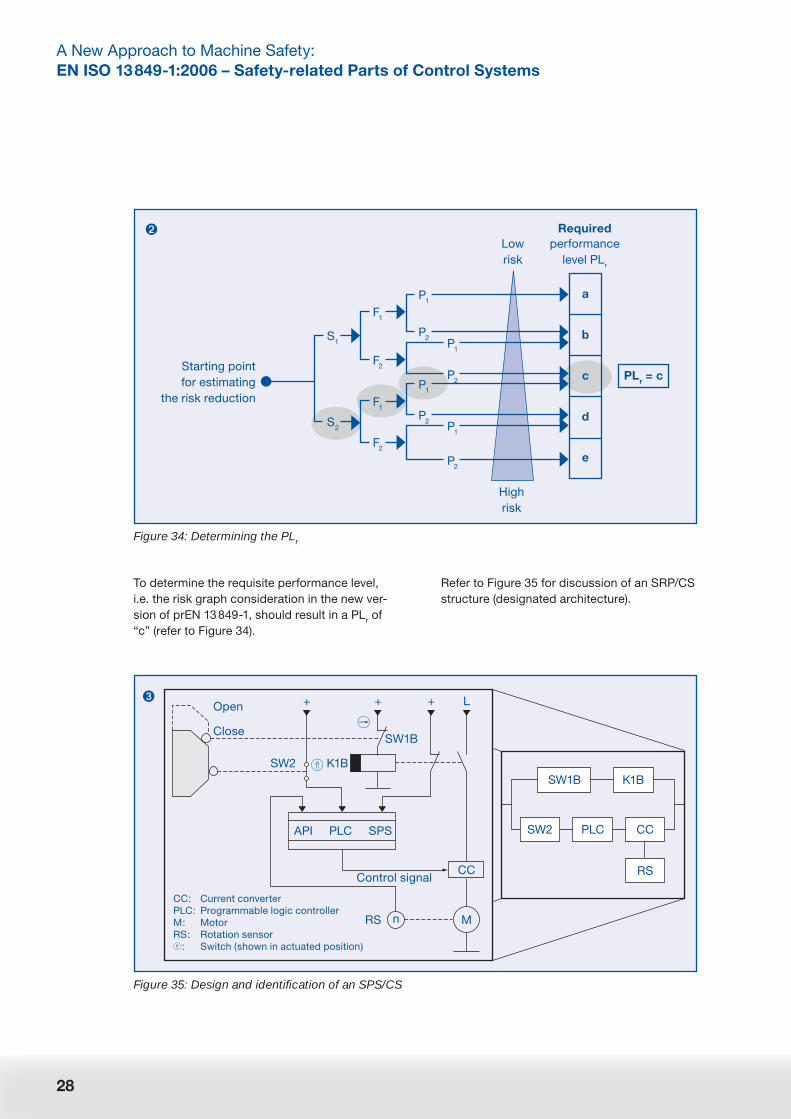
To determine the requisite performance level,
i.e. the risk graph consideration in the new ver-
sion of prEN 13 849-1, should result in a PLr of
“c” (refer to Figure 34).
Refer to Figure 35 for discussion of an SRP/CS
structure (designated architecture).
Highrisk
Lowrisk
Starting pointfor estimating
the risk reduction
performance level PLr
Required
PLr = c
S1
S2
F1
F2
F1
F2
P1a
b
c
d
e
P2
P1
P2
P1
P2
P1
P2
Figure 34: Determining the PLr
➋
SW1B
K1BSW2
CC:PLC:M:RS:
:
Current converterProgrammable logic controllerMotorRotation sensorSwitch (shown in actuated position)
Close
Open
Control signalCC
L+++
MRS n
API PLC SPS
SW1B K1B
SW2 PLC CC
RS
Figure 35: Design and identifi cation of an SPS/CS
➌

29
Highrisk
Lowrisk
Starting pointto gauge
risk reduction
performance level PLr
Required
S1
S2
F1
F2
F1
F2
P1a
b
c
d
e
P2
P1
P2
P1
P2
P1
P2
Because both channels in the example are
constructed differently (refer to the SRP/CS
structure), differing MTTFd values for the two
channels A and B must fi rst be determined and
symmetrised with each other.
➍
• Fulfi lls the requirements
of category B ✔
• Single failure do not lead
to loss of SF? ✔
• Partial fault detection ✔
• An accumulation of undetected
faults does not lead to loss of the SF?
(1st SPS fails without being detected,
2nd channel A fails) ✔
–> Category 3 can be achieved
Figure 36: Determination of the PL category
Based on the designated architecture in ac-
cordance with Figure 35 this means:
➎
• SW1B: positive opening contact:
Fault exclusion for non-opening of the
contacts, non-activation of the switches
due to mechanical failure (e.g. plunger
break, wear and tear of actuating lever,
misalignment)
• K1B: MTTFd = 30 y
(manufacturer’s specifi cation)
1 = 1 = 1
MTTFd C1
MTTFd K1B
30 y
Channel 1: MTTFd = 30 y
Figure 37: Determination of the PL: MTTFd for channel A
Below is an analysis of the diagnostic cover-
age (DC):
➎
• SW2, SPS, CC:
MTTFd = 20 y each (manufacturer’s specifi cation)
1 = 1 + 1 + 1 = 3
MTTFd C2
MTTFSW2
MTTFPLC
MTTFCC
20 y
Channel 2: MTTFd = 6.7 y
• MTTFd symmetrised for both channels:
MTTFd =
2MTTF
d C1 + MTTF
d C2 –
1
3 1+
1
MTTFd C1
MTTFd C2
MTTFd = 20 y (medium)
Figure 38: Determination of the PL: MTTFd for channel B and total MTTFd
Figure 39: Determination of the PL: DCavg
➏
• DCK1B
= 99%, “high” due to the positively driven electric
contacts from the table in annex E.1
• DCSW2
= 60%, “low” due to the monitoring of the entry
signals without dynamic tests
• DCPLC
= 30%, “none” due to the low effectiveness of the
self-tests
• DCCC
= 90%, “medium” due to the reduced switch off
distance with actor monitoring by the controller, refer to
table in E.1 from table in annex E.1
DCavg
=
DC1 +
DC2 + ... +
DCS
MTTFd1
MTTFd2
MTTFdN
1+
1+ ... +
1
MTTFd1
MTTFd2
MTTFdN
DCavg
= 67% (low)

30
A New Approach to Machine Safety:
EN ISO 13 849-1:2006 – Safety-related Parts of Control Systems
Below is the determination of the CCF man-
agement:
Figure 40: Determination of the PL: CCF
➐
CCF: Failures of various parts through
common causes
• Separation of the signal paths 15 points
• Diversity 20 points
• Protection against e.g.
surge/overpressure 0 points
• Tried and tested components 5 points
• FMEA 5 points
• Competence/training
of the developer 0 points
• EMC or fi ltering of the
pressure medium and pro-
tection against contamination 25 points
• Temperature, dampness,
shock, vibration etc. 10 points
Σ = 80 points > 65 points
… and – fi nally – the arrangement in the block
diagram, i.e. the verifi cation whether PL => PLr
(refer to Figure 41).
Remarks: Remarks: naturally the meticulous
breakdown in the individual stages of the
above example has been somewhat exagger-
ated. Furthermore the example illustrates two
differing constructed channels on both the
sensor side and logic side, and it thus looks
rather more complex than those frequently
used in practice.
Nevertheless: this demonstrates the thoughts
behind the new requirements of EN ISO
13 849-1:2006, although in the example no
B10d
value consideration was employed for the
interlocking device (as an electromechanical
device) – which would actually be (more) ac-
curate.
Pe
rfo
rma
nc
e le
vel
Category B
DCavg =0
Category1
DCavg =0
Category2
DCavg =low
Category2
DCavg =medium
Category3
DCavg =low
Category3
DCavg =medium
Category4
DCavg =high
a
b
c
d
e
MTTFd = lowMTTFd = mediumMTTFd = high
Figure 41: Verifi cation of whether PL ≥ PLr has been achieved
➑
PL = PLr = c ✔
31
Highrisk
Lowrisk
Starting pointto gauge
risk reduction
performance level PLr
Required
S1
S2
F1
F2
F1
F2
P1a
b
c
d
e
P2
P1
P2
P1
P2
P1
P2
In the example the risk graph assumption F1
would however no longer hold (see above:
exposition of hazards seldom to more often
and/or short exposition duration). Rather F2
should be assumed, and with it the required
performance level “d”. Thanks to the corrected
and “good” MTTFd value however this too
poses no problem.
Editorial remark:
The necessary correction loop in the above
example shows that the setting of standards
is also an iterative process, for the example
actually stems from the standard although it
was created at a point in time when B10d
value
considerations had not yet been included. But
B10d
value considerations are the very ones
which for the user constitute a fundamentally
signifi cant part of the standard. Without them
prEN 13 849-1 would have problems justifying
its specifi c requirements with regard to actual
practicability.
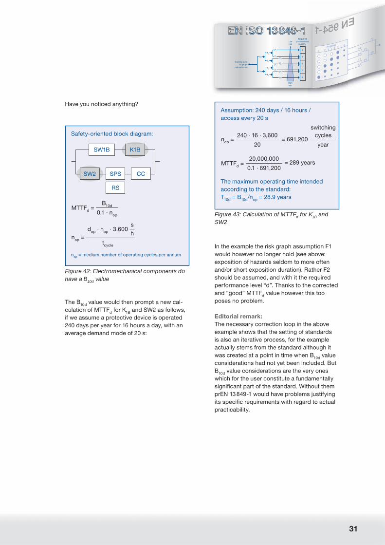
Figure 42: Electromechanical components do have a B10d value
Safety-oriented block diagram:
MTTFd =
B10d
0,1 · nop
dop
· hop
· 3.600s
nop
=h
tcycle
nop
= medium number of operating cycles per annum
SW1B K1B
SW2 SPS
RS
CC
Figure 43: Calculation of MTTFd for K1B and SW2
Assumption: 240 days / 16 hours /
access every 20 s
nop
=240 · 16 · 3,600
= 691,200
switching
cycles
20 year
MTTFd =
20,000,000= 289 years
0.1 · 691,200
The maximum operating time intended
according to the standard:
T10d
= B10d
/nop
= 28.9 years
The B10d
value would then prompt a new cal-
culation of MTTFd for K
1B and SW2 as follows,
if we assume a protective device is operated
240 days per year for 16 hours a day, with an
average demand mode of 20 s:
Have you noticed anything?

32
A New Approach to Machine Safety:
EN ISO 13 849-1:2006 – Safety-related Parts of Control Systems
Validation1
Subsequently, the validation follows in ac-
cordance with EN ISO 13 849-2, but this will
not be examined in detail here as the con-
siderations to be followed must already be
observed today.
Product specification
Plan
Protocol/reports
Tests
Fault lists(3.2, 3.3)
Validation guidelines (3.1)
Validation plan (3.4)
Start
Yes
Yes
No
No
Consideration during design
(EN 954-1: 1996, section 4)
Fault exclusioncriteria
(refer to appropriate annex)
Is ana-lysis ade-
quate?
Documents(3.5)
End
Analysis(section 4)
Test(section 5)
Testcomplete?
Validation report(3.6)
Figure 44: Validation plan in accordance with EN ISO 13 849-2
1) There is no detailed examination here of measures to
combat systematic failure because these too already
form part of the total requirements of SRP/CS. A
detailed representation can be found in annex G of EN
ISO 13 849-1:2006.
EN ISO 13 849-2 is concerned with content
originally planned for the EN 954-2 standard
which – once passed – was, however directly
transferred to the ISO level. But a revision is
expected here sooner or later in order to align
editing as of 1998/1999 and references to
EN 954-1 with the current state of affairs – in
other words EN ISO 13 849-1:2006.

33
Highrisk
Lowrisk
Starting pointto gauge
risk reduction
performance level PLr
Required
S1
S2
F1
F2
F1
F2
P1a
b
c
d
e
P2
P1
P2
P1
P2
P1
P2
Nevertheless: when one considers that the
majority of machine accidents cannot be
attributed to coincident failures, but can be
linked to specifi cation faults and subsequent
alignments and alterations, then the subject
of validation is the very one that is of major
signifi cance to the safety of a machine.
In addition the informative annexes from EN
ISO 13 849-2 play an important role in connec-
tion with EN ISO 13 849-1:2006. The annexes
– which are split into the technologies of
mechanics (annex A), pneumatics (Annex B),
hydraulics (Annex C) and electrics (Annex D)
– consist of the following lists:
• Fundamental safety principles (important for
EN 954-1 control category B and PL “a”);
• Tried and tested safety principles (important
for EN 954-1 control category 1 et seq. and
PL “b” … PL “e”);
• Safety-related tried and tested components
(important for EN 954-1 control category 1
and PL “b”);
• And lists of applicable faults and permis-
sible fault exclusions (important for EN 954-1
control categories 2, 3 and 4 and PL “c” …
PL “e”).

34
A New Approach to Machine Safety:
EN ISO 13 849-1:2006 – Safety-related Parts of Control Systems
SiSteMa
The answer to the obvious question which
arises at this juncture, i.e. whether the exem-
plary procedures introduced above could not
be enormously simplifi ed through the use of
software, is that this is now surely only a ques-
tion of time.
The BGIA for example is working on software
called SiSteMa (safety of machine controls)
which at will be available as freeware in due
course.

35
Highrisk
Lowrisk
Starting pointto gauge
risk reduction
performance level PLr
Required
S1
S2
F1
F2
F1
F2
P1a
b
c
d
e
P2
P1
P2
P1
P2
P1
P2
Although SiSteMa is not yet available (avail-
ability is planned from the middle of 2006),
support with regard to dealing with EN ISO
13 849-1:2006 is already being provided by
the employer’s liability insurance association.
This is in the form of a so-called PLC disc
which facilitates the simple determination of
the performance level, and which has been
developed with the support of the Zentral-
verband Elektrotechnik- und Elektroindustrie
(ZVEI) – Fachverband Automation (the Ger-
man central association for electrotechnol-
ogy and the electrical industry – professional
association for automation) and the Verband
Deutscher Maschinen- und Anlagenbau
VDMA (the German mechanical engineering/
capital goods manufacturers’ association).
The methods of prEN 13 849-1 are made
comprehensible through the use of two
discs which rotate against one another. The
performance level (PL) is determined simply
by twisting one disc until the desired value of
MTTFd (mean time to dangerous failure) ap-
pears in the lower window.
Then the desired category and diagnostic
coverage (DC) must merely be selected in the
upper window and the numerical value which
appears in the window next to it read off. The
mean time to dangerous failure of the safety-
related control system is produced by multi-
plying this by a factor represented in the key
(order of magnitude). The colour code serves
the selection of the factor and simultaneously
indicates which PL has been achieved.
PLC reference source:
www.hvbg.de/e/bia/pra/drehscheibe.html

36
A New Approach to Machine Safety:
EN ISO 13 849-1:2006 – Safety-related Parts of Control Systems
EN ISO 13 849-1:2006
and straightforward SRP/CS
Background
When we know the relevant performance levels
for the safety-oriented devices implemented
we are able to discern the manageable com-
plexity in EN ISO 13 849-1:2006 for SRP/CS,
arising from its singular concept of simplifi ca-
tion.
At the same time this procedure also refl ects
the fact that the linking of a greater number of
safety components and other safety-oriented
devices can affect the overall PL, i.e. that the
overall PL of a complete control system (con-
sisting of several series connected SRP/CS)
can very well turn out to be lower than indi-
vidual PL’s and the “chain links” involved. The
idea behind this thought, and one which is also
evident, is that in this case the probability of
so “many” residual failures adds up, so that
the overall PL can very well be lowered by one
step.
Design
The above mentioned consideration in favour
of simplifi cation is rediscovered in the table
seen in Figure 45 (which is also known as the
combination table), in which the number of
individual PL’s in a control system can be read
off on the left-hand section, whereby the low-
est PL’s should be added together here, and
then the overall PL read off on the right-hand
side.
As a rule (when dealing with “more simple”
structures”) more than three identical single
PL’s and more than four identical single PL’s
(when it comes to fully-fl edged 2-channel
structures) sink the overall PL by one step, i.e.
3 x one single PL “c” produce an overall PL
of “b”, or 4 x one single PL of the type “e” an
overall PL of “d”.
The following example (refer to Figure 45)
shows that this means the two lowest single
PL’s are to be added together (2 x PL “c”,
whereas the one higher PL “d” is not included
in the calculation (PL “d” is viewed as an order
of magnitude better than PL “c” with regard to
the PFH value). 2 x PL “c” therefore remain as
PL “c”. If, however, a PL “c” could be account-
ed for here (instead of the 1 x PL “d”), this
would (only) produce an overall PL of “b”.
Figure 45: Linear combination of multiple SRP/CS
SRP/CS 1PL c
SRP/CS 2PL
SRP/CSPL
d
cSRP/CS 3
PL c
PL low N low PL
a> 3
≤ 3
= >
= >
none
a
b> 2
≤ 2
= >
= >
a
b
c> 2
≤ 2
= >
= >
b
c
d> 3
≤ 3
= >
= >
c
d
e> 3
≤ 3
= >
= >
d
e

37
Highrisk
Lowrisk
Starting pointto gauge
risk reduction
performance level PLr
Required
S1
S2
F1
F2
F1
F2
P1a
b
c
d
e
P2
P1
P2
P1
P2
P1
P2
Application
The application shown in the above table
doubtless has its appeal to the extent that the
examination, which arises from the preceding
risk analysis for the appropriate safety func-
tion, produces the desired PLr outcome. One
must furthermore consider that fault exclu-
sions can be included in the assessment while
not being connumerated.
However if the linking leads to an overall PL
which does not equate with the PLr, a more
detailed analysis is required. Nonachievement
in this sense is not the end of the matter; rather
it is initially due to the generalisation of the
analysis.
Here too EN ISO 13 849-1:2006 offers assis-
tance (refer to the following section on “series
alignment”).
Figure 46: Combination of SRP/CS (example)
Hazard-causing
movementFluidic actuator
Electronic control logic
Light curtains
I
Fluidiccontrol system
Category 3PL = d
Category 2 (class 2)PL = c
Category 1PL = c
L O
I L O
I1 L1 O1
TE OTE I2 L2 O2

38
A New Approach to Machine Safety:
EN ISO 13 849-1:2006 – Safety-related Parts of Control Systems
EN ISO 13 849-1:2006
with series alignment
Background
Within the philosophy of EN ISO 13 849-1:2006
a series alignment should be thought of as
a summation of the probabilities of residual
failure.
This feature may also be discerned today
when interpreting EN 954-1, for example in the
documents of the employer’s liability insurance
associations as well as in our documentation,
when a series alignment of electromechanical
safety switching devices (each one for example
having category 4) is “only” classifi ed by an
overall category 3. But not all manufacturers
make people aware of this and there are also
multiple “false” interpretations on the part of
the customer.
Design
The table in Figure 47 can be used to gain a
deeper understanding of the safety-related
quality of a more complex series alignment in
EN ISO 13 849-1:2006 (under the heading: ad-
dition of the probabilities of residual failure).
The table in annex K of EN ISO 13 849-1:2006
depicts a detailed representation of the central
block diagram (refer to fi gure 8) for the deter-
mination of the PL’s achieved. It is possible
to determine a more accurate PFHd if a more
exact MTTFd for the channel is known. The
values achieved for individual SRP/CS should
then be added together, and the sum com-
pared with the maximum permissible overall
PFH for the relevant PL (refer to Figure 4). The
rule is that the better the PFHd value, the lower
the “crash hazard” will be.
Figure 47: Alternative addition of the PFHd with complex series alignments
ma
nc
e le
vel
a
b
c
MTTFd
[years]
PFHd [1/h] PL MTTF
d
[years]
PFHd [1/h] PL
3 3.80 · 10–5 a 3 3.80 · 10–5 a
3.3 3.46 · 10–5 a 3.3 3.46 · 10–5 a
3.6 3.17 · 10–5 a 3.6 3.17 · 10–5 a
3.9 2.93 · 10–5 a 3.9 2.93 · 10–5 a
4.3 2.65 · 10–5 a 4.3 2.65 · 10–5 a
4.7 2.43 · 10–5 a 4.7 2.43 · 10–5 a
5.1 2.24 · 10–5 a 5.1 2.24 · 10–5 a
5.6 2.04 · 10–5 a 5.6 2.04 · 10–5 a
6.2 1.84 · 10–5 a 6.2 1.84 · 10–5 a
6.8 1.68 · 10–5 a 6.8 1.68 · 10–5 a
7.5 1.52 · 10–5 a 7.5 1.52 · 10–5 a
8.2 1.39 · 10–5 a 8.2 1.39 · 10–5 a
9.1 1.25 · 10–5 a 9.1 1.25 · 10–5 a
10 1.14 · 10–5 a 10 1.14 · 10–5 a
11 1.04 · 10–5 a 11 1.04 · 10–5 a
12 9.51 · 10–6 b 12 9.51 · 10–6 b
13 … 13 …
+
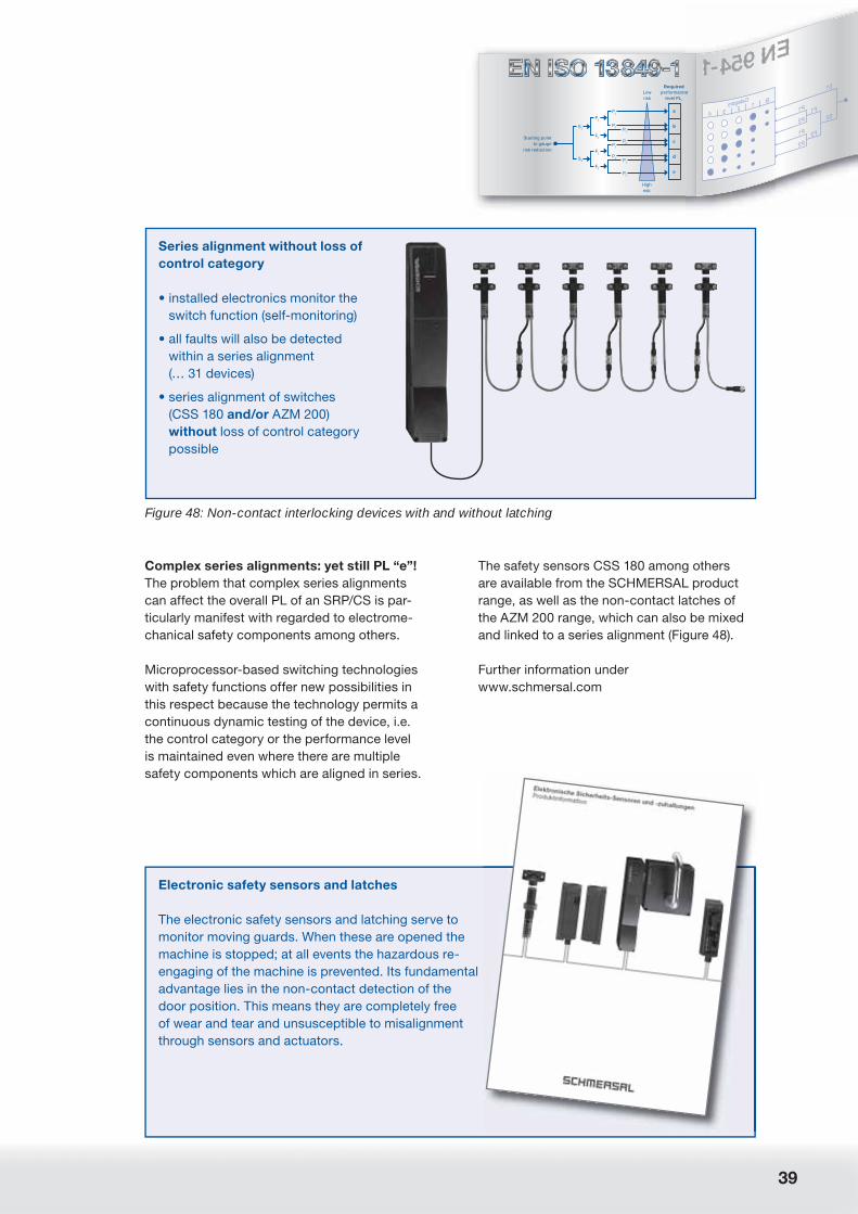
39
Highrisk
Lowrisk
Starting pointto gauge
risk reduction
performance level PLr
Required
S1
S2
F1
F2
F1
F2
P1a
b
c
d
e
P2
P1
P2
P1
P2
P1
P2
Complex series alignments: yet still PL “e”!
The problem that complex series alignments
can affect the overall PL of an SRP/CS is par-
ticularly manifest with regarded to electrome-
chanical safety components among others.
Microprocessor-based switching technologies
with safety functions offer new possibilities in
this respect because the technology permits a
continuous dynamic testing of the device, i.e.
the control category or the performance level
is maintained even where there are multiple
safety components which are aligned in series.
Figure 48: Non-contact interlocking devices with and without latching
Series alignment without loss of
control category
• installed electronics monitor the
switch function (self-monitoring)
• all faults will also be detected
within a series alignment
(… 31 devices)
• series alignment of switches
(CSS 180 and/or AZM 200)
without loss of control category
possible
The safety sensors CSS 180 among others
are available from the SCHMERSAL product
range, as well as the non-contact latches of
the AZM 200 range, which can also be mixed
and linked to a series alignment (Figure 48).
Further information under
www.schmersal.com
Electronic safety sensors and latches
The electronic safety sensors and latching serve to
monitor moving guards. When these are opened the
machine is stopped; at all events the hazardous re-
engaging of the machine is prevented. Its fundamental
advantage lies in the non-contact detection of the
door position. This means they are completely free
of wear and tear and unsusceptible to misalignment
through sensors and actuators.

40
A New Approach to Machine Safety:
EN ISO 13 849-1:2006 – Safety-related Parts of Control Systems
Figure 49: Basic idea behind the SW require-ments in accordance with EN ISO 13 849-1
• For all PL and SRESW + SRASW
• basically measures to avoid faults and
provide defensive programming
• consideration of the fact that faults will
be introduced during the specifi cation
and design of software
• taking the fundamental safety standard
of IEC 61 508-3 as a basis
• … however not to a high scientifi c level
• principally without links to IEC 61 508
• comprehensible, practice oriented and
easy to use
EN ISO 13 849-1:2006 and software
Background
While EN 954-1 is currently not involved with
the subject of “microprocessor-based switch-
ing technology with safety function” (= PES
systems) and thus also not with the matter of
software, this is the case and in all the more
detail with EN ISO 13 849-1:2006. Nevertheless
the requirements have not completely replaced
IEC EN 61 508 (e.g. for applications in PL “e”),
but this is only of interest to developers of PES
systems and will not be discussed further here.
The basic idea behind EN ISO 13 849-1:2006 is
depicted in Figure 49.
Design
The software requirements in prEN the pro-
gramming ISO 13 849-1 are divided into gen-
eral requirements (as cited) as well as require-
ments pertaining to safety-relevant embedded
software and requirements for safety-relevant
application software, whereby there are also
additional divisions according to language
used (LVL¹ or FVL²) and PL’s (refer to Figures 50
and 51).
Limited variability languages (LVL), e.g. KOP, FUB
ISO 13849-1IEC 62061/61511
Safety-relevant application software: SRASW
Language Software range
Full variability languages (FVL), e.g. C/C++, Asm
Safety-relevant embedded software: SRESW
ISO 13849-1IEC 61508-3
ISO 13849-1
IEC 61508-3
Figure 50: “Networking” of safety-oriented software
1) LVL (limited variability language) – programming lan-
guage with limited language range: language type that
provides the capability to implement predefi ned appli-
cation-specifi c and library functions in combination in
order to execute the safety requirement specifi cations.
2) FVL (full variability language) – programming language
with unlimited language range: language type that
provides the capability to implement a wide variety of
functions and applications.

41
Highrisk
Lowrisk
Starting pointto gauge
risk reduction
performance level PLr
Required
S1
S2
F1
F2
F1
F2
P1a
b
c
d
e
P2
P1
P2
P1
P2
P1
P2
General, objective, V model4.6.1
Parametrization4.6.4
SRESW/SRASW in FVL
Basis: PL a, b
4.6.2
Additionally:PL c, d
SRASW in LVL
Basis: PL a, b
4.6.3
Additionally with increasing effectiveness: PL c–e
Special: PL e
Figure 51: The structure of the SW requirements in accordance with paragraph 4.6 of EN ISO 13 849-1:2006
Application
We will not go into details of safety-relevant
embedded software as this only affects EN
ISO 13 849-1:2006 clientele in exceptional
cases. Increasingly what is more typical is,
however, the use of application software in
SRP/CS, whether this is in connection with
safety SPS’s, safety bus systems or safety-ori-
ented drive controls.
EN ISO 13 849-1:2006 recommends taking the
so-called V model as a basis for application
software (and also for embedded software),
as it is already very familiar in the software
branch, if only in a simplifi ed form.
Specification of the safety requirements
ResultVerification
Specificationof the software safety require-
ments
Validatedsoftware
Systemdesign
Integrationtest
Moduledesign
Coding
Moduletest
ValidationValidation
Figure 52: Simplifi ed V model for SRESW and SRASW in EN ISO 13 849-1:2006
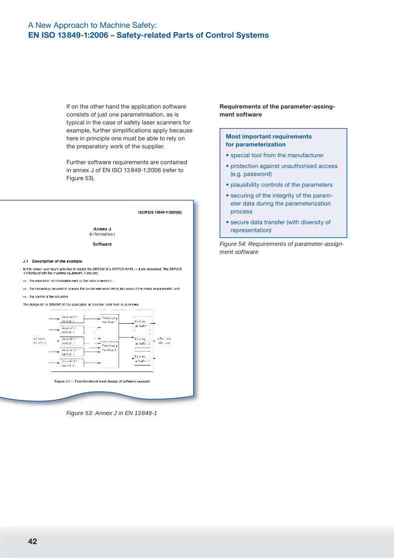
42
A New Approach to Machine Safety:
EN ISO 13 849-1:2006 – Safety-related Parts of Control Systems
Figure 54: Requirements of parameter-assign-ment software
Most important requirements
for parameterization
• special tool from the manufacturer
• protection against unauthorised access
(e.g. password)
• plausibility controls of the parameters
• securing of the integrity of the param-
eter data during the parameterization
process
• secure data transfer (with diversity of
representation)
If on the other hand the application software
consists of just one parametrisation, as is
typical in the case of safety laser scanners for
example, further simplifi cations apply because
here in principle one must be able to rely on
the preparatory work of the supplier.
Further software requirements are contained
in annex J of EN ISO 13 849-1:2006 (refer to
Figure 53).
Requirements of the parameter-assing-
ment software
Figure 53: Annex J in EN 13 849-1

43
Highrisk
Lowrisk
Starting pointto gauge
risk reduction
performance level PLr
Required
S1
S2
F1
F2
F1
F2
P1a
b
c
d
e
P2
P1
P2
P1
P2
P1
P2
EN ISO 13 849-1:2006
vs. IEC EN 62 061
Background
As discussed at the beginning, the IEC EN
62 061 standard is competing against EN
ISO 13 849-1:2006 to be the successor to EN
954-1, even if the term “competing” is slightly
exaggerated in this context. Still, it is no longer
possible to speak of “co-existence” as had
once been envisaged.
In contrast to IEC 61 508 one can furthermore
take it that both IEC EN 62 061 and EN ISO
13 849-1 will also be harmonised under the
EC machinery directive. This means that both
standards will have the advantage of the so-
called supposed impact on their side.
IEC EN 62 061 is the sector specifi c derivate
of IEC EN 61 508 for mechanical engineering.
Apart from this there is, for example, the IEC
EN 61 511¹ standard for the processing indus-
try (for chemical and process engineering).
Originally IEC EN 61 508 was intended ex-
clusively to close a gap, namely the failure of
EN 954-1 to recognise any requirements for
complex SRP/CS, especially with regard to
programmable electronic, i.e. microproces-
sor-based systems with safety functions (PES);
however the IEC 61 508 standards commit-
tee has widened the application range of the
standard in the course of its work to include
discrete electrical and electronic systems
(E/E/PES).
Since as a result of this IEC EN 61 508 has
developed into a fundamental and comprehen-
sive standard for almost all types of safety-re-
lated problems and become correspondingly
complex (with over 350 pages divided into
8 sections), it has generated so-called sec-
tor-specifi c standards for individual branches,
among others in the form of IEC 62 061² for
mechanical engineering.
The typical requirements of the branch are
determined here while requirements that apply
to other branches and design scenarios are
being left out.
ElectricsHydraulicsPneumaticsMechanics
Machineindustry
IEC 62061 IEC 61511
Processingindustry
EN 954(EN ISO 13849)
IEC 61508
Figure 55: Situation with competing standards
1) IEC EN 61 511-1 (VDE 0810-1:2005-05): functional
safety – safety-related systems for the processing
industry – part 1: general, terms, system requirements,
software and hardware
2) IEC EN 62 061-1 (VDE 0113-50): safety of machines
– functional safety of safety-oriented electrical, elec-
tronic and programmable electronic control systems
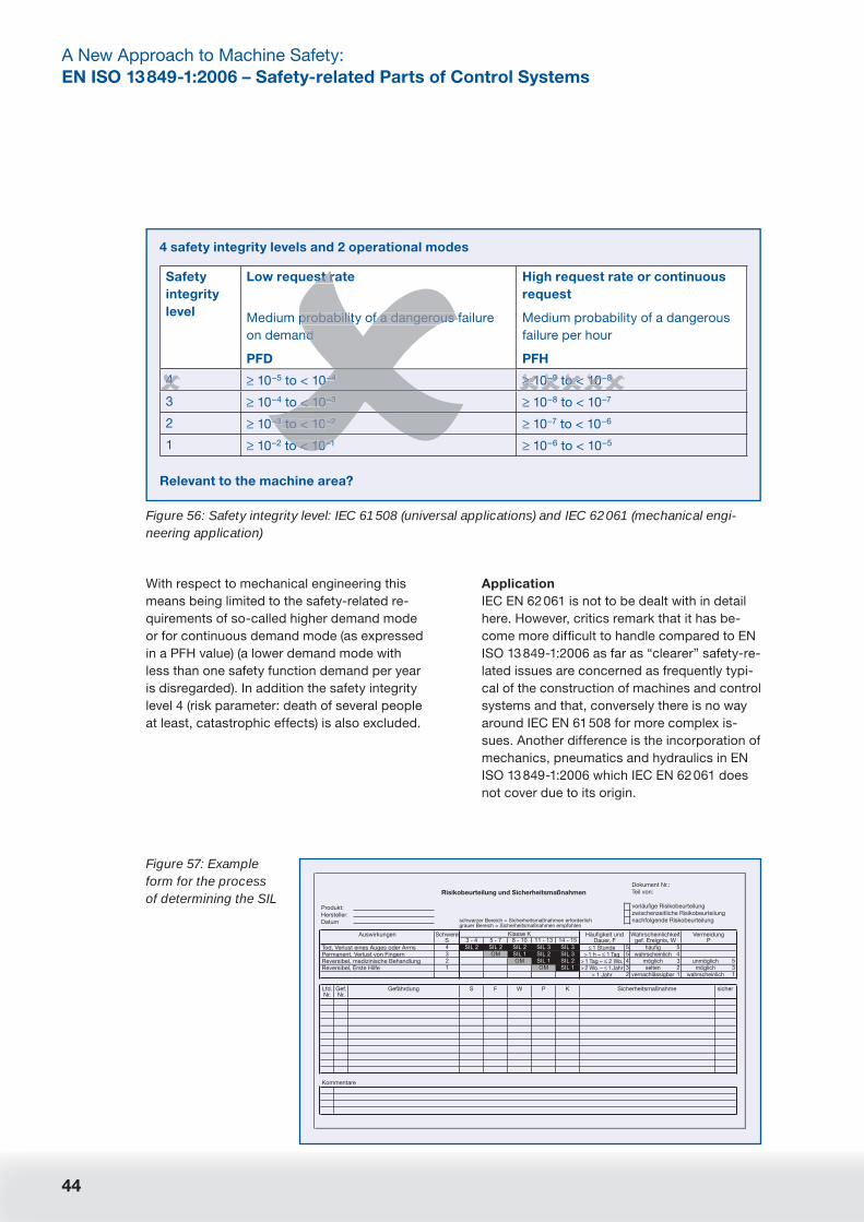
44
A New Approach to Machine Safety:
EN ISO 13 849-1:2006 – Safety-related Parts of Control Systems
With respect to mechanical engineering this
means being limited to the safety-related re-
quirements of so-called higher demand mode
or for continuous demand mode (as expressed
in a PFH value) (a lower demand mode with
less than one safety function demand per year
is disregarded). In addition the safety integrity
level 4 (risk parameter: death of several people
at least, catastrophic effects) is also excluded.
Figure 56: Safety integrity level: IEC 61 508 (universal applications) and IEC 62 061 (mechanical engi-neering application)
4 safety integrity levels and 2 operational modes
Safety
integrity
level
Low request rate
Medium probability of a dangerous failure
on demand
PFD
High request rate or continuous
request
Medium probability of a dangerous
failure per hour
PFH
4 ≥ 10–5 to < 10–4 ≥ 10–9 to < 10–8
3 ≥ 10–4 to < 10–3 ≥ 10–8 to < 10–7
2 ≥ 10–3 to < 10–2 ≥ 10–7 to < 10–6
1 ≥ 10–2 to < 10–1 ≥ 10–6 to < 10–5
Relevant to the machine area?
st r
probability of a dangerous
nd
0–4
< 10–3
–3 to < 10–2
o < 10–1
≥ 10–9 o < 10 84
Application
IEC EN 62 061 is not to be dealt with in detail
here. However, critics remark that it has be-
come more diffi cult to handle compared to EN
ISO 13 849-1:2006 as far as “clearer” safety-re-
lated issues are concerned as frequently typi-
cal of the construction of machines and control
systems and that, conversely there is no way
around IEC EN 61 508 for more complex is-
sues. Another difference is the incorporation of
mechanics, pneumatics and hydraulics in EN
ISO 13 849-1:2006 which IEC EN 62 061 does
not cover due to its origin.
Risikobeurteilung und Sicherheitsmaßnahmen
Produkt:Hersteller:Datum
Tod, Verlust eines Auges oder ArmsPermanent, Verlust von FingernReversibel, medizinische BehandlungReversibel, Erste Hilfe
1 Stunde> 1 h – 1 Tag
> 1 Tag – 2 Wo.> 2 Wo. – 1 Jahr
> 1 Jahr
häufigwahrscheinlich
möglichselten
vernachlässigbar
unmöglichmöglich
wahrscheinlich
Kommentare
Auswirkungen Klasse KSchwereS
Lfd.Nr.
Gef.Nr.
S F W P K sicherGefährdung Sicherheitsmaßnahme
Häufigkeit undDauer, F
Wahrscheinlichkeitgef. Ereignis, W
VermeidungP
Dokument Nr.:Teil von:
vorläufige Risikobeurteilungzwischenzeitliche Risikobeurteilungnachfolgende Riskobeurteilungschwarzer Bereich = Sicherheitsmaßnahmen erforderlich
grauer Bereich = Sicherheitsmaßnahmen empfohlen
Figure 57: Example form for the process of determining the SIL

45
Highrisk
Lowrisk
Starting pointto gauge
risk reduction
performance level PLr
Required
S1
S2
F1
F2
F1
F2
P1a
b
c
d
e
P2
P1
P2
P1
P2
P1
P2
Probability of a dangerous failure per hour
EN ISO 13849-1
PL
PLIEC 62061/IEC 61508
a
Safeguard againstlower risks
Safeguard againsthigher risks
b c d e
1 no special
safetyrequirements
2 3
10–810–5
3 x 10–610–6 10–710–4
Figure 58: Relationship between SIL and PL
Figure 59: Recommended application of IEC 62 061 and ISO 13 849-1 (in revision)
Technology ISO 13 849-1 (in revision) IEC 62 061
A Non-electrics,
e.g. hydraulics
X Disregarded
B Electromechanics,
e.g. relay or simple
Designated architectures1
and up to PL = e
All architectures and up to SIL 3
C Complex electronics,
e.g. programmable
Designated architectures1
and up to PL = d
All architectures and up to SIL 3
D A combined with B Designated architectures1
and up to PL = e
X (EN ISO 13 849-1 for A)
E C combined with B Designated architectures1
and up to PL = d
All architectures and up to SIL 3
F C combined with A, or C
combined with A and B
X2 X3
“X” means that this point is covered by the standard in the column heading.
1) Designated architectures are defi ned in annex B of the EN ISO 13 849-1 (rev.), in order to provide a simplifi ed quantifi -
cation of the performance level.
2) For complex electronics: use of the designated architectures in agreement with EN ISO 13 849-1 (rev.) up to PL = d or
every architecture to IEC 62 061.
3) For non-electrical technology: use of parts in accordance with EN ISO 13 849-1 (rev.) as a partial system.
Planned compatibility of EN ISO 13 849-
1:2006 and IEC EN 62 061 (IEC EN 61 508)
In spite of all this, both standard-setters, i.e.
both the committees of IEC EN 62 061 and EN
ISO 13 849-1:2006 – have made efforts to cre-
ate compatibility between the two standards,
by co-ordinating the safety integrity level and
performance level requirements. Thus SIL 1
corresponds for example to the PL’s “b” or “c”
etc. (refer to Figure 58).
Furthermore both standards provide similar
sounding recommendations concerning which
standard should be applied for which ques-
tions. However there is still room for criticism
as the EN ISO 13 849-1:2006 standard-setter
has departed from this compromise through
the implementation of subsequent alterations,
even if the application table continues to be
included in EN ISO 13 849-1:2006 (refer to
Figure 59).

46
A New Approach to Machine Safety:
EN ISO 13 849-1:2006 – Safety-related Parts of Control Systems
The coming into force
of EN ISO 13 849-1:2006
Current “timetable”
While IEC EN 62 061 has already been formally
passed, EN ISO 13 849:2006 fi nds itself still
at the fi nal ballot stage (FDIS) and it runs the
real risk of a further editorial round. This is why
only a draft standard is available in German
at the present time (as of June 2004), while
62 061 can already be bought in perfect form
as IEC EN 62 061 from Beuth publishers (www.
beuth.de).
However if the current “timetable” remains,
EN ISO 13 849-1 will come into force in 2006
and, after a 3 year transition period, replace
EN 954-1 completely.
When do I have to apply the new EN ISO 13 849-1:2006?Is there any transition period?
Middle of 2006Final draft (FDIS)
Late summer 2006Voting
Herbst 2006Adoption
Transition period November 2009
Harmonizing First quarter of 2007
✔
Figure 60: Up-dated time table (May 2007): According to the latest decisions the now concluded stan-dard has a transition period until November 2009 (which means the new provisions can be already ap-plied from now on, but here is not yet a must to do so), but in November 2009 all confl icting standards (in practical terms ISO 13 849-1:1999 respectively EN 954-1:1996) have to be recalled. Than the “old” standard fi nally will be replaced by EN ISO 13 849-1:2006.
Comparison with the state of the draft
in June 2004
In comparison with the state of the draft in June
2004, EN ISO 13 849-1:2006 demonstrates a
few important amendments in the fi nal version,
among others with respect of the application
range (see above) and the risk graphs. Further-
more one could – albeit with limitations – also
realise PES systems under EN ISO 13 849-1:2006.
With regard to risk graphs, there are now un-
ambiguous specifi cations of which risks lead to
which performance level, i.e. there are no longer
any “double entries” (e.g. optionally PL x or PL y).
What is more, the risk parameter F1 (frequency
and/or duration of the hazardous exposition) is
clarifi ed so that generally “seldom” is taken to
mean > 1 x per hour.
see page 2
(up-dated May 2007)
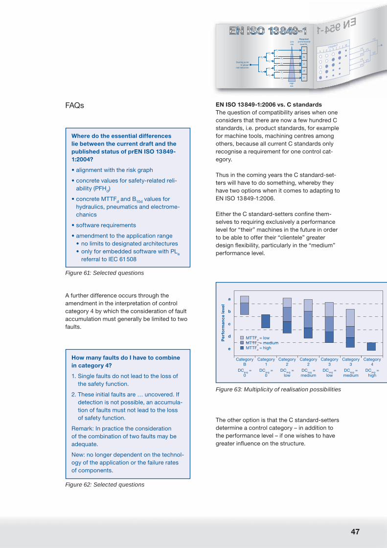
47
Highrisk
Lowrisk
Starting pointto gauge
risk reduction
performance level PLr
Required
S1
S2
F1
F2
F1
F2
P1a
b
c
d
e
P2
P1
P2
P1
P2
P1
P2
Figure 61: Selected questions
Where do the essential differences
lie between the current draft and the
published status of prEN ISO 13 849-
1:2004?
• alignment with the risk graph
• concrete values for safety-related reli-
ability (PFHd)
• concrete MTTFd and B
10d values for
hydraulics, pneumatics and electrome-
chanics
• software requirements
• amendment to the application range
• no limits to designated architectures
• only for embedded software with PLe
referral to IEC 61 508
A further difference occurs through the
amendment in the interpretation of control
category 4 by which the consideration of fault
accumulation must generally be limited to two
faults.
Figure 62: Selected questions
How many faults do I have to combine
in category 4?
1. Single faults do not lead to the loss of
the safety function.
2. These initial faults are … uncovered. If
detection is not possible, an accumula-
tion of faults must not lead to the loss
of safety function.
Remark: In practice the consideration
of the combination of two faults may be
adequate.
New: no longer dependent on the technol-
ogy of the application or the failure rates
of components.
EN ISO 13 849-1:2006 vs. C standards
The question of compatibility arises when one
considers that there are now a few hundred C
standards, i.e. product standards, for example
for machine tools, machining centres among
others, because all current C standards only
recognise a requirement for one control cat-
egory.
Thus in the coming years the C standard-set-
ters will have to do something, whereby they
have two options when it comes to adapting to
EN ISO 13 849-1:2006.
Either the C standard-setters confi ne them-
selves to requiring exclusively a performance
level for “their” machines in the future in order
to be able to offer their “clientele” greater
design fl exibility, particularly in the “medium”
performance level.
Pe
rfo
rma
nc
e le
vel
Category B
DCavg =0
Category 1
DCavg =0
Category 2
DCavg =low
Category 2
DCavg =medium
Category 3
DCavg =low
Category 3
DCavg =medium
Category 4
DCavg =high
a
b
c
d
e
MTTFd = lowMTTFd = mediumMTTFd = high
Figure 63: Multiplicity of realisation possibilities
The other option is that the C standard-setters
determine a control category – in addition to
the performance level – if one wishes to have
greater infl uence on the structure.
FAQs

48
A New Approach to Machine Safety:
EN ISO 13 849-1:2006 – Safety-related Parts of Control Systems
In the meantime we should all be best served
by using the following table (caution when
realising control category 2 with the desig-
nated architecture specifi ed! Refer to the place
already cited).
Figure 64: Selected questions
My C standard demands a category
to control the machine. Will a perfor-
mance level be adequate in the future?
• In principle the declaration of a perfor-
mance level will suffi ce for classifi cation
in the future. However EN ISO 13 849-1
plans the following specifi cation for
each SRP/CS in the user information:
EN ISO 13 849-1:200x
Category X PL Y
Figure 65: Control categories and additional requirements
B 1 2 3 4
Design in accordance with relevant standards,
to withstand expected infl uences
X X X X X
Tried and tested safety principles X X X X
Tried and tested components X
Mean time to dangerous failure – MTTFd
low –
medium
high low –
medium
low –
high
high
Fault detection (tests) X X X
Single fault safety X X
Consideration of fault accumulation X
Diagnostic coverage – DCavg
low –
medium
low –
medium
high
Measures to combat CCF X X X
Principally characterised by Component
selection
Structure

49
Highrisk
Lowrisk
Starting pointto gauge
risk reduction
performance level PLr
Required
S1
S2
F1
F2
F1
F2
P1a
b
c
d
e
P2
P1
P2
P1
P2
P1
P2
Outlook
Without doubt a series of questions remains
with regard to prEN 13 849-1. We will therefore
keep you informed within the framework of the
MRL News of further future clarifi cations as
they emerge.
If one attempts to summarise the effects
of prEN ISO 13849-1, these can be divided
roughly into two groups.
The fi rst is the group of those who must merely
revise the quantifi cation (MTTFd, DC, CCF).
Here we can assume that a machine with SRP/
CSS’s will “pass” the new safety standard if
safety-related factors have been well thought-
out and executed with appropriate quality, and
that no substantial amendments will be neces-
sary as a result.
By contrast, however, amendments may be
required where complex series alignments are
realised (heading: “crash hazard” in the PL
through the summation of residual risks) and
when the designated architecture for category
2 is used.

Notes
50


05/06 V
Elan Schaltelemente GmbH & Co. KG
Im Ostpark 2
D-35435 Wettenberg
Postbox 1109
D-35429 Wettenberg
Tel. +49 (0)641 9848-0
Tel. +49 (0)641 9848-420
E-Mail [email protected]
Internet www.elan.de
K.A. Schmersal GmbH
Industrielle Sicherheitsschaltsysteme
Möddinghofe 30
D-42279 Wuppertal
Postbox 24 02 63
D-42232 Wuppertal
Tel. +49 (0)202 6474-0
Fax +49 (0)202 6474-100
E-Mail [email protected]
Internet www.schmersal.com