Embed Size (px)
Citation preview
Delft University of Technology
A New Approach on the Physical Architecture of CubeSats & PocketQubes
Bouwmeester, Jasper; Gill, Eberhard; Speretta, Stefano; Uludag, Sevket
Publication date2017Document VersionPublisher's PDF, also known as Version of recordPublished inProceedings of the 15th Reinventing Space Conference, 2017, Glasgow
Citation (APA)Bouwmeester, J., Gill, E., Speretta, S., & Uludag, S. (2017). A New Approach on the Physical Architectureof CubeSats & PocketQubes. In Proceedings of the 15th Reinventing Space Conference, 2017, Glasgow[BIS-RS-2017-45] British Interplanetary Society.
Important noteTo cite this publication, please use the final published version (if applicable).Please check the document version above.
CopyrightOther than for strictly personal use, it is not permitted to download, forward or distribute the text or part of it, without the consentof the author(s) and/or copyright holder(s), unless the work is under an open content license such as Creative Commons.
Takedown policyPlease contact us and provide details if you believe this document breaches copyrights.We will remove access to the work immediately and investigate your claim.
This work is downloaded from Delft University of Technology.For technical reasons the number of authors shown on this cover page is limited to a maximum of 10.
Bouwmeester 1 Reinventing Space Conference 2017
Copyright © 2017 by TU Delft. Published by the British Interplanetary Society with permission.
BIS-RS-2017-45
A New Approach on the Physical Architecture of CubeSats & PocketQubes
J. Bouwmeester
Delft University of Technology
Kluyverweg 1, 2629HS Delft, The Netherlands; +31-152784615
E.K.A. Gill
Delft University of Technology
S. Speretta
Delft University of Technology
M.S. Uludağ
Delft University of Technology
ABSTRACT
The dominant architectural approach in CubeSats and PocketQubes is the use of modular physical units, each hosting
(part of the) components of classical (virtual) subsystems. Many of these small satellites, however, also host
subsystems or experiments with slightly alternative approach, e.g. with cellularization of components or the
integration of functions from different virtual subsystems into a single physical unit. These concepts also have been
investigated and proposed by some studies on a much more rigorous implementation. Cellularization of complete
satellite segments, the implementation of artificial stem cells, a satellite which comprises only of outer panels and
plug-and-play technology are examples of these advanced concepts. While they offer promising advantages when
implemented smartly as part of a new architecture, their disadvantages become dominant when such a concept is
implemented in a too rigorous and dogmatic manner. A smartly chosen hybrid of several concepts is investigated. An
advanced outer but flat panel mixes the cellularized concept and integrates many components which interact with the
outside world. Internally, modular systems are still used, but some classical core subsystems can be integrated towards
a single core unit. A lean approach on redundancy and electrical interfaces saves volume (for more payload volume
or smaller satellites) and reduces overall systems complexity. The overall impact on reliability is expected to be
positive when taking development and testing time into account, but this requires more in-depth study to be validated.
KEYWORDS: CubeSat, PocketQube, Architecture, Cellularization, Integration, Miniaturization
1. INTRODUCTION
The physical architecture of a satellite is the foundation
on which all its functions and performance is built upon.
It determines the breakdown of a satellite in physical
subsystems and components, the physical location of
these units and the structural and electrical interfaces
between them.
CubeSats, satellites with a volume of one or more cubic
units of 10 cm, have been introduced in 2001 and grown
in popularity since. This platform was disruptive as it
provided the ability to new players, such as universities
and small companies, to launch their own satellite. At
present, there are hundreds of CubeSats launched per
year. PocketQubes, with a volume of one or more cubic
units of 5 cm, have been introduced since a few years
and. In terms of technology, the use of commercial-off-
the-shelf electronics differentiates how these very small
satellites are developed compared to larger satellites.
These satellites are developed in a modular fashion using
standard interfaces and a physical breakdown along the
traditional breakdown of (virtual) subsystems also used
in larger satellites.
In the chapter 2, a few CubeSats and PocketQubes are
investigated on their physical architecture to provide an
overview of common practices and small experiments.
In chapter 3, an overview and reflection is provided on
advanced architectural concepts. In chapter 4, several of
these concepts are worked out with examples for
practical insight. In chapter 5, a study case is presented
using a subset of advanced ideas to show the impact on
design, complexity and payload volume. Finally,
conclusions and discussion are provided in chapter 6.
Bouwmeester 2 Reinventing Space Conference 2017
2. SURVEY OF CUBESAT AND POCKETQUBE
ARCHITECTURES
In this chapter, examples from literature are provided of
a few CubeSats and PocketQubes. The aim is to identify
the common practices as well as highlighting a few
remarkable aspects related to their physical architecture.
ArduSat-1 and ArduSat-X are open-source single unit
(1U) CubeSats comprising an optical spectrometer and
camera and several other sensors 1, which were the first
satellites launched by the company Spire (formerly
known as NanoSatisfy). The physical architecture uses a
stacked approach with PC/104 compatible units for the
flight computer, electrical power system, a radio
transceiver and an antenna board. The most remarkable
item is a Payload processor module which holds an
ATmega2561 supervisor processor and 16 ATmega328
processor nodes on a single board, all of them Arduino
compatible. Arduino is an open source simplified high
level programming language using a standard set of
microcontrollers and has a wide community support.
This approach allows for distributing experiments to
student teams and is a compromise between modularity
on one hand and volume optimization on the other hand.
The relative payload volume is about half of the satellite
according to figure 2 in the reference paper 1.
BeEagleSat is a 2U CubeSat developed the Istanbul
Technical University in the framework of the QB50
project 2. Its payloads are the QB50 ‘multi needle
Langmuir probe and thermistors’ suite and an X-ray
detector. It comprises several physical subsystems from
different manufacturers for power, attitude control and
high speed radio communication. The main interface is
based on the PC/104 connector. In terms of physical
architecture, the most remarkable is the OBCOMS
which a single board comprising both an onboard
computer and a beacon radio. This is a small step
towards integration of core functionalities on a single
board. The relative payload volume is about one-third of
the satellite, according to figure 1 in the paper 2.
ESTCube-2 is a 3U CubeSat for the demonstration of
Coulomb drag propulsion, a multispectral imager and
advanced communication payloads 3. Noteworthy in the
physical architecture is that the outer structural panels of
the satellite comprise both solar cells as well as the
maximum power point tracking circuitry and a sun
sensor by using aluminum printed circuit boards as
substrate. Also, there is tight integration of core bus
subsystems where several virtual subsystems are sharing
a few onboard microcontrollers. This integrated bus
consumes 0.5U of space.
Galassia is a 2U CubeSat with a Total Electron Count
payload and a quantum entangling demonstration
payload. It has a standard modular physical architecture,
comprising of PC/104 based PCBs for OBC, EPS,
passive attitude control, radio transceiver and the
payloads 4. The relatively simple bus subsystems
consume about 1U, half of the satellite, in total.
The GOMX-4 platform from GomSpace is a standard
satellite platform for 6U CubeSats 5. Its physical
architecture is exemplary for the modular approach in
which many CubeSats are developed. This approach
means that each virtual subsystem typically has one or
more physically distinct units which are connected
through a standard electrical interface (in this case a
PC/104 connector). The most remarkable part of this
architecture is the Software Defined Radio (SDR) which
is used for the Inter Satellite Link (ISL), high speed
transmission to ground and the reception of Automatic
Dependent Surveillance-Broadcast (ADS-B) signals
from airplanes. This shows an integrated platform used
for advanced bus functionality as well as payload
functionality. The fact that a large part of the
functionality resides in software, means that a standard
unit can be (re-)configured and aggregated for different
communication functionalities.
The successful Delfi-C3 6 and Delfi-n3Xt 7 3U CubeSats
from Delft University of Technology (TU Delft) have
been launched in 2008 and 2013 respectively. In terms
of architecture, both follow a modular subsystem
approach similar to GOMX-4. However, both satellites
attempted to provide a single-point-of-failure-free
design. On Delfi-C3, a backup mode was created with
analogue measurements of the thin film solar cell
technology demonstration payload. In lack of time,
priority was given to the nominal mode and the backup
mode was not properly tested and the ground segment
not yet completed. In its almost ten years of operation,
the backup mode was never needed to continue critical
operation but was activated a few times, most likely due
to a false trigger.
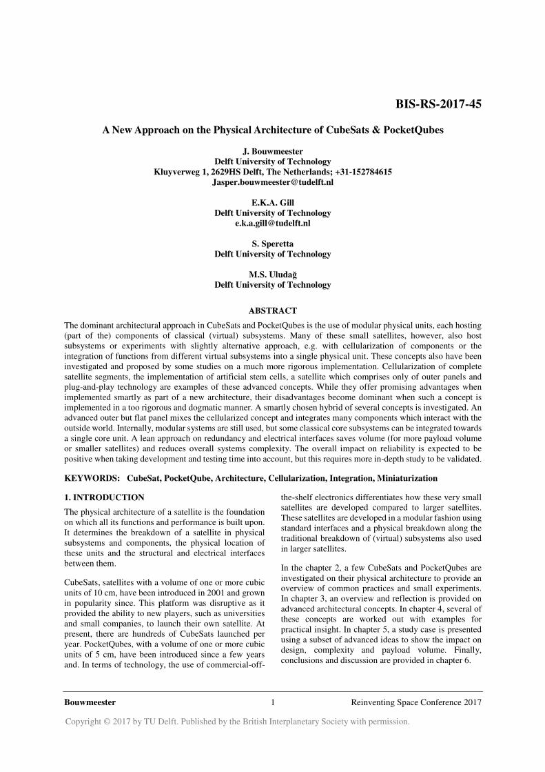
Delfi-n3Xt (shown in Figure 1) used a more classical
redundancy concept, in which critical systems were
duplicated. However, on the data bus interface single-
point-of-failures could not completely be mitigated and
after three months of operations, having completed the
primary mission objective, the satellite became silent
after attempting to switch on a radio transponder. This
transponder was not part of the main mission objectives,
and it was decided to limit the amount of testing to give
priority to the mission critical subsystems and payloads.
The main hypothesis is that an I2C data bus buffer has
shorted the internal communication path.
Bouwmeester 3 Reinventing Space Conference 2017
Figure 1. Delfi-n3Xt Internal Stack
To date, only four PocketQubes have been launched and
only about a dozen are in development, so information
on their architectures is scarce. A website on the 1p
WREN PocketQube 8 reveals that the outer structure,
typically aluminum plated box on CubeSats, has been
completely removed. The small size of the satellite
makes it possible that launch loads are completely
handled by internal rods and/or by Printed Circuit Board
(PCB) used as outer panels. WREN and the UoMBSat1
PocketQube of the University of Malta 9, reveals that
still a modular stack of PCBs is used to host the
subsystems.
Beside the scientific references, a survey of websites,
pictures and hardware displayed on conferences reveals
that a vast majority CubeSats and PocketQubes are
internally built on a modular stack of printed circuit
boards. Typically, each of the functional subsystems is
represented by one or more physical PCBs. While
payload volume differs significantly between the
satellites, a stack of PCBs takes significant volume and
the height of the connector and amount of subsystems
drives total volume consumption of the spacecraft bus.
The dominant architectural approach of mapping
functional (virtual) subsystems (such as the electrical
power subsystem, the command and data handling
subsystems, etcetera) to one or more distinct physical
units which are placed in an internal stack, may be
challenged by some innovative concepts.
3. SURVEY OF INNOVATIVE ARCHITECTURAL
CONCEPTS
Next to literature survey on CubeSat and PocketQube
missions, several papers have been found which address
innovative architectural concepts specifically. A
summary of these papers is provided followed by a
qualitative analysis on its main advantages and
disadvantages.
3.1 Cellular Concept
Cellularized satellites have been proposed to “achieve
cost savings, flexibility and reliability while maintaining
the overall mission performance” by the introduction of
“satlets” 10. A distinction is made between single-
function satlets and system satlets. The single-function
satlets comprises standard modular pieces which can be
combined to meet the mission specific requirements. A
given example is the use of spatially distributed reaction
wheel assemblies, which together provide the total
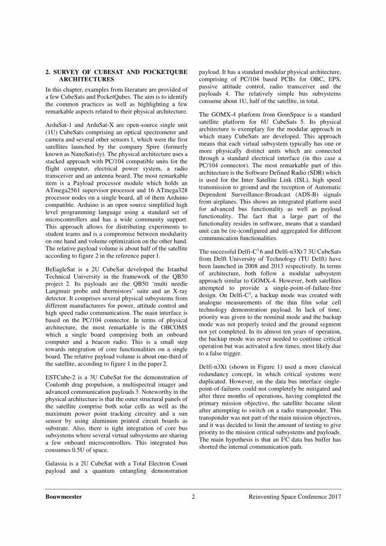
torque and momentum storage. System satlets can be
regarded as a module which integrates several subsystem
functions such that it can operate as an independent
system. An example of a physical breakdown is shown
in Figure 2, which comprises a modular connectable
nanosatellite-scale package which integrates core
satellite functions such as electrical power acquisition
and storage, attitude determination and control and
computational processing.
Figure 2. Example physical breakdown of a
cellularized satellite using ‘system satlets’
The resources can be shared with the rest of the satellite
in a building-block fashion. The benefits mentioned are
thought to be acquired with the aid of mass production
and integration in many satellites of these standard
building blocks. A demonstration of this concept is
planned for launch by the end of 2017 on the eXCITe
mission which comprises 14 of the HISat blocks together
with several payloads, deployable solar array and high
data rate communication radios.
satellite
system satlets
satlet 1
electrical power
solar cells
batteries
electronics
attitude control
sensors
actuators
electronics
shell
structural
body
structural interfaces
electrical
interfaces
onboard computer
satlet 2
electrical power
solar cells
batteries
electronics
attitude control
sensors
actuators
electronics
shell
structural
body
structural interfaces
electrical
interfaces
onboard computer
satlet X
other systems
Bouwmeester 4 Reinventing Space Conference 2017
The satlet concept is relatively simple to comprehend
and implement. Its advantages are the ability to scale up
the technical capacity of the satellite with mission
demands and increase potential reliability by introducing
graceful degradation opportunities. It disadvantage is
that one loses system efficiencies and optimizations
which come with larger systems or components. The
single-function cellular concept will be investigated
further in next chapter. The system level satlets
combines integration of several satellite core
functionalities subsystems with cellularization. An
additional disadvantage here is that this concept is
severely restricts physical configuration options and
fixes the ratio of the technical specifications. For
example, if a mission requires the equivalent
computational power of ten satlets, the satellite would
also receive ten times the satlet data storage, ten similar
attitude sensors and actuators, ten times the solar cells,
while it is not sure if this is truly needed. Also one can
question the added benefit of a satlet with solar cells, if
one still adds a non cellular deployable solar array like
in the eXCITe mission example. However, aspects of the
system satles concept may still be attractive to
investigate, such as the integration of satellite core
functions into a single physical unit. CubeSats and
PocketQubes always have six sides of the body. This
fact can be used to investigate system satlets which
integrates components and satellite functions which are
typically residing on each side, such as sun sensors. But
also potentially omnidirectional radio communication
could be attractive to investigate. Finally, an attractive
option could be to use PocketQube sized components
and systems as cells for CubeSats.
In another recent study 11 it was found that a physical
architecture based on an OBC with a single-master data
communication bus exhibits a relative high amount of
failures (~40% were never head) , followed by an OBC
connecting to separate buses to subsystems. The best
statistics were provided by CubeSats based on a
distributed design using a multi-master bus, for which
80% of the CubeSats fulfilled (part of) its objectives and
all were heard of. The same study also investigates
correlation between mission success and the amount of
redudant subsystems (up to three) which are regarded as
critical (OBC, EPS, COMMS). Only a weak correlation
is found, since with two redundant subsystems the
reliability seems to increase w.r.t. a singular system, but
a slight decrease is seen with three w.r.t. two redundant
subsystems. This correlation is used as on of key
arguments to propose a cellular architectural concept
which is different from the other satlet concept. In this
study, the use of Artificial Stem Cells (ASCs) is
proposed based on the anology of biological cells 11.The
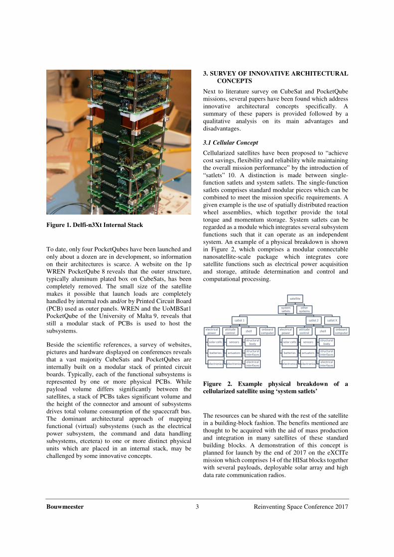
ASC comprises non-volatile memory (DNA), a central
microcontroller (macromollecular machinery) and
several microcontrollers with generic input and outputs
(proteins) to perform tasks and connect to the outside
world.
Figure 3. Sketch of a four protein ASC configuration
The practical application is demonstrated on SME-SAT
by a four protein cell (see Figure 3), each of the proteins
used to drive a identical Control Moment Gyro (CMG)
and a different small technology demonstration payload.
This is just a very simple demonstration, since the
intended architecture would consists of multiple cells,
with proteins of different cells being cross-strapped with
devices (such as gyros) using multiple different
communication busses.
The concept and technology demonstration described in
the paper 11 advocates and clearly explains the use of
cellularization for graceful degeneration. However, the
paper also states that reconfiguration of the ASC
function, the communication paths and potential cross-
strapping payloads between the ASCs has been
considered but not implemented as it “was deemed
unnessessarily complicated” for the SME-SAT mission.
The paper fails to describe how higher level satellite
functions could be implemented as ASCs in a reliable
and practical manner, which gives rise to the question if
the biological anology can really be followed. The
complexity of DNA and cells in biology is tremendous
and not yet fully understood. Also, in biology there is a
physical mobility of cells which is very difficult to
mimic with its technical counterpart. The benefits of
mixing attitude control actuators and payloads to a
single ASC in the example seems arbitrary and is not
explained. The paper continuous with a benchtop
demonstration of a complete ASC based attitude control
subsystem. The complexity of the design prohibits a full
sumary of the design, but the main conclusions from the
paper are that a reliability increase of the system can be
Bouwmeester 5 Reinventing Space Conference 2017
expected mainly due to potential reconfiguration of the
software tasks of proteins and the graceful degeneration
features of the concept. It however comes at the expense
of significanlty higher power consumption (+77%) and
higher complexity compared to a traditional design.
While the concept of ASCs is theoretically interesting, it
is too far fetched to implement in the near to mid-term
future and it is not yet clear if the benefits on the long
term will outweigh its costs.
3.2 Panel Concept
A ‘nano-modular format’ (NMF) has been proposed for
CubeSats which focusses on a different structural
integration concept 12. The six faces of a CubeSat form
the basis which comprises a structural outer panel with
hinges towards the other faces and holds part of all
internal equipment which can be placed in a pyramid-
shaped envelope. A 1U CubeSat thus always consists of
six physical distinct units, while for the larger CubeSats
the configuration it can be extended by using 1U units
placed side-by-side or using a larger base panel. The
hinges and electrical connections between the panels are
supposed to quickly integrate panels towards a complete
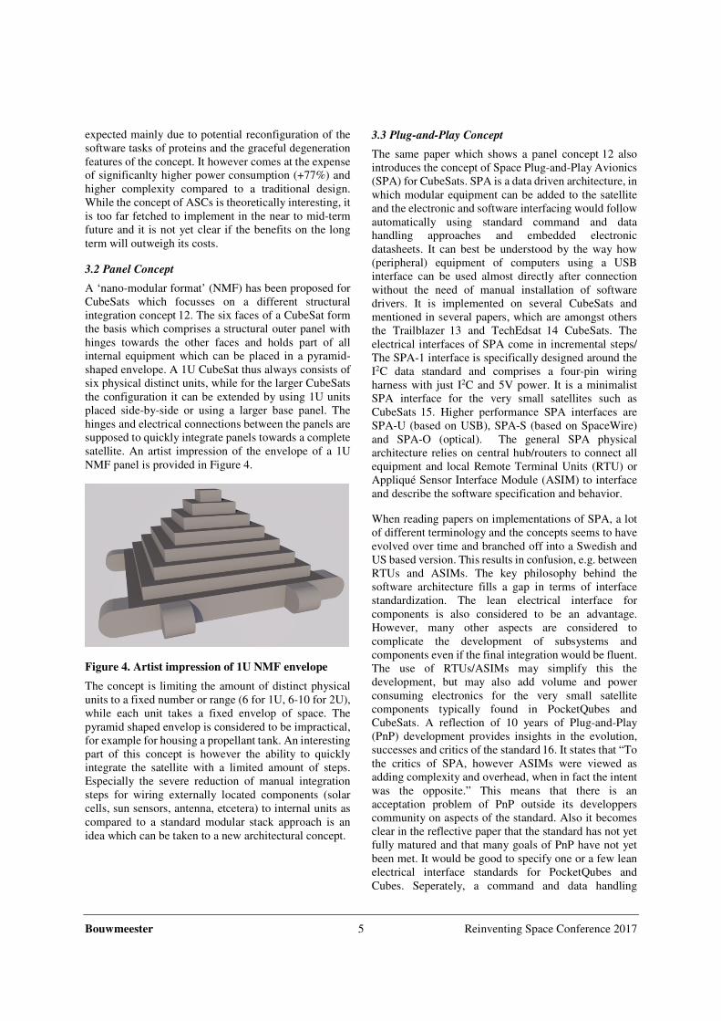
satellite. An artist impression of the envelope of a 1U
NMF panel is provided in Figure 4.
Figure 4. Artist impression of 1U NMF envelope
The concept is limiting the amount of distinct physical
units to a fixed number or range (6 for 1U, 6-10 for 2U),
while each unit takes a fixed envelop of space. The
pyramid shaped envelop is considered to be impractical,
for example for housing a propellant tank. An interesting
part of this concept is however the ability to quickly
integrate the satellite with a limited amount of steps.
Especially the severe reduction of manual integration
steps for wiring externally located components (solar
cells, sun sensors, antenna, etcetera) to internal units as
compared to a standard modular stack approach is an
idea which can be taken to a new architectural concept.
3.3 Plug-and-Play Concept
The same paper which shows a panel concept 12 also
introduces the concept of Space Plug-and-Play Avionics
(SPA) for CubeSats. SPA is a data driven architecture, in
which modular equipment can be added to the satellite
and the electronic and software interfacing would follow
automatically using standard command and data
handling approaches and embedded electronic
datasheets. It can best be understood by the way how
(peripheral) equipment of computers using a USB
interface can be used almost directly after connection
without the need of manual installation of software
drivers. It is implemented on several CubeSats and
mentioned in several papers, which are amongst others
the Trailblazer 13 and TechEdsat 14 CubeSats. The
electrical interfaces of SPA come in incremental steps/
The SPA-1 interface is specifically designed around the
I2C data standard and comprises a four-pin wiring
harness with just I2C and 5V power. It is a minimalist
SPA interface for the very small satellites such as
CubeSats 15. Higher performance SPA interfaces are
SPA-U (based on USB), SPA-S (based on SpaceWire)
and SPA-O (optical). The general SPA physical
architecture relies on central hub/routers to connect all
equipment and local Remote Terminal Units (RTU) or
Appliqué Sensor Interface Module (ASIM) to interface
and describe the software specification and behavior.
When reading papers on implementations of SPA, a lot
of different terminology and the concepts seems to have
evolved over time and branched off into a Swedish and
US based version. This results in confusion, e.g. between
RTUs and ASIMs. The key philosophy behind the
software architecture fills a gap in terms of interface
standardization. The lean electrical interface for
components is also considered to be an advantage.
However, many other aspects are considered to
complicate the development of subsystems and
components even if the final integration would be fluent.
The use of RTUs/ASIMs may simplify this the
development, but may also add volume and power
consuming electronics for the very small satellite
components typically found in PocketQubes and
CubeSats. A reflection of 10 years of Plug-and-Play
(PnP) development provides insights in the evolution,
successes and critics of the standard 16. It states that “To
the critics of SPA, however ASIMs were viewed as
adding complexity and overhead, when in fact the intent
was the opposite.” This means that there is an
acceptation problem of PnP outside its developpers
community on aspects of the standard. Also it becomes
clear in the reflective paper that the standard has not yet
fully matured and that many goals of PnP have not yet
been met. It would be good to specify one or a few lean
electrical interface standards for PocketQubes and
Cubes. Seperately, a command and data handling
Bouwmeester 6 Reinventing Space Conference 2017
standard can be developped in line with the PnP
philosophy, in which the housekeeping data, the
commanding and the specification of components is
completely and uniformely described in a hardware
abstraction and service layer code, such that it can be
handled by application layer software in an autonomous
and transparant manner. The parallel development of an
public electrical interface standard and a open source
software PnP standard will facilitate maturation of the
standards on their own pace and provides a higher
chance for acceptation than a single combined solution
which requires a too disruptive transition and a vendor
lockin.
3.4 Lean Electrical Interfaces
Electrical interfaces are a dominant aspect of
modularization and can have a significant impact in the
available volume. The connectors used consume an
amount of Printed Circuit Board (PCB) area and define
the minimum distance between PCBs. In a very recent
study (currently under review for journal publication), it
has been found that a very versatile standard in not only
consuming a lot of volume due to the connector size, but
it also leads to (potential) incompatibility between
physical subsystems of different vendors. For this
reason, a very lean electrical interface standard for
PocketQubes and CubeSats has been investigated and
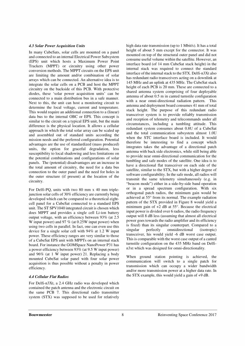
proposed. These are respectively a 9-pin and 14-pin
electrical interface using a 2 mm pitched stackable
connector. The pin definition is shown in Figure 5. The
chosen data bus is RS-485, which is a linear differential
bus (low noise sensitivity) running at 500 kbit/s and 1
Mbit/s respectively. The four and respectively eight
power distribution lines are providing a switchable
protected unregulated voltage to minimize the amount of
conversion steps and associated power losses.
Figure 5. Proposed PQ9 and CS14 electrical interface
standards.
One step further from a lean electrical interface, would
be devices which are self-powered and have a wireless
interface. They don’t have wiring harness, which saves
volume and potentially also reduces integration
complexity.
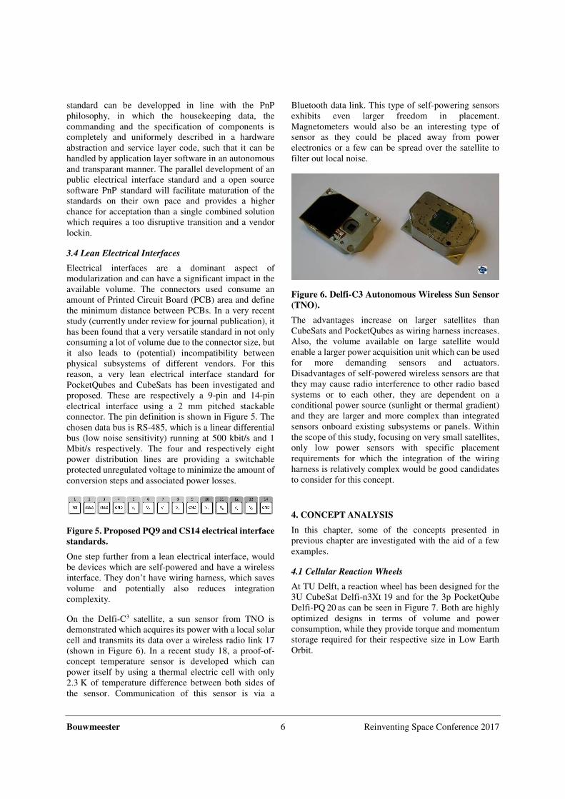
On the Delfi-C3 satellite, a sun sensor from TNO is
demonstrated which acquires its power with a local solar
cell and transmits its data over a wireless radio link 17
(shown in Figure 6). In a recent study 18, a proof-of-
concept temperature sensor is developed which can
power itself by using a thermal electric cell with only
2.3 K of temperature difference between both sides of
the sensor. Communication of this sensor is via a
Bluetooth data link. This type of self-powering sensors
exhibits even larger freedom in placement.
Magnetometers would also be an interesting type of
sensor as they could be placed away from power
electronics or a few can be spread over the satellite to
filter out local noise.
Figure 6. Delfi-C3 Autonomous Wireless Sun Sensor
(TNO).
The advantages increase on larger satellites than
CubeSats and PocketQubes as wiring harness increases.
Also, the volume available on large satellite would
enable a larger power acquisition unit which can be used
for more demanding sensors and actuators.
Disadvantages of self-powered wireless sensors are that
they may cause radio interference to other radio based
systems or to each other, they are dependent on a
conditional power source (sunlight or thermal gradient)
and they are larger and more complex than integrated
sensors onboard existing subsystems or panels. Within
the scope of this study, focusing on very small satellites,
only low power sensors with specific placement
requirements for which the integration of the wiring
harness is relatively complex would be good candidates
to consider for this concept.
4. CONCEPT ANALYSIS
In this chapter, some of the concepts presented in
previous chapter are investigated with the aid of a few
examples.
4.1 Cellular Reaction Wheels
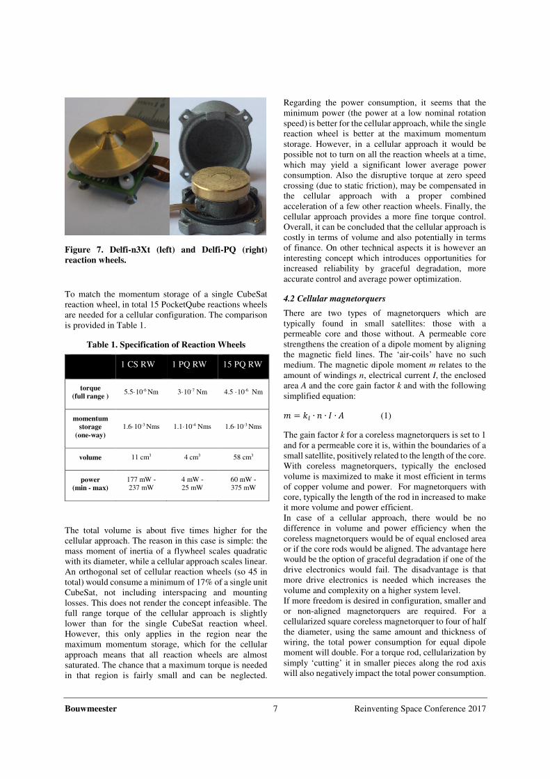
At TU Delft, a reaction wheel has been designed for the
3U CubeSat Delfi-n3Xt 19 and for the 3p PocketQube
Delfi-PQ 20 as can be seen in Figure 7. Both are highly
optimized designs in terms of volume and power
consumption, while they provide torque and momentum
storage required for their respective size in Low Earth
Orbit.
Bouwmeester 7 Reinventing Space Conference 2017
Figure 7. Delfi-n3Xt (left) and Delfi-PQ (right)
reaction wheels.
To match the momentum storage of a single CubeSat
reaction wheel, in total 15 PocketQube reactions wheels
are needed for a cellular configuration. The comparison
is provided in Table 1.
Table 1. Specification of Reaction Wheels
1 CS RW 1 PQ RW 15 PQ RW
torque
(full range ) 5.5·10-6 Nm 3·10-7 Nm 4.5 ·10-6 Nm
momentum
storage
(one-way)
1.6·10-3 Nms 1.1·10-4 Nms 1.6·10-3 Nms
volume 11 cm3 4 cm3 58 cm3
power
(min - max)
177 mW -
237 mW
4 mW -
25 mW
60 mW -
375 mW
The total volume is about five times higher for the
cellular approach. The reason in this case is simple: the
mass moment of inertia of a flywheel scales quadratic
with its diameter, while a cellular approach scales linear.
An orthogonal set of cellular reaction wheels (so 45 in
total) would consume a minimum of 17% of a single unit
CubeSat, not including interspacing and mounting
losses. This does not render the concept infeasible. The
full range torque of the cellular approach is slightly
lower than for the single CubeSat reaction wheel.
However, this only applies in the region near the
maximum momentum storage, which for the cellular
approach means that all reaction wheels are almost
saturated. The chance that a maximum torque is needed
in that region is fairly small and can be neglected.
Regarding the power consumption, it seems that the
minimum power (the power at a low nominal rotation
speed) is better for the cellular approach, while the single
reaction wheel is better at the maximum momentum
storage. However, in a cellular approach it would be
possible not to turn on all the reaction wheels at a time,
which may yield a significant lower average power
consumption. Also the disruptive torque at zero speed
crossing (due to static friction), may be compensated in
the cellular approach with a proper combined
acceleration of a few other reaction wheels. Finally, the
cellular approach provides a more fine torque control.
Overall, it can be concluded that the cellular approach is
costly in terms of volume and also potentially in terms
of finance. On other technical aspects it is however an
interesting concept which introduces opportunities for
increased reliability by graceful degradation, more
accurate control and average power optimization.
4.2 Cellular magnetorquers
There are two types of magnetorquers which are
typically found in small satellites: those with a
permeable core and those without. A permeable core
strengthens the creation of a dipole moment by aligning
the magnetic field lines. The ‘air-coils’ have no such
medium. The magnetic dipole moment m relates to the
amount of windings n, electrical current I, the enclosed
area A and the core gain factor k and with the following
simplified equation:
� = �� ∙ � ∙ � ∙ � (1)
The gain factor k for a coreless magnetorquers is set to 1
and for a permeable core it is, within the boundaries of a
small satellite, positively related to the length of the core.
With coreless magnetorquers, typically the enclosed
volume is maximized to make it most efficient in terms
of copper volume and power. For magnetorquers with
core, typically the length of the rod in increased to make
it more volume and power efficient.
In case of a cellular approach, there would be no
difference in volume and power efficiency when the
coreless magnetorquers would be of equal enclosed area
or if the core rods would be aligned. The advantage here
would be the option of graceful degradation if one of the
drive electronics would fail. The disadvantage is that
more drive electronics is needed which increases the
volume and complexity on a higher system level.
If more freedom is desired in configuration, smaller and
or non-aligned magnetorquers are required. For a
cellularized square coreless magnetorquer to four of half
the diameter, using the same amount and thickness of
wiring, the total power consumption for equal dipole
moment will double. For a torque rod, cellularization by
simply ‘cutting’ it in smaller pieces along the rod axis
will also negatively impact the total power consumption.
Bouwmeester 8 Reinventing Space Conference 2017
4.3 Solar Power Acquisition Units
In many CubeSats, solar cells are mounted on a panel
and connected to an internal Electrical Power Subsystem
(EPS) unit which hosts a Maximum Power Point
Trackers (MPPT) or circuitry using other power
conversion methods. The MPPT circuits on the EPS unit
are limiting the amount and/or combination of solar
arrays which can be connected. An alternative idea is to
integrate the solar cells on a PCB and host the MPPT
circuitry on the backside of this PCB. With protective
diodes, these ‘solar power acquisition units’ can be
connected to a main distribution bus in a safe manner.
Next to this, the unit can host a monitoring circuit to
determine the local voltage, current and temperature.
This would require an additional connection to a (linear)
data bus to the internal OBC or EPS. This concept is
similar to the circuit on a typical EPS unit, but the main
difference is the physical location. It allows a cellular
approach in which the total solar array can be scaled up
and assembled out of standard units according the
mission needs and the preferred configuration. Potential
advantages are the use of standardized (mass produced)
units, the option for graceful degradation, less
susceptibility to local shadowing and less limitations on
the potential combinations and configurations of solar
panels. The (potential) disadvantages are an increase in
the total amount of circuitry, the need for a data bus
connection to the outer panel and the need for holes in
the outer structure (if present) at the location of the
circuitry.
For Delfi-PQ, units with two 80 mm x 40 mm triple-
junction solar cells of 30% efficiency are currently being
developed which can be compared to a theoretical eight-
cell panel for a CubeSat connected to a standard EPS
unit. The ST SPV1040 integrated circuit is chosen which
does MPPT and provides a single cell Li-ion battery
output voltage, with an efficiency between 93% (at 2.5
W input power) and 97 % (at 0.25W input power) when
using two cells in parallel. In fact, one can even use this
device for a single solar cell with 94% at 1.2 W input
power. These efficiency ranges are very similar to those
of a CubeSat EPS unit with MPPTs on an internal stack
board. For instance the GOMSpace NanoPower P31 has
a power efficiency between 93% (at 9.5 W input power)
and 96% (at 1 W input power) 21. Replacing a body
mounted CubeSat solar panel with four solar power
acquisition is thus possible without a penalty in power
efficiency.
4.4 Cellular Flat Radios
For Delfi-n3Xt, a 2.4 GHz radio was developed which
contained the patch antenna and the electronic circuit on
the same PCB 7. This directional radio transmitter
system (STX) was supposed to be used for relatively
high data rate transmission (up to 1 Mbit/s). It has a total
height of about 5 mm except for the connector. It was
mounted on top of the structural outer panel and did not
consume useful volume within the satellite. However, an
interface board (of 14 mm CubeSat stack height) in the
internal stack was required to connect the standard
interface of the internal stack to the STX. Delfi-n3Xt also
has redundant radio transceivers acting on a downlink at
145 MHz and an uplink at 435 MHz. The CubeSat stack
height of each PCB is 20 mm. These are connected to a
shared antenna system comprising of four deployable
antenna of about 0.5 m in canted turnstile configuration
with a near omni-directional radiation pattern. This
antenna and deployment board consumes 41 mm of total
stack height. The purpose of this redundant radio
transceiver system is to provide reliably transmission
and reception of telemetry and telecommands under all
circumstances, including a tumbling attitude. This
redundant system consumes about 0.8U of a CubeSat
and the total communication subsystem almost 1.0U
when the STC interface board is included. It would
therefore be interesting to find a concept which
integrates takes the advantage of a directional patch
antenna with back side electronics, while still being able
to provide near omni-directional communication for the
tumbling and safe modes of the satellite. One idea is to
have a directional flat transceiver on each side of the
satellite, similar to the STX, but with a higher degree of
software configurability. In the safe mode, all radios will
transmit the same telemetry simultaneously (e.g. in
“beacon mode”) either in a side-by-side band operation
or in a spread spectrum configuration. With six
orthogonal patch radios, the minimum gain would be
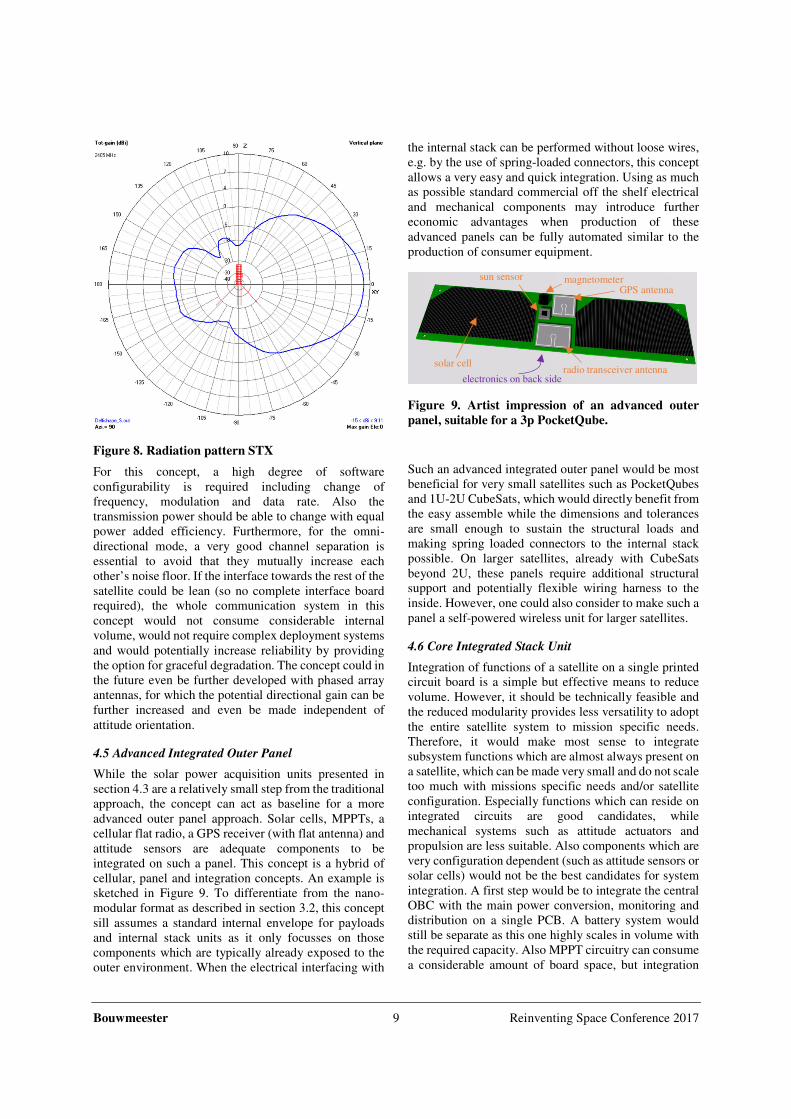
achieved at 55° from its normal. The example radiation
pattern of the STX provided in Figure 8 would yield a
minimum gain of +2 dB at 55°. Because the electrical
input power is divided over 6 radios, the radio frequency
output will 8 dB less (assuming that almost all electrical
power goes towards the radio amplifier and its efficiency
is fixed) than its singular counterpart. Compared to a
singular perfectly omnidirectional (isotropic)
transceiver, his would yield -6 dB worst case output.
This is comparable with the worst case output of a canted
turnstile configuration on the 435 MHz band on Delfi-
n3xt which was designed for omni-directionality.
When ground station pointing is achieved, the
communication will switch to a single patch for
transmission which can occupy a wider bandwidth
and/or more transmission power at a higher data rate. In
the STX example, this would yield a gain of +9 dB.
Bouwmeester 9 Reinventing Space Conference 2017
Figure 8. Radiation pattern STX
For this concept, a high degree of software
configurability is required including change of
frequency, modulation and data rate. Also the
transmission power should be able to change with equal
power added efficiency. Furthermore, for the omni-
directional mode, a very good channel separation is
essential to avoid that they mutually increase each
other’s noise floor. If the interface towards the rest of the
satellite could be lean (so no complete interface board
required), the whole communication system in this
concept would not consume considerable internal
volume, would not require complex deployment systems
and would potentially increase reliability by providing
the option for graceful degradation. The concept could in
the future even be further developed with phased array
antennas, for which the potential directional gain can be
further increased and even be made independent of
attitude orientation.
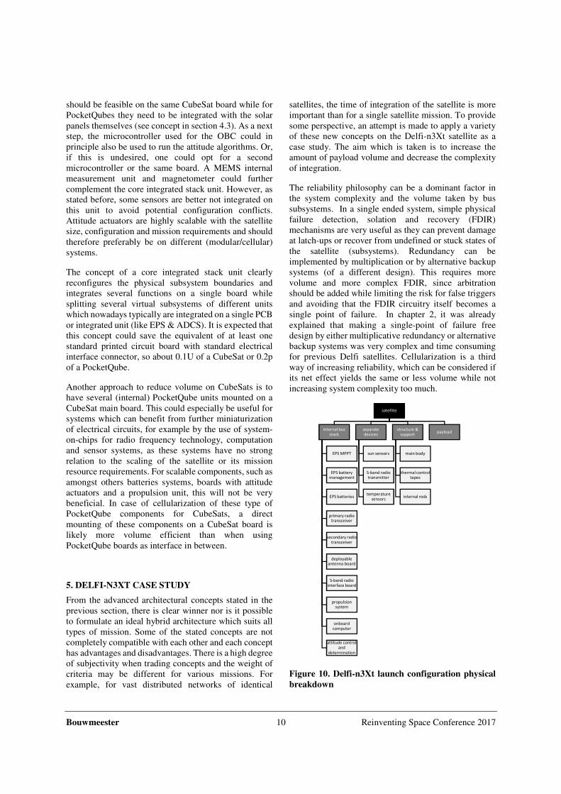
4.5 Advanced Integrated Outer Panel
While the solar power acquisition units presented in
section 4.3 are a relatively small step from the traditional
approach, the concept can act as baseline for a more
advanced outer panel approach. Solar cells, MPPTs, a
cellular flat radio, a GPS receiver (with flat antenna) and
attitude sensors are adequate components to be
integrated on such a panel. This concept is a hybrid of
cellular, panel and integration concepts. An example is
sketched in Figure 9. To differentiate from the nano-
modular format as described in section 3.2, this concept
sill assumes a standard internal envelope for payloads
and internal stack units as it only focusses on those
components which are typically already exposed to the
outer environment. When the electrical interfacing with
the internal stack can be performed without loose wires,
e.g. by the use of spring-loaded connectors, this concept
allows a very easy and quick integration. Using as much
as possible standard commercial off the shelf electrical
and mechanical components may introduce further
economic advantages when production of these
advanced panels can be fully automated similar to the
production of consumer equipment.
Figure 9. Artist impression of an advanced outer
panel, suitable for a 3p PocketQube.
Such an advanced integrated outer panel would be most
beneficial for very small satellites such as PocketQubes
and 1U-2U CubeSats, which would directly benefit from
the easy assemble while the dimensions and tolerances
are small enough to sustain the structural loads and
making spring loaded connectors to the internal stack
possible. On larger satellites, already with CubeSats
beyond 2U, these panels require additional structural
support and potentially flexible wiring harness to the
inside. However, one could also consider to make such a
panel a self-powered wireless unit for larger satellites.
4.6 Core Integrated Stack Unit
Integration of functions of a satellite on a single printed
circuit board is a simple but effective means to reduce
volume. However, it should be technically feasible and
the reduced modularity provides less versatility to adopt
the entire satellite system to mission specific needs.
Therefore, it would make most sense to integrate
subsystem functions which are almost always present on
a satellite, which can be made very small and do not scale
too much with missions specific needs and/or satellite
configuration. Especially functions which can reside on
integrated circuits are good candidates, while
mechanical systems such as attitude actuators and
propulsion are less suitable. Also components which are
very configuration dependent (such as attitude sensors or
solar cells) would not be the best candidates for system
integration. A first step would be to integrate the central
OBC with the main power conversion, monitoring and
distribution on a single PCB. A battery system would
still be separate as this one highly scales in volume with
the required capacity. Also MPPT circuitry can consume
a considerable amount of board space, but integration
solar cell
GPS antenna
radio transceiver antenna electronics on back side
sun sensor magnetometer
Bouwmeester 10 Reinventing Space Conference 2017
should be feasible on the same CubeSat board while for
PocketQubes they need to be integrated with the solar
panels themselves (see concept in section 4.3). As a next
step, the microcontroller used for the OBC could in
principle also be used to run the attitude algorithms. Or,
if this is undesired, one could opt for a second
microcontroller or the same board. A MEMS internal
measurement unit and magnetometer could further
complement the core integrated stack unit. However, as
stated before, some sensors are better not integrated on
this unit to avoid potential configuration conflicts.
Attitude actuators are highly scalable with the satellite
size, configuration and mission requirements and should
therefore preferably be on different (modular/cellular)
systems.
The concept of a core integrated stack unit clearly
reconfigures the physical subsystem boundaries and
integrates several functions on a single board while
splitting several virtual subsystems of different units
which nowadays typically are integrated on a single PCB
or integrated unit (like EPS & ADCS). It is expected that
this concept could save the equivalent of at least one
standard printed circuit board with standard electrical
interface connector, so about 0.1U of a CubeSat or 0.2p
of a PocketQube.
Another approach to reduce volume on CubeSats is to
have several (internal) PocketQube units mounted on a
CubeSat main board. This could especially be useful for
systems which can benefit from further miniaturization
of electrical circuits, for example by the use of system-
on-chips for radio frequency technology, computation
and sensor systems, as these systems have no strong
relation to the scaling of the satellite or its mission
resource requirements. For scalable components, such as
amongst others batteries systems, boards with attitude
actuators and a propulsion unit, this will not be very
beneficial. In case of cellularization of these type of
PocketQube components for CubeSats, a direct
mounting of these components on a CubeSat board is
likely more volume efficient than when using
PocketQube boards as interface in between.
5. DELFI-N3XT CASE STUDY
From the advanced architectural concepts stated in the
previous section, there is clear winner nor is it possible
to formulate an ideal hybrid architecture which suits all
types of mission. Some of the stated concepts are not
completely compatible with each other and each concept
has advantages and disadvantages. There is a high degree
of subjectivity when trading concepts and the weight of
criteria may be different for various missions. For
example, for vast distributed networks of identical
satellites, the time of integration of the satellite is more
important than for a single satellite mission. To provide
some perspective, an attempt is made to apply a variety
of these new concepts on the Delfi-n3Xt satellite as a
case study. The aim which is taken is to increase the
amount of payload volume and decrease the complexity
of integration.
The reliability philosophy can be a dominant factor in
the system complexity and the volume taken by bus
subsystems. In a single ended system, simple physical
failure detection, solation and recovery (FDIR)
mechanisms are very useful as they can prevent damage
at latch-ups or recover from undefined or stuck states of
the satellite (subsystems). Redundancy can be
implemented by multiplication or by alternative backup
systems (of a different design). This requires more
volume and more complex FDIR, since arbitration
should be added while limiting the risk for false triggers
and avoiding that the FDIR circuitry itself becomes a
single point of failure. In chapter 2, it was already
explained that making a single-point of failure free
design by either multiplicative redundancy or alternative
backup systems was very complex and time consuming
for previous Delfi satellites. Cellularization is a third
way of increasing reliability, which can be considered if
its net effect yields the same or less volume while not
increasing system complexity too much.
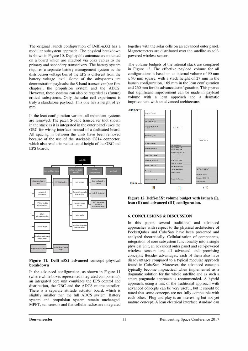
Figure 10. Delfi-n3Xt launch configuration physical
breakdown
satellite
internal bus stack
EPS MPPT
EPS battery management
EPS batteries
primary radio transceiver
secondary radio transceiver
deployable antenna board
S-band radio interface board
propulsion system
onboard
computer
attitude control
and
determination
separate devices
sun sensors
S-band radio transmitter
temperature
sensors
structure & support
main body
thermal control tapes
internal rods
payload
Bouwmeester 11 Reinventing Space Conference 2017
The original launch configuration of Delfi-n3Xt has a
modular subsystem approach. The physical breakdown
is shown in Figure 10. Deployable antennae are mounted
on a board which are attached via coax cables to the
primary and secondary transceivers. The battery system
requires a separate battery management system as the
distribution voltage bus of the EPS is different from the
battery voltage level. Some of the subsystems are
demonstration payloads: the S-band transceiver (see first
chapter), the propulsion system and the ADCS.
However, these systems can also be regarded as (future)
critical subsystems. Only the solar cell experiment is
truly a standalone payload. This one has a height of 27
mm.
In the lean configuration variant, all redundant systems
are removed. The patch S-band transceiver (not shown
in the stack as it is integrated in the outer panel) uses the
OBC for wiring interface instead of a dedicated board.
All spacing in between the units have been removed
because of the use of the stackable CS14 connector,
which also results in reduction of height of the OBC and
EPS boards.
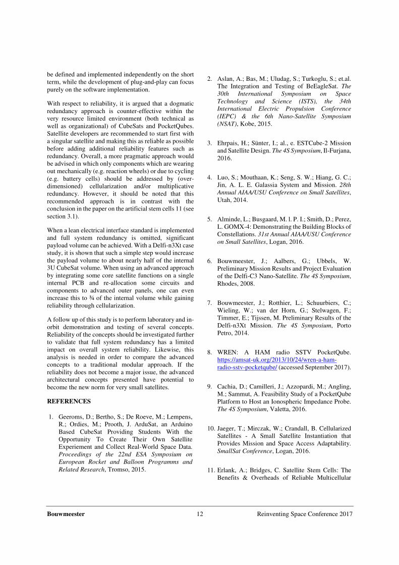
Figure 11. Delfi-n3Xt advanced concept physical
breakdown
In the advanced configuration, as shown in Figure 11
(where white boxes represented integrated components),
an integrated core unit combines the EPS control and
distribution, the OBC and the ADCS microcontroller.
There is a separate attitude actuator board, which is
slightly smaller than the full ADCS system. Battery
system and propulsion system remain unchanged.
MPPT, sun sensors and flat cellular radios are integrated
together with the solar cells on an advanced outer panel.
Magnetometers are distributed over the satellite as self-
powered wireless sensor.
The volume budgets of the internal stack are compared
in Figure 12. The effective payload volume for all
configurations is based on an internal volume of 90 mm
x 90 mm square, with a stack height of 27 mm in the
launch configuration, 165 mm in the lean configuration
and 260 mm for the advanced configuration. This proves
that significant improvement can be made in payload
volume with a lean approach and a dramatic
improvement with an advanced architecture.
Figure 12. Delfi-n3Xt volume budget with launch (I),
lean (II) and advanced (III) configuration.
6. CONCLUSIONS & DISCUSSION
In this paper, several traditional and advanced
approaches with respect to the physical architecture of
PocketQubes and CubeSats have been presented and
analyzed theoretically. Cellularization of components,
integration of core subsystem functionality into a single
physical unit, an advanced outer panel and self-powered
wireless sensors are all advanced and promising
concepts. Besides advantages, each of them also have
disadvantages compared to a typical modular approach
found in CubeSats. Moreover, the advanced concepts
typically become impractical when implemented as a
dogmatic solution for the whole satellite and as such a
smart pragmatic approach is recommended. A hybrid
approach, using a mix of the traditional approach with
advanced concepts can be very useful, but it should be
noted that some concepts are not fully compatible with
each other. Plug-and-play is an interesting but not yet
mature concept. A lean electrical interface standard can
satellite
internal bus stack
integrated core unit
onboard computer
EPS control & distribution
ADCS microcontroller
data storage
bluetooth wireless transceiver
EPS batteries
propulsion systemattitude actuator
unit
advanced outer panels
sun sensor
flat celullar radio transmitter
temperature sensor
solar cells
maximum power point tracker
loose
components
thermal control tapes
rods & fasteners
self-powered wireless
magnetometers
payload
Bouwmeester 12 Reinventing Space Conference 2017
be defined and implemented independently on the short
term, while the development of plug-and-play can focus
purely on the software implementation.
With respect to reliability, it is argued that a dogmatic
redundancy approach is counter-effective within the
very resource limited environment (both technical as
well as organizational) of CubeSats and PocketQubes.
Satellite developers are recommended to start first with
a singular satellite and making this as reliable as possible
before adding additional reliability features such as
redundancy. Overall, a more pragmatic approach would
be advised in which only components which are wearing
out mechanically (e.g. reaction wheels) or due to cycling
(e.g. battery cells) should be addressed by (over-
dimensioned) cellularization and/or multiplicative
redundancy. However, it should be noted that this
recommended approach is in contrast with the
conclusion in the paper on the artificial stem cells 11 (see
section 3.1).
When a lean electrical interface standard is implemented
and full system redundancy is omitted, significant
payload volume can be achieved. With a Delfi-n3Xt case
study, it is shown that such a simple step would increase
the payload volume to about nearly half of the internal
3U CubeSat volume. When using an advanced approach
by integrating some core satellite functions on a single
internal PCB and re-allocation some circuits and
components to advanced outer panels, one can even
increase this to ¾ of the internal volume while gaining
reliability through cellularization.
A follow up of this study is to perform laboratory and in-
orbit demonstration and testing of several concepts.
Reliability of the concepts should be investigated further
to validate that full system redundancy has a limited
impact on overall system reliability. Likewise, this
analysis is needed in order to compare the advanced
concepts to a traditional modular approach. If the
reliability does not become a major issue, the advanced
architectural concepts presented have potential to
become the new norm for very small satellites.
REFERENCES
1. Geeroms, D.; Bertho, S.; De Roeve, M.; Lempens,
R.; Ordies, M.; Prooth, J. ArduSat, an Arduino
Based CubeSat Providing Students With the
Opportunity To Create Their Own Satellite
Experiement and Collect Real-World Space Data.
Proceedings of the 22nd ESA Symposium on
European Rocket and Balloon Programms and
Related Research, Tromso, 2015.
2. Aslan, A.; Bas, M.; Uludag, S.; Turkoglu, S.; et.al.
The Integration and Testing of BeEagleSat. The
30th International Symposium on Space
Technology and Science (ISTS), the 34th
International Electric Propulsion Conference
(IEPC) & the 6th Nano-Satellite Symposium
(NSAT), Kobe, 2015.
3. Ehrpais, H.; Sünter, I.; al., e. ESTCube-2 Mission
and Satellite Design. The 4S Symposium, Il-Furjana,
2016.
4. Luo, S.; Mouthaan, K.; Seng, S. W.; Hiang, G. C.;
Jin, A. L. E. Galassia System and Mission. 28th
Annual AIAA/USU Conference on Small Satellites,
Utah, 2014.
5. Alminde, L.; Busgaard, M. l. P. I.; Smith, D.; Perez,
L. GOMX-4: Demonstrating the Building Blocks of
Constellations. 31st Annual AIAA/USU Conference
on Small Satellites, Logan, 2016.
6. Bouwmeester, J.; Aalbers, G.; Ubbels, W.
Preliminary Mission Results and Project Evaluation
of the Delfi-C3 Nano-Satellite. The 4S Symposium,
Rhodes, 2008.
7. Bouwmeester, J.; Rotthier, L.; Schuurbiers, C.;
Wieling, W.; van der Horn, G.; Stelwagen, F.;
Timmer, E.; Tijssen, M. Preliminary Results of the
Delfi-n3Xt Mission. The 4S Symposium, Porto
Petro, 2014.
8. WREN: A HAM radio SSTV PocketQube.
https://amsat-uk.org/2013/10/24/wren-a-ham-
radio-sstv-pocketqube/ (accessed September 2017).
9. Cachia, D.; Camilleri, J.; Azzopardi, M.; Angling,
M.; Sammut, A. Feasibility Study of a PocketQube
Platform to Host an Ionospheric Impedance Probe.
The 4S Symposium, Valetta, 2016.
10. Jaeger, T.; Mirczak, W.; Crandall, B. Cellularized
Satellites - A Small Satellite Instantiation that
Provides Mission and Space Access Adaptability.
SmallSat Conference, Logan, 2016.
11. Erlank, A.; Bridges, C. Satellite Stem Cells: The
Benefits & Overheads of Reliable Multicellular
Bouwmeester 13 Reinventing Space Conference 2017
Architectures. IEEE Aerospace Conference, Big
Sky, 2017.
12. McNutt, C.; Vick, R.; Whiting, H.; Lyke, J.
Modular Nanosatellites - Plug-and-Play (PnP)
CubeSat. 7th Responsive Space Conference, Los
Angeles, 2009.
13. Kief, C.; Zufels, K.; Christensen, J.; Mee, J.
Trailblazer- Proof of Concept CubeSat Mission for
SPA-1. AIAA Infotech, St. Louis, 2011.
14. Bruhn, F.; Schulte, J. S. P.; Freyer, J. Njord: A Plug-
and-Play Based Fault Tolerant CubeSat
Architecture. The 4S Symposium, Portoroz, 2012.
15. Lyke, J.; Mee, J.; Bruhn, F.; Chosson, G.;
Lindegren, R.; Lofgren, H.; Schulte, J.; Cannon, S.;
Christensen, J.; Hansen, B.; Vick, R.; Calixte-
Rosengren, J. A Plug-and-play Approach Based on
the I2C Standard. 24th Annual AIAA/USU
Conference on Small Satellites, Logan, 2010.
16. Lyke, J.; Young, Q.; Christensen, J.; Anderson, D.
Lessons Learned: Our Decade in Plug-and-play for
Spacecraft. 28th Annual AIAA/USU Conference on
Small Satellites, Logan, 2014.
17. Boom, C. W. d.; Heiden, N. v. d.; Sandhu, J.;
Hakkesteegt, H. C.; Leijtens, J. L.; Nicolelet, L.;
Bouwmeester, J.; Craen, G. v.; Santandrea, S.;
Hannoteau, F. In-orbit Experience of TNO Sun
Sensors. 8th International ESA Conference on
Guidance, Navigation & Control Systems, Karlovy
Vary, 2011.
18. Llanos, J.; Bouwmeester, J. Thermoelectric
Harvesting for an Autonomous Self-Powered
Temperature Sensor in Small Satellites. 68th
International Astronautical Congress , Adelaide,
2017.
19. Bouwmeester, J.; Reijneveld, J.; Hoevenaars, T.;
Choukroun, D. Design and Verification of a Very
Compact and Versatile Attitude Determination and
Control System for the Delfi-n3Xt Nanosatellite.
The 4S Symposium, Portoroz, 2012.
20. Vergoossens, T.; Guo, J.; Bouwmeester, J.; Groen,
W. Design, Integration and Testing of World's
Smalles Satellite Reaction Wheel. International
Astronautical Congress, Adelaide, 2017.
21. NanoPower P31 (rev. 2.20); Datasheet;
GOMSpace, 2017.
22. Alminde, L.; Bisgaard, M.; Vinther, D.; Viscor, T.;
Ostergard, K. Educational Value and Lessons
Learned from the AAU-CubeSat Project.
Proceedings of the International Conference on
Recent Advances in Space Technologies, Turkey,
2003; pp 57-62.