Embed Size (px)
Citation preview
Applied Mathematical Sciences, Vol. 3, 2009, no. 29, 1407 - 1451
A Neural-Network to Solving the Output
Contention in Packet Switching Networks
A. Badi and K. Akodadi
Departement de Mathematiques et InformatiqueFaculte des sciences Ben M’sik Universite Hassan II, Mohammedia
B.P 7955, Sidi Othman, Casablanca, [email protected]
M. Mestari
E.N.S.E.T Mohammedia Avenue Hssan II Mohammedia Morocco
A. Namir
Departement de Mathematiques et InformatiqueFaculte des sciences Ben M’sik Universite Hassan II, Mohammedia
B.P 7955, Sidi Othman, Casablanca, [email protected]
Abstract
Optical packet switching based on Wavelength Division Multiplexing(WDM) offers the possibility of increased granularity and more effec-tive use bandwidth in large capacity systems, on scale of Tb/s. Thenatural integration of optical packet switching in photonic technologyopens up the possibility of packet switching in transparent optical chan-nels, where the packets remain from end-to-end in the optical domain,without the necessity of optoelectronic conversion. Therefore, the opti-cal switching must be robust enough in order to provide conditions tosolve the contention between optical packets in access networks, wherethe traffic is less aggregated. This works presents a novel approach tosolving the output contention in optical packet switching networks withsynchronous switching mode. A contention controller has been designedbased on the Order Statics Filters (OSF) neural-network technique witha speed up factor to achieve a real-time computation of a non blockingswitching high-speed high-capacity packet switch without packet loss.A neural network, OSF, which with any of binary as input, outputs
1408 A. Badi, K. Akodadi, M. Mestari and A. Namir
the Kth largest element of the array is proposed. Overall time is con-stant, and does not depend upon the size of the input array, being justeleven times the processing time for a single neuron. This neural net-work may be used as a building block for hardware implementation oforder statistic filters.
Keywords: Optical packets switching (OPS), Head-of-line (HOL), Mul-tiprotocol label switching (MPLS), Order static filter (OSF), Wavelength di-vision multiplexing (WDM), generalized multi-protocol label switching (GM-PLS), First in first out (FIFO), Pattern recognition and image processing(PRIP)
1 Introduction
Output contention is an inherent characteristic of packet switching net-works due to unscheduled arrival process of information packets. In packetswitch with synchronous switching mode, there may be up to N number ofpackets simultaneously contending for the same output port but only up toC contending packets (C is less than N) can be routed out to that outputport where C is the speed up factor of the switch. The principal tasks of thecontention controller are to select up to C contending packets for each outputport and to switch selected packets to their destined output ports. Such tasksmust be completed in less time than it takes to transmit a packet.
Neural networks have been proposed for solving the output-contentionproblem. Troudet et al. [71], Marrakchi et al. [38] have proposed the useof a Hopfield neural network for real time control of input queued crossbarswitch for switching packets at maximum throuput. Brown et al. [10] has pro-posed a neural network based on multiple overlapping winner-take-all circuitsto compute a nonblocking switching configuration for an input queued Banyanswitch with a performance of within a factor of two of the nonblocking switch.Le Nguen Binh et al. [8] have proposed K-winner neural network [75] for solv-ing the output contention in packet switching networks with switching mode.Unlike Hopfield energy functions approach or K-winer-take-all, that requiresthe researcher to first define the constraints of the problem and then go throughan imprecise and obscuring energy function to define the weights, these net-works have properties that can be directly defined and controlled. This directapproach allows efficient implementations that are scalable to large size andas long as the external inputs are within defined limits, the network will al-ways satisfy the constraints embodied in the OSF (priority). Furthermore ourproposed scheme demonstrates, through simulation, the behaviour of packetswitching with the speed up factor C. A contention controller using the OSF
Neural-network to solving output contention 1409
neural network technique is thus proposed and analysed.
In our proposal, the search for the contending C packets for size N is carriedout in 11τ time and only requires employment of N sorting networks.
In this paper, we proposed the use of OSF is a technique extensively used inpattern recognition and image processing PRIP applications [2], [13], [10], [11],[33], [41]-[53], [55], [57], [63], [67], [70], [74]. During the past decades, consider-able efforts have been devoted to developing special computer architectures forPRIP applications [5], [34], [35], [54], [61], [64], [69]. Recent advances in VeryLarge Scale Integration (VLSI) microelectronic technology have triggered theidea of implementing PRIP algorithms directly in specialized hardware chips.Many attempts have been made to develop special VLSI devices for such pur-poses. It is of certain importance and interest to develop a hardware modelof high processing speed that can be used as a building sorting and adaptiveOSF (called comparison and selection filters [33]). The main task of the OSFis to find the kth-order statistic of an input array, defined as being the kth
largest element in the array. This technique finds application in telecommu-nications particularly for controlling data packet switches [8], [9]-[12]. In [32],a member of the OSF family shows applications in VLSI auditory and visualsystems, while in [21], another filter of OSF family as an analogue decoder oferr-correcting codes is proposed. OSF are mostly implemented in software [2],[4], [20], [24], [26], [28], [36], [56], [59], [61], [70], [73], [74], whereas hardwareimplementations are designed only for specific members, particularly the me-dian and maximum filters, of the OSF family [17], [29], [41], [42], [44], [60],[66], [77].
All neural networks considered in this paper have a feed-for-ward structurewith two kinds of neurons, linear and threshold logic neurons. These networkshave a very simple configuration, the connection strengths between the neu-rons are all fixed, most of them being just +1 or -1, which makes hardwareimplementation easy and straightforward. The modularity and the regularityof the networks’ architecture make them suitable for VLSI implementation.
The processing time of each network herein proposed is constant. As thesize of the input array increase, only the number of neurons in each layerincreases, not the number of layers themselves. Therefore, the network’s totalprocessing time remains constant, irrespective of the size of the input array.This is in contrast with conventional digital hardware implementation, wherethe processing time increases along with the input size. Although constantprocessing time is achievable using unlimited fan-in logic gates, the circuit sizegrows exponentially as the size of the input increases [15], [23]. The circuit
1410 A. Badi, K. Akodadi, M. Mestari and A. Namir
size of OSF, however, only grows quadratically.
Neural networks are noted for their ability to process large amounts ofdata quickly using a copious number of highly find solutions; the multitude ofreadily available data; and the similar neural and switching network topologiesall suggest the potential for exploiting neural networks in the switching controlproblem. Finally, the significance and potential of the neural-network arediscussed and concluded.
The rest of paper is organised as follows. In section II, we describe switchingpacket. Section III is devoted to the application of the OSF in implementationof various order statistic filter, including sorting and adaptive order statisticfilters. Section IV developing a simulating system. Section V contains theconclusion.
2 Optical Packet Switching and Contention Res-
olution Problems
2.1 Background
This section will introduce some basic concepts of switching theory. Moredetailed development of switching the theory can be found in any of severalreferences, [6], [27] and [65]. We abstract a switch as a device that takes aset of N inputs and reproduces them in any permuted order at the output.We restrict our discussion to square switches, where the number of inputs andoutputs is the same, although the concepts that we develop readily generalizeto non-square switches. If the inputs and outputs of the switch are N distinctlines, then we refer to the switch as a space switch. Alternatively the switchcould one line for the input one line for the output. In this case, the inputsand outputs are N distinct blocks of data in witch the order that the block aresent is permuted by the switch. Since each time switch is equivalent to somespace switch, we will restrict our discussion to space switches.
The basic switch is the NxN crossbar switch. Conceptually, it comprisesa packet request in a general switch is a request for a connection from oneunused input to one unused output. A packet is blocked if the connectioncan not be put up through the switch. This occurs due to constraints fromthe architecture of the switch, or due to the current state of the switch. Aswitch is non-blocking if simultaneously given any legal set of packets (eachinput and output used at most once); the switch can put all of the packets. Aswitch is strictly non-blocking in any sequence of legal packet requests, with
Neural-network to solving output contention 1411
intervening packet disconnects, can be put up as each request arrives, andno matter what algorithm is used for routing packets. The NxN crossbar isthe prototypical example of the non-blocking class. While such a switch isdesirable, unfortunately it is at the expense of N2 crospoints. The crospointcount of switch is often used as measure of its cost or complexity. We desireto reduce the number of crospoints. Usually this is achieved by building largerswitches stages of smaller crossbar switches.
2.2 Contention resolution problems
WDM has been rapidly acceptance as the technology that is able to handlethe forecast dramatic increase of bandwidth demand in future networks [30].Besides the huge amounts of bandwith, all-optical WDM networks also allowhigh-speed data transmission without electronic converts at intermediate nodesand transparency with respect to data format to be achieved [62]. However,the service evolution and the rapid increase in traffic levels fuel the intereston optical packet switching resolution problem. While current applicationsof WDM focus on the fast static usage of individual WDM channels, opticalpacket switching technologies enable the fast allocation of WDM channels inan on-demand fashion with fine granularities. The challenge now is to combinethe advantages of the relatively coarse-grained WDM techniques with emergingwith optical switching capabilities to yield a high-throughput optical platform.
A further reason leading to optical packet switching is its intrinsic flexibil-ity to cheaply support incremental increase of the transmission bit rate [68].One of the key problems in application of packet switching in optical domain isthe handling of packet contention that take place when two or more incomingpackets are directed to the same output line. Contention can be solved in thefollowing three ways; 1) by dropping the contending packet; 2) by deflectingthe contending packet to another part of wavelength; 3) by buffering the con-tending packet (using delay lines or using electronic memory) until the outputport is free. Of these three, only buffering offers an immediate solution as1) port deflection is undesirable because it is in general not compatible withend-to end requirements as implemented in Generalized Multi-Protocol LabelSwitching (GMPLS) [7]; 2) by dropping the contending packet is obviouslythe poorest strategy, as it relies on the higher level protocols in retransmittingissues. Thus, buffering does not have any of the above mentioned drawbacksand moreover enables the prioritization of traffic based on, e.g., the differen-tiated services (DiffServ) specification [58]. The drawback of buffering is theintroduction of additional delay and jitter in the network.
1412 A. Badi, K. Akodadi, M. Mestari and A. Namir
2.3 A novel approach to solving the output contentionin packet switching networks
Output contention occurs when there are more than one (up to N) HOL pack-ets from the input ports simultaneously requesting to be switched to the sameoutput port. Only C of these contending packets can be routed to the sameoutput port. The remaining of the contending packets have to wait for thenext transmission cycle to compete again. The approach taken in resolvingthe output-contention problem and selecting up to C packets for each outputport depends on the service selection policy employed by the packet switch.Typical service selections policies are the random selection policy, FIFO se-lection policy, longest queue selection policy, and customer priority selectionpolicy. In packet transmission and switching, the sequence of the packets astransmitted by the customers must be maintained. This means that only theHOL packets in all the input buffers can compete in the selection process.The random selection policy stipulates that up to C packets can be routed tothe same output port on a random basis with each of the contending packetshaving the equal probability of being selected. FIFO selection policy, on theother hand, dictates that packets which appear at the HOL positions at a giventime slot that are destined for the same output are transferred before all thepackets which appear at the HOL positions at the subsequent time slots withthe same output destination. If there are several packets with the same arrivaltime, random selection is made between these packets. In the longest queueselection policy, the packet from the longest input queue is sent first. If thereare several queues with the same maximum length, random selection is madebetween these contending packets. Under the customer priority selection pol-icy, the higher priority packets are serviced ahead of the lower priority packets.This service selection policy is particularly important with regard to servicesthat have a stringent delay requirement.
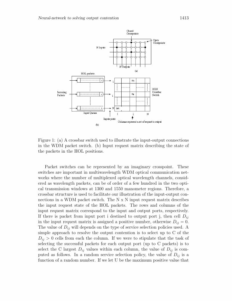
Our novel approach to resolving the output contention and implement-ing the service-selection policy is best described by to referring to figure. 1.Which shows how a request for packet transmission through an N x N cross-bar can be mapped onto an N x N input request matrix. Each input andoutput connection of the nonblocking optoelectronic WDM or Time DivisionMultiplexing(TDM).
Neural-network to solving output contention 1413
Figure 1: (a) A crossbar switch used to illustrate the input-output connectionsin the WDM packet switch. (b) Input request matrix describing the state ofthe packets in the HOL positions.
Packet switches can be represented by an imaginary crosspoint. Theseswitches are important in multiwavelength WDM optical communication net-works where the number of multiplexed optical wavelength channels, consid-ered as wavelength packets, can be of order of a few hundred in the two opti-cal transmission windows at 1300 and 1550 manometer regions. Therefore, acrossbar structure is used to facilitate our illustration of the input-output con-nections in a WDM packet switch. The N x N input request matrix describesthe input request state of the HOL packets. The rows and columns of theinput request matrix correspond to the input and output ports, respectively.If there is packet from input port i destined to output port j, then cell Dij
in the input request matrix is assigned a positive number, otherwise Dij = 0.The value of Dij will depends on the type of service selection policies used. Asimple approach to resolve the output contention is to select up to C of theDij > 0 cells from each the column. If we were to stipulate that the task ofselecting the successful packets for each output port (up to C packets) is toselect the C largest Dij values within each column, the value of Dij is com-puted as follows. In a random service selection policy, the value of Dij is afunction of a random number. If we let U be the maximum positive value that
1414 A. Badi, K. Akodadi, M. Mestari and A. Namir
Dij can take, then under the random service selection policy Dij = r, wherer is a random number in the range 0 < r < U , the value of Dij is a function(denoted by f) of two variables
Dij(FIFO) = f(waiting time, random number r)Dij(longest queue) = f(queue length, random number r)Dij(packet priority) = f(priority level, random number r).
The random number r is included to take into account the possibility ofpackets having the same waiting time, queue length, or priority level. Themaximum contribution of the random number to the value of Dij must notexceed the minimum contribution from the waiting time, queue length, orpacket priority. Therefore, the matrix cell value is given by
Dij = Ps.Mult + r
Where Ps is the (HOL) packet’s parameter as determined by the service dis-cipline, Mult is a multiplier, and r is a random number. The random number,r is bounded by 0 < r < Mult. The matrix cell value, Dij , is bounded by0 < Dij ≤ U . The maximum value of r, i.e., Mult must be made as large aspossible to reduce the probability of having packets with the same value of Ps
and in the same column from having the same value of r. There is, however,a constraint placed on the value Mult, i.e., Mult ≤(maximum value of Ps). Ifsuch a possibility occurs, a random selection is made among them. For eachcolumn, the packet with the largest Dij value is the first to be transmitted totheir destined output ports.
The computation of this nonblocking connection configuration must becompleted in less time than it takes to transmit a packet. The length of timeallowed is determined by the packet length and the transmission bit rate, T= L/B where T is the packet duration, L is the packet length and B is thetransmission bit rate. With an Asynchronous Transfer Mode (ATM) cell of 53bytes and a bit rate of Gigabits/s, the packet duration is about 424 ns.
3 The OSF neural network for solving the
contention problem
In this section, we develop the basic neural network, OSF, which is essentialfor construction of all neural networks herein proposed, but first, we describethe neurons employed here.
Neural-network to solving output contention 1415
3.1 Neurons Used
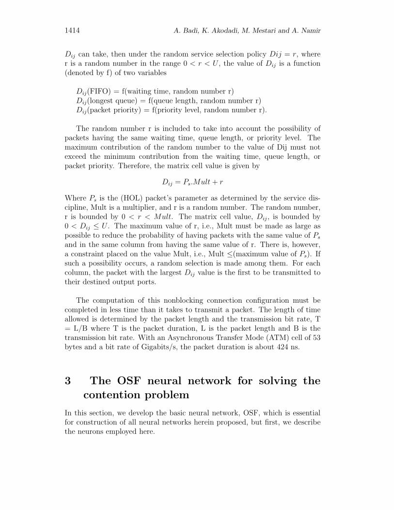
OSF employs two kinds of neurons, both of which are commonly used in neuralnetwork applications [22], [31], [37], [41]-[53]. The only difference networkbetween the two is in their activation function: one employs linear activationfunction and the other threshold-logic activation function. Their schematicrepresentations are shown in Fig. 2(b), where y is the output. These twokinds of neurons sum the n weighted inputs and pass the result through anonlinearity according to
y = φ(i=1∑n
ωixi − θ)
Where θ is a limiting or nonlinear transfer characteristic, called an activa-tion function; θ(θ ∈ R) is the external threshold, also called an offset or bias,ωi are the synaptic weights or strengths; xi are the inputs (i=1, 2,...n), n isthe number of inputs, and y represents the output [cf. Fig. 2(a)].
The threshold-logic neuron model [see Fig. 2(b)] uses only the binary (hardlimiting) function [see Fig. 2(c)]. In this model, a weighted sum of all inputsis compared with a threshold θ . If this sum exceeds the threshold, the neuronoutput is set to ’high value’ or to ’low value’ according to the equation
φ(x) =
{1, ifx ≥ 00, otherwise
Where x =∑n
i=1 ωixi − θx, and is the threshold-logic activation functionor binary activation function [cf. Fig. 2(c)].
In the case of the linear activation function [see Fig. 2(b)], the output y isgiven by φL(x) = x Where φL is the linear activation function [see Fig. 2(c)]defined by φL(x) = x with x =
∑ni=1 ωi(x) Both kinds of neurons, threshold
and linear, have already been implemented in the past using analog electronic[16], [25].
3.2 Some Basic Functions
In this subsection, we introduce special functions that are essential for con-struction. First, however, we give the representation employed to representthe element of input array X.
1416 A. Badi, K. Akodadi, M. Mestari and A. Namir
With a view to making the neural models proposed in this paper adaptableand to then facilitate their incorporation into digital calculators, we will employthe coding used in the majority of present-day computers to represent theelements of input array X.
Let Xi be an element of the input array X(i = 1, 2, ..., N). Each elementXi of X is represented in a single way by the triplet (SXi
,MXi,EXi
), as follows:
Xi = SXiMXi
2EXi
Where
• SXi, designating the sign of Xi is coded on 1 bit (SXi
= 0 if Xi is positiveor zero, and SXi
= 1 otherwise);
• MXi, designating the mantissa normalized to m digits is coded on m bits
(MXi, is a real number: (1
2≤ MXi
)π1);
• EXidesignating the exponent is coded on p bits (EXi
is a positive, neg-ative, or zero integer).
The mantissa normalized to m digits MXiis represented in (binary) base 2
by
MXi=
j∑j=1
M jXi
2−j
Where M jXi
(j = 1, 2, ..., m) are the digits of mantissa MXiin base 2.
M jXi
∈ {0, 1} for 1 ≤ j ≤ m and 1 ≤ i ≤ N .Agreeing that (1
2) ≤ MXi
implies M1Xi
= 1 .The exponent EXi
, is coded in the form ’arithmetic complemented to 2’(necessary to encode the negative exponent)
EXi=
p−2∑j=0
EjXi
− SEXi2p−1(11)
Where SEXi= 1 is the sign bit of EXi
(SXi= 0 if EXi
is positive or zero,and, SEXi
= 1 otherwise), and EXi∈ {0, 1} for 0 ≤ j ≤ p − 1 and 1 ≤ i ≤ N .
The exponent EXi, given by (11), may be calculated by a single neuron
(cf. Fig. 4). We can then represent any element Xi of the input array X as a(m+p+1) bit binary number, as follows:
Xi = (SXi, M1
Xi, M2
Xi, ..., Mm
Xi, SEXi
, E0Xi
, E1Xi
, .., Ep−2Xi
)(12)
Neural-network to solving output contention 1417
The task of finding the kth largest element of the input array X can be donein two phases.
1/ Compute the order in the input array X of any element Xq(q = 1, 2, ..., N).
2/ Select and transfer to output the element of the input array X corre-sponding to the order k desired or chosen by decision-markers (designers).
Note that the operation in either of these two phases can be performed inparallel. This is why it is possible to achieve high processing speed by utilizingthe massive parallelism of neural networks.
Corresponding to these two phases, the OSF is composed of N order net-works, a selection network, and an adjustment input, which allows choice ofthe order k of the element input, which allows choice of the order k of theelement to be transferred to output.
3.3 Order and Selection Networks
The function of the order network ONq, (1 ≤ q ≤ N) is to compute the orderin the input array X of each element Xq [41]-[53]. The order network ONq
computes the order function (17) and is made up of (N-1) comparison networks,CNi,q i ∈ {1, 2, ..., N} − {q}, as shown in Fig. 6.
The function of the selection network is to select from among the elementsof input array X the element corresponding to the order fixed by the adjustmentinput and to transfer it to output. This network is composed of N EqualityNetworks (ENs) and a Detection Network (DN), which will be studied here-after.
1/ Equality Network: The EN determines whether the order of an elementis equal or not to a given number k. The number k(1 ≤ k ≤ N) is fixed viathe adjustment input , according to the formula
k =
n−1∑q=0
aq(k)2
q
Where a0(k), a
1(k), ..., a
n−1(k) is the word of command allowing choice of the
order of the element to be sent to output. aq(k) ∈ {0, 1} for 1 ≤ q ≤ n − 1 and
1418 A. Badi, K. Akodadi, M. Mestari and A. Namir
1 ≤ k ≤ N
The function computed by the EN is defined as
eq[ord(Xi, X), k] =
{0, iford(Xi, X) = k1, otherwise
3.4 The OSF
The OSF is shown in Fig. 12, where the adjustment input Ak determineswhich order statistic is to appear at the output. The network illustrated inFig. 11 consists of two kinds of neurons arranged in 11 layers. The numberof neurons in OSF for input size N is 14N2 + (m + p − 9)N + m + p + 2. There are 11 layers of neurons in the OSF, thus the processing time is 11times the processing time of a single neuron. As the number of elements ofthe input array increases, only the number of neurons in each layer increases,not the number of layers themselves. Therefore, OSF total processing timeremains constant irrespective of the number of element in the input array.This contrasts with conventional hardware implementation of order statisticfilters [14], [72], where the processing time increases along with the number ofelements.
The claim that the processing speed of OSF is independent of its input sizedoes not take into account limitations in the hardware implementation. It isbased on the assumption that the processing time of a neuron is independentof its input size. This assumption, however, is not true in analog circuits. Forinstance, as the number of inputs to neuron increases, the capacitances of thewires that connect these inputs will increase, causing the settling time to therequired accuracy to increase. Therefore, the processing speed of the OSF tosome extent depends on the input size. Even with these limitations, however,the processing speed of the OSF will still be high enough to have the advantageof speed.
Technologies used in OSF implementation are broadly categorized into sil-icon [19], [39]-[40] using analog, digital, or mixed analog/digital integratedcircuits, and optical or electroptical [1], [3]. No matter which medium is used,the performance of the OSF would inevitably be affected by the current levelof the medium’s technology. Here, we address some problems that might befaced when the OSF is implemented using analog VLSI circuits. Such prob-lems are also common to other neural network models; however, because theOSF has a simple configuration, its implementation is less affected.
Neural-network to solving output contention 1419
The first problem is that of poor absolute accuracy is setting up the valuesof the connection weights. This problem does not arise if the OSF is imple-mented using monolithic analog VLSI circuits.
Whatever technology is utilized, the OSF is not affected by this problem,since the OSF has a very simple configuration, its weights are all fixed, andmost of them are just +1 or -1; they can be set simply by connecting the inputto the neuron or by inverting the input before connection.
The second problem is due to the saturation characteristics of the amplifierused in implementing the linear neuron. For some practical applications, thismay not be a serious problem [41]-[53].
For example, in image processing applications, the input to the OSF canbe easily scaled to fit in the linear range of the amplifier.
4 Simulation and results
The task of the OSF, however, is to select the C or less than C largest Dij
values [8], from each column in the HOL input request matrix if there aremore than C packets contending for the same time or in the case that therefewer than time respectively. Each input port controller computes de valueof Dij of its HOL packets and transmits this value together with the HOLpacket’s output port destination address to the input interface of the neuralnetwork contention controller. Based on the output port destination address,each input interface is affected the equivalent value of Dij .
Let us now describe the interface between the neural network contentioncontroller and the output port controller. With up to C packets being selectedfrom each output port, the packet with the larger Dij value must be transmit-ted ahead of the packets with lower Dij value. This can be achieved by usingthe order preserving characteristic of the OSF.
In this subsection, we introduce special functions that are essential forconstruction. First, however, we give the representation employed to representthe elements of input D.
With a view to making the neural models proposed in this paper adaptableand the to then facilitate their incorporation into digital calculators, we willemploy the coding used in the majority of present-day computers to present
1420 A. Badi, K. Akodadi, M. Mestari and A. Namir
the elements of input array D.
Let Dij be an element of the input array Dij(i = 1, 2, ..., N)
Each element Dij of D is represented in a single way by the triplet (SDij, MDij
, EDij),
as follows: Dij = SDijMDij
2EDij
Where
• SDij, designating the sign of Dij is coded on 1 bit ( SDij
= 0 if Dij ispositive or zero, and SDij
= 1 otherwise);
• MDij, designating the mantissa normalized to m digits is coded on m bits
(MDij, is a real number: (1
2≤ MDij
)π1);
• EDijis a positive, negative, or zero integer.
The mantissa normalized to m digits MDij, is represented in (binary) base 2
by.
MDij=
m∑p=1
MpDij
2−p
Where MpDij
(p = 1, 2, ..., m) are the digits of mantissa MDijin base 2 Mp
Dij∈
{0, 1} for 1 ≤ p ≤ m and 1 ≤ i ≤ N .Agreeing that 1
2≤ MDij
implies M1Dij
�= 0, i.e, M1Dij
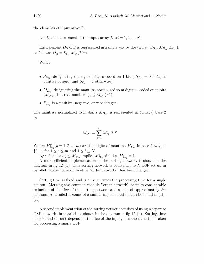
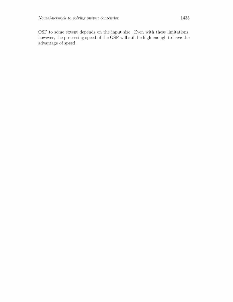
= 1.A more efficient implementation of the sorting network is shown in the
diagram in fig 12 (a). This sorting network is equivalent to N OSF set up inparallel, whose common module ”order networks” has been merged.
Sorting time is fixed and is only 11 times the processing time for a singleneuron. Merging the common module ”order network” permits considerablereduction of the size of the sorting network and a gain of approximately N3
neurons. A detailed account of a similar implementation can be found in [41]-[53].
A second implementation of the sorting network consists of using n separateOSF networks in parallel, as shown in the diagram in fig 12 (b). Sorting timeis fixed and doesn’t depend on the size of the input, it is the same time takenfor processing a single OSF.
Neural-network to solving output contention 1421
A third implementation is the use of a single OSF network [cf. fig. 12 (c)].By changing the value of k from 1 to N, the elements of the array will appearat the output sequentially. The advantage is that less neurons are needed; thedisadvantage is that the sorting time is proportional to the size of the input.
At each clock pulse [cf. fig. 12(c)], the counter changes state, and k goesfrom one value to the next. The OSF finally produces at its out put the inputarray element whose order corresponds to new value of k. the clock frequencymust be lower than OSF processing speed, i.e, lower than ( 1
(11τ)), where τ is
the processing time for a single neuron.
The hardware implementation of the continuous OSF can be designed elec-tronically using the VLSI technology wile the interactive activation OSF net-work is more suitably implemented through optoelectronic means as the statesof the neurons are updated synchronously and discretely.
The simulation is limited to N=5, C=3 and 1 column (each column iscomputed independently).
4.1 Simulation and OSF
1422 A. Badi, K. Akodadi, M. Mestari and A. Namir
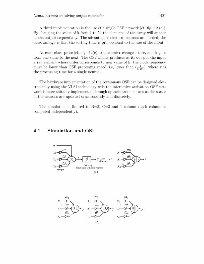
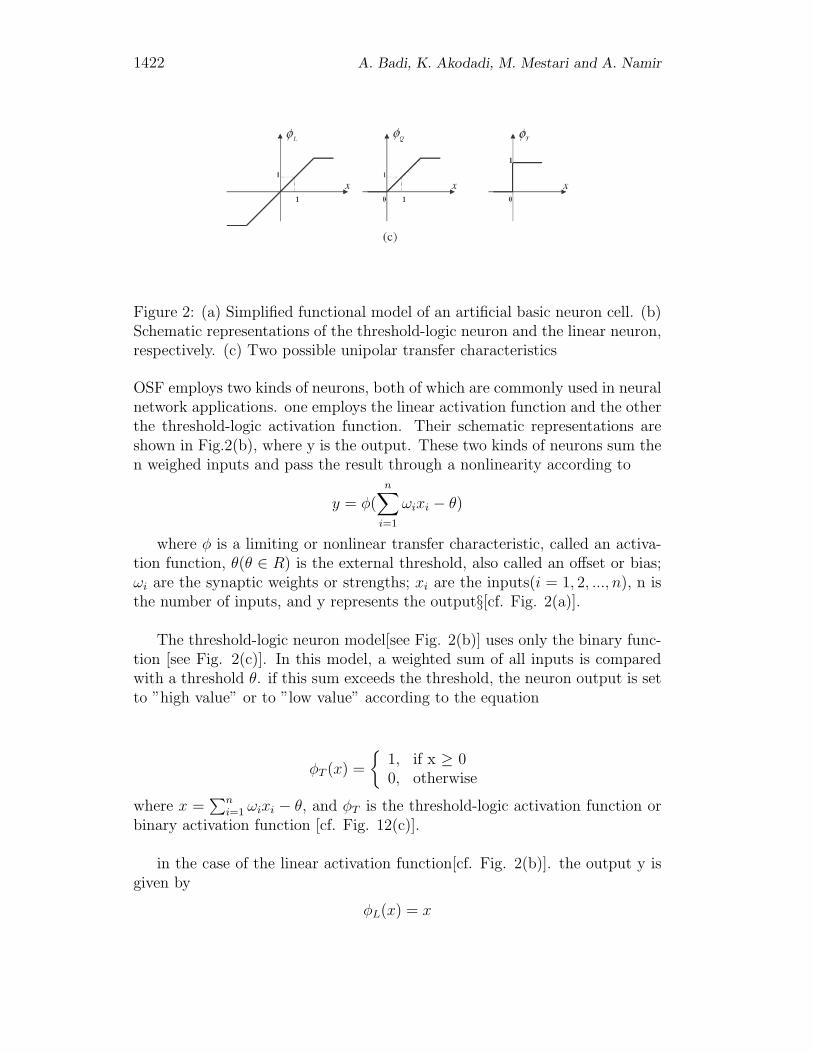
Figure 2: (a) Simplified functional model of an artificial basic neuron cell. (b)Schematic representations of the threshold-logic neuron and the linear neuron,respectively. (c) Two possible unipolar transfer characteristics
OSF employs two kinds of neurons, both of which are commonly used in neuralnetwork applications. one employs the linear activation function and the otherthe threshold-logic activation function. Their schematic representations areshown in Fig.2(b), where y is the output. These two kinds of neurons sum then weighed inputs and pass the result through a nonlinearity according to
y = φ(n∑
i=1
ωixi − θ)
where φ is a limiting or nonlinear transfer characteristic, called an activa-tion function, θ(θ ∈ R) is the external threshold, also called an offset or bias;ωi are the synaptic weights or strengths; xi are the inputs(i = 1, 2, ..., n), n isthe number of inputs, and y represents the output§[cf. Fig. 2(a)].
The threshold-logic neuron model[see Fig. 2(b)] uses only the binary func-tion [see Fig. 2(c)]. In this model, a weighted sum of all inputs is comparedwith a threshold θ. if this sum exceeds the threshold, the neuron output is setto ”high value” or to ”low value” according to the equation
φT (x) =
{1, if x ≥ 00, otherwise
where x =∑n
i=1 ωixi − θ, and φT is the threshold-logic activation function orbinary activation function [cf. Fig. 12(c)].
in the case of the linear activation function[cf. Fig. 2(b)]. the output y isgiven by
φL(x) = x
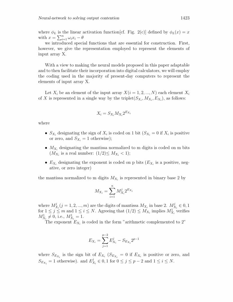
Neural-network to solving output contention 1423
where φL is the linear activation function[cf. Fig. 2(c)] defined by φL(x) = xwith x =
∑ni=1 ωixi − θ
we introduced special functions that are essential for construction. First,however, we give the representation employed to represent the elements ofinput array X.
With a view to making the neural models proposed in this paper adaptableand to then facilitate their incorporation into digital calculators, we will employthe coding used in the majority of present-day computers to represent theelements of input array X.
Let Xi be an element of the input array X(i = 1, 2, ..., N) each element Xi
of X is represented in a single way by the triplet(SXi, MXi
, EXi), as follows:
Xi = SXiMXi
2EXi
where
• SXidesignating the sign of Xi is coded on 1 bit (SXi
= 0 if Xi is positiveor zero, and SXi
= 1 otherwise);
• MXidesignating the mantissa normalized to m digits is coded on m bits
(MXiis a real number: (1/2)≤ MXi
< 1);
• EXidesignating the exponent is coded on p bits (EXi
is a positive, neg-ative, or zero integer)
the mantissa normalized to m digits MXiis represented in binary base 2 by
MXi=
n∑i=1
M jXi
2EXi
where M jXi
(j = 1, 2, ..., m) are the digits of mantissa MXiin base 2. M j
Xi∈ 0, 1
for 1 ≤ j ≤ m and 1 ≤ i ≤ N . Agreeing that (1/2) ≤ MXiimplies M1
Xiverifies
M1Xi
�= 0, i.e., M1Xi
= 1.The exponent EXi
is coded in the form ”arithmetic complemented to 2”
EXi=
p−2∑j=1
EjXi
− SEXi2p−1
where SEXiis the sign bit of EXi
(SEXi= 0 if EXi
is positive or zero, and
SEXi= 1 otherwise). and Ej
Xi∈ 0, 1 for 0 ≤ j ≤ p − 2 and 1 ≤ i ≤ N .
1424 A. Badi, K. Akodadi, M. Mestari and A. Namir
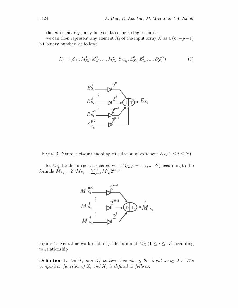
the exponent EXi, may be calculated by a single neuron.
we can then represent any element Xi of the input array X as a (m+p+1)bit binary number, as follows:
Xi ≡ (SXi, M1
Xi, M2
Xi, ..., Mm
Xi, SEXi
, E0Xi
, E1Xi
, ..., Ep−2Xi
) (1)
Figure 3: Neural network enabling calculation of exponent EXi(1 ≤ i ≤ N)
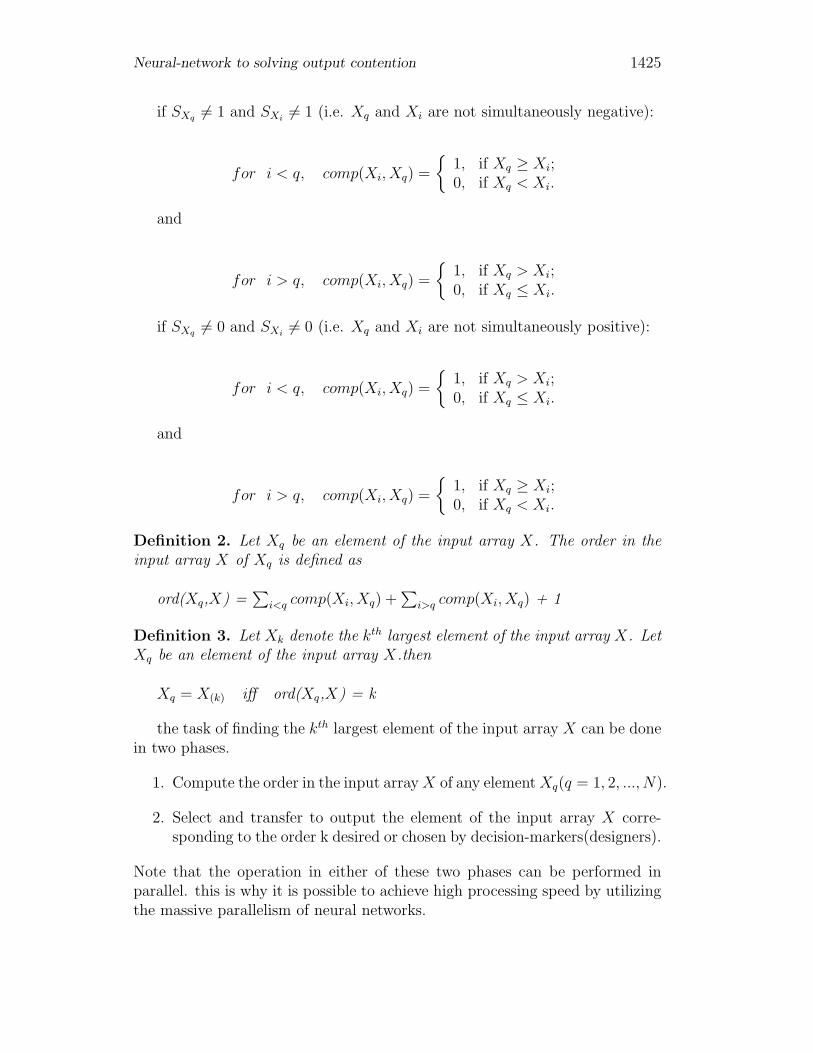
let MXibe the integer associated with MXi
(i = 1, 2, ..., N) according to theformula MXi
= 2mMXi=
∑mj=1 M j
Xi2m−j
Figure 4: Neural network enabling calculation of MXi(1 ≤ i ≤ N) according
to relationship
Definition 1. Let Xi and Xq be two elements of the input array X. Thecomparison function of Xi and Xq is defined as follows.
Neural-network to solving output contention 1425
if SXq �= 1 and SXi�= 1 (i.e. Xq and Xi are not simultaneously negative):
for i < q, comp(Xi, Xq) =
{1, if Xq ≥ Xi;0, if Xq < Xi.
and
for i > q, comp(Xi, Xq) =
{1, if Xq > Xi;0, if Xq ≤ Xi.
if SXq �= 0 and SXi�= 0 (i.e. Xq and Xi are not simultaneously positive):
for i < q, comp(Xi, Xq) =
{1, if Xq > Xi;0, if Xq ≤ Xi.
and
for i > q, comp(Xi, Xq) =
{1, if Xq ≥ Xi;0, if Xq < Xi.
Definition 2. Let Xq be an element of the input array X. The order in theinput array X of Xq is defined as
ord(Xq,X) =∑
i<q comp(Xi, Xq) +∑
i>q comp(Xi, Xq) + 1
Definition 3. Let Xk denote the kth largest element of the input array X. LetXq be an element of the input array X.then
Xq = X(k) iff ord(Xq,X) = k
the task of finding the kth largest element of the input array X can be donein two phases.
1. Compute the order in the input array X of any element Xq(q = 1, 2, ..., N).
2. Select and transfer to output the element of the input array X corre-sponding to the order k desired or chosen by decision-markers(designers).
Note that the operation in either of these two phases can be performed inparallel. this is why it is possible to achieve high processing speed by utilizingthe massive parallelism of neural networks.
1426 A. Badi, K. Akodadi, M. Mestari and A. Namir
Let | Xi | denote the absolute value of Xi; | Xi | is represented by givencouple (MXi
, EXi) as follows:
Xi = MXi2EXi
| Xi | can be represented as an (m+p) bit binary number
| Xi |≡ (M1Xi
, M2Xi
, ..., MmXi
, SEXi, E0
Xi, E1
Xi, ..., Ep−2
Xi)
Definition 4. Let | Xi | and | Xq | be the absolute value of Xi and Xq,respectively; we say that | Xq |>| Xi | if and only if
1. EXq > EXior
2. EXq = EXiand MXq > MXi
Definition 5. Let | Xi | and | Xq | be the absolute value of Xi and Xq,respectively. Then
comp(| Xi |, | Xq |) =
{S1, if i < q ;S2, if i > q .
where
S1 = φT [φT (EXq − EXi− 1) − φT (EXi
− EXq − 1) + φT (−φT (EXq − EXi− 1)−
φT (EXi− EXq − 1) + φT (MXq − MXi
− 1) − 1) − φT (−φT (EXq − EXi− 1)−
φT (EXi− EXq − 1) + φT (MXi
− MXq − 1) − 1) + φT (φT (−φT (MXq − MXi− 1)−
φT (MXi− MXq − 1)) − φT (EXq − EXi
− 1) − φT (EXi− EXq − 1) − 1)]
S2 = φT [φT (EXq − EXi− 1) − φT (EXi
− EXq − 1) + φT (−φT (EXq − EXi− 1)−
φT (EXi− EXq − 1) + φT (MXq − MXi
− 1) − 1) − φT (−φT (EXq − EXi− 1)−
φT (EXi− EXq − 1) + φT (MXi
− MXq − 1) − 1) − 1)]
Definition 6. Let | Xi | and | Xq | be the absolute value of Xi and Xq,respectively; we say that | Xq |>| Xi | if and only if
Neural-network to solving output contention 1427
1. SXq = 0 and SXq = 1 or
2. SXq = 0 and SXq = 0 and | Xq |>| Xi | or
3. SXq = 1 and SXi= 1 and | Xq |<| Xi |
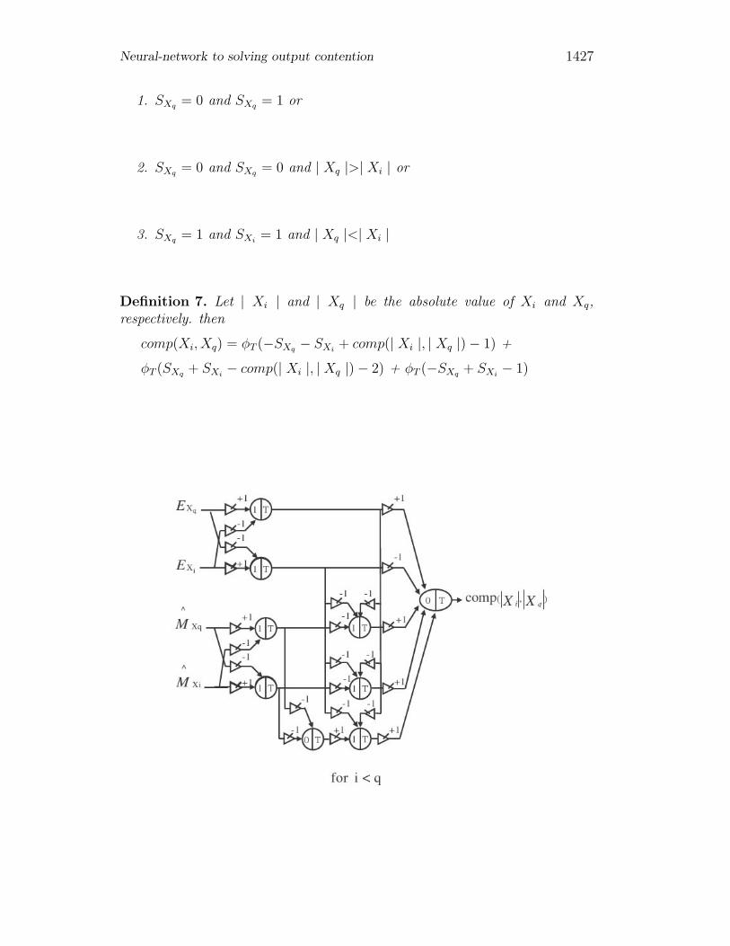
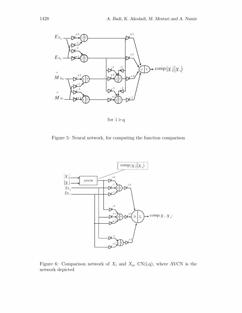
Definition 7. Let | Xi | and | Xq | be the absolute value of Xi and Xq,respectively. then
comp(Xi, Xq) = φT (−SXq − SXi+ comp(| Xi |, | Xq |) − 1) +
φT (SXq + SXi− comp(| Xi |, | Xq |) − 2) + φT (−SXq + SXi
− 1)
1428 A. Badi, K. Akodadi, M. Mestari and A. Namir
Figure 5: Neural network, for computing the function comparison
Figure 6: Comparison network of Xi and Xq, CN(i,q), where AVCN is thenetwork depicted
Neural-network to solving output contention 1429
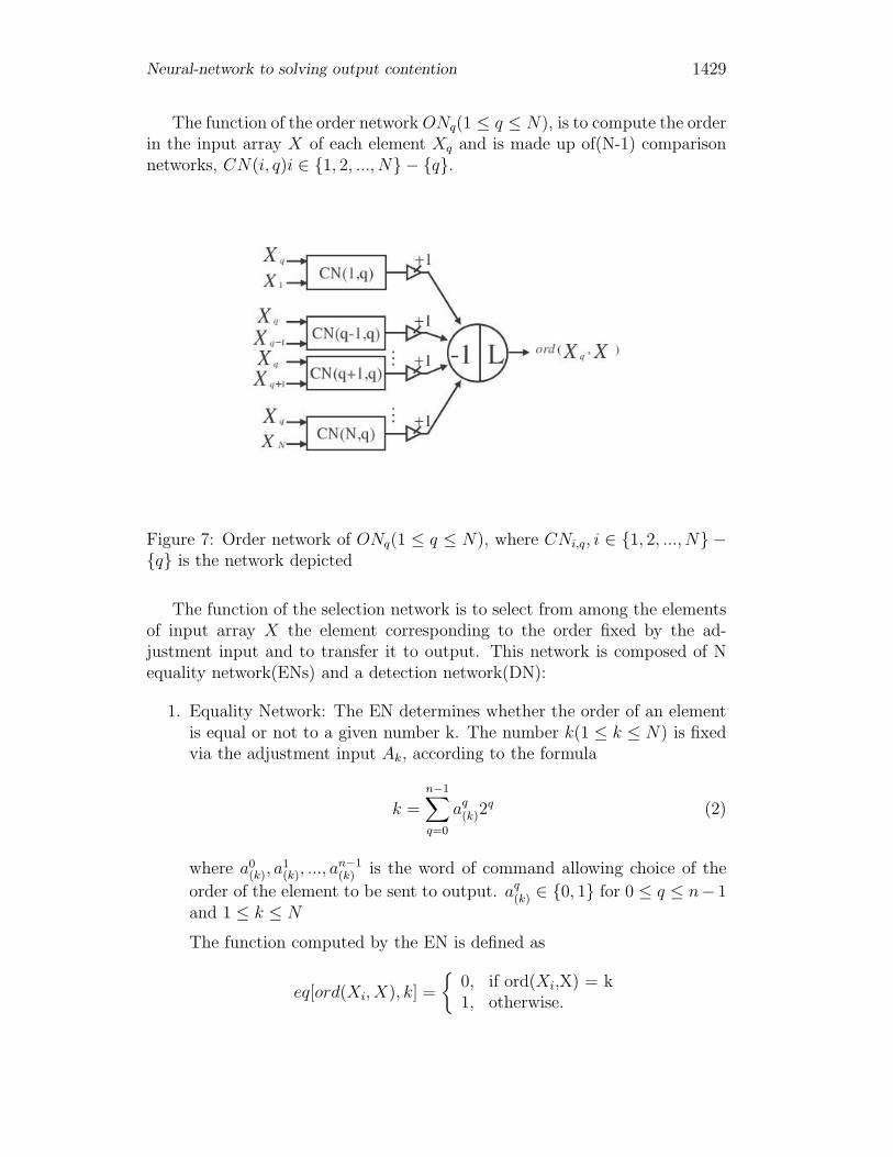
The function of the order network ONq(1 ≤ q ≤ N), is to compute the orderin the input array X of each element Xq and is made up of(N-1) comparisonnetworks, CN(i, q)i ∈ {1, 2, ..., N} − {q}.
Figure 7: Order network of ONq(1 ≤ q ≤ N), where CNi,q, i ∈ {1, 2, ..., N} −{q} is the network depicted
The function of the selection network is to select from among the elementsof input array X the element corresponding to the order fixed by the ad-justment input and to transfer it to output. This network is composed of Nequality network(ENs) and a detection network(DN):
1. Equality Network: The EN determines whether the order of an elementis equal or not to a given number k. The number k(1 ≤ k ≤ N) is fixedvia the adjustment input Ak, according to the formula
k =
n−1∑q=0
aq(k)2
q (2)
where a0(k), a
1(k), ..., a
n−1(k) is the word of command allowing choice of the
order of the element to be sent to output. aq(k) ∈ {0, 1} for 0 ≤ q ≤ n− 1
and 1 ≤ k ≤ N
The function computed by the EN is defined as
eq[ord(Xi, X), k] =
{0, if ord(Xi,X) = k1, otherwise.
1430 A. Badi, K. Akodadi, M. Mestari and A. Namir
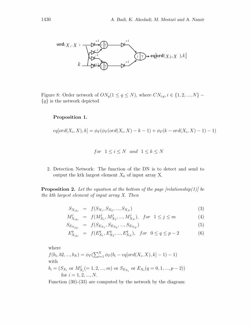
Figure 8: Order network of ONq(1 ≤ q ≤ N), where CNi,q, i ∈ {1, 2, ..., N} −{q} is the network depicted
Proposition 1.
eq[ord(Xi, X), k] = φT (φT (ord(Xi, X) − k − 1) + φT (k − ord(Xi, X) − 1) − 1)
for 1 ≤ i ≤ N and 1 ≤ k ≤ N
2. Detection Network: The function of the DN is to detect and send tooutput the kth largest element Xk of input array X.
Proposition 2. Let the equation at the bottom of the page [relationship(1)] bethe kth largest element of input array X. Then
SX(k)= f(SX1, SX2 , ..., SXN
) (3)
M jX(k)
= f(M jX1
, M jX2
, ..., M jXN
), for 1 ≤ j ≤ m (4)
SEX(k)= f(SEX1
, SEX2, ..., SEXN
) (5)
EqX(k)
= f(EqX1
, EqX2
, ..., EqXN
), for 0 ≤ q ≤ p − 2 (6)
where
f(b1, b2, ..., bN) = φT (∑N
i=1 φT (bi − eq[ord(Xi, X), k] − 1) − 1)
with
bi = (SXior M j
Xi(= 1, 2, ..., m) or SEXi
or EXi(q = 0, 1, ..., p − 2))
for i = 1, 2, ..., N.
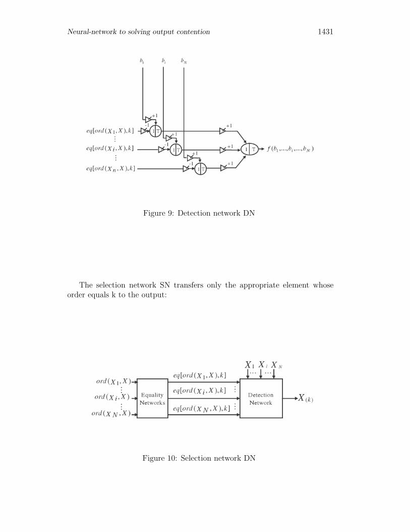
Function (30)-(33) are computed by the network by the diagram:
Neural-network to solving output contention 1431
Figure 9: Detection network DN
The selection network SN transfers only the appropriate element whoseorder equals k to the output:
Figure 10: Selection network DN
1432 A. Badi, K. Akodadi, M. Mestari and A. Namir
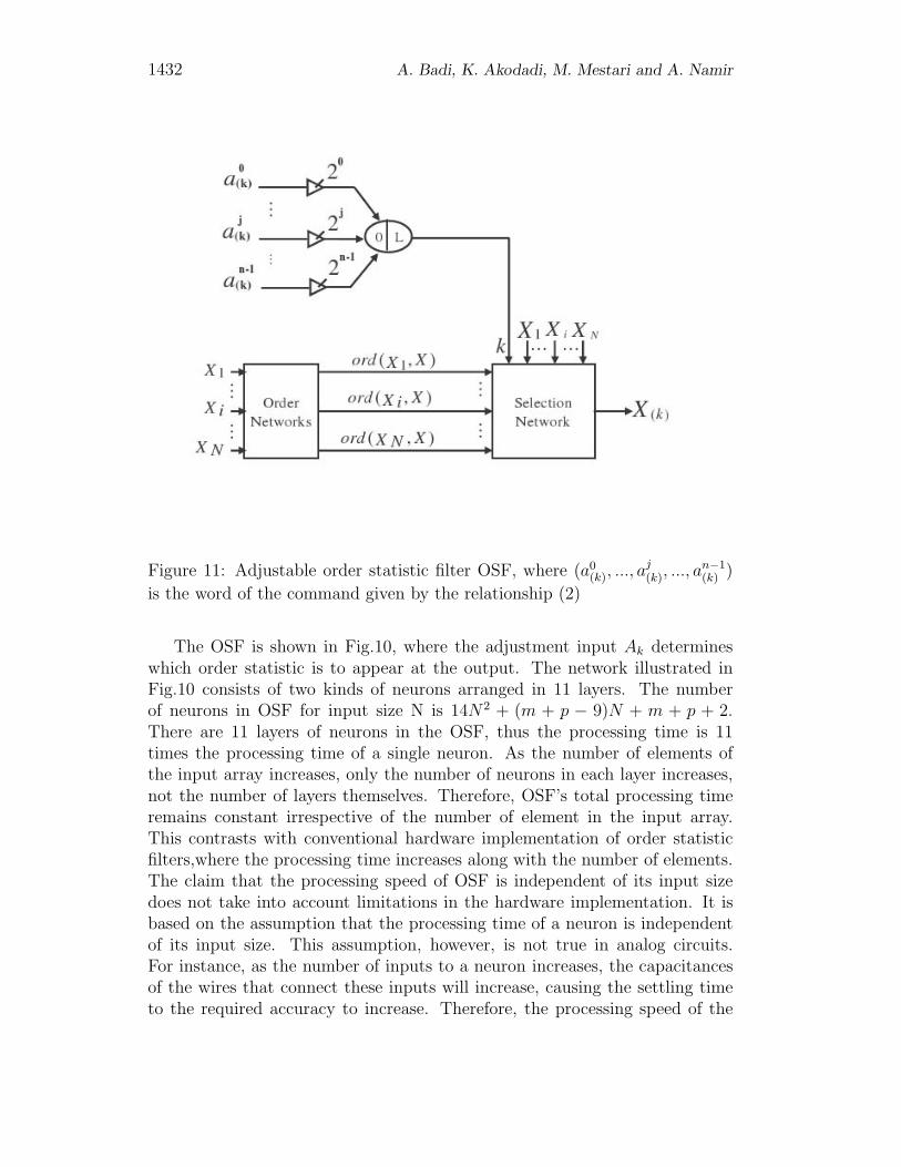
Figure 11: Adjustable order statistic filter OSF, where (a0(k), ..., a
j(k), ..., a
n−1(k) )
is the word of the command given by the relationship (2)
The OSF is shown in Fig.10, where the adjustment input Ak determineswhich order statistic is to appear at the output. The network illustrated inFig.10 consists of two kinds of neurons arranged in 11 layers. The numberof neurons in OSF for input size N is 14N2 + (m + p − 9)N + m + p + 2.There are 11 layers of neurons in the OSF, thus the processing time is 11times the processing time of a single neuron. As the number of elements ofthe input array increases, only the number of neurons in each layer increases,not the number of layers themselves. Therefore, OSF’s total processing timeremains constant irrespective of the number of element in the input array.This contrasts with conventional hardware implementation of order statisticfilters,where the processing time increases along with the number of elements.The claim that the processing speed of OSF is independent of its input sizedoes not take into account limitations in the hardware implementation. It isbased on the assumption that the processing time of a neuron is independentof its input size. This assumption, however, is not true in analog circuits.For instance, as the number of inputs to a neuron increases, the capacitancesof the wires that connect these inputs will increase, causing the settling timeto the required accuracy to increase. Therefore, the processing speed of the
Neural-network to solving output contention 1433
OSF to some extent depends on the input size. Even with these limitations,however, the processing speed of the OSF will still be high enough to have theadvantage of speed.
1434 A. Badi, K. Akodadi, M. Mestari and A. Namir
Figure 12: (a) Sorting network made up of N OSF networks in parallel whosecommon module ”order networks” has been merged (b)Sorting network madeup of N separate OSF networks in parallel. (c)Sequential sorting network madeup of a single OSF network
Neural-network to solving output contention 1435
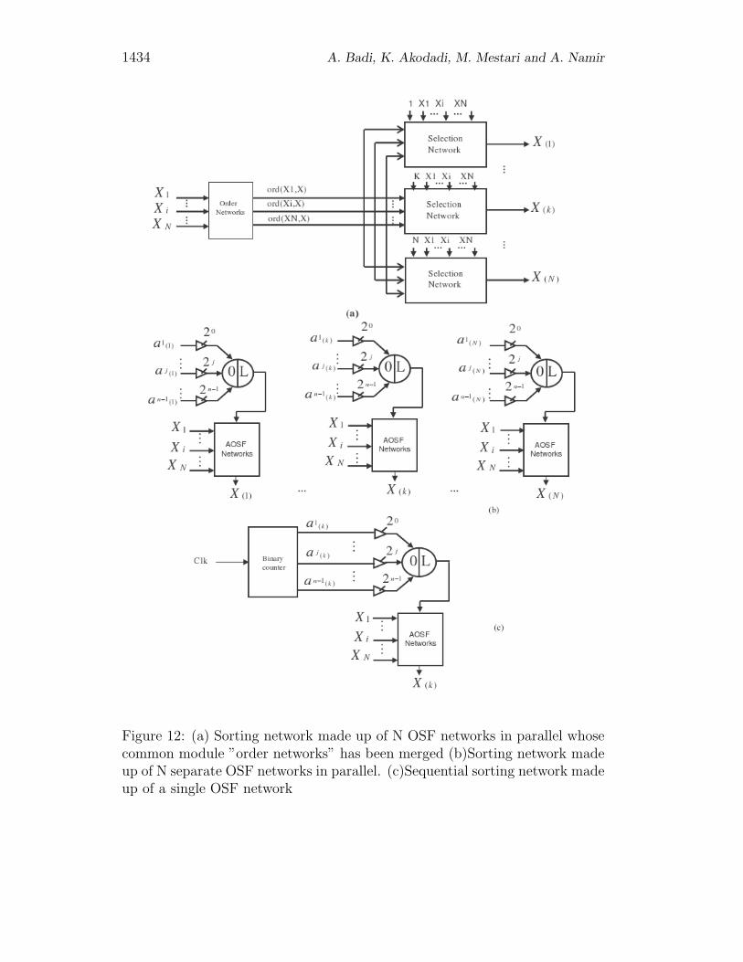
4.2 Simulation and MATLAB
Figure 13: Home Page For Simulation Simulink
1436 A. Badi, K. Akodadi, M. Mestari and A. Namir
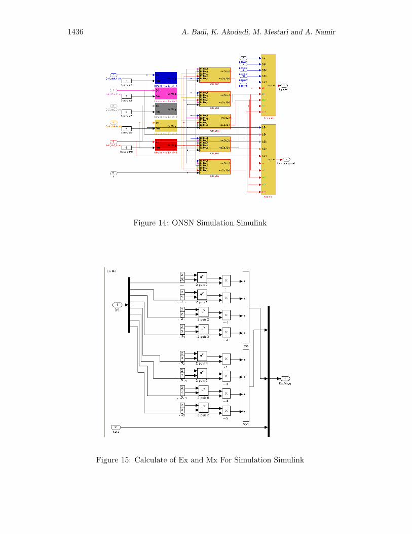
Figure 14: ONSN Simulation Simulink
Figure 15: Calculate of Ex and Mx For Simulation Simulink
Neural-network to solving output contention 1437
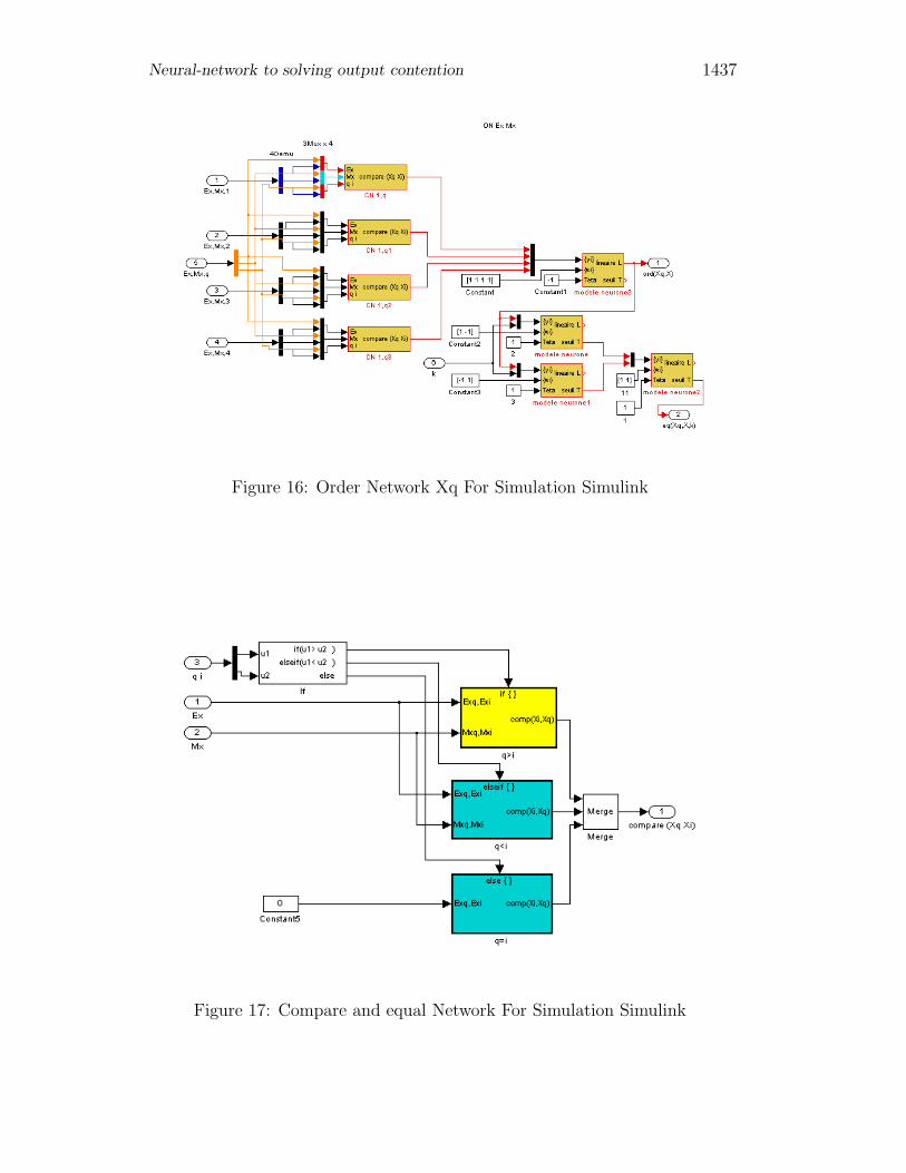
Figure 16: Order Network Xq For Simulation Simulink
Figure 17: Compare and equal Network For Simulation Simulink
1438 A. Badi, K. Akodadi, M. Mestari and A. Namir
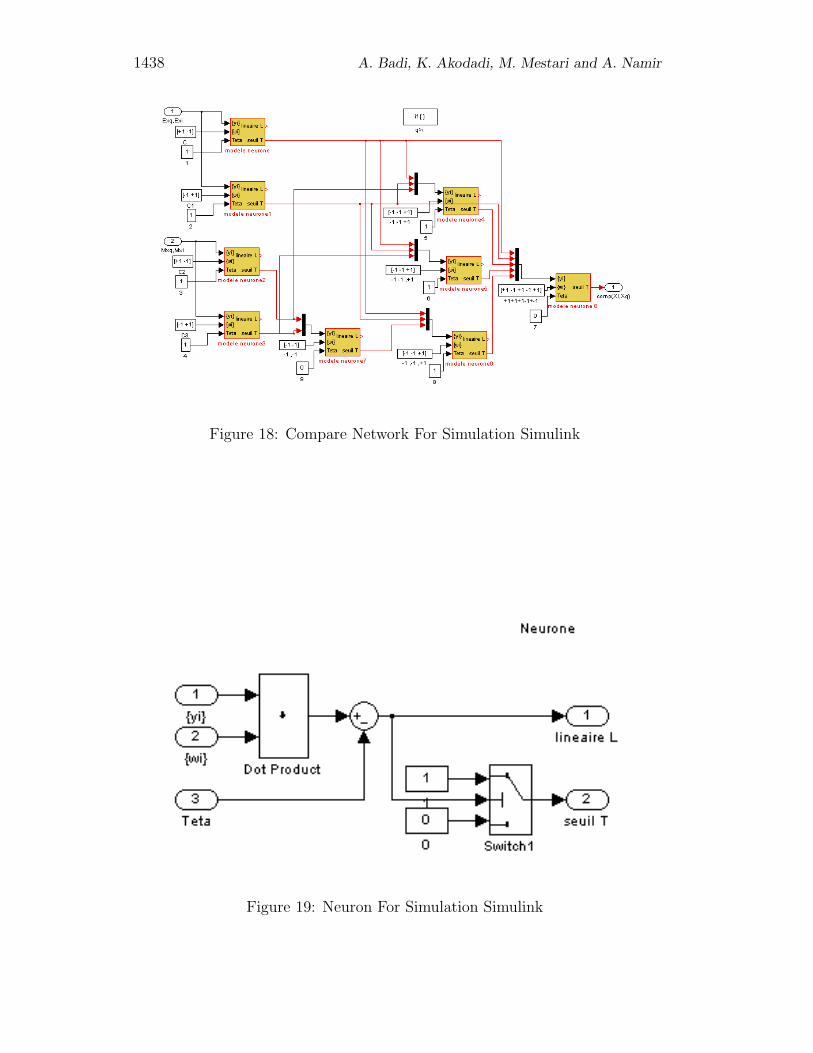
Figure 18: Compare Network For Simulation Simulink
Figure 19: Neuron For Simulation Simulink
Neural-network to solving output contention 1439
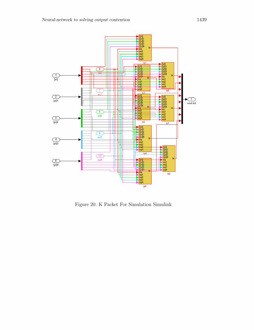
Figure 20: K Packet For Simulation Simulink
1440 A. Badi, K. Akodadi, M. Mestari and A. Namir
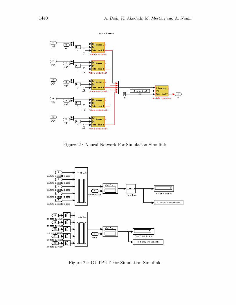
Figure 21: Neural Network For Simulation Simulink
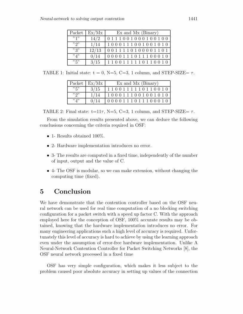
Figure 22: OUTPUT For Simulation Simulink
Neural-network to solving output contention 1441
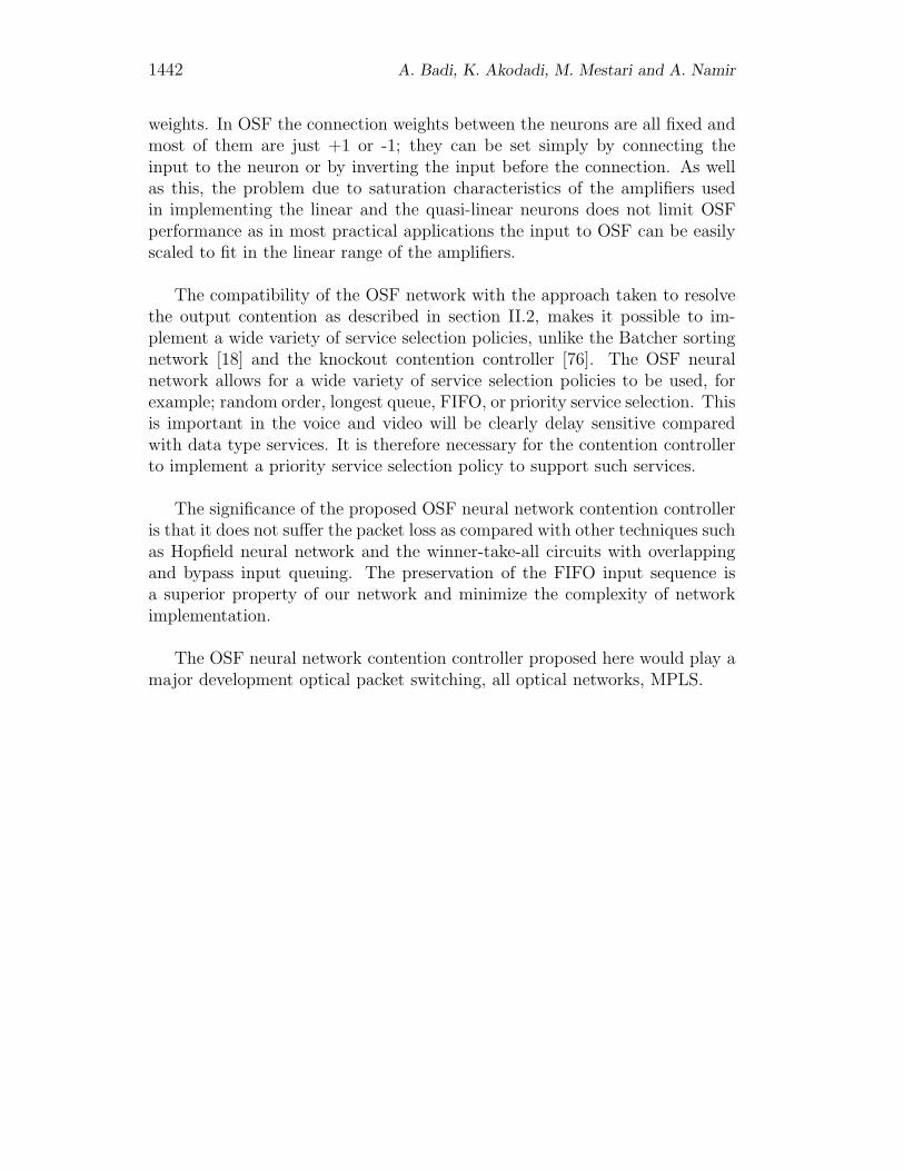
Packet Ex/Mx Ex and Mx (Binary)”1” 14/2 0 1 1 1 0 0 1 0 0 0 1 0 0 1 0 0”2” 1/14 1 0 0 0 1 1 1 0 0 1 0 0 1 0 1 0”3” 12/13 0 0 1 1 1 1 0 1 0 0 0 0 1 1 0 1”4” 0/14 0 0 0 0 1 1 1 0 1 1 1 0 0 0 1 0”5” 3/15 1 1 0 0 1 1 1 1 1 0 1 1 0 0 1 0
TABLE 1: Initial state: t = 0, N=5, C=3, 1 column, and STEP-SIZE= τ .
Packet Ex/Mx Ex and Mx (Binary)”5” 3/15 1 1 0 0 1 1 1 1 1 0 1 1 0 0 1 0”2” 1/14 1 0 0 0 1 1 1 0 0 1 0 0 1 0 1 0”4” 0/14 0 0 0 0 1 1 1 0 1 1 1 0 0 0 1 0
TABLE 2: Final state: t=11τ , N=5, C=3, 1 column, and STEP-SIZE= τ .
From the simulation results presented above, we can deduce the followingconclusions concerning the criteria required in OSF:
• 1- Results obtained 100%.
• 2- Hardware implementation introduces no error.
• 3- The results are computed in a fixed time, independently of the numberof input, output and the value of C.
• 4- The OSF is modular, so we can make extension, without changing thecomputing time (fixed).
5 Conclusion
We have demonstrate that the contention controller based on the OSF neu-ral network can be used for real time computation of a no blocking switchingconfiguration for a packet switch with a speed up factor C. With the approachemployed here for the conception of OSF, 100% accurate results may be ob-tained, knowing that the hardware implementation introduces no error. Formany engineering applications such a high level of accuracy is required. Unfor-tunately this level of accuracy is hard to achieve by using the learning approacheven under the assumption of error-free hardware implementation. Unlike ANeural-Network Contention Controller for Packet Switching Networks [8], theOSF neural network processed in a fixed time
OSF has very simple configuration, which makes it less subject to theproblem caused poor absolute accuracy in setting up values of the connection
1442 A. Badi, K. Akodadi, M. Mestari and A. Namir
weights. In OSF the connection weights between the neurons are all fixed andmost of them are just +1 or -1; they can be set simply by connecting theinput to the neuron or by inverting the input before the connection. As wellas this, the problem due to saturation characteristics of the amplifiers usedin implementing the linear and the quasi-linear neurons does not limit OSFperformance as in most practical applications the input to OSF can be easilyscaled to fit in the linear range of the amplifiers.
The compatibility of the OSF network with the approach taken to resolvethe output contention as described in section II.2, makes it possible to im-plement a wide variety of service selection policies, unlike the Batcher sortingnetwork [18] and the knockout contention controller [76]. The OSF neuralnetwork allows for a wide variety of service selection policies to be used, forexample; random order, longest queue, FIFO, or priority service selection. Thisis important in the voice and video will be clearly delay sensitive comparedwith data type services. It is therefore necessary for the contention controllerto implement a priority service selection policy to support such services.
The significance of the proposed OSF neural network contention controlleris that it does not suffer the packet loss as compared with other techniques suchas Hopfield neural network and the winner-take-all circuits with overlappingand bypass input queuing. The preservation of the FIFO input sequence isa superior property of our network and minimize the complexity of networkimplementation.
The OSF neural network contention controller proposed here would play amajor development optical packet switching, all optical networks, MPLS.
Neural-network to solving output contention 1443
References
[1] Y. S. Abu-Mostafa and D. Pslatis, ”Optical neural computers,” Sci.Amer., vol. 256, pp. 88-95, Mar. 1987.
[2] E. Ataman, V. K. Aatre, and K. M. Wong, ”A fast method for real-timemedian filtering, ” IEEE Trans. Acoust. Speech, Signal Processing, vol.ASSP-28, pp. 415-421, Aug. 1980.
[3] T. E. Bell, ”Optical computing: A field in flux, ” IEEE Spectrum, vol.23, pp. 34-57, Aug. 1986.
[4] Y. Ben-Asher, D. Peleg, R. Ramaswami, and A. Schuster, ”The power ofreconfiguration, ” J. Parallel Distrib. Comput., vol. 13, no. 2, pp. 139-153,1991.
[5] Y. Ben-Asher and A. Schuster, ”Optical splitting graphs,” presented atthe Int. Topical Meeting Optical Computing, Kobe, Japan, 1990.
[6] Bens, V. E., Mathematical Theory of connecting Networks and TelephoneTraffic. Academic Press, New York, 1965.
[7] L. Berger et. Al (2003, Jan). RFC 3471- Generalized multi-protocol labelswitching (GMPLS) signalling functional description. Internet Engineer-ing Task Force (IETF) proposed Standard.
[8] L. N. Binh and H. C. Chong, ”A neural network contention controllerfor packet switching networks,” IEEE Trans. Neural networks, vol. 6, pp.1402-1410, Nov. 1995.
[9] T. X. Brown, ”Neural networks for switching, ”IEEE Commun. Mag., vol.27, pp. 72-81, Nov. 1989.
[10] T. X. Brown and K. H. Liu, ”Neural network design of a Banyan networkcontroller,” IEEE J. Select. Areas Commun., vol. 8, pp. 1428-1473, 1990.
1444 A. Badi, K. Akodadi, M. Mestari and A. Namir
[11] T. X. Brown, ”Neural network design for switching network control.,” Ph.D. dissertation, California Inst. Technol., Pasadena, CA, 1990.
[12] T. X. Brown,”Neural networks for switching,” in Neural Networks inTelecommunications, B. Yuhas and N. Ansari, Eds. Boston, MA: Kluwer,1994.
[13] A. C. Bovic, T. S. Huang, and D. C. Munson, ”A generalization of me-dian filtering using linear combinations of order statistics, ”IEEE Trans.Acoust. Speech, Signal Processing, vol. ASSP-31, pp. 1342-1350, 1983.
[14] B. D. Calvert and C. A. Marinov, ”Another K-winner-take-all analogneural network,” IEEE Trans. Neural Networks, vol. 11, pp. 829-838, July2000.
[15] A. K. Chandra, L., Stockmeyer, and U. Vishkin, ”Constant depth re-ducibility,” SIAM J. Comput., vol. 13, pp. 423-439, 1984.
[16] A. Cichocki and R. Unbenhauen, ”Neural networks for solving systems oflinear equations and related problems,” IEEE Trans. Circuits Syst., vol.39, pp. 124-138, Feb. 1992.
[17] J. Choi and B. J. Shen, ”A high-precision VLSI winner-take-all circuit forself-organizing neural networks,” IEEE J. Solid-State Circuits, vol. 28, pp.576-583, May 1993.
[18] J. J. Degan, G. W. R. Luderer, and A. K. Vaidya, ”Fast packet technologyfor future switches, ” AT&T Tech. J., pp. 36-50, Mar./Apr. 1989.
[19] D. Del. Corso, K. E. Grosspietsh, and P. Treleveng, ”Silicon neural net-works,” Special Issue on a Collection of Good Papers on Digit and AnalogArtificial Neural Networks, IEEE Micro, vol. 9, Dec. 1989.
[20] H. Elgindy and P. Wegrowicz, ”Selection on the reconfigurable mesh,” inProc. Int. Conf. Parallel Processing, Aug. 1991, pp. III.26-III.33.
Neural-network to solving output contention 1445
[21] R. Erlansan and Y. Abu-Mustapha, ”Analog neural networks as de-coders,” in Advances in Neural Information Processing System, D. S.Touretzky, Ed. Los Altos, CA: Morgan Kaufmann, 1991, vol. 3, pp. 585-588.
[22] K. Fukushima, ”A neural network for visual pattern recognition,” IEEEComput, vol. 21, pp. 65-75, Mar. 1988.
[23] M. Furst, J. B. Saxe, and M. Sipser, ”Parity, circuits and the polynomial-time hierarchy,” in Proc. 22nd IEEE Symp. Foundations Computer Sci-ence, 1981, pp. 260-270.
[24] E. Hao, P. D. MacKenzie, and Q. F. Stout, ”Selection on the reconfig-urable mesh,” in Proc. Frontiers Massively Parallel Computation, Oct.1992, pp. 38-45.
[25] J. J. Hopfield and D. W. Tank, ”Simple ’Neural’ optimization networks anA/D converter, signal decision circuit, and a linear programming circuit,”IEEE Trans. Circuits Syst. Vol. CAS-33, pp. 533-541, May 1986.
[26] T. S. Huang, G. J. Yang, and G. Y. Tang, ”A fast two-dimensional medianfiltering algorithm,” IEEE Trans. Acoust. Speech, Signal Processing, vol.ASSP-27, pp. 13-18, Feb. 1979.
[27] Inose, H., An Introduction to Digital Integrated Communications Sys-tems, Univ. Tokyo Press, 1979.
[28] J. Jang and V. K. Prasana, ”An optimal sorting algorithm on reconfig-urable mesh,” J. Parallel and Distributed Computing, vol. 25, pp. 31-41.Feb. 1995.
[29] L. G. Johnson and S. M. S. Jalaleddine, ”MOS implementation of switch-take-all network with application to content-addressable memory.” Lett,vol. 27, no. pp. 957-958, May 1991.
1446 A. Badi, K. Akodadi, M. Mestari and A. Namir
[30] S. Y. Kim, S. H. Lee, S. S. Lee and J. S. Lee, ”Upgading WDM networksusing ultradense WDM channel group,” Photonics Technology Letters,IEEE, vol. 16 no.8, pp. 1966-1968, Aug., 2004.
[31] T. Kohonen, ”Correlation matrix memories,” IEEE Trans. Comput., vol.C-12, pp. 353-359, 1972.
[32] J. Lazaro, S. Ryckebush, M. A. Mahowald, and C. A. Mead, ”Winner-take-all networks of O(N) complexity,” in Advances in Neural InformationProcessing System, D. S. Touretzky, Ed. Los Altos, CA: Morgan Kauf-mann, 1989, vol. pp. 703-711.
[33] Y. H. Lee and A. T. Fam, ”An edge gradient enhancing adaptive or-der statistic filter,” IEEE Trans. Acoust. Speech, Signal Processing, vol.ASSP-35, pp. 680-695, 1987.
[34] J. Levinson, I. Kuroda, and T. Nishitani, ”A reconfigurable processorarray with routing LSI’s and general purpose DSP’s,”in Proc. Int. Conf.Application Specific Array Processor, Oct. 1992.
[35] H. Li and M. Maresca, ”Polymorphic-torus network,” IEEE Trans. Com-put., vol. 38, pp. 1345-1351, Sept. 1989.
[36] R. Lin, S. Olariu, J. Schwing, and J. Zhang, ”A VLSI-optimal constanttime sorting on reconfigurable mesh,” in Proc. 9th Eur. Workshop parallelComputing, Spain, 1992, pp. 1-16.
[37] R. P. Lippman, ”An introduction to computing with neural nets,” IEEETrans. Acoust., Speech, Signal Processing, vol. 35, pp. 244, Apr. 1987.
[38] A. Marrakchi and T. Troudet, ”A neural net arbitrator for large crossbarpacket switches,” IEEE Trans. Circuits Syst., vol. 36, no. 7, p. 1039-1041,July 1989.
[39] C. Mead and M. Ismail, Analog VLSI and Neural Systems. Reading, MA:Addison-Wesley, 1989.
Neural-network to solving output contention 1447
[40] C. Mead and M. Ismail, Analog VLSI Implementation of Neural Systems.Norwell, MA: Kluwer, 1989.
[41] M. Mestari and A.NAmir, ”AMAXNET: A neural network implementa-tion of adjustable MAXNET in fixed time,” in Proc. IFAC-IFIP-IMACSInt. Conf. Control Industriel System, vol. 2, Belfort, France, May 20-22,1997, pp. 543-549.
[42] M. Mestari and A.Namir, ”MinMaxNet: A neural network implementa-tion of min/max filters, ”in IFIP Proc. Int. Conf. Optimization-BasedComputer-Aided Modeling Design, vol. 1, Noisy-le-Grand, Paris, France,May 28-30, 1996, pp. 26.1-26.4.
[43] M. Mestari and A. Namir, ”AOSNET: A neural network implementationof adjustable order statistic filters in fixed time, ”SIAMS J., vol. 36, pp.509535, 2000.
[44] M. Mestari and A. Namir, ”A neural network implementation of L∞,metric partitional clustering in fixed time, ”SIAMS J., vol. 41, no. 2, pp.351-380, 2001.
[45] M. Mestari, A. Namir and J. Abouir, ”Switched capacitor neural networksfor optimal control of nonlinear dynamic systems: Design and stabilityanalysis, ”SIAMS J. vol. 41, no. 3, pp. 559-591, 2001.
[46] M. Mestari, ”A Analog Neural Network Implementation in Fixed Time ofAdjustable Order Statistic Filters and Applications”, IEEE Transactionson Neural networks, vol. 15, no. 3, May 2004, pp. 766-785.
[47] M. Mestari, M. Benzirar, M. Elhammouti, A. Yeznasni, and J. Meziane” Calculation of the diffusion coefficient in a heated turbulant mediumusing optimisation technique”, International Journal of Engineering Sci-ence, vol. 40, pp. 2001-2021, 2002.
[48] M. Mestari, M. Benzirar, M. Elhammouti, A. Yaznasni, and J. Meziane”Measurement of inverse temperature gradient along a turbulent planeflame using an optical method”, communications in Nonlinear Science
1448 A. Badi, K. Akodadi, M. Mestari and A. Namir
and Numeric Simulation Journal, vol. 9, pp. 367-377, 2004.
[49] M. Mestari and A. Namir, ”Optimal control of discrete nonlinear dynamicsystem using decomposition coordination method II”, IFIP Proc. Conf. onOptimization-Based Computer-Aided Modelling and Design, 28-30 May,Noisy-le-grand, Paris, (France), vol. 1, pp. 25.1-25.4, 1996.
[50] M. Mestari and A. Namir, ”Optimisation control of discrete nonlinear dy-namic system using decomposition coordination method I”, AMSE Proc.Internat. Conf. on Communication, Signal and Systems, vol. 2, pp. 873-882, 1996.
[51] M. Mestari, K. Akodadi and A. Badi, ”Neural networks for solving non-linear constrained multi-objective optimization problems”, IEEE-URST-CST Proc. Internat. Sympasium TELECOM’2005, March 23-25 Rabat(Morocco), pp. 687-690, 2005.
[52] M. Mestari, K. Akodadi and A. Badi, ”Neural networks classifier”, IEEE-URST-CST Proc. Internat. Sympasium TELECOM’2005, March 23-25Rabat (Morocco), pp. 687-690, 2005.
[53] M. Mestari, A. Namir, K. Akodadi, and A. Badi ”O(1) Time neural net-work distance classifier”, MCSEAI’06, Dec 07-09 Agadir (Morocco), 2006.
[54] R. Miler, V. K. Prasana Kumar, D. I. Reisis, and Q. F. Stout, ”Mesheswith reconfigurable buses,” in Proc. MIT Conf. Advanced Research VLSI,Apr. 1988, pp. 163-178.
[55] Y. Nakagawa and A. Rosenfeld, ”A note of the use of local min andmax operations in digital picture processing, ”IEEE Trans. Syst., Man,Cybern, vol. SMC-8, pp. 632-635, 1978.
[56] K. Nakano, T. Msuzawa, and N. Tokura, ”sub-logarithmic time sortingalgorithm on a reconfigurable artay,” IEICE, vol.E-74, No.11.pp.3894-3901,Nov.1991.
Neural-network to solving output contention 1449
[57] P. M. Narendra, ”A seperable median filter for image noise smoothing,”IEEE Trans. Pattern Anal. Machine Intell., vol. PAMI-3, pp. 20-29, JAN.1981. configurable artay, ”IEICE, vol. E-74, no. 11, pp. 3894-3901, Nov.1991.
[58] K. Nichols et al. (2001, apr). RFC 3068- definition of differentiated ser-vices per domain behaviours and rules for their specification. InternetEngineering Task Force (IEFTF) Proposed Standard.
[59] M. Nigam and S. Sahni, ”sorting n numbers on nxn reconfigurable mesheswith buses, ”in Proc. Int. Parallel Processing Symp., Apr. 1993, pp. 174-181.
[60] J. Pankove, C. Radehaus, and K. Wanger, ”Winner-take-all neural netwith memory, ”Electron. Lent, vol. 26, no. 6, pp. 349-350, Mar. 1990.
[61] V. K. Prasana Kumar and C. S. Ragavenda, ”Array processor with multi-ple broadcasting,” J. Parallel Distrib. Comput. Vol. 4, pp. 173-190, 1987.
[62] Pattavina, A, ”Architectures and performance of optical packet switchingnodes for IP networks,” Journal of lightwave technology, vol. 23, pp. 1023-1032, (3), March, 2005.
[63] D. S. Richrad, ”VLSI median filters,” IEEE Trans. Acoust. Speech, SignalProcessing, vol, 38, pp. 145-153, Jan. 1990.
[64] J. Rothsten, ”Bus automata, brains, and mental model,” IEEE Trans.Syst., Man, Cybern., vol. 18, pp. 522-531, Apr. 1988.
[65] Schwartz, Telecommunication Networks: Protocols, Modelling, and Anal-ysis, Addison-Wesley Pub. Co., Reading, MA., 1979.
[66] G. Seiler and J. A. Nossek, ”Winner-take-all cellular neural networks,”IEEE Trans. Circuits Syst. II, vol. 40, pp. 184-194, Mar. 1993.
1450 A. Badi, K. Akodadi, M. Mestari and A. Namir
[67] P. Shi and R. K. Ward, ”A neural network implementation of medianfiltering,” in IEEE Pacific Rim Conf., Victoria, BC, Canada, 1989.
[68] Shun Yao, S.J B, Mukherjee B, Dixit S.” All optical packet switching formetropolitan area networks: opportunities and challenges” Communica-tions Magazine IEEE, vol.39, no, pp. 142-148, March 2001.
[69] L. Snyder, ”Introduction to the reconfigurable highly parallel computer,”Comput., vol. 15, no. 1, pp. 47-56, Jan. 1982.
[70] B. W. Suter and M. Kabrisky, ”On a magnitude preserving iterativeMaxnet algorithm,” neural Comput., vol. 4, pp. 224-233, 1992.
[71] T. P. Troudet and S. M. Walters, ”Neural network architecture for cross-bar switch control,” IEEE Trans. Circuits Syst., vol 38, no. 1, pp. 42-56,Jan. 1991.
[72] K. Urahama and T. Nagao, ”K-winners-take-all circuit with O(N) com-plexity,” IEEE Trans. Neural Networks, vol. 6, PP. 776-778, May 1995.
[73] B. F. Wang, G. H. Chen, and F. C. Lin, ”Constant time sorting onaprocessor array with a reconfigurable bus systems, ”Inform. ProcesingLett., pp. 187-192, 1990.
[74] J. H. Winters and C. Rose, ”Minimum distance automata in parallel net-works for optimum classification,” Neural Networks, vol. 2, pp. 127-132,1989.
[75] W. J. Wolfe, D. mathis, C. Anderson, J. Rothman, M. Gottler, G. Brady,R. Walker, G. Duane, and G. Alaghband, ”K-winer networks,” IEEEtrans. Neural Networks, vol. 2, no. 2, pp. 310-315, Mar. 1991.
[76] Y. S. Yeh, M. G. Hluchyj, and A. S. Acompora, ”The knockout switch,”IEEE J. Select. Areas Commun., vol. SAC-5, no. 8, pp. 1274-1283, Oct.1987.
Neural-network to solving output contention 1451
[77] S. Zunino, ”Circuit implementation of the K-winer machine,” Electron.Lett., vol. 35, no. 14, pp. 1172-1173, July 8, 1999.
Received: November, 2008