Embed Size (px)
Citation preview
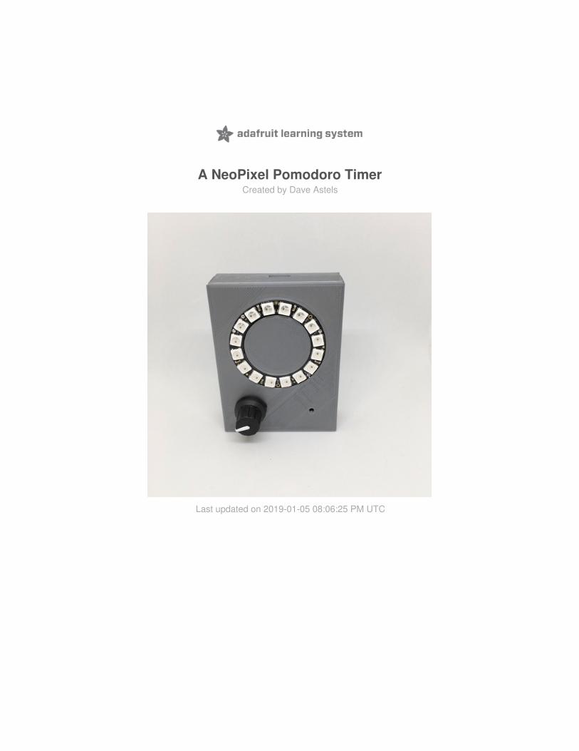
A NeoPixel Pomodoro TimerCreated by Dave Astels
Last updated on 2019-01-05 08:06:25 PM UTC

23455
666
67
77
78
88
81017
Guide Contents
Guide ContentsOverview
PartsMaterials and SuppliesTools
HardwareWhich CircuitPython Board?
Adafruit ItsyBitsy M0 Express - for CircuitPython & Arduino IDE
How To Make Noise?Piezo Buzzer
How To Show Time Progressing?NeoPixel Ring - 16 x 5050 RGB LED with Integrated Drivers
How To Set Time?Rotary Encoder + Extras
Making It PortableAdafruit LiIon/LiPoly Backpack Add-On for Pro Trinket/ItsyBitsy
Final Wiring DiagramCodeAssembly
© Adafruit Industries https://learn.adafruit.com/a-neopixel-pomodoro-timer Page 2 of 32

Overview
I know many people who get value from a simple tool called the Pomodoro Technique.
It's a time management technique used to break work into periods of activity separated by short breaks. Each activityperiod is called a pomodoro. Why "pomodoro"? The technique was developed by Francesco Cirillo, who named thetechnique "pomodoro" as a nod to the tomato kitchen timer he initially used.
The technique has come a long way from those humble beginnings with phone apps, web versions, etc. I decided tomake a simple hardware version in CircuitPython with a rotary encoder to set the time and mode!
© Adafruit Industries https://learn.adafruit.com/a-neopixel-pomodoro-timer Page 3 of 32

Parts
Here's what you'll need from Adafruit to build the Pomodoro Timer:
1 x Adafruit ItsyBitsy M0 Express - for CircuitPython and Arduino IDEWhat's smaller than a Feather but larger than a Trinket? It's an Adafruit ItsyBitsy M0 Express!
ADD TO CART
1 x NeoPixel Ring - 16 x 5050 RGB LED with Integrated DriversRound and round and round they go! 16 ultra bright smart LED NeoPixels are arranged in a
circle with 1.75" (44.5mm) outer diameter.
ADD TO CART
1 x Piezo BuzzerPiezo buzzers are used for making beeps, tones and alerts. This one is petite but loud!
ADD TO CART
1 x Rotary Encoder + ExtrasThis rotary encoder is the best of the best, its a high quality 24-pulse encoder, with detents and
a nice feel.
ADD TO CART
1 x LiIon/LiPoly BackpackAdafruit LiIon/LiPoly Backpack Add-On for Pro Trinket/ItsyBitsy
ADD TO CART
1 x Breadboard-friendly SPDT Slide SwitchThese nice switches are perfect for use with breadboard and perfboard projects.
ADD TO CART
© Adafruit Industries https://learn.adafruit.com/a-neopixel-pomodoro-timer Page 4 of 32

1 x Lithium Ion Polymer Battery - 3.7v 500mAhLithium ion polymer (also known as 'lipo' or 'lipoly') batteries are thin, light and powerful. This
battery has a capacity of 500mAh for a total of about 1.9 Wh.
ADD TO CART
1 x Silicone Cover Stranded-Core Wire - 50ft 30AWG BlueSilicone-sheathing wire is super-flexible and soft, and its also strong! Available in various
colors.
ADD TO CART
Materials and Supplies
3D Printer and FilamentSuperglueSmall diameter heatshrink tubing
Tools
Wire StrippersWire CuttersPliersPin-vise drill and 0.8mm drill bitSoldering IronSolder
© Adafruit Industries https://learn.adafruit.com/a-neopixel-pomodoro-timer Page 5 of 32

Hardware
My goal was to make a pomodoro timer using a few basic parts and write the code for it using CircuitPython.
My requirements were pretty simple:
1. write the code in CircuitPython,2. have an audible alert to indicate transition between the work/break phases,3. have a display of some sort to show progress through each phase, and4. have a way to set the length of each phase.
Which CircuitPython Board?
To satisfy requirement 1, I needed to use an Adafruit M0 or M4 microcontroller based board. I decided to see if I couldmake it work with an M0. These boards are great for simple CircuitPython projects, but if you have much code it's easyto run into memory limitations.
For very simple projects, a Trinket M0 does a great job, but I eventually decided to use a rotary encoder and wantedto try out the new rotaryio support in the latest 3.0 release of CircuitPython. That ruled the Trinket out.
So that left the M0 Express versions of the Feather or ItsyBitsy. Either would work, but I decided to use the ItsyBitsy:it's smaller, so it would give me a bit more flexibility when it came time to designing a case. It would provide a bit moreof a challenge, as well, due to the lack of mounting holes that the Feather has.
How To Make Noise?
For requirement 2, I used the same piezo buzzer I used in my Humidity monitor guide (https://adafru.it/BIS). It's loudenough, small, and works nicely with the CircuitPython pulseio library.
Your browser does not support the video tag. Adafruit ItsyBitsy M0 Express - for CircuitPython & ArduinoIDE
$11.95IN STOCK
ADD TO CART
© Adafruit Industries https://learn.adafruit.com/a-neopixel-pomodoro-timer Page 6 of 32

How To Show Time Progressing?
When I thought about requirement 3, I thought about my toaster's interface. It uses a continuous knob and a radialdisplay for setting darkness.
What isn't obvious from the photo is that the highest valued segment of the dial blinks as it counts down. Also, as thecount down proceeds, the number of segments lit decreases. When none remain lit, the toast is done.
This immediately reminded me of a Light Emitting Diode (LED) NeoPixel ring.
How To Set Time?
Piezo Buzzer
$1.50IN STOCK
ADD TO CART
NeoPixel Ring - 16 x 5050 RGB LED with Integrated Drivers
$9.95IN STOCK
ADD TO CART
© Adafruit Industries https://learn.adafruit.com/a-neopixel-pomodoro-timer Page 7 of 32

For the final requirement I was still thinking about my toaster and a rotary encoder as input made sense, especiallysince I'd decided to use a ring as a display.
Rotating the encoder could be used to set the times, while the push switch could be used to cycle through modes:
timer -> set work time -> set break time -> timer
and so on.
I'd implemented rotary encoder handling in CircuitPython in a previous guide (https://adafru.it/BIT), but this was a goodchance to try out the new bundled rotary encoder support.
Making It Portable
All that was left was adding a LiPo backpack so that it could be battery powered. The backpack is required since theItsyBitsy doesn't have on-board battery support. That's one of the tradeoffs compared to the Feather. The nice thingabout the backpack is that it doesn't increase the footprint, but it does add to the thickness of the ItsyBitsy. Thatwouldn't be a problem since the case will have plenty of thickness to accommodate it.
Final Wiring Diagram
That's it: an ItsyBitsy M0 Express with a NeoPixel ring, a rotary encoder, and a piezo buzzer. Add in a LiPo backpack,power switch, and battery for power, and that's it. Below is the wiring diagram. The only difference is that I'm using a500mAh LiPo in my build. Making the case bigger will allow use of a bigger battery. That makes no difference to thewiring, though.
Rotary Encoder + Extras
$4.50IN STOCK
ADD TO CART
Adafruit LiIon/LiPoly Backpack Add-On for ProTrinket/ItsyBitsy
$4.95IN STOCK
ADD TO CART
© Adafruit Industries https://learn.adafruit.com/a-neopixel-pomodoro-timer Page 8 of 32

Wiring is pretty straight-forward and described in detail on the Assembly page.
The battery connects to the LiPo backpack. The slide switch does as well, allowing the device to be turned off whennot in use. The backpack is connected to the power connections on the ItsyBitsy, typically (as I did) by using theincluded bit of long-pin header.
The buzzer connects to ground and D12.
The Neopixel ring has it's power connected to the ItsyBitsy's 3v output, and it's ground to the ItsyBitsy's. The ring hastwo ground connections, and the second can be used during construction to avoid having to connect everythingdirectly to the ItsyBitsy's ground. The ring's Data In connects to D11.
The center of the encoder, and one side of its switch connects to ground. The other side of its switch connects to D10,while its encoder pins connect to D9 and D7. Done as shown, the code will work correctly with the rotation direction. Ifyou reverse the encoder connections, rotation will be opposite what's expected. Reverse the connections or switch theencoder pins in the code to correct it.
© Adafruit Industries https://learn.adafruit.com/a-neopixel-pomodoro-timer Page 9 of 32

Code
As with most of my projects these days, I used CircuitPython for this. Are you new to using CircuitPython? No worries,there is a full getting started guide here (https://adafru.it/cpy-welcome).
Adafruit suggests using the Mu editor to edit your code and have an interactive REPL in CircuitPython. You can learnabout Mu and installation in this tutorial (https://adafru.it/ANO).
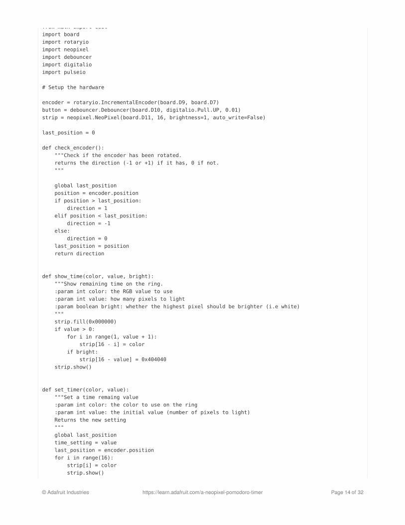
We'll go through the code, piece by piece, starting with the imports and setup.
Here the rotary encoder is set up using the new built-in support for the rotation of the switch and I use my debouncerlibrary to clean up the encoder push switch. Finally the NeoPixel strip is configured. If you are unfamiliar withNeoPixels, there is a great guide on them (https://adafru.it/dhw).
Now let's jump to the main loop:
import timefrom math import ceilimport boardimport rotaryioimport neopixelfrom adafruit_debouncer import Debouncerimport digitalioimport pulseio
# Setup the hardware
encoder = rotaryio.IncrementalEncoder(board.D9, board.D7)button_io = digitalio.DigitalInOut(board.D10)button_io.direction = digitalio.Direction.INPUTbutton_io.pull = digitalio.Pull.UPbutton = Debouncer(button_io)strip = neopixel.NeoPixel(board.D11, 16, brightness=1, auto_write=False)
© Adafruit Industries https://learn.adafruit.com/a-neopixel-pomodoro-timer Page 10 of 32

Each time through the loop, it checks for a push on the encoder switch. That's the job of the debouncer's updatefunction. If one was detected (i.e. the button signal went from high to low... it fell) the code enters the mode to set thelength of the work phase, followed by the break phase, then back to timing mode.
The next step checks to see if it's time to update the timer. It does this every second (as defined by the last line). Soonce a second, the time remaining is decreased by 1 (second) and the ring is updated. If it reaches 0, it's time to makesome noise and change mode.
In addition to the setup and loop there are a handful of helper functions.
The check_encoder function tracks the position of the encoder, comparing it to the last known position. Based on that
strip.fill(0x000000)strip.show()work_time = 6break_time = 2time_to_check = 0state = Falsemode, dial_color, time_remaining, increment = compute_mode_settings(True)
while True: # check whether the rotary encoder has been pushed. If so enter time-set mode. button.update() if button.fell: work_time = set_timer(0x400000, work_time) break_time = set_timer(0x004000, break_time) strip.fill(0x000000) strip.show() mode, dial_color, time_remaining, increment = compute_mode_settings(True)
now = time.monotonic() if now >= time_to_check: #only check each second time_remaining -= 1 if time_remaining <= 0: # time to switch modes? strip.fill(0x000000) # clear the dial strip.show() # make some noise beep(2, 0.5, 0.25, 4000) mode, dial_color, time_remaining, increment = compute_mode_settings(not mode) state = not state # have the top pixel toggle between the dial color and white show_time(dial_color, ceil(time_remaining / increment), state) #update the dial time_to_check = now + 1.0
last_position = 0
def check_encoder(): global last_position position = encoder.position if position > last_position: direction = 1 elif position < last_position: direction = -1 else: direction = 0 last_position = position return direction
© Adafruit Industries https://learn.adafruit.com/a-neopixel-pomodoro-timer Page 11 of 32

comparison it returns -1, 0, or 1 to indicate that the encoder rotated counter-clockwise, didn't move, or rotatedclockwise.
The show_time function updates the time displayed on the NeoPixel ring. It sets pixels to the specified color starting atpixel zero (which is at the bottom of the ring in the final build) and moving clockwise. The final pixel is handleddifferently. Depending on the bright parameter, it's either set to the same color as the rest, or white. In the main loopwe saw that this value gets toggled each second. The result is that the highest pixel blinks.
Note that for the work and break times, each pixel is worth a different number of seconds. This is because it's typicalfor the work phase to be a half hour, an hour, or longer, while the break phase is usually between five and fifteenminutes. To give a better, brighter display, I decided to use a different scale for each. This is all adjustable in thecompute_mode_settings function:
Depending on which mode is being entered, the appropriate set of values is returned. These are used to update thevariables in the loop (see above).
When there's a switch from one phase to the next, we use the piezo buzzer and pulseio to make some noise. Thebeep function does that:
This is straightforward. It sets up the pulse-width modulation (PWM), loops for the number of beeps requested, andshuts down the PWM. For each beep it sets the duty cycle to 50%, waits for the beep duration, sets the duty cycle to0% (effectively turning of the sound), then waits for the interstitial duration before playing the next beep (if any).
Next is maybe the most interesting function.
def show_time(color, value, bright): strip.fill(0x000000) if value > 0: for i in range(1, value + 1): strip[16 - i] = color if bright: strip[16 - value] = 0x404040 strip.show()
def compute_mode_settings(new_mode): work_time_increment = 600 # each work phase pixel is worth 10 minutes break_time_increment = 300 # each break phase pixel is worth 5 minutes
if new_mode: return True, 0x400000, work_time * work_time_increment, work_time_increment else: return False, 0x004000, break_time * break_time_increment, break_time_increment
def beep(count, duration, interstitial, freq): pwm = pulseio.PWMOut(board.D12, duty_cycle = 0, frequency=freq) for _ in range(count): pwm.duty_cycle = 0x7FFF time.sleep(duration) pwm.duty_cycle = 0 time.sleep(interstitial) pwm.deinit()
© Adafruit Industries https://learn.adafruit.com/a-neopixel-pomodoro-timer Page 12 of 32

To start, it initializes from the current encoder position and flashes the ring. Following that there's a loop that showsthe current setting (using the show_time function we looked at above) and checks the encoder push switch. If it waspressed the current setting is returned. Otherwise the encoder's rotation is checked and the time setting changedbased on the result. Finally the time setting is capped at 0 and 16, which reflects the size of the ring.
That's it. Each piece is fairly simple, but the overall functionality is interesting and useful. Below is all of it, withcomments.
def set_timer(color, value): global last_position time_setting = value last_position = encoder.position for i in range(16): strip[i] = color strip.show() for i in range(16): strip[i] = 0x000000 strip.show() while True: show_time(color, time_setting, False) button.update() if button.fell: return time_setting direction = check_encoder() time_setting += direction if time_setting > 16: time_setting = 16 if time_setting < 0: time_setting = 0
"""The MIT License (MIT)
Copyright (c) 2018 Dave Astels
Permission is hereby granted, free of charge, to any person obtaining a copyof this software and associated documentation files (the "Software"), to dealin the Software without restriction, including without limitation the rightsto use, copy, modify, merge, publish, distribute, sublicense, and/or sellcopies of the Software, and to permit persons to whom the Software isfurnished to do so, subject to the following conditions:
The above copyright notice and this permission notice shall be included inall copies or substantial portions of the Software.
THE SOFTWARE IS PROVIDED "AS IS", WITHOUT WARRANTY OF ANY KIND, EXPRESS ORIMPLIED, INCLUDING BUT NOT LIMITED TO THE WARRANTIES OF MERCHANTABILITY,FITNESS FOR A PARTICULAR PURPOSE AND NONINFRINGEMENT. IN NO EVENT SHALL THEAUTHORS OR COPYRIGHT HOLDERS BE LIABLE FOR ANY CLAIM, DAMAGES OR OTHERLIABILITY, WHETHER IN AN ACTION OF CONTRACT, TORT OR OTHERWISE, ARISING FROM,OUT OF OR IN CONNECTION WITH THE SOFTWARE OR THE USE OR OTHER DEALINGS INTHE SOFTWARE."""# pylint: disable=global-statement
import timefrom math import ceil
© Adafruit Industries https://learn.adafruit.com/a-neopixel-pomodoro-timer Page 13 of 32
from math import ceilimport boardimport rotaryioimport neopixelimport debouncerimport digitalioimport pulseio
# Setup the hardware
encoder = rotaryio.IncrementalEncoder(board.D9, board.D7)button = debouncer.Debouncer(board.D10, digitalio.Pull.UP, 0.01)strip = neopixel.NeoPixel(board.D11, 16, brightness=1, auto_write=False)
last_position = 0
def check_encoder(): """Check if the encoder has been rotated. returns the direction (-1 or +1) if it has, 0 if not. """
global last_position position = encoder.position if position > last_position: direction = 1 elif position < last_position: direction = -1 else: direction = 0 last_position = position return direction
def show_time(color, value, bright): """Show remaining time on the ring. :param int color: the RGB value to use :param int value: how many pixels to light :param boolean bright: whether the highest pixel should be brighter (i.e white) """ strip.fill(0x000000) if value > 0: for i in range(1, value + 1): strip[16 - i] = color if bright: strip[16 - value] = 0x404040 strip.show()
def set_timer(color, value): """Set a time remaing value :param int color: the color to use on the ring :param int value: the initial value (number of pixels to light) Returns the new setting """ global last_position time_setting = value last_position = encoder.position for i in range(16): strip[i] = color strip.show() for i in range(16):
© Adafruit Industries https://learn.adafruit.com/a-neopixel-pomodoro-timer Page 14 of 32

for i in range(16): strip[i] = 0x000000 strip.show() while True: show_time(color, time_setting, False) button.update() if button.fell: return time_setting direction = check_encoder() time_setting += direction if time_setting > 16: time_setting = 16 if time_setting < 0: time_setting = 0
def beep(count, duration, interstitial, freq): """Make some noise :param int count: the number of beeps to make :param float duration: the length (in seconds) of each beep :param float interstitial: the length (in seconds) of the silence between beeps :param int freq: the frequency of the beeps """ pwm = pulseio.PWMOut(board.D12, duty_cycle = 0, frequency=freq) for _ in range(count): pwm.duty_cycle = 0x7FFF time.sleep(duration) pwm.duty_cycle = 0 time.sleep(interstitial) pwm.deinit()
def compute_mode_settings(new_mode): """Compute settings for a new mode :param boolean new_mode: the new mode Returns boolean mode - the new mode int dial_color - the dial color for the new mode int time_remaining - the initial time-remaining for the new mode int increment - the pixel increment for the new mode """ work_time_increment = 600 break_time_increment = 300
if new_mode: return True, 0x400000, work_time * work_time_increment, work_time_increment else: return False, 0x004000, break_time * break_time_increment, break_time_increment
# Initialize things
strip.fill(0x000000)strip.show()work_time = 6break_time = 2time_to_check = 0state = Falsemode, dial_color, time_remaining, increment = compute_mode_settings(True)
© Adafruit Industries https://learn.adafruit.com/a-neopixel-pomodoro-timer Page 15 of 32

# The main loop
while True: # check whether the rotary encoder has been pushed. If so enter time-set mode. button.update() if button.fell: work_time = set_timer(0x400000, work_time) break_time = set_timer(0x004000, break_time) strip.fill(0x000000) strip.show() mode, dial_color, time_remaining, increment = compute_mode_settings(True)
now = time.monotonic() if now >= time_to_check: #only check each second time_remaining -= 1 if time_remaining <= 0: # time to switch modes? strip.fill(0x000000) # clear the dial strip.show() # make some noise beep(2, 0.5, 0.25, 4000) mode, dial_color, time_remaining, increment = compute_mode_settings(not mode) state = not state # have the top pixel toggle between the dial color and white show_time(dial_color, ceil(time_remaining / increment), state) #update the dial time_to_check = now + 1.0
© Adafruit Industries https://learn.adafruit.com/a-neopixel-pomodoro-timer Page 16 of 32

Assembly
The picture below shows all the parts, ready for assembly. The STL files for printing the case are at the bottom of thispage.
We'll start by mounting the LiPo backpack on the ItsyBitsy using the long header pins provided. Remember to trim theheader pins afterward.
© Adafruit Industries https://learn.adafruit.com/a-neopixel-pomodoro-timer Page 17 of 32

In order to use the switch for power, the trace between the switch pads must be cut. That's shown here.
© Adafruit Industries https://learn.adafruit.com/a-neopixel-pomodoro-timer Page 18 of 32

The next step is to add wires for the NeoPixels, buzzer, and rotary encoder. I used yellow for these. Be sure to makethem plenty long, you can always trim them later. 120cm (4-5 inches) is fine.
© Adafruit Industries https://learn.adafruit.com/a-neopixel-pomodoro-timer Page 19 of 32

Next add two wires for the power switch. I used green for these. Again, 120cm or so (4-5 inches) is plenty.
© Adafruit Industries https://learn.adafruit.com/a-neopixel-pomodoro-timer Page 20 of 32

The last step for the ItsyBitsy is ground and power. The ground hole is being used by the LiPo backpack, so you willneed to solder the ground wire onto the end on the pin on the backpack.
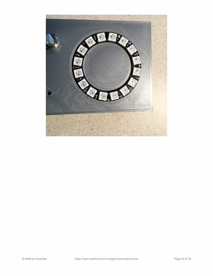
The next step requires a fine drill bit. I have a small jewelers drill that's idea for this, and a drill bit that fits a through-hole PCB hole. Position the NeoPixel ring in its place such that the Data-out connection is at the bottom. Drill a hole inthe case at the Data-In, one power, and both ground holes.
© Adafruit Industries https://learn.adafruit.com/a-neopixel-pomodoro-timer Page 21 of 32
© Adafruit Industries https://learn.adafruit.com/a-neopixel-pomodoro-timer Page 22 of 32

Feed the power, ground, and Neopixel connection (from D11 of the ItsyBitsy) through their respective holes you justdrilled in the case and solder them to appropriate holes in the ring. Verify that it's soldered on both sides just in casethe plated holes were compromised during the marking/drilling (it's unlikely but you can't be too safe). Cut anothershort (around 60cm or 2-3 inches) length of black wire and feed that through the second ground hole in the case.Solder that to the second ground connection on the ring.
© Adafruit Industries https://learn.adafruit.com/a-neopixel-pomodoro-timer Page 23 of 32

Now gently pull the wires through the front case and settle the ring into the circular groove. A few dabs of supergluewill help it stay in place.
© Adafruit Industries https://learn.adafruit.com/a-neopixel-pomodoro-timer Page 24 of 32

Next use a bit of superglue to hold the buzzer in place. There is a ring inside the top part of the case to help get it inthe right spot.
© Adafruit Industries https://learn.adafruit.com/a-neopixel-pomodoro-timer Page 25 of 32

Next we can wire the rotary encoder. Start by stripping/tinning about 1 cm (0.5 inches) from the end of the ground wirecoming from the ring. Connect this to one side of the encoders switch (the side with two connections) and the middleconnection (of 3) on the other side.
© Adafruit Industries https://learn.adafruit.com/a-neopixel-pomodoro-timer Page 26 of 32

Connect the correct wire from the ItsyBitsy's digital pins to the encoders other pins (see the wiring diagram). I usedshort pieces of heatshrink on the connections to strengthen them as well as avoid any chance of shorting. Always agood idea. Wire the two green wires from the LiPo backpack to the center pin and one end pin of the slide switch.Which pins they connect to doesn't matter. I generally clip one of the end pins off. You can see this in the photosbelow.
© Adafruit Industries https://learn.adafruit.com/a-neopixel-pomodoro-timer Page 27 of 32

Connect the final wire from the ItsyBitsy (from D12) to the buzzer. It doesn't matter which connection. Cut a piece ofblack wire to reach from the ground connection on the encoder to the other connection of the buzzer. Again, I usedsome heatshrink on these connections.
© Adafruit Industries https://learn.adafruit.com/a-neopixel-pomodoro-timer Page 28 of 32

Now we can use superglue to mount the ItsyBitsy and the power switch.
© Adafruit Industries https://learn.adafruit.com/a-neopixel-pomodoro-timer Page 29 of 32

All that's left is to connect a battery and seal up the case (careful not to catch any of the wiring between the parts ofthe case. My case design is snug so it might take a little finessing. I used a few dabs of superglue to hold the twopieces together. It could be redesigned with a fancier clip system if desired.
© Adafruit Industries https://learn.adafruit.com/a-neopixel-pomodoro-timer Page 30 of 32

Here are the STL design files for the case for you to use to print a case (or sent out to be printed):
© Adafruit Industries https://learn.adafruit.com/a-neopixel-pomodoro-timer Page 31 of 32

https://adafru.it/BJ9
https://adafru.it/BJ9
https://adafru.it/BJa
https://adafru.it/BJa
© Adafruit Industries Last Updated: 2019-01-05 08:06:25 PM UTC Page 32 of 32