Embed Size (px)
Citation preview

Proceedings of the Horizontal Axis Wind Turbine Technology Workshop, Department of Energy and NASA-Lewis, Cleveland,May 1984.
ABSTRACT
This paper describes a computer program developed forstructural dynamic analysis of horizontal axis windturbines (HAWTs). It is based on the finite elementmethod through its reliance on NASTRAN for the devel-opment of mass, stiffness, and damping matrices ofthe tower and rotor, which are treated in NASTRAN asseparate structures. The tower is modeled in a sta-tionary frame and the rotor in one rotating at aconstant angular velocity. The two structures aresubsequently joined together (external to NASTRAN)using a time—dependent transformation consistent withthe hub configuration. Aerodynamic loads are computedwith an established flow model based on strip theory.Aeroelastic effects are included by incorporating thelocal velocity and twisting deformation of the bladein the load computation. The turbulent nature of thewind, both in space and time, is modeled by adding instochastic wind increments. The resulting equationsof motion are solved in the time domain using theimplicit Newmark—Beta integrator. Preliminarycomparisons with data from the Boeing/NASA MOD2 HAWTindicate that the code is capable of accurately andefficiently predicting the response of HAWTs drivenby turbulent winds.
INTRODUCTION
Throughout the history of the DOE—sponsoredhorizontal axis wind turbine (HAWT) program effortshave been undertaken to develop tools for thestructural dynamic analysis of HAWTs. A number ofcapabilities have emerged, including natural mode andfrequency calculations with NASTRAN, rigid—rotoraerodynamic load codes, dynamic flexible—rotor codesfixed in space at the hub, and full dynamic models ofthe rotor turning on the tower.
The NASTRAN mode and frequency analysis is capable oftracking some of the frequencies as they increasewith increasing rotor speed due to centrifugalstiffening but is not adequate for those which aresensitive to other rotating coordinate systemeffects.
The rigid—rotor codes require the rigid body motionof the rotor as input and then compute theaerodynamic loads along a blade as it moves throughone revolution for steady atmospheric conditions. Thecalculated loads are integrated to obtain staticsection loads and moments at any station. Even withthis simple model, if a reasonable rigid body motionis prescribed, mean loads are predicted with goodaccuracy. However, the vibratory flapwise loads aregenerally, substantially underpredicted. An exampleof a rigid—rotor aerodynamic load code is the PROPsoftware [Ref. 1], developed at Oregon StateUniversity.
----------------------*This work performed at Sandia National Laboratories
supported by the U. S. Department of Energy underContract Number DE—ACO4—76D00789.
The flexible—rotor codes use aerodynamic load modelswhich are similar to those used in the rigid—rotorcase, but motion of the rotor relative to the hub ispermitted. Thus the motion of the rotor as well asthe applied loads are computed. Through the inter-dependence of rotor motions and the aerodynamicloads, this software accounts for aeroelasticeffects. With these codes, as before, the meanresponse of the rotor is accurately predicted, butthe vibratory response is underpredicted. Probablythe most widely used of these codes is MOSTAB[Ref. 2], which is a derivative of a code developedby Paragon Pacific for the dynamic analysis ofhelicopters.
The full dynamic models add the interactions betweenthe tower and the rotor to the flexible—rotorsoftware described above. Within the confines ofsmall displacement theory, the rotor is modeled in arotating frame, the tower in a fixed one, and the twostructures are connected using time—dependentconstraints or forces. Generally a transientintegration technique is used to solve the resultingequations of motion. Even with the Increased level ofsophistication, these codes still underpredict thevibratory response. Two examples are the MOSTAS code[Ref. 3], which is from the same family as MOSTAB,and DYLOSAT [Ref. 4], a proprietary code developed bythe Boeing Aerospace Company.
The software described here, named HAWTDYN, is of thefull dynamic model class. Two features which set itapart from other codes in this class are its use ofNASTRAN for mass, stiffness and damping matrices, andoutput processing, and the inclusion of stochasticwind increments in the aerodynamic load computation.Time—dependent constraints, which produces time-varying coefficients in the equations of motion, areused to connect the rotor to the tower. Aerodynamicloads are computed using Interference factors pre-dicted by the PROP code [Ref. 1] for a pre—established rotor orientation. Aeroelastic effectsare included by incorporating the local velocity andtwisting deformation of the blade in the loadcomputation. The stochastic wind increments arecomputed by the method outlined in Ref. 5. Theresulting equations of motion are solved in the timedomain using the implicit Newmark—Beta integrator.
Results are presented for a model of the MOD2 windturbine which was designed and fabricated by theBoeing Aerospace Company (BAC). In addition to a fan-plot, which shows how the natural frequencies of theturbine vary with operating speed, structural loadtime series have been obtained for two stochasticwinds, one with a mean of 20 mph, and the other 27mph. These time series are reduced and compared withfield measurements. In order to determine the effectof the tower on the structural response, the modelwas modified to fix the rotor hub. With thisalteration, HAWTDYN is consistent with the codes ofthe flexible—rotor class except for its inclusion of
A Nastran-Based Computer Program For StructuralDynamic Analysis Of Horizontal Axis Wind Turbines*
Don W. LobitzSandia National Laboratories
Albuquerque, New Mexico 87185

stochastic wind effects. Results are also presentedfor this model.
The following sections contain a description of themathematical model upon which HAWTDYN is based , thedetails of the MOD2 finite element model,presentation and discussion of results, andconcluding remarks.
HAWTDYN MATMEMATICAL MODEL
Due to its power and versatility in modelingstructures, the finite element method has beenchosen as a framework for the derivation of theequations of motion for the HAWT. For thisderivation, two coordinate systems are employed inorder to represent motions throughout the structureas small relative to the appropriate frame. Thusthe tower is modeled in a fixed frame and the rotorin one which rotates at the operational speed ofthe turbine about an axis which is fixed in space.The origins of both coordinate systems are fixed atthe initial hub location. For the latter case,rotating frame effects, such as Coriolis andcentrifugal forces, must be included. Consideringthe tower and rotor as separate structures, theequations of motion for each are represented below:
Here the subscripts T and R refer to the tower androtor respectively. The quantities, C and S, whichderive from rotating coordinate system effects, arethe Coriolis and softening matrices. The softeningmatrix accounts for changes in the centrifugalforce that result from the structural deformations.These matrices are developed in detail in Ref. 6.On the right hand sides of the equations are theapplied forces, with the subscripts c, g and areferring to the centrifugal, gravitational andaerodynamic forces, respectively.
These equations can be combined into one matrixequation as follows:
Denoting the time—dependent constraint relationwhich connects the rotor to the tower, consistentwith the hub configuration, as Λ, the final set of
displacements, velocities and accelerations, U, U
U , can be derived from.
If the matrices of Eqn. (2) are renamed M ,
C and K , and the force vector, F , the followingequation is obtained from the combination of Eqns.(2) and (3), and premultiplication by
T:
The transformation matrix, , only modifies termsIn the matrices associated with tower or rotorconnection nodes, and, by judicious selection of thephysical modeling at these points, certain terms inEqn. (4) can be simplified. For example, if thetower connection node possesses only lumped
translational mass, the terms, T M ,
T M ÿ , and
T M Λ , are rendered independent of time and need
only be computed once. Moreover, if the towerconnection node is not directly involved in any
damping, the term T C
also becomes time-
independent and T C Λ vanishes. The remaining
quantity, T K , will normally be a function of time
and must be recomputed at each time step.
Replacing the coefficient matrices of Eqn. (4) by M,C and K, the system equations of motion are obtainedand presented below:
Eqn (5) is complicated by the fact that centrifugalstiffening, which arises due to the spanwisestretching of the blade under the action of the cen-trifugal loads, must be taken into account. Thisstretching causes the stiffness to be a function ofthe deformation [Ref. 6]. necessitating more complexsolution procedures. To avoid this complexity, thestiffness matrix, K R, in Eqn. (1) is modified to becommensurate with the quasi—static displacementfield associated with the centrifugal loads. This isaccomplished through iterative solution of thefollowing equation:
The resulting approximate or mean stiffness matrixrepresents the rotor stiffness for the operatingspeed corresponding to the centrifugal loads in Eqn.(6). Thus solutions of Eqn. (5) must be interpretedas motions about a prestressed state.
The aerodynamic forces of Eqn. (1) are computed,taking into account blade velocities anddeformations relative to the rotating coordinatesystem. This provides for the representation ofaerodynamic stiffness and damping in the equationsof motion. In order to compute these forces, a localblade coordinate system is defined usinginstantaneous unit chord and span vectors. e C andeS, which account for initial blade position andpretwist, and the local blade deformations. Thepositive senses are from leading to trailing edgefor chord, and from hub to tip for the span. Thethird instantaneous unit direction is identified asthe flap vector, e f , and defined by the cross

product of the chord and span vectors. The relativewind velocity vector, W r , is given by the followingexpression:
Here, W m is the mean axial wind, which can include
variations due to wind shear and tower shadow; ε isthe velocity reduction factor corresponding to a trimsolution for the mean wind; W si is the axial stochas-tic wind ncrement computed using the methods des-cribed in Ref. 5; Ω is the operating speed of theturbine; and X R is the initial local position vector.The direction of lift, e L, is obtained by taking thecross product of W r and e s, and then adjusting thesign of the resulting vector so that its dot productwith e c is negative. The direction of drag, e D, issubsequently computed to be perpendicular to thedirection of lift and e S, this time adjusting thesign so that the dot product of the resulting vectorwith e C is positive. With these directions defined,the angle of attack, and the lift and drag forces perunit length are given by,
In Eqn. (8), ρ is the air density, a is the length ofthe chord and C L and CD are the coefficients of liftand drag respectively. The quantity, W n, is themagnitude of the component of the relative windvector normal to the span vector, computed asfollows:
The lift and drag forces are combined with thegravity forces to obtain the total force vector perunit length. This vector is numerically integratedalong the length of each blade element, using aGalerkin formulation to obtain concentrated nodalforces.
Time—domain solutions to Eqn. (5) are obtainednumerically using an implicit integration technique.For equations with constant coefficients implicitmethods are unconditionally stable, which means thatthe size of the time step is only limited by thedesired frequency resolution. The option for largertime steps provides a means to analyze structuralresponse to stochastic loading, which requires long—time solutions. The equations of motion for the HAWTcontain time-dependent coefficients, and therefore,unconditional stability is not guaranteed. However,certain “ad hoc” procedures can be implemented whichimprove the stability and permit reasonably largetime steps.
The first implicit scheme implemented, the Hilber—Hughes algorithm [Ref. 7], exhibited unstable growthin the high—frequency response, even though it isadvertised to numerically dampen these modes. Thismay have been caused by the fact that the algorithmis not entirely consistent with the Newton method of
equation solution. Experience has indicated thatefforts to make the solution procedure conform tothis method usually produce a stabilizing effect.For example, the stability of the response wassignificantly improved by changing the evaluation ofthe damping term in Eqn. (5) from the beginning tothe end of the time step. Because of Its conformityto the Newton method, the Newmark—Beta implicitintegration scheme [Ref. 8] was the final choice forthe solution procedure.
Eqn. (5), discretized In time according to the thisalgorithm, is presented below:
The final form of the equation is obtained by makingthe substitutions indicated in Eqn. (10) and rear-
ranging so that only terms associated with U t+ ∆t
appear on the left hand side, as follows:
Even with the provisions described above tostabilize the solution procedures. a small amount ofgrowth still occurs for some of the HAWT models thathave been created. Although the origin of thisgrowth, be it physical or numerical, has not yetbeen determined, it can be eliminated by theincorporation of structural damping (of the order of5% of critical).
In order to avoid duplication of such things asdevelopment of finite element matrices, solutionprocedures, and input and output processing, theMacNeal—Schwendler version of NASTRAN was selectedas the basis for this development. This particularcode was chosen for several reasons. First, NASTRANis a general purpose finite element code whichcontains the necessary input options required forproducing reasonably accurate models of HAWTs.Solution procedures are available which provide forinclusion of centrifugal stiffening effects in therotor. The DMAP programming feature of NASTRAN,which allows the user to modify the code withoutdealing with the FORTRAN coding, proved to be veryhelpful even though it was not heavily used. Thedirect matrix input (DMI) option, by which matricescan be modified through the input data deck was alsoinvaluable. And finally, because of NASTRAN’swidespread use, familiarity with its BULK DATA inputlends a degree of user—friendliness to the presentsoftware.
The relationships between NASTRAN and HAWTDYN aredisplayed in the block diagram of Fig. 1. The towermass stiffness and damping matrices are developed inNASTRAN relative to a fixed coordinate system. Therotor is modeled in a rotating frame with the stiff-ness matrix reflecting the effects of centrifugalstiffening. The Coriolis and softening matrices arecomputed external to NASTRAN and included throughthe DMI input option. These two sets of matrices arethen supplied to HAWTDYN where they are tiedtogether with a rotor/tower connection matrix, whichmodels the particular hub configuration. Aerodynamicloads are obtained using the mean windspeed, thestochastic wind increments, and the local blademotion. Although an active control system has notyet been incorporated into the HAWTDYN software, itwould also provide an input to the aerodynamic loadcomputation. The resulting equations of motion aresolved using implicit direct time integration.Computed displacement time histories can be printed,plotted, and, in some cases, spectrally analyzed.The NASTRAN code is reentered for computation ofstructural loads and stresses
The PROP code [Ref. 1] has been incorporated intothe HAWTDYN software to supply the local free streamwind, interference factors associated with aprescribed orientation of the rotor, and lift anddrag coefficients. This relationship is shown inFig. 2, along with details of the load computation.After the relative wind Is obtained using the freestream wind modified by the Interference factor, thestochastic wind increments, and the local blademotion, the angle of attack is computed andtransmitted to PROP for the determination of thecoefficients of lift and drag.
DESCRIPTION OF THE MOD2 FINITE ELEMENT MODEL
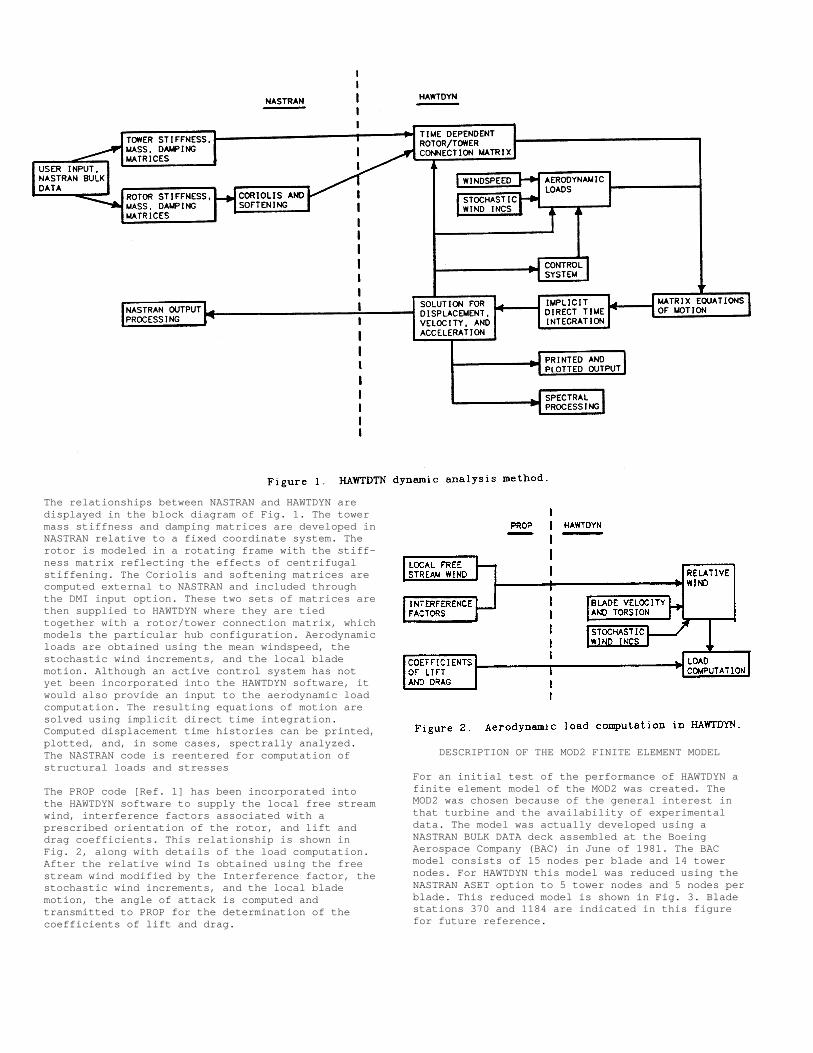
For an initial test of the performance of HAWTDYN afinite element model of the MOD2 was created. TheMOD2 was chosen because of the general interest inthat turbine and the availability of experimentaldata. The model was actually developed using aNASTRAN BULK DATA deck assembled at the BoeingAerospace Company (BAC) in June of 1981. The BACmodel consists of 15 nodes per blade and 14 towernodes. For HAWTDYN this model was reduced using theNASTRAN ASET option to 5 tower nodes and 5 nodes perblade. This reduced model is shown in Fig. 3. Bladestations 370 and 1184 are indicated in this figurefor future reference.
The tip pitch control is not modeled in an activesense in HAWTDYN, but rather the tip pitch is presetfor use in the aerodynamic load computation. Forstructural purposes the nominal pitch configurationis used in all cases. The drive train is modeledwith a spring and damper attached between the huband nacelle. The damping in the actual hardware,provided by the tip control, is not included inHAWTDYN, but approximated by setting the drive traindamper at 16% of critical. The model includes a yawspring and lateral tower damping. The values for thetower damping are set at 4% of critical for side—to—side motion, and 1% for fore—aft, consistent withmeasured results [Ref. 9].
The rotor/tower connection matrix for the MOD2 isshown in Eqn. (12). In this equation, sn representssin( Ωt) and cs, cos( Ωt). The upper case XYZsubscripts correspond to the fixed coordinatesystem, the orientation of which is shown in Fig. 3,and the lower case ones, the rotating frame.Initially, for the blade in the vertical position,these two systems coincide, with the origins of eachfixed at the hub. The rotating system turns in apositive sense about the Z axis. The U’s and θ’srepresent displacements along and rotations aboutthe respective axes.
Consistent with the MOD2 hardware, this matrixmodels a teetered hub. Retained degrees of freedomcan be identified by 1’s on the diagonal.
To examine the adequacy of this model, predictednatural frequencies for the rotor parked in thevertical position are compared to measured resultstaken from Ref. 9. The table below shows frequenciespredicted using the original BAC model and thereduced HAWTDYN model, and experimental results forseveral of the lower frequency modes. Thesefrequencies are normalized by the operating speed ofthe rotor, which is 17.5 rpm. The column labeledpercentage error corresponds to the HAWTDYN modelpredictions relative to data.
Generally, when experimental data is available,reasonably accurate models can be created bymodifying system parameters in a logical fashionsuch that the errors in the frequency predictionsare 5% or less. Most of the errors In Table 1 are ofthis order. However, for two of the modes, thesymmetric flap and the symmetric chord, the errorsare particularly high, especially considering theirimportance in the structural response of the rotor.Although not pursued here, some effort at finetuning is definitely indicated for a more accurateMOD2 model.
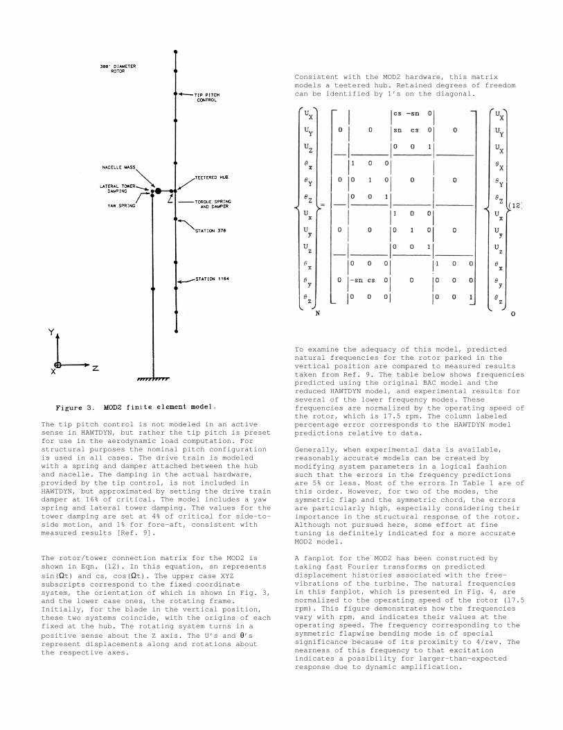
A fanplot for the MOD2 has been constructed bytaking fast Fourier transforms on predicteddisplacement histories associated with the free-vibrations of the turbine. The natural frequenciesin this fanplot, which is presented in Fig. 4, arenormalized to the operating speed of the rotor (17.5rpm). This figure demonstrates how the frequenciesvary with rpm, and indicates their values at theoperating speed. The frequency corresponding to thesymmetric flapwise bending mode is of specialsignificance because of its proximity to 4/rev. Thenearness of this frequency to that excitationindicates a possibility for larger—than—expectedresponse due to dynamic amplification.
response of the rotor to wind shear in thatcomputed displacements indicate a slight turning ofthe rotor out of the wind about a vertical axis.This motion produces a more uniform relativevelocity vector with respect to the angularposition of the rotor, and tends to neutralize theeffect of wind shear. These results arequalitatively consistent with observed behavior.
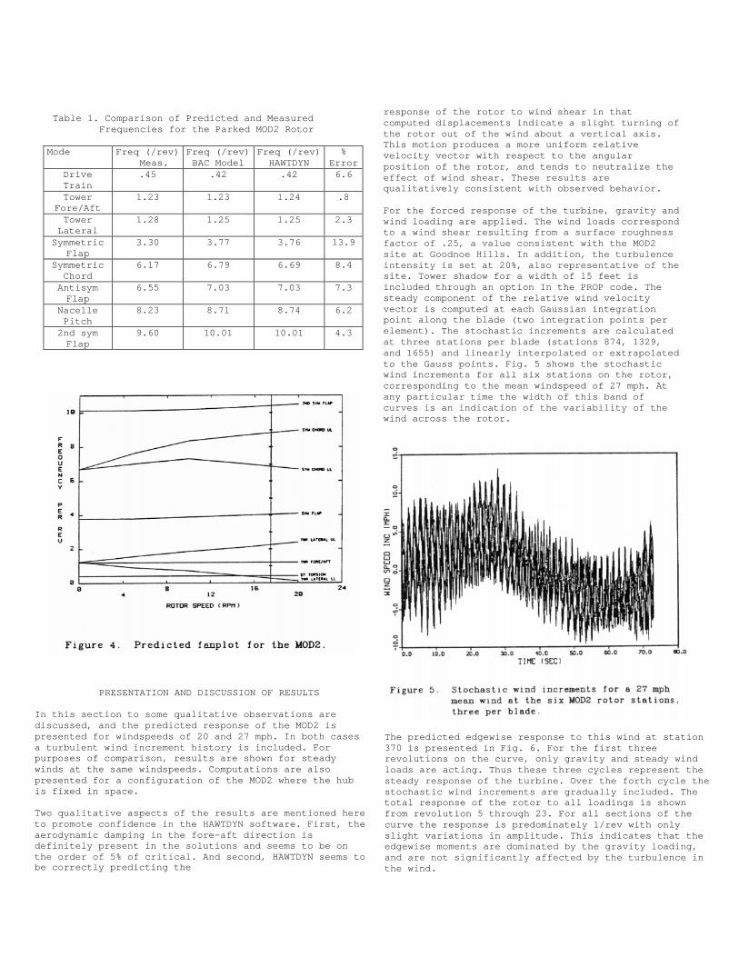
For the forced response of the turbine, gravity andwind loading are applied. The wind loads correspondto a wind shear resulting from a surface roughnessfactor of .25, a value consistent with the MOD2site at Goodnoe Hills. In addition, the turbulenceintensity is set at 20%, also representative of thesite. Tower shadow for a width of 15 feet isincluded through an option In the PROP code. Thesteady component of the relative wind velocityvector is computed at each Gaussian integrationpoint along the blade (two integration points perelement). The stochastic increments are calculatedat three stations per blade (stations 874, 1329,and 1655) and linearly interpolated or extrapolatedto the Gauss points. Fig. 5 shows the stochasticwind increments for all six stations on the rotor,corresponding to the mean windspeed of 27 mph. Atany particular time the width of this band ofcurves is an indication of the variability of thewind across the rotor.
The predicted edgewise response to this wind at station370 is presented in Fig. 6. For the first threerevolutions on the curve, only gravity and steady windloads are acting. Thus these three cycles represent thesteady response of the turbine. Over the forth cycle thestochastic wind increments are gradually included. Thetotal response of the rotor to all loadings is shownfrom revolution 5 through 23. For all sections of thecurve the response is predominately 1/rev with onlyslight variations in amplitude. This indicates that theedgewise moments are dominated by the gravity loading,and are not significantly affected by the turbulence inthe wind.
Table 1. Comparison of Predicted and MeasuredFrequencies for the Parked MOD2 Rotor
Mode Freq (/rev)Meas.
Freq (/rev)BAC Model
Freq (/rev)HAWTDYN
%Error
DriveTrain
.45 .42 .42 6.6
TowerFore/Aft
1.23 1.23 1.24 .8
TowerLateral
1.28 1.25 1.25 2.3
SymmetricFlap
3.30 3.77 3.76 13.9
SymmetricChord
6.17 6.79 6.69 8.4
AntisymFlap
6.55 7.03 7.03 7.3
NacellePitch
8.23 8.71 8.74 6.2
2nd symFlap
9.60 10.01 10.01 4.3
PRESENTATION AND DISCUSSION OF RESULTS
In this section to some qualitative observations arediscussed, and the predicted response of the MOD2 ispresented for windspeeds of 20 and 27 mph. In both casesa turbulent wind increment history is included. Forpurposes of comparison, results are shown for steadywinds at the same windspeeds. Computations are alsopresented for a configuration of the MOD2 where the hubis fixed in space.
Two qualitative aspects of the results are mentioned hereto promote confidence in the HAWTDYN software. First, theaerodynamic damping in the fore—aft direction isdefinitely present in the solutions and seems to be onthe order of 5% of critical. And second, HAWTDYN seems tobe correctly predicting the
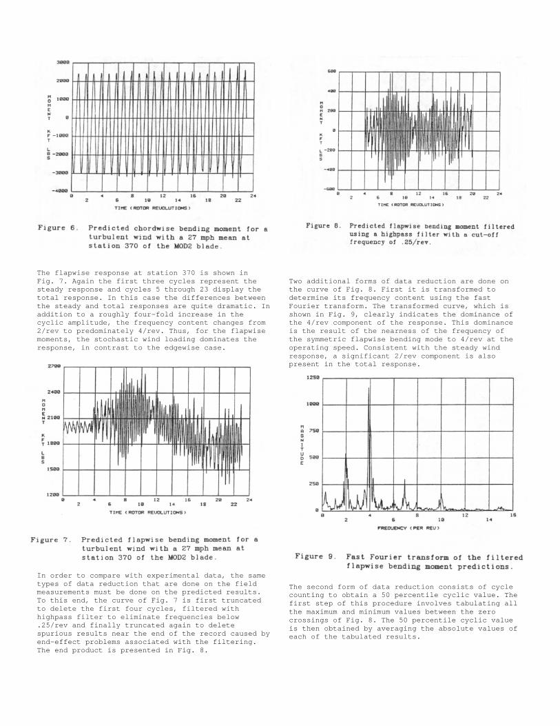
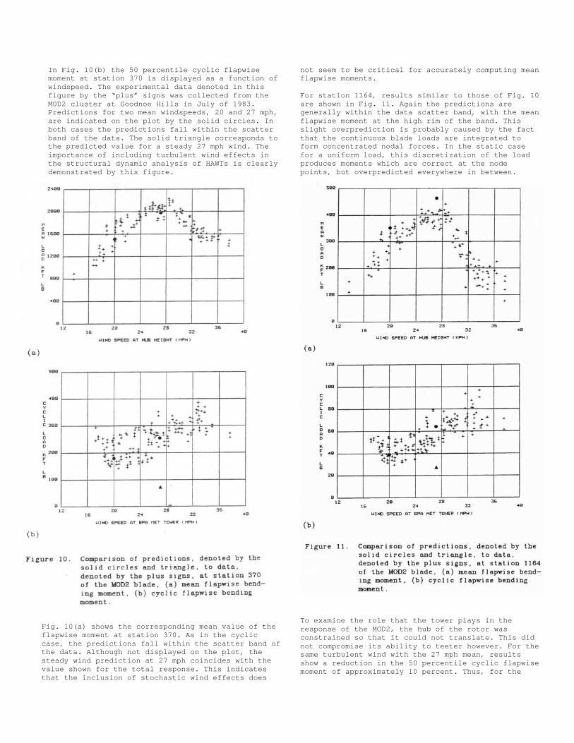
The flapwise response at station 370 is shown inFig. 7. Again the first three cycles represent thesteady response and cycles 5 through 23 display thetotal response. In this case the differences betweenthe steady and total responses are quite dramatic. Inaddition to a roughly four—fold increase in thecyclic amplitude, the frequency content changes from2/rev to predominately 4/rev. Thus, for the flapwisemoments, the stochastic wind loading dominates theresponse, in contrast to the edgewise case.
In order to compare with experimental data, the sametypes of data reduction that are done on the fieldmeasurements must be done on the predicted results.To this end, the curve of Fig. 7 is first truncatedto delete the first four cycles, filtered withhighpass filter to eliminate frequencies below.25/rev and finally truncated again to deletespurious results near the end of the record caused byend—effect problems associated with the filtering.The end product is presented in Fig. 8.
Two additional forms of data reduction are done onthe curve of Fig. 8. First it is transformed todetermine its frequency content using the fastFourier transform. The transformed curve, which isshown in Fig. 9, clearly indicates the dominance ofthe 4/rev component of the response. This dominanceis the result of the nearness of the frequency ofthe symmetric flapwise bending mode to 4/rev at theoperating speed. Consistent with the steady windresponse, a significant 2/rev component is alsopresent in the total response.
The second form of data reduction consists of cyclecounting to obtain a 50 percentile cyclic value. Thefirst step of this procedure involves tabulating allthe maximum and minimum values between the zerocrossings of Fig. 8. The 50 percentile cyclic valueis then obtained by averaging the absolute values ofeach of the tabulated results.
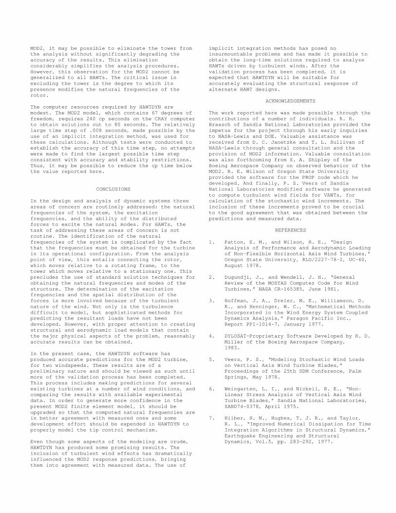
In Fig. 10(b) the 50 percentile cyclic flapwisemoment at station 370 is displayed as a function ofwindspeed. The experimental data denoted in thisfigure by the “plus” signs was collected from theM0D2 cluster at Goodnoe Hills in July of 1983.Predictions for two mean windspeeds, 20 and 27 mph,are indicated on the plot by the solid circles. Inboth cases the predictions fall within the scatterband of the data. The solid triangle corresponds tothe predicted value for a steady 27 mph wind. Theimportance of including turbulent wind effects inthe structural dynamic analysis of HAWTs is clearlydemonstrated by this figure.
Fig. 10(a) shows the corresponding mean value of theflapwise moment at station 370. As in the cycliccase, the predictions fall within the scatter band ofthe data. Although not displayed on the plot, thesteady wind prediction at 27 mph coincides with thevalue shown for the total response. This indicatesthat the inclusion of stochastic wind effects does
not seem to be critical for accurately computing meanflapwise moments.
For station 1164, results similar to those of Fig. 10are shown in Fig. 11. Again the predictions aregenerally within the data scatter band, with the meanflapwise moment at the high rim of the band. Thisslight overprediction is probably caused by the factthat the continuous blade loads are integrated toform concentrated nodal forces. In the static casefor a uniform load, this discretization of the loadproduces moments which are correct at the nodepoints, but overpredicted everywhere in between.
To examine the role that the tower plays in theresponse of the MOD2, the hub of the rotor wasconstrained so that it could not translate. This didnot compromise its ability to teeter however. For thesame turbulent wind with the 27 mph mean, resultsshow a reduction in the 50 percentile cyclic flapwisemoment of approximately 10 percent. Thus, for the
MOD2, it may be possible to eliminate the tower fromthe analysis without significantly degrading theaccuracy of the results. This eliminationconsiderably simplifies the analysis procedures.However, this observation for the MOD2 cannot begeneralized to all HAWTs. The critical issue inexcluding the tower is the degree to which itspresence modifies the natural frequencies of therotor.
The computer resources required by HAWTDYN aremodest. The MOD2 model, which contains 67 degrees offreedom, requires 240 cp seconds on the CRAY computerto obtain solutions out to 80 seconds. The relativelylarge time step of .008 seconds, made possible by theuse of an implicit integration method, was used forthese calculations. Although tests were conducted toestablish the accuracy of this time step, no attemptswere made to find the largest possible time stepconsistent with accuracy and stability restrictions.Thus, it may be possible to reduce the cp time belowthe value reported here.
CONCLUSIONS
In the design and analysis of dynamic systems threeareas of concern are routinely addressed: the naturalfrequencies of the system, the excitationfrequencies, and the ability of the distributedforces to excite the natural modes. For HAWTs, thetask of addressing these areas of concern is notroutine. The identification of the naturalfrequencies of the system is complicated by the factthat the frequencies must be obtained for the turbinein its operational configuration. From the analysispoint of view, this entails connecting the rotor,which moves relative to a rotating frame, to thetower which moves relative to a stationary one. Thisprecludes the use of standard solution techniques forobtaining the natural frequencies and modes of thestructure. The determination of the excitationfrequencies and the spatial distribution of theforces is more involved because of the turbulentnature of the wind. Not only is the turbulencedifficult to model, but sophisticated methods forpredicting the resultant loads have not beendeveloped. However, with proper attention to creatingstructural and aerodynamic load models that containthe major physical aspects of the problem, reasonablyaccurate results can be obtained.
In the present case, the HAWTDYN software hasproduced accurate predictions for the MOD2 turbine,for two windspeeds. These results are of apreliminary nature and should be viewed as such untilmore of the validation process has been completed.This process includes making predictions for severalexisting turbines at a number of wind conditions, andcomparing the results with available experimentaldata. In order to generate more confidence in thepresent MOD2 finite element model, it should beupgraded so that the computed natural frequencies arein better agreement with measured ones and somedevelopment effort should be expended in HAWTDYN toproperly model the tip control mechanism.
Even though some aspects of the modeling are crude,HAWTDYN has produced some promising results. Theinclusion of turbulent wind effects has dramaticallyinfluenced the MOD2 response predictions, bringingthem into agreement with measured data. The use of
implicit integration methods has posed noinsurmountable problems and has made it possible toobtain the long—time solutions required to analyzeHAWTs driven by turbulent winds. After thevalidation process has been completed, it isexpected that HAWTDYN will be suitable foraccurately evaluating the structural response ofalternate HAWT designs.
ACKNOWLEDGEMENTS
The work reported here was made possible through thecontributions of a number of individuals. R. H.Braasch of Sandia National Laboratories provided theimpetus for the project through his early inquiriesto NASA—Lewis and DOE. Valuable assistance wasreceived from D. C. Janetzke and T. L. Sullivan ofNASA—Lewis through general consultation and theprovision of MOD2 information. Valuable consultationwas also forthcoming from S. A. Shipley of theBoeing Aerospace Company on observed behavior of theMOD2. R. E. Wilson of Oregon State Universityprovided the software for the PROP code which hedeveloped. And finally, P. S. Veers of SandiaNational Laboratories modified software he generatedto compute turbulent wind fields for VAWTs, forcalculation of the stochastic wind increments. Theinclusion of these increments proved to be crucialto the good agreement that was obtained between thepredictions and measured data.
REFERENCES
1. Patton, E. M., and Wilson, R. E., “DesignAnalysis of Performance and Aerodynamic Loadingof Non—Flexible Horizontal Axis Wind Turbines,”Oregon State University, RLO/2227—78—2, UC—60,August 1978.
2. Dugundji, J., and Wendell, J. H., “GeneralReview of the MOSTAS Computer Code for WindTurbines,” NASA CR—165385, June 1981.
3. Hoffman, J. A., Dreier, M. E., Williamson, D.R., and Henninger, W. C., “Mathematical MethodsIncorporated in the Wind Energy System CoupledDynamics Analysis,” Paragon Pacific Inc.,Report PPI—1014—7, January 1977.
4. DYLOSAT—Proprietary Software Developed by R. D.Miller of the Boeing Aerospace Company,1983.
5. Veers, P. S., “Modeling Stochastic Wind Loadson Vertical Axis Wind Turbine Blades,”Proceedings of the 25th SDM Conference, PalmSprings, May 1978.
6. Weingarten, L. I., and Nickell, R. E., “Non-Linear Stress Analysis of Vertical Axis WindTurbine Blades,” Sandia National Laboratories,SAND74—0378, April 1975.
7. Hilber, H. N., Hughes, T. J. R., and Taylor,R. L., “Improved Numerical Dissipation for TimeIntegration Algorithms in Structural Dynamics,”Earthquake Engineering and StructuralDynamics, Vol.5, pp. 283—292, 1977.

8. Newmark, N. U., “A Method of Computation forStructural Dynamics,” Journal of the EngineeringMechanics Division, ASCE, Vol. 85, EM3, pp. 67—94, 1959.
9. Andrews, J. S., and Baskin, J. U., “DevelopmentTests for the 2.5 Megawatt MOD—2 Wind TurbineGenerator,” Proceedings of the Large Horizontal—Axis Wind Turbines Workshop, NASA ConferencePublication 2230, Cleveland, July 1981.