Embed Size (px)
Citation preview
Journal of the Indian Institute of Science
A Multidisciplinary Reviews Journal
ISSN: 0970-4140 Coden-JIISAD
© Indian Institute of Science
Journal of the Indian Institute of Science VOL 93:4 Oct.–Dec. 2013 journal.iisc.ernet.in
Rev
iew
s
Delamination Tolerance in Composites under Fatigue Loading
K. Lok Singh1 and B. Dattaguru 2*
Abstract | Delamination is one of the most commonly occurring defects in laminated composite structures. Under operating fatigue loads on the laminate this delamination could grow and totally delaminate certain number of layers from the base laminate. This will result in loss of both compressive residual strength and buckling margins available. In this paper, geometrically non-linear analysis and evaluation of Strain Energy Release Rates using MVCCI technique is presented. The problems of mul-tiple delamination, effect of temperature exposure and delamination from pin loaded holes are addressed. Numerical results are presented to draw certain inferences of importance to design of high technology composite structures such as aircraft wing.Keywords: Composite, Delamination, Fatigue.
1National Aerospace Laboratories, Post Bag No. 1779, Kodihalli, Bangalore 560017, India.2IIAEM, Jain University, Jakkasandra, Ramanagar District 562112, India.(Consultant) TechMahindra, Electronic City Phase II, Bangalore 560110, India.(Formerly) Department of Aerospace Engineering, Indian Institute of Science, Bangalore 560012, India.
1 IntroductionFiber reinforced laminated composites are increas-ingly being used in recent years in aerospace and in many other non-aerospace industries, such as, automobile, marine transport, pressure vessels, buildings and civil structures, sporting goods, medical equipment and prosthetic devices, etc. In view of the increased use of the composite mate-rials in safety critical high technology structures, there is a tremendous need to develop methods to predict the short and long-term behavior of the composite materials and structures made of these materials under a variety of service loading conditions. In the pristine condition of the fiber-reinforced composite possess excellent in-plane properties and high specific strength for carbon-epoxy composite laminate. Many primary struc-tural components of aircraft designed recently are being made of laminated composites to achieve high performance. The wing of a typical aircraft could be made of carbon composite materials to achieve low weight to strength ratio.
Examples of aircraft using carbon-epoxy com-posites for primary structures include Airbus 300–340 series, Boeing 777 transport, Light Com-bat Aircraft (LCA) made in India and B-2 military aircraft, Comanche helicopter, and satellites and various components of space shuttle (especially
the new X-33 version). The stressed skin concept in the aeronautical and aircraft industry is para-mount for maintaining the aerodynamic shape of the aircraft while minimizing the take-off weight and fuel consumption. Besides the tensile and shear loads on the wing, the thin composite shell should be designed to carry compressive loads.1,2 The incorporation of the reinforcing members will partition the skin into smaller panels, thereby increasing the buckling resistance and post-buck-ling strength.3,4 The considerations are similar for the case of the tail plane. Further the co-cured and co-bonded composite stiffened-skin concept contributes to reduced part count and excessive sub-assembly, typically encountered in traditional structures, economizing production costs.
These structures have to perform satisfactorily under expected service conditions for significantly long period of time. Delamination is considered as a crucial failure mode in laminated composites with serious consequences on residual compres-sive and buckling strength.5 Such delamination could occur either due to manufacturing defects or damage on the outer surface of the component till their size exceeds the size corresponding to Barely Visible Impact Damage (BVID) level. These defects could grow during operation and may lead to total delamination of some of the layers of the
K. Lok Singh and B. Dattaguru
Journal of the Indian Institute of Science VOL 93:4 Oct.–Dec. 2013 journal.iisc.ernet.in594
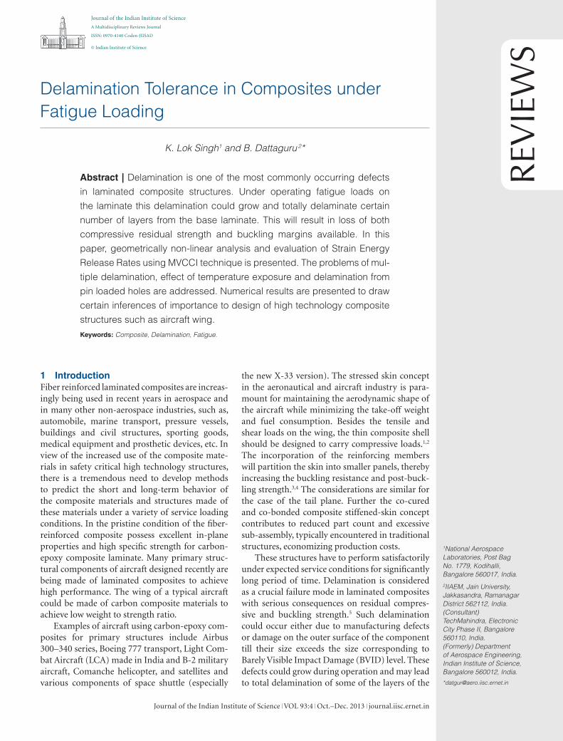
laminate. The consequences are loss of stiffness and buckling strength. In structures designed on the basis of Damage Tolerance (DT) principles the fracture parameters such as Strain Energy Release Rates (SERR) are limited to the threshold value so that any delamination present does not grow due to the operating fatigue loads.6,7 Typical through-width and circular embedded delamination1,2 are shown in Fig. 1.
The possible presence of this delamination could be crucial for design, in particular when the margins of safety are pegged at extraordinary low levels due to competitiveness to achieve high per-formance flight vehicles. It is significant to under-stand all aspects related to delamination tolerance, which is more complex compared to damage or crack tolerance in metallic structures.
In this paper, problems of multiple delami-nation, effect of temperature exposure and dela-mination from pin loaded holes are addressed. Numerical results are presented to draw certain inferences of importance to design of composite structures such as aircraft wing.
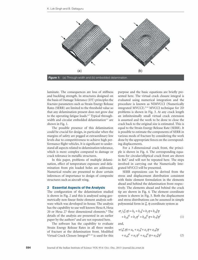
2 Essential Aspects of the AnalysisThe configuration of the delamination studied is shown in Fig. 2 and this is analyzed using geo-metrically non-linear finite element analysis soft-ware which was developed in-house. The analysis has the capability to use well known Hexa 8, Hexa 20 or Hexa 27 three dimensional elements.8 The details of the analysis are presented in an earlier paper by the authors9 and are not repeated here.
The software has the capability to evaluate Strain Energy Release Rates in all three modes of fracture at the delamination front. Modified Virtual Crack Closure Integral10–13 is used for this
purpose and the basic equations are briefly pre-sented here. The virtual crack closure integral is evaluated using numerical integration and the procedure is known as NIMVCCI (Numerically integrated MVCCI).9,14 MVCCI technique for 2D problems is shown in Fig. 3. At any crack length an infinitesimally small virtual crack extension is assumed and the work to be done to close the crack back to the original size is estimated. This is equal to the Strain Energy Release Rate (SERR). It is possible to estimate the components of SERR in various mods of fracture by considering the work done by the appropriate forces on the correspond-ing displacements.
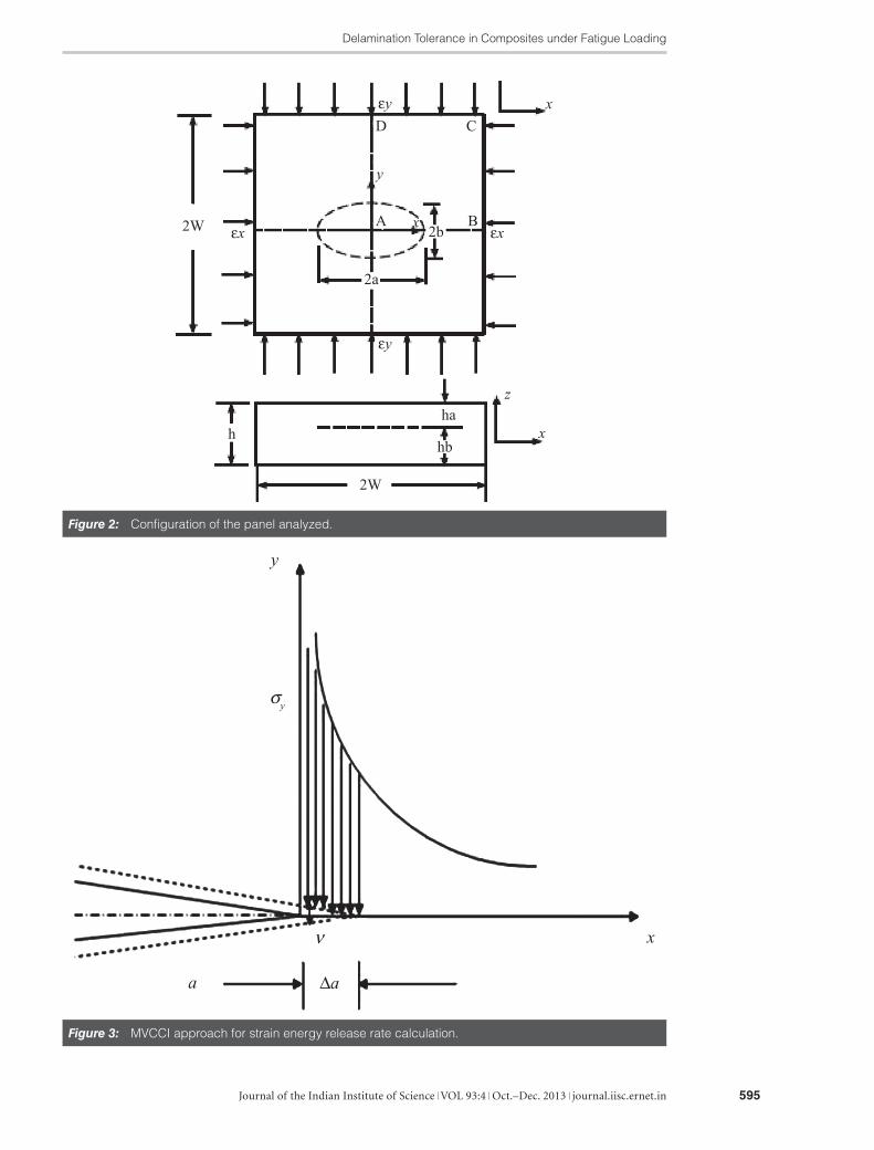
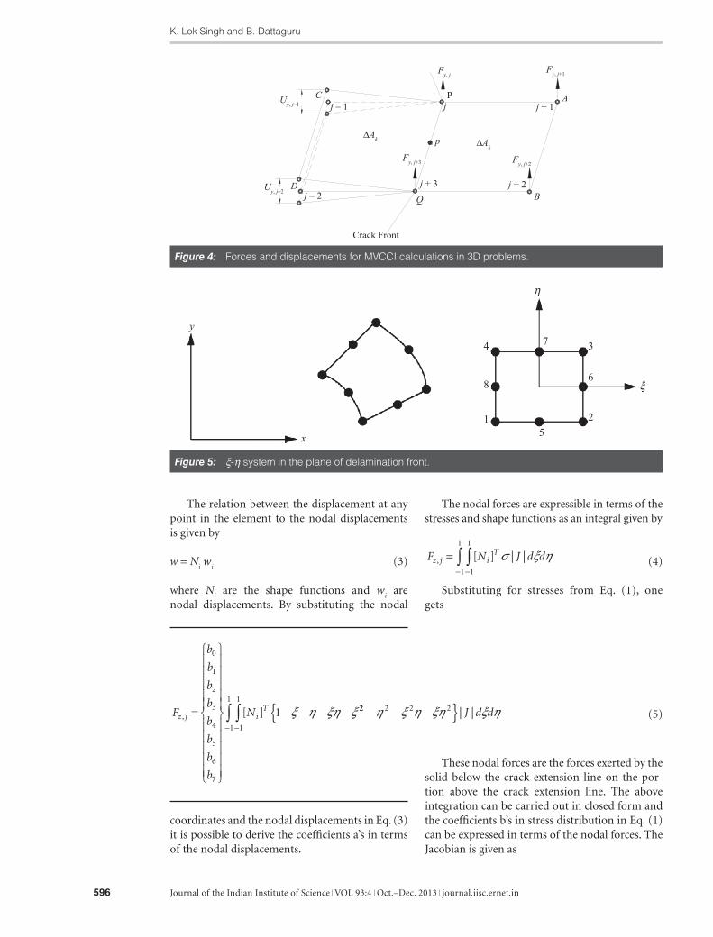
For a 3-dimensional crack front, the princi-ple is shown in Fig. 4. The corresponding equa-tions for circular/elliptical crack front are shown in Ref.9 and will not be repeated here. The steps involved in carrying out the Numerically Inte-grated MVCCI will be presented.
SERR expressions can be derived from the stress and displacement distribution consistent with finite element formulation in the elements ahead and behind the delamination front respec-tively. The elements ahead and behind the crack tip are shown in Fig. 4. The element coordinate system is shown in Fig. 5. Both the displacement and stress distributions can be assumed in simple polynomial form in ξ, η coordinate system as
σ ξ η ξ η ξη
ξ η ξ η ξηz b b b b
b b b b
( , ) = + + +
+ + + +0 1 2 3
42
52
62
72 (1)
and,
w a a a a
a a a a
( , )ξ η ξ η ξη
ξ η ξ η ξη
= + + +
+ + + +0 1 2 3
42
52
62
72 (2)
Figure 1: (a) Through-width and (b) embedded delamination.
Delamination Tolerance in Composites under Fatigue Loading
Journal of the Indian Institute of Science VOL 93:4 Oct.–Dec. 2013 journal.iisc.ernet.in 595
Figure 3: MVCCI approach for strain energy release rate calculation.
Figure 2: Configuration of the panel analyzed.
K. Lok Singh and B. Dattaguru
Journal of the Indian Institute of Science VOL 93:4 Oct.–Dec. 2013 journal.iisc.ernet.in596
The relation between the displacement at any point in the element to the nodal displacements is given by
w = Ni w
i (3)
where Ni are the shape functions and w
i are
nodal displacements. By substituting the nodal
Figure 4: Forces and displacements for MVCCI calculations in 3D problems.
Figure 5: ξ-η system in the plane of delamination front.
The nodal forces are expressible in terms of the stresses and shape functions as an integral given by
F N J d dz j iT
, [ ] | |=−−∫∫ σ ξ η1
1
1
1
(4)
Substituting for stresses from Eq. (1), one gets
F
b
b
b
b
b
b
b
b
Nz j iT
, [ ]=
0
1
2
3
4
5
6
7
1 ξ η ξη ξ 22 2 2 2
1
1
1
1
η ξ η ξη ξ η{ }−−∫∫ | |J d d (5)
These nodal forces are the forces exerted by the solid below the crack extension line on the por-tion above the crack extension line. The above integration can be carried out in closed form and the coefficients b’s in stress distribution in Eq. (1) can be expressed in terms of the nodal forces. The Jacobian is given as
coordinates and the nodal displacements in Eq. (3) it is possible to derive the coefficients a’s in terms of the nodal displacements.
Delamination Tolerance in Composites under Fatigue Loading
Journal of the Indian Institute of Science VOL 93:4 Oct.–Dec. 2013 journal.iisc.ernet.in 597
where ∆Ak is the average of the areas of the elements
ahead and behind the crack front. The expressions for mode-II and mode-III components can be written on similar lines. Gaussian numerical inte-gration was carried out on the integrals in Eq. (7).
3 Problems and Numerical Results3.1 3D Non-linear analysis of cantilever
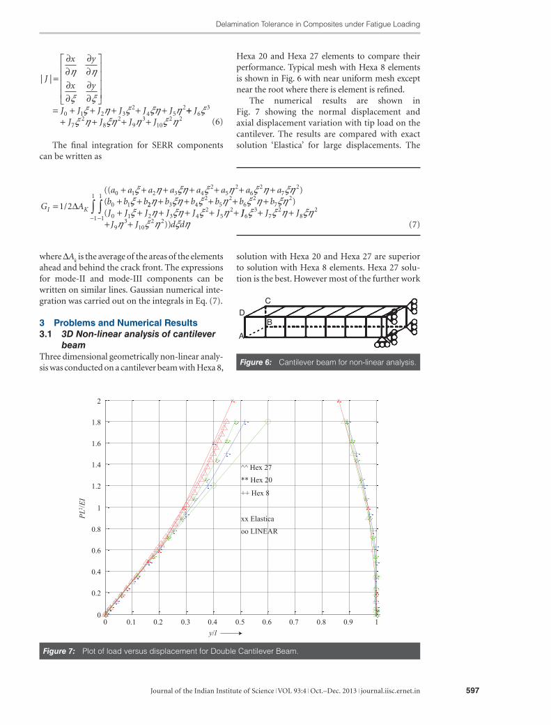
beamThree dimensional geometrically non-linear analy-sis was conducted on a cantilever beam with Hexa 8,
Hexa 20 and Hexa 27 elements to compare their performance. Typical mesh with Hexa 8 elements is shown in Fig. 6 with near uniform mesh except near the root where there is element is refined.
The numerical results are shown in Fig. 7 showing the normal displacement and axial displacement variation with tip load on the cantilever. The results are compared with exact solution ‘Elastica’ for large displacements. The
Figure 6: Cantilever beam for non-linear analysis.
Figure 7: Plot of load versus displacement for Double Cantilever Beam.
| |J
x y
x y
J J J J J J
=
∂∂
∂∂
∂∂
∂∂
= + + + + +
η η
ξ ξξ η ξ ξη η0 1 2 3
24 5
2+++ + + +
JJ J J J
63
72
82
93
102 2
ξξ η ξη η ξ η (6)
The final integration for SERR components can be written as
G A
a a a a a a a ab b b
I K=
+ + + + + + ++ +1 2
0 1 2 3 42
52
62
72
0 1/
(( )(∆
ξ η ξη ξ η ξ η ξηξ 22 3 4
25
26
27
2
0 1 2 3 42
52
η ξη ξ η ξ η ξηξ η ξη ξ η
+ + + + ++ + + + + +
b b b b bJ J J J J J
)( JJ J J
J J d d6
37
28
2
93
102 21
1
1
1
ξ ξ η ξηη ξ η ξ η
+ ++ +
−−∫∫
)) (7)
solution with Hexa 20 and Hexa 27 are superior to solution with Hexa 8 elements. Hexa 27 solu-tion is the best. However most of the further work
K. Lok Singh and B. Dattaguru
Journal of the Indian Institute of Science VOL 93:4 Oct.–Dec. 2013 journal.iisc.ernet.in598
is done with Hexa 20 elements which are popular in most of the FEM programs. This solution is presented to validate the geometrically non-lin-ear analysis.
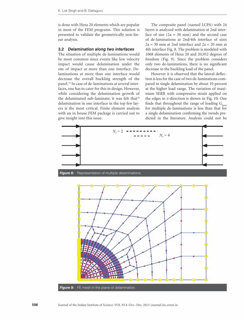
3.2 Delamination along two interfacesThe situation of multiple de-laminations would be most common since events like low velocity impact would cause delamination under the site of impact at more than one interface. De-laminations at more than one interface would decrease the overall buckling strength of the panel.15 In case of de-laminations at several inter-faces, one has to cater for this in design. However, while considering the delamination growth of the delaminated sub-laminate, it was felt that16 delamination in one interface in the top few lay-ers is the most critical. Finite element analysis with an in house FEM package is carried out to give insight into this issue.
Figure 9: FE mesh in the plane of delamination.
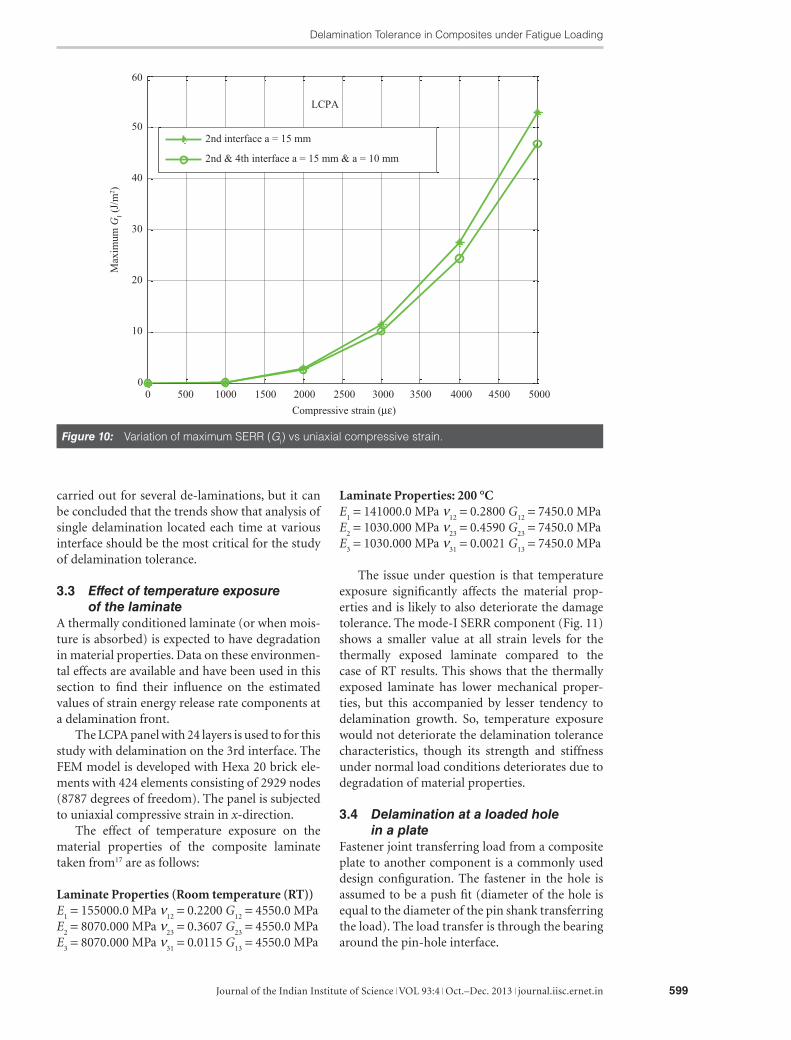
The composite panel (named LCPA) with 24 layers is analyzed with delamination at 2nd inter-face of size (2a = 30 mm) and the second case of de-laminations at 2nd/4th interface of sizes 2a = 30 mm at 2nd interface and 2a = 20 mm at 4th interface Fig. 8. The problem is modeled with 1068 elements of Hexa 20 and 20,952 degrees of freedom (Fig. 9). Since the problem considers only two de-laminations, there is no significant decrease in the buckling load of the panel.
However it is observed that the lateral deflec-tion is less for the case of two de-laminations com-pared to single delamination by about 10 percent at the higher load range. The variation of maxi-mum SERR with compressive strain applied on the edges in x-direction is shown in Fig. 10. One finds that throughout the range of loading G
Imax
for multiple de-laminations is less than that for a single delamination confirming the trends pre-dicted in the literature. Analysis could not be
Figure 8: Representation of multiple delaminations.
Delamination Tolerance in Composites under Fatigue Loading
Journal of the Indian Institute of Science VOL 93:4 Oct.–Dec. 2013 journal.iisc.ernet.in 599
carried out for several de-laminations, but it can be concluded that the trends show that analysis of single delamination located each time at various interface should be the most critical for the study of delamination tolerance.
3.3 Effect of temperature exposure of the laminate
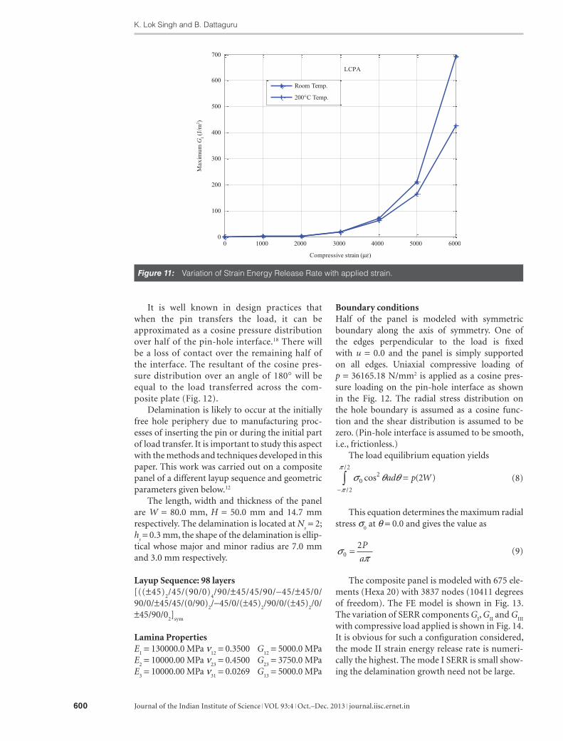
A thermally conditioned laminate (or when mois-ture is absorbed) is expected to have degradation in material properties. Data on these environmen-tal effects are available and have been used in this section to find their influence on the estimated values of strain energy release rate components at a delamination front.
The LCPA panel with 24 layers is used to for this study with delamination on the 3rd interface. The FEM model is developed with Hexa 20 brick ele-ments with 424 elements consisting of 2929 nodes (8787 degrees of freedom). The panel is subjected to uniaxial compressive strain in x-direction.
The effect of temperature exposure on the material properties of the composite laminate taken from17 are as follows:
Laminate Properties (Room temperature (RT))E
1 = 155000.0 MPa ν
12 = 0.2200 G
12 = 4550.0 MPa
E2 = 8070.000 MPa ν
23 = 0.3607 G
23 = 4550.0 MPa
E3 = 8070.000 MPa ν
31 = 0.0115 G
13 = 4550.0 MPa
Laminate Properties: 200 °CE
1 = 141000.0 MPa ν
12 = 0.2800 G
12 = 7450.0 MPa
E2 = 1030.000 MPa ν
23 = 0.4590 G
23 = 7450.0 MPa
E3 = 1030.000 MPa ν
31 = 0.0021 G
13 = 7450.0 MPa
The issue under question is that temperature exposure significantly affects the material prop-erties and is likely to also deteriorate the damage tolerance. The mode-I SERR component (Fig. 11) shows a smaller value at all strain levels for the thermally exposed laminate compared to the case of RT results. This shows that the thermally exposed laminate has lower mechanical proper-ties, but this accompanied by lesser tendency to delamination growth. So, temperature exposure would not deteriorate the delamination tolerance characteristics, though its strength and stiffness under normal load conditions deteriorates due to degradation of material properties.
3.4 Delamination at a loaded hole in a plate
Fastener joint transferring load from a composite plate to another component is a commonly used design configuration. The fastener in the hole is assumed to be a push fit (diameter of the hole is equal to the diameter of the pin shank transferring the load). The load transfer is through the bearing around the pin-hole interface.
Figure 10: Variation of maximum SERR (GI) vs uniaxial compressive strain.
K. Lok Singh and B. Dattaguru
Journal of the Indian Institute of Science VOL 93:4 Oct.–Dec. 2013 journal.iisc.ernet.in600
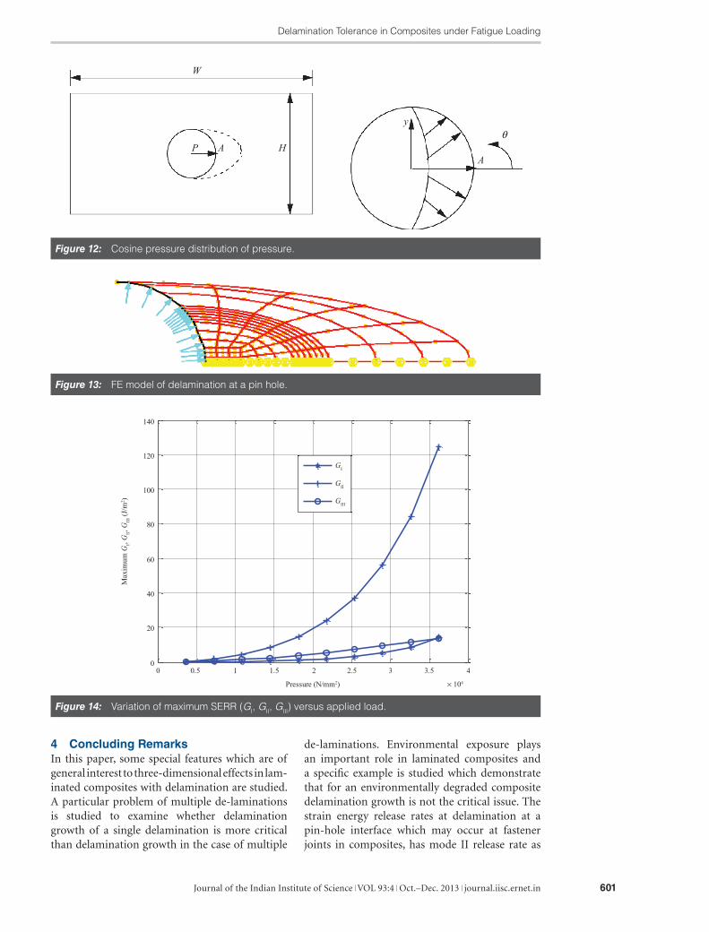
It is well known in design practices that when the pin transfers the load, it can be approximated as a cosine pressure distribution over half of the pin-hole interface.18 There will be a loss of contact over the remaining half of the interface. The resultant of the cosine pres-sure distribution over an angle of 180° will be equal to the load transferred across the com-posite plate (Fig. 12).
Delamination is likely to occur at the initially free hole periphery due to manufacturing proc-esses of inserting the pin or during the initial part of load transfer. It is important to study this aspect with the methods and techniques developed in this paper. This work was carried out on a composite panel of a different layup sequence and geometric parameters given below.12
The length, width and thickness of the panel are W = 80.0 mm, H = 50.0 mm and 14.7 mm respectively. The delamination is located at N
s = 2;
hs = 0.3 mm, the shape of the delamination is ellip-
tical whose major and minor radius are 7.0 mm and 3.0 mm respectively.
Layup Sequence: 98 layers[((±45)
2/45/(90/0)
4/90/±45/45/90/-45/±45/0/
90/0/±45/45/(0/90)2/-45/0/(±45)
2/90/0/(±45)
2/0/
±45/90/02]
sym
Lamina PropertiesE
1 = 130000.0 MPa ν
12 = 0.3500 G
12 = 5000.0 MPa
E2 = 10000.00 MPa ν
23 = 0.4500 G
23 = 3750.0 MPa
E3 = 10000.00 MPa ν
31 = 0.0269 G
13 = 5000.0 MPa
Boundary conditionsHalf of the panel is modeled with symmetric boundary along the axis of symmetry. One of the edges perpendicular to the load is fixed with u = 0.0 and the panel is simply supported on all edges. Uniaxial compressive loading of p = 36165.18 N/mm2 is applied as a cosine pres-sure loading on the pin-hole interface as shown in the Fig. 12. The radial stress distribution on the hole boundary is assumed as a cosine func-tion and the shear distribution is assumed to be zero. (Pin-hole interface is assumed to be smooth, i.e., frictionless.)
The load equilibrium equation yields
σ θ θπ
π
02
2
2
2cos ( )/
/
ad p W−∫ = (8)
This equation determines the maximum radial stress σ
0 at θ = 0.0 and gives the value as
σπ0
2=
P
a (9)
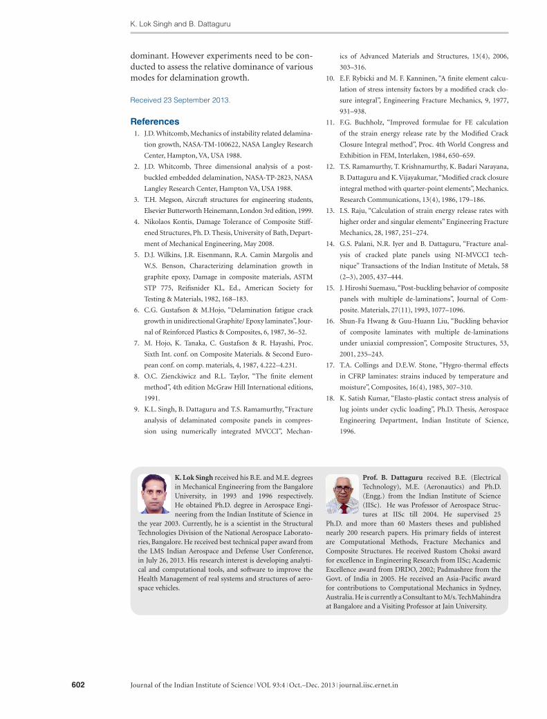
The composite panel is modeled with 675 ele-ments (Hexa 20) with 3837 nodes (10411 degrees of freedom). The FE model is shown in Fig. 13. The variation of SERR components G
I, G
II and G
III
with compressive load applied is shown in Fig. 14. It is obvious for such a configuration considered, the mode II strain energy release rate is numeri-cally the highest. The mode I SERR is small show-ing the delamination growth need not be large.
Figure 11: Variation of Strain Energy Release Rate with applied strain.
Delamination Tolerance in Composites under Fatigue Loading
Journal of the Indian Institute of Science VOL 93:4 Oct.–Dec. 2013 journal.iisc.ernet.in 601
4 Concluding RemarksIn this paper, some special features which are of general interest to three-dimensional effects in lam-inated composites with delamination are studied. A particular problem of multiple de-laminations is studied to examine whether delamination growth of a single delamination is more critical than delamination growth in the case of multiple
de-laminations. Environmental exposure plays an important role in laminated composites and a specific example is studied which demonstrate that for an environmentally degraded composite delamination growth is not the critical issue. The strain energy release rates at delamination at a pin-hole interface which may occur at fastener joints in composites, has mode II release rate as
Figure 14: Variation of maximum SERR (GI, GII, GIII) versus applied load.
Figure 12: Cosine pressure distribution of pressure.
Figure 13: FE model of delamination at a pin hole.
K. Lok Singh and B. Dattaguru
Journal of the Indian Institute of Science VOL 93:4 Oct.–Dec. 2013 journal.iisc.ernet.in602
dominant. However experiments need to be con-ducted to assess the relative dominance of various modes for delamination growth.
Received 23 September 2013.
References 1. J.D. Whitcomb, Mechanics of instability related delamina-
tion growth, NASA-TM-100622, NASA Langley Research
Center, Hampton, VA, USA 1988.
2. J.D. Whitcomb, Three dimensional analysis of a post-
buckled embedded delamination, NASA-TP-2823, NASA
Langley Research Center, Hampton VA, USA 1988.
3. T.H. Megson, Aircraft structures for engineering students,
Elsevier Butterworth Heinemann, London 3rd edition, 1999.
4. Nikolaos Kontis, Damage Tolerance of Composite Stiff-
ened Structures, Ph. D. Thesis, University of Bath, Depart-
ment of Mechanical Engineering, May 2008.
5. D.J. Wilkins, J.R. Eisenmann, R.A. Camin Margolis and
W.S. Benson, Characterizing delamination growth in
graphite epoxy, Damage in composite materials, ASTM
STP 775, Reifisnider KL, Ed., American Society for
Testing & Materials, 1982, 168–183.
6. C.G. Gustafson & M.Hojo, “Delamination fatigue crack
growth in unidirectional Graphite/ Epoxy laminates”, Jour-
nal of Reinforced Plastics & Composites, 6, 1987, 36–52.
7. M. Hojo, K. Tanaka, C. Gustafson & R. Hayashi, Proc.
Sixth Int. conf. on Composite Materials. & Second Euro-
pean conf. on comp. materials, 4, 1987, 4.222–4.231.
8. O.C. Zienckiwicz and R.L. Taylor, “The finite element
method”, 4th edition McGraw Hill International editions,
1991.
9. K.L. Singh, B. Dattaguru and T.S. Ramamurthy, “Fracture
analysis of delaminated composite panels in compres-
sion using numerically integrated MVCCI”, Mechan-
ics of Advanced Materials and Structures, 13(4), 2006,
303–316.
10. E.F. Rybicki and M. F. Kanninen, “A finite element calcu-
lation of stress intensity factors by a modified crack clo-
sure integral”, Engineering Fracture Mechanics, 9, 1977,
931–938.
11. F.G. Buchholz, “Improved formulae for FE calculation
of the strain energy release rate by the Modified Crack
Closure Integral method”, Proc. 4th World Congress and
Exhibition in FEM, Interlaken, 1984, 650–659.
12. T.S. Ramamurthy, T. Krishnamurthy, K. Badari Narayana,
B. Dattaguru and K. Vijayakumar, “Modified crack closure
integral method with quarter-point elements”, Mechanics.
Research Communications, 13(4), 1986, 179–186.
13. I.S. Raju, “Calculation of strain energy release rates with
higher order and singular elements” Engineering Fracture
Mechanics, 28, 1987, 251–274.
14. G.S. Palani, N.R. Iyer and B. Dattaguru, “Fracture anal-
ysis of cracked plate panels using NI-MVCCI tech-
nique” Transactions of the Indian Institute of Metals, 58
(2–3), 2005, 437–444.
15. J. Hiroshi Suemasu, “Post-buckling behavior of composite
panels with multiple de-laminations”, Journal of Com-
posite. Materials, 27(11), 1993, 1077–1096.
16. Shun-Fa Hwang & Guu-Huann Liu, “Buckling behavior
of composite laminates with multiple de-laminations
under uniaxial compression”, Composite Structures, 53,
2001, 235–243.
17. T.A. Collings and D.E.W. Stone, “Hygro-thermal effects
in CFRP laminates: strains induced by temperature and
moisture”, Composites, 16(4), 1985, 307–310.
18. K. Satish Kumar, “Elasto-plastic contact stress analysis of
lug joints under cyclic loading”, Ph.D. Thesis, Aerospace
Engineering Department, Indian Institute of Science,
1996.
Prof. B. Dattaguru received B.E. (Electrical Technology), M.E. (Aeronautics) and Ph.D. (Engg.) from the Indian Institute of Science (IISc). He was Professor of Aerospace Struc-tures at IISc till 2004. He supervised 25
Ph.D. and more than 60 Masters theses and published nearly 200 research papers. His primary fields of interest are Computational Methods, Fracture Mechanics and Composite Structures. He received Rustom Choksi award for excellence in Engineering Research from IISc; Academic Excellence award from DRDO, 2002; Padmashree from the Govt. of India in 2005. He received an Asia-Pacific award for contributions to Computational Mechanics in Sydney, Australia. He is currently a Consultant to M/s. TechMahindra at Bangalore and a Visiting Professor at Jain University.
K. Lok Singh received his B.E. and M.E. degrees in Mechanical Engineering from the Bangalore University, in 1993 and 1996 respectively. He obtained Ph.D. degree in Aerospace Engi-neering from the Indian Institute of Science in
the year 2003. Currently, he is a scientist in the Structural Technologies Division of the National Aerospace Laborato-ries, Bangalore. He received best technical paper award from the LMS Indian Aerospace and Defense User Conference, in July 26, 2013. His research interest is developing analyti-cal and computational tools, and software to improve the Health Management of real systems and structures of aero-space vehicles.