Embed Size (px)
Citation preview
Materials and Design 24(2003) 15–24
0261-3069/03/$ - see front matter� 2002 Elsevier Science Ltd. All rights reserved.PII: S0261-3069Ž02.00087-0
A multiaxial failure criterion for a brittle orthotropic composite
Catherine Davy *, Didier Marquisa, b
Cambridge Centre for Micromechanics, Cambridge University Engineering Department, Trumpington Street, Cambridge CB2 1PZ, UKa
IFMA, Campus des Cezeaux, BP 265, 63175 Aubiere Cedex, Franceb ´ `
Received 10 July 2002; received in revised form 3 October 2002; accepted 12 October 2002
Abstract
A multiaxial failure criterion is validated for a brittle orthotropic composite, namely a tridirectional carbon–carbon composite(3D C–C). It is aimed at designers of 3D C–C structures. The composite is subjected to a triaxial strain state along itsreinforcement axes, which is representative of its in-service loading conditions. A multiaxial test rig is designed in order toreproduce this required strain state. Its mock-up dimensions are optimised by combining Taguchi experimental strategy withtridimensional finite element modelling. Comparison of experimental results with numerical modelling shows that failure occursdue to the required strain state; failure is brittle and corresponds to simultaneous breakage of carbon yarns along the threereinforcement axes. Subsequently, the experiment validates a failure criterion, which assumes linear coupling between the threeprincipal strains.� 2002 Elsevier Science Ltd. All rights reserved.
Keywords: Carbon–carbon composite; Failure prediction; Experimental strategy
1. Introduction
Tridirectional carbon–carbon composites(3D C–C)are especially designed for high temperature applicationsw18,21x, as they keep their mechanical properties attemperatures above 30008C, outperforming any othermaterial. Multiaxial extension along their three rein-forcement axes at ambient temperature is assumed to bea good representation of their high temperature in-service loading conditionsw6x, for which accurate failureprediction is essential. Early experimental studies onthose orthotropic composites have focused on the effectsof processing upon composite microstructure and ther-momechanical behaviourw1,5,16,19,24x. Various dam-age and failure models are also availablew2–4,11,15,20x.Firstly, the brittle composite multiaxial failure isassumed deterministic by analogy with uniaxial failure.Indeed the composite failure strength along each rein-forcement axis, denotedx, y or z, exhibits a negligiblescatter, see Davy and Marquisw10x. Secondly, under
*Corresponding author. Tel.:q44-1223-339883; fax:q44-1223-332662.
E-mail addresses: [email protected](C. Davy),[email protected](D. Marquis).
extension along one or several reinforcement axes,failure prediction is based on the following Rankine-type criterion: a brittle-type failure occurs when ultimatestrain is reached along any single reinforcement axisw11x. No coupling is assumed between ultimate strainsalongx, y or z: failure occurs independently along eachreinforcement axis, as if multiaxial loading alongx, yandz was the simple superposition of three independentextensions along each axis. Yet failure criterionw11x hasnot been validated experimentally regarding multiaxialextension: does it accurately describe the compositefailure when it is subjected to simultaneous extensionalong x, y and z? Or is there any coupling betweenultimate strains along the reinforcement axes? This paperaddresses these questions through the comparison offailure criterion w11x to the experimental multiaxial 3DC–C response(this process is usually called experimen-tal validation of the criterion), as follows.Several mock-up designsw12,17x exist to reproduce
multiaxial strain states through a mechanical loading.They are based on the superposition of three uniaxialtensile specimens linked by transition radii. However,none is adapted to brittle composite testing: should anymock-up misalignment occur, premature failure would
16 C. Davy, D. Marquis / Materials and Design 24 (2003) 15–24
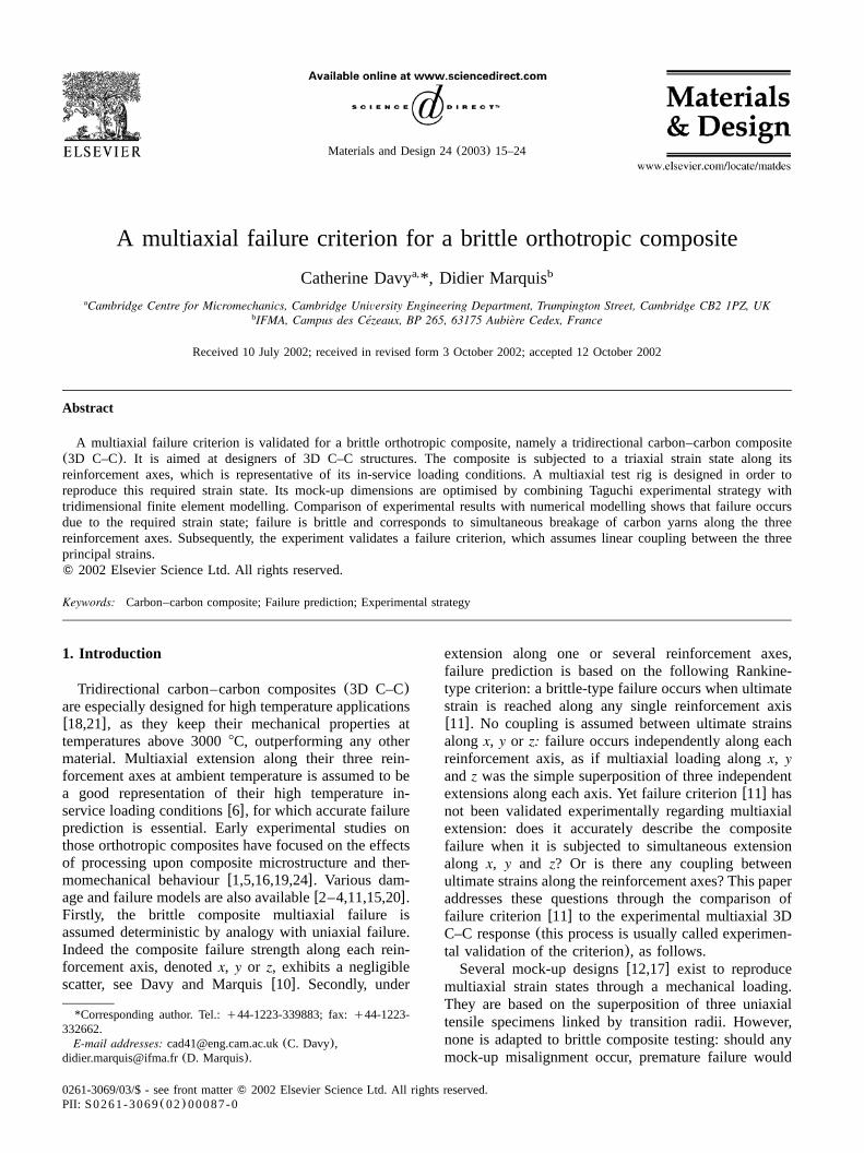
Fig. 1. The 3D C–C composite is made of continuous PAN-basedcarbon yarns and pitch-based carbon matrix. Yarns are aligned in threeorthogonal directions denotedx, y andz. Axesx andy have equivalentcomposition with a yarn cross-sectional area of 0.4=0.8 mm , where-2
asz-axis yarn cross-sectional area is twice that ofx- andy-axis yarns.Carbon matrix fills up the gaps, which are called matrix blocksw10x.
take place at the transition radii due to stress concentra-tion effects. Hence, we designed a new test rig, basedon an original initial choice for the mock-up shape: itis the superposition of a uniaxial tensile specimenperpendicular to a square plate subjected to equibiaxialbending. Premature failure is avoided by allowing themock-up small movements which compensate misalign-ments. The exact mock-up dimensions are locally optim-ised (a set of assumptions is made) using thecombination of tridimensional finite element modellingand Taguchi experimental strategy. This test strategyallows to minimise computation times and to evaluatethe effect of several interacting parameters upon theoptimisation criterion.Once the test rig is fully designed and manufactured,
a mock-up made of 3D C–C is brought to failure. Itsresponse is qualified: we check that the required loadingconditions are applied to the mock-up, and that itactually fails under triaxial extension. Finally, the pre-diction of failure criterion w11x is shown to largelyoverestimate the experimental 3D C–C response: undertriaxial extension, coupling actually exists between ulti-mate strains along axesx, y and z. We propose a novelfailure criterion which incorporates this feature.In the following, the composite is described, and the
multiaxial test rig design is presented(Section 2). Wealso expose the mock-up optimisation method. In Sec-tion 3, an experiment on a 3D C–C mock-up is qualified;results show that a brittle-type failure actually occursunder tridirectional extension of the composite, andfailure is due to yarn breakages along the three reinforce-ment axes. The adequacy of failure criterionw11x is theninvestigated. Concluding remarks are given in Section4.
2. Experimental
Although our test method is suitable for any brittleorthotropic material, this study focuses on a 3D C–Ccomposite which is described hereafter. The mock-updesign is then detailed, and that of the correspondingloading set-up; adapted measurement and test procedureare also selected. Additionally, we expose the methodimplemented in order to optimise the mock-updimensions.
2.1. Description of the material
The 3D C–C studied herein is made of PAN -based1
carbon yarns impregnated with pitch-based carbonmatrix. The composite architecture is similar to that ofAerolor 32 manufactured by EADSwII x, see Fig. 1:2´
PAN is a conventional abbreviation for PolyAcryloNitrile.1
EADS stands for European Aeronautic Defence and Space Com-2
pany and comprises the former French aeronautical company Aero-spatiale which originated several 3D C–Cs like Aerolor 32.
continuous yarns are aligned along three orthogonaldirections of space, denotedx, y and z; the two yarndirectionsx andy are equivalent. Reinforcement axesx,y and z are also principal orthotropy axes for thecomposite. When loaded in tension(or extension) alonga single reinforcement axis, the 3D C–C displays abrittle-type failurew10,11,20x.Usually, a linear orthotropic Hooke’s law describes
the 3D C–C initial mechanical behaviourw11x. It is notmodified during tests along the principal axes as thecomposite does not damage. In that case, as the 3D C–CPoisson’s ratio is close to zerowII x, principal stressesand strains are proportional. Therefore, in the following,extensional or tensile loadings along the principal axesare assimilated.
2.2. Design of a multiaxial test rig
In order to reproduce its in-service critical loadingconditions, we aim to bring to failure the brittle ortho-tropic composite under a triaxial strain state Fig. 2, suchthat:
´ sa=´ sa=´zz xx yy
where´ (resp.´ , ´ ) is the composite strain alongxx yy zz
reinforcement axisx (resp.y, z). ´ equals´ as axesxx yy
x andy are equivalent. Shear strains´ , ´ and´ arexy xz yz
negligible: ´ , ´ and ´ are principal strains for thexx yy zz
composite. However, this multiaxial strain state cannotbe achieved using existing mock-up designsw12,17x asthey cannot prevent brittle materials premature failurein case of misalignment with the loading set-up. Hence,a complete test rig was designedw7x, as follows. Asuitable measurement and test procedure was alsoselected.
17C. Davy, D. Marquis / Materials and Design 24 (2003) 15–24
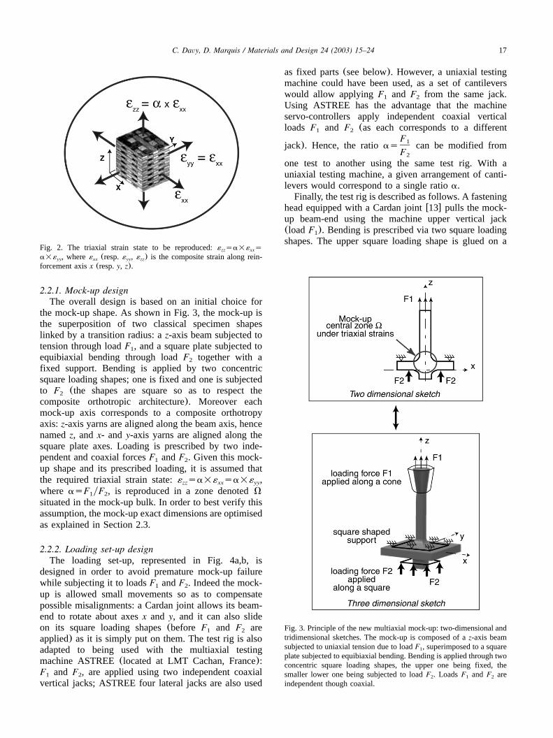
Fig. 2. The triaxial strain state to be reproduced:´ sa=´ szz xx
a=´ , where´ (resp.´ , ´ ) is the composite strain along rein-yy xx yy zz
forcement axisx (resp.y, z).
Fig. 3. Principle of the new multiaxial mock-up: two-dimensional andtridimensional sketches. The mock-up is composed of az-axis beamsubjected to uniaxial tension due to loadF , superimposed to a square1
plate subjected to equibiaxial bending. Bending is applied through twoconcentric square loading shapes, the upper one being fixed, thesmaller lower one being subjected to loadF . LoadsF and F are2 1 2
independent though coaxial.
2.2.1. Mock-up designThe overall design is based on an initial choice for
the mock-up shape. As shown in Fig. 3, the mock-up isthe superposition of two classical specimen shapeslinked by a transition radius: az-axis beam subjected totension through loadF , and a square plate subjected to1
equibiaxial bending through loadF together with a2
fixed support. Bending is applied by two concentricsquare loading shapes; one is fixed and one is subjectedto F (the shapes are square so as to respect the2
composite orthotropic architecture). Moreover eachmock-up axis corresponds to a composite orthotropyaxis:z-axis yarns are aligned along the beam axis, hencenamedz, andx- and y-axis yarns are aligned along thesquare plate axes. Loading is prescribed by two inde-pendent and coaxial forcesF andF . Given this mock-1 2
up shape and its prescribed loading, it is assumed thatthe required triaxial strain state: sa=´ sa=´ ,zz xx yy
whereasF yF , is reproduced in a zone denotedV1 2
situated in the mock-up bulk. In order to best verify thisassumption, the mock-up exact dimensions are optimisedas explained in Section 2.3.
2.2.2. Loading set-up designThe loading set-up, represented in Fig. 4a,b, is
designed in order to avoid premature mock-up failurewhile subjecting it to loadsF andF . Indeed the mock-1 2
up is allowed small movements so as to compensatepossible misalignments: a Cardan joint allows its beam-end to rotate about axesx and y, and it can also slideon its square loading shapes(before F and F are1 2
applied) as it is simply put on them. The test rig is alsoadapted to being used with the multiaxial testingmachine ASTREE(located at LMT Cachan, France):F and F , are applied using two independent coaxial1 2
vertical jacks; ASTREE four lateral jacks are also used
as fixed parts(see below). However, a uniaxial testingmachine could have been used, as a set of cantileverswould allow applyingF and F from the same jack.1 2
Using ASTREE has the advantage that the machineservo-controllers apply independent coaxial verticalloads F and F (as each corresponds to a different1 2
jack). Hence, the ratio can be modified fromF1
asF2
one test to another using the same test rig. With auniaxial testing machine, a given arrangement of canti-levers would correspond to a single ratioa.Finally, the test rig is described as follows. A fastening
head equipped with a Cardan jointw13x pulls the mock-up beam-end using the machine upper vertical jack(loadF ). Bending is prescribed via two square loading1
shapes. The upper square loading shape is glued on a
18 C. Davy, D. Marquis / Materials and Design 24 (2003) 15–24
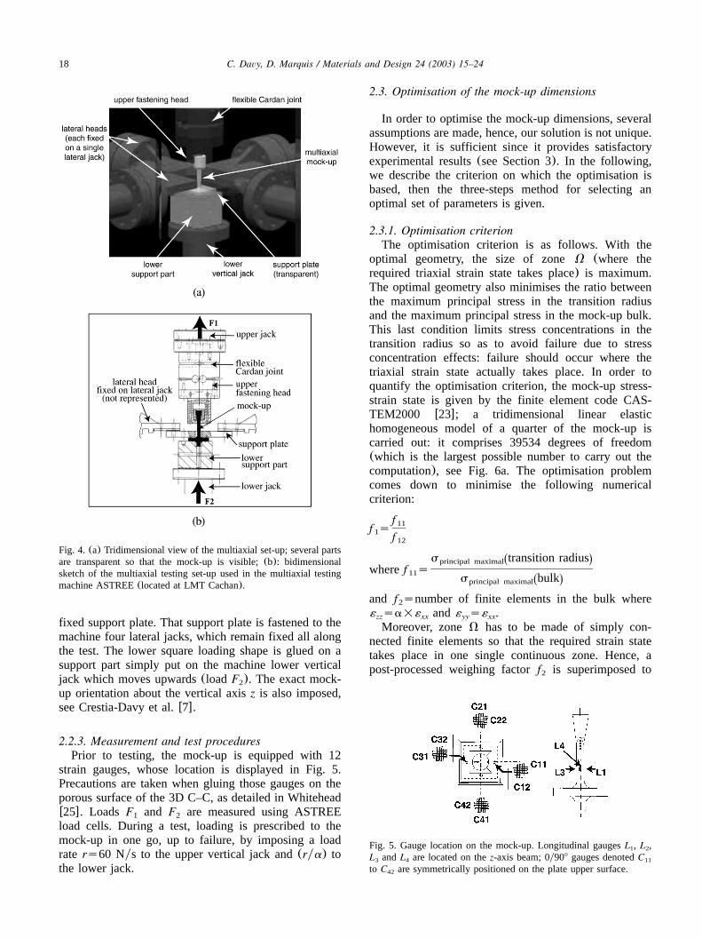
Fig. 4. (a) Tridimensional view of the multiaxial set-up; several partsare transparent so that the mock-up is visible;(b): bidimensionalsketch of the multiaxial testing set-up used in the multiaxial testingmachine ASTREE(located at LMT Cachan).
Fig. 5. Gauge location on the mock-up. Longitudinal gaugesL , L ,1 2
L andL are located on thez-axis beam; 0y908 gauges denotedC3 4 11
to C are symmetrically positioned on the plate upper surface.42
fixed support plate. That support plate is fastened to themachine four lateral jacks, which remain fixed all alongthe test. The lower square loading shape is glued on asupport part simply put on the machine lower verticaljack which moves upwards(loadF ). The exact mock-2
up orientation about the vertical axisz is also imposed,see Crestia-Davy et al.w7x.
2.2.3. Measurement and test proceduresPrior to testing, the mock-up is equipped with 12
strain gauges, whose location is displayed in Fig. 5.Precautions are taken when gluing those gauges on theporous surface of the 3D C–C, as detailed in Whiteheadw25x. Loads F and F are measured using ASTREE1 2
load cells. During a test, loading is prescribed to themock-up in one go, up to failure, by imposing a loadrate rs60 Nys to the upper vertical jack and(rya) tothe lower jack.
2.3. Optimisation of the mock-up dimensions
In order to optimise the mock-up dimensions, severalassumptions are made, hence, our solution is not unique.However, it is sufficient since it provides satisfactoryexperimental results(see Section 3). In the following,we describe the criterion on which the optimisation isbased, then the three-steps method for selecting anoptimal set of parameters is given.
2.3.1. Optimisation criterionThe optimisation criterion is as follows. With the
optimal geometry, the size of zoneV (where therequired triaxial strain state takes place) is maximum.The optimal geometry also minimises the ratio betweenthe maximum principal stress in the transition radiusand the maximum principal stress in the mock-up bulk.This last condition limits stress concentrations in thetransition radius so as to avoid failure due to stressconcentration effects: failure should occur where thetriaxial strain state actually takes place. In order toquantify the optimisation criterion, the mock-up stress-strain state is given by the finite element code CAS-TEM2000 w23x; a tridimensional linear elastichomogeneous model of a quarter of the mock-up iscarried out: it comprises 39534 degrees of freedom(which is the largest possible number to carry out thecomputation), see Fig. 6a. The optimisation problemcomes down to minimise the following numericalcriterion:
f11f s1 f12
s transition radiusŽ .principal maximalwheref s11
s bulkŽ .principal maximal
and f snumber of finite elements in the bulk where2
´ sa=´ and´ s´ .zz xx yy xx
Moreover, zoneV has to be made of simply con-nected finite elements so that the required strain statetakes place in one single continuous zone. Hence, apost-processed weighing factorf is superimposed to2
19C. Davy, D. Marquis / Materials and Design 24 (2003) 15–24
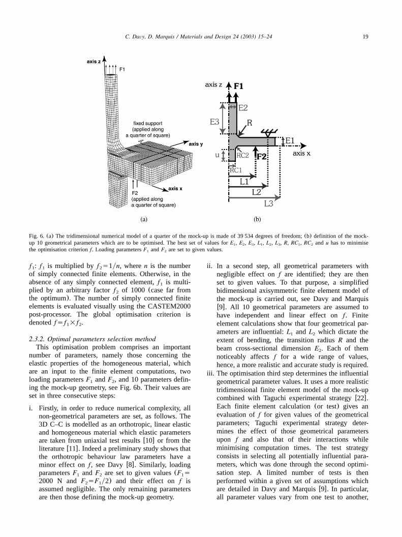
Fig. 6. (a) The tridimensional numerical model of a quarter of the mock-up is made of 39 534 degrees of freedom;(b) definition of the mock-up 10 geometrical parameters which are to be optimised. The best set of values forE , E , E , L , L , L , R, RC , RC and u has to minimise1 2 3 1 2 3 1 2
the optimisation criterionf. Loading parametersF andF are set to given values.1 2
f : f is multiplied by f s1yn, wheren is the number1 1 2
of simply connected finite elements. Otherwise, in theabsence of any simply connected element,f is multi-1
plied by an arbitrary factorf of 1000 (case far from2
the optimum). The number of simply connected finiteelements is evaluated visually using the CASTEM2000post-processor. The global optimisation criterion isdenotedfsf =f .1 2
2.3.2. Optimal parameters selection methodThis optimisation problem comprises an important
number of parameters, namely those concerning theelastic properties of the homogeneous material, whichare an input to the finite element computations, twoloading parametersF andF , and 10 parameters defin-1 2
ing the mock-up geometry, see Fig. 6b. Their values areset in three consecutive steps:
i. Firstly, in order to reduce numerical complexity, allnon-geometrical parameters are set, as follows. The3D C–C is modelled as an orthotropic, linear elasticand homogeneous material which elastic parametersare taken from uniaxial test resultsw10x or from theliteraturew11x. Indeed a preliminary study shows thatthe orthotropic behaviour law parameters have aminor effect on f, see Davyw8x. Similarly, loadingparametersF andF are set to given values(F s1 2 1
2000 N andF sF y2) and their effect onf is2 1
assumed negligible. The only remaining parametersare then those defining the mock-up geometry.
ii. In a second step, all geometrical parameters withnegligible effect onf are identified; they are thenset to given values. To that purpose, a simplifiedbidimensional axisymmetric finite element model ofthe mock-up is carried out, see Davy and Marquisw9x. All 10 geometrical parameters are assumed tohave independent and linear effect onf. Finiteelement calculations show that four geometrical par-ameters are influential:L and L which dictate the1 2
extent of bending, the transition radiusR and thebeam cross-sectional dimensionE . Each of them2
noticeably affectsf for a wide range of values,hence, a more realistic and accurate study is required.
iii. The optimisation third step determines the influentialgeometrical parameter values. It uses a more realistictridimensional finite element model of the mock-upcombined with Taguchi experimental strategyw22x.Each finite element calculation(or test) gives anevaluation of f for given values of the geometricalparameters; Taguchi experimental strategy deter-mines the effect of those geometrical parametersupon f and also that of their interactions whileminimising computation times. The test strategyconsists in selecting all potentially influential para-meters, which was done through the second optimi-sation step. A limited number of tests is thenperformed within a given set of assumptions whichare detailed in Davy and Marquisw9x. In particular,all parameter values vary from one test to another,
20 C. Davy, D. Marquis / Materials and Design 24 (2003) 15–24
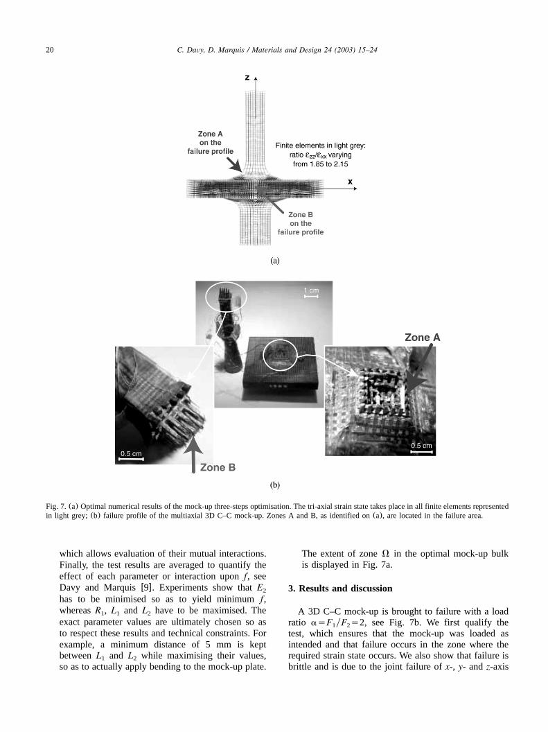
Fig. 7.(a) Optimal numerical results of the mock-up three-steps optimisation. The tri-axial strain state takes place in all finite elements representedin light grey; (b) failure profile of the multiaxial 3D C–C mock-up. Zones A and B, as identified on(a), are located in the failure area.
which allows evaluation of their mutual interactions.Finally, the test results are averaged to quantify theeffect of each parameter or interaction uponf, seeDavy and Marquisw9x. Experiments show thatE2
has to be minimised so as to yield minimumf,whereasR , L and L have to be maximised. The1 1 2
exact parameter values are ultimately chosen so asto respect these results and technical constraints. Forexample, a minimum distance of 5 mm is keptbetweenL and L while maximising their values,1 2
so as to actually apply bending to the mock-up plate.
The extent of zoneV in the optimal mock-up bulkis displayed in Fig. 7a.
3. Results and discussion
A 3D C–C mock-up is brought to failure with a loadratio asF yF s2, see Fig. 7b. We first qualify the1 2
test, which ensures that the mock-up was loaded asintended and that failure occurs in the zone where therequired strain state occurs. We also show that failure isbrittle and is due to the joint failure ofx-, y- andz-axis
21C. Davy, D. Marquis / Materials and Design 24 (2003) 15–24
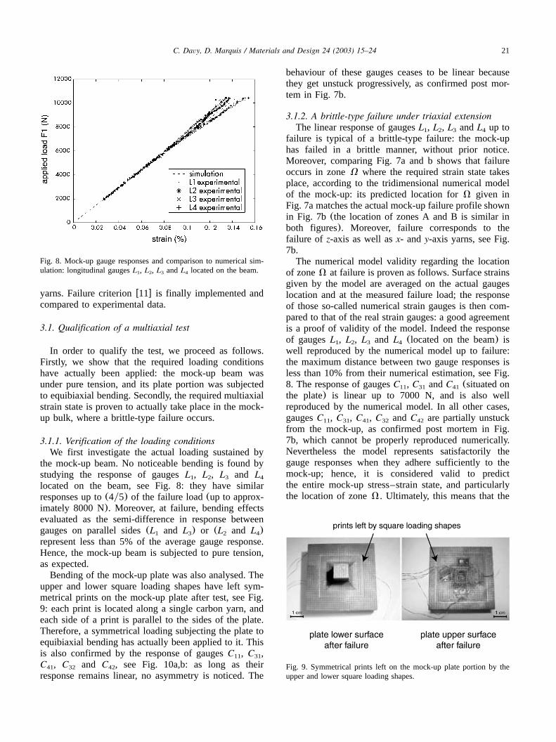
Fig. 8. Mock-up gauge responses and comparison to numerical sim-ulation: longitudinal gaugesL , L , L andL located on the beam.1 2 3 4
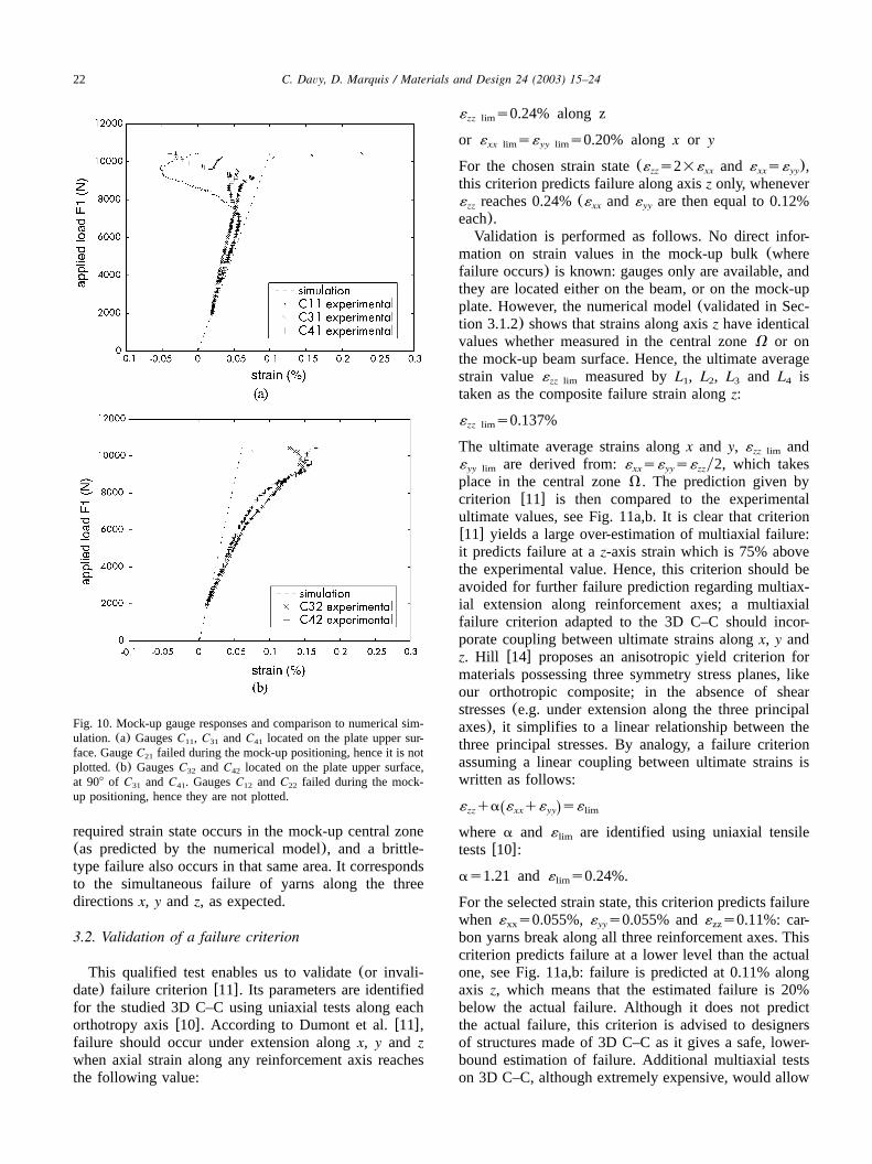
Fig. 9. Symmetrical prints left on the mock-up plate portion by theupper and lower square loading shapes.
yarns. Failure criterionw11x is finally implemented andcompared to experimental data.
3.1. Qualification of a multiaxial test
In order to qualify the test, we proceed as follows.Firstly, we show that the required loading conditionshave actually been applied: the mock-up beam wasunder pure tension, and its plate portion was subjectedto equibiaxial bending. Secondly, the required multiaxialstrain state is proven to actually take place in the mock-up bulk, where a brittle-type failure occurs.
3.1.1. Verification of the loading conditionsWe first investigate the actual loading sustained by
the mock-up beam. No noticeable bending is found bystudying the response of gaugesL , L , L and L1 2 3 4
located on the beam, see Fig. 8: they have similarresponses up to(4y5) of the failure load(up to approx-imately 8000 N). Moreover, at failure, bending effectsevaluated as the semi-difference in response betweengauges on parallel sides(L and L ) or (L and L )1 3 2 4
represent less than 5% of the average gauge response.Hence, the mock-up beam is subjected to pure tension,as expected.Bending of the mock-up plate was also analysed. The
upper and lower square loading shapes have left sym-metrical prints on the mock-up plate after test, see Fig.9: each print is located along a single carbon yarn, andeach side of a print is parallel to the sides of the plate.Therefore, a symmetrical loading subjecting the plate toequibiaxial bending has actually been applied to it. Thisis also confirmed by the response of gaugesC , C ,11 31
C , C and C , see Fig. 10a,b: as long as their41 32 42
response remains linear, no asymmetry is noticed. The
behaviour of these gauges ceases to be linear becausethey get unstuck progressively, as confirmed post mor-tem in Fig. 7b.
3.1.2. A brittle-type failure under triaxial extensionThe linear response of gaugesL , L , L andL up to1 2 3 4
failure is typical of a brittle-type failure: the mock-uphas failed in a brittle manner, without prior notice.Moreover, comparing Fig. 7a and b shows that failureoccurs in zoneV where the required strain state takesplace, according to the tridimensional numerical modelof the mock-up: its predicted location forV given inFig. 7a matches the actual mock-up failure profile shownin Fig. 7b (the location of zones A and B is similar inboth figures). Moreover, failure corresponds to thefailure of z-axis as well asx- andy-axis yarns, see Fig.7b.The numerical model validity regarding the location
of zoneV at failure is proven as follows. Surface strainsgiven by the model are averaged on the actual gaugeslocation and at the measured failure load; the responseof those so-called numerical strain gauges is then com-pared to that of the real strain gauges: a good agreementis a proof of validity of the model. Indeed the responseof gaugesL , L , L and L (located on the beam) is1 2 3 4
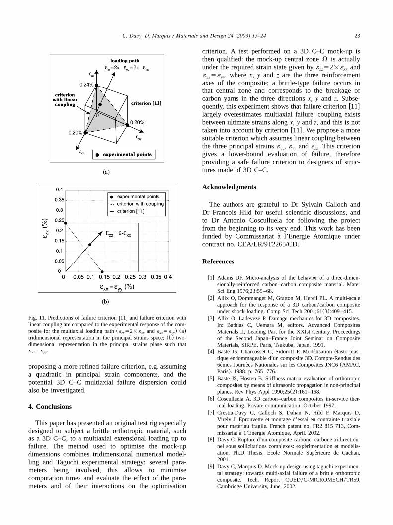
well reproduced by the numerical model up to failure:the maximum distance between two gauge responses isless than 10% from their numerical estimation, see Fig.8. The response of gaugesC , C andC (situated on11 31 41
the plate) is linear up to 7000 N, and is also wellreproduced by the numerical model. In all other cases,gaugesC , C , C , C andC are partially unstuck11 31 41 32 42
from the mock-up, as confirmed post mortem in Fig.7b, which cannot be properly reproduced numerically.Nevertheless the model represents satisfactorily thegauge responses when they adhere sufficiently to themock-up; hence, it is considered valid to predictthe entire mock-up stress–strain state, and particularlythe location of zoneV. Ultimately, this means that the
22 C. Davy, D. Marquis / Materials and Design 24 (2003) 15–24
Fig. 10. Mock-up gauge responses and comparison to numerical sim-ulation. (a) GaugesC , C andC located on the plate upper sur-11 31 41
face. GaugeC failed during the mock-up positioning, hence it is not21
plotted. (b) GaugesC andC located on the plate upper surface,32 42
at 908 of C andC . GaugesC andC failed during the mock-31 41 12 22
up positioning, hence they are not plotted.
required strain state occurs in the mock-up central zone(as predicted by the numerical model), and a brittle-type failure also occurs in that same area. It correspondsto the simultaneous failure of yarns along the threedirectionsx, y and z, as expected.
3.2. Validation of a failure criterion
This qualified test enables us to validate(or invali-date) failure criterionw11x. Its parameters are identifiedfor the studied 3D C–C using uniaxial tests along eachorthotropy axisw10x. According to Dumont et al.w11x,failure should occur under extension alongx, y and zwhen axial strain along any reinforcement axis reachesthe following value:
´ s0.24% along zzz lim
or ´ s´ s0.20% alongx or yxx lim yy lim
For the chosen strain state(´ s2=´ and ´ s´ ),zz xx xx yy
this criterion predicts failure along axisz only, whenever´ reaches 0.24%(´ and´ are then equal to 0.12%zz xx yy
each).Validation is performed as follows. No direct infor-
mation on strain values in the mock-up bulk(wherefailure occurs) is known: gauges only are available, andthey are located either on the beam, or on the mock-upplate. However, the numerical model(validated in Sec-tion 3.1.2) shows that strains along axisz have identicalvalues whether measured in the central zoneV or onthe mock-up beam surface. Hence, the ultimate averagestrain value´ measured byL , L , L and L iszz lim 1 2 3 4
taken as the composite failure strain alongz:
´ s0.137%zz lim
The ultimate average strains alongx and y, ´ andzz lim
´ are derived from: s´ s´ y2, which takesyy lim xx yy zz
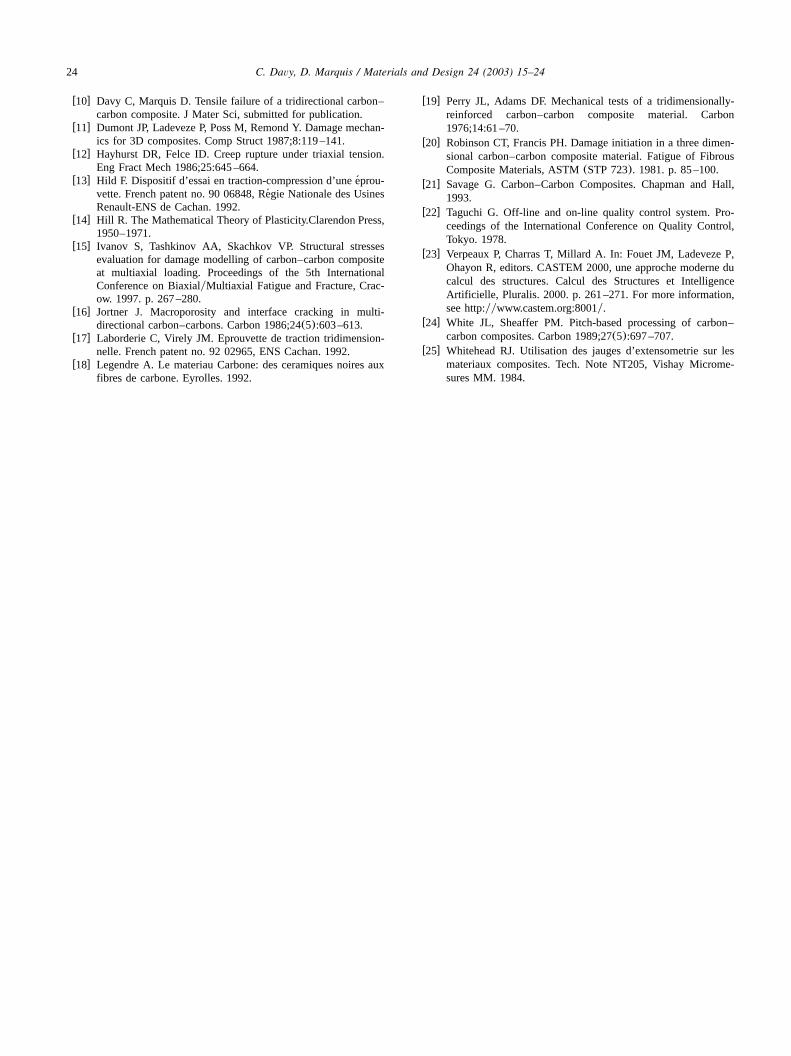
place in the central zoneV. The prediction given bycriterion w11x is then compared to the experimentalultimate values, see Fig. 11a,b. It is clear that criterionw11x yields a large over-estimation of multiaxial failure:it predicts failure at az-axis strain which is 75% abovethe experimental value. Hence, this criterion should beavoided for further failure prediction regarding multiax-ial extension along reinforcement axes; a multiaxialfailure criterion adapted to the 3D C–C should incor-porate coupling between ultimate strains alongx, y andz. Hill w14x proposes an anisotropic yield criterion formaterials possessing three symmetry stress planes, likeour orthotropic composite; in the absence of shearstresses(e.g. under extension along the three principalaxes), it simplifies to a linear relationship between thethree principal stresses. By analogy, a failure criterionassuming a linear coupling between ultimate strains iswritten as follows:
´ qa ´ q´ s´Ž .zz xx yy lim
where a and ´ are identified using uniaxial tensilelim
testsw10x:
as1.21 and´ s0.24%.lim
For the selected strain state, this criterion predicts failurewhen ´ s0.055%,´ s0.055% and s0.11%: car-xx yy zz
bon yarns break along all three reinforcement axes. Thiscriterion predicts failure at a lower level than the actualone, see Fig. 11a,b: failure is predicted at 0.11% alongaxis z, which means that the estimated failure is 20%below the actual failure. Although it does not predictthe actual failure, this criterion is advised to designersof structures made of 3D C–C as it gives a safe, lower-bound estimation of failure. Additional multiaxial testson 3D C–C, although extremely expensive, would allow
23C. Davy, D. Marquis / Materials and Design 24 (2003) 15–24
Fig. 11. Predictions of failure criterionw11x and failure criterion withlinear coupling are compared to the experimental response of the com-posite for the multiaxial loading path(´ s2=´ and´ s´ ) (a)zz xx xx yy
tridimensional representation in the principal strains space;(b) two-dimensional representation in the principal strains plane such that´ s´ .xx yy
proposing a more refined failure criterion, e.g. assuminga quadratic in principal strain components, and thepotential 3D C–C multiaxial failure dispersion couldalso be investigated.
4. Conclusions
This paper has presented an original test rig especiallydesigned to subject a brittle orthotropic material, suchas a 3D C–C, to a multiaxial extensional loading up tofailure. The method used to optimise the mock-updimensions combines tridimensional numerical model-ling and Taguchi experimental strategy; several para-meters being involved, this allows to minimisecomputation times and evaluate the effect of the para-meters and of their interactions on the optimisation
criterion. A test performed on a 3D C–C mock-up isthen qualified: the mock-up central zoneV is actuallyunder the required strain state given by´ s2=´ andzz xx
´ s´ , wherex, y and z are the three reinforcementxx yy
axes of the composite; a brittle-type failure occurs inthat central zone and corresponds to the breakage ofcarbon yarns in the three directionsx, y and z. Subse-quently, this experiment shows that failure criterionw11xlargely overestimates multiaxial failure: coupling existsbetween ultimate strains alongx, y andz, and this is nottaken into account by criterionw11x. We propose a moresuitable criterion which assumes linear coupling betweenthe three principal strains , ´ and´ . This criterionxx yy zz
gives a lower-bound evaluation of failure, thereforeproviding a safe failure criterion to designers of struc-tures made of 3D C–C.
Acknowledgments
The authors are grateful to Dr Sylvain Calloch andDr Francois Hild for useful scientific discussions, andto Dr Antonio Cosculluela for following the projectfrom the beginning to its very end. This work has beenfunded by Commissariat a l’Energie Atomique under`contract no. CEA/LR/9T2265/CD.
References
w1x Adams DF. Micro-analysis of the behavior of a three-dimen-sionally-reinforced carbon–carbon composite material. MaterSci Eng 1976;23:55–68.
w2x Allix O, Dommanget M, Gratton M, Hereil PL. A multi-scaleapproach for the response of a 3D carbonycarbon compositeunder shock loading. Comp Sci Tech 2001;61(3):409–415.
w3x Allix O, Ladeveze P. Damage mechanics for 3D composites.In: Bathias C, Uemara M, editors. Advanced CompositesMaterials II, Leading Part for the XXIst Century, Proceedingsof the Second Japan–France Joint Seminar on CompositeMaterials, SIRPE, Paris, Tsukuba, Japan. 1991.
w4x Baste JS, Charcosset C, Sidoroff F. Modelisation elasto-plas-´ ´tique endommageable d’un composite 3D. Compte-Rendus des6emes Journees Nationales sur les Composites JNC6(AMAC,` ´Paris). 1988. p. 765–776.
w5x Baste JS, Hosten B. Stiffness matrix evaluation of orthotropiccomposites by means of ultrasonic propagation in non-principalplanes. Rev Phys Appl 1990;25(2):161–168.
w6x Cosculluela A. 3D carbon–carbon composites in-service ther-mal loading. Private communication, October 1997.
w7x Crestia-Davy C, Calloch S, Dahan N, Hild F, Marquis D,Virely J. Eprouvette et montage d’essai en contrainte triaxialepour materiau fragile. French patent no. FR2 815 713, Com-´missariat a 1’Energie Atomique, April. 2002.`
w8x Davy C. Rupture d’un composite carbone–carbone tridirection-nel sous sollicitations complexes: experimentation et modelis-´ ´ation. Ph.D Thesis, Ecole Normale Superieure de Cachan,´2001.
w9x Davy C, Marquis D. Mock-up design using taguchi experimen-tal strategy: towards multi-axial failure of a brittle orthotropiccomposite. Tech. Report CUEDyC-MICROMECHyTR59,Cambridge University, June. 2002.
24 C. Davy, D. Marquis / Materials and Design 24 (2003) 15–24
w10x Davy C, Marquis D. Tensile failure of a tridirectional carbon–carbon composite. J Mater Sci, submitted for publication.
w11x Dumont JP, Ladeveze P, Poss M, Remond Y. Damage mechan-ics for 3D composites. Comp Struct 1987;8:119–141.
w12x Hayhurst DR, Felce ID. Creep rupture under triaxial tension.Eng Fract Mech 1986;25:645–664.
w13x Hild F. Dispositif d’essai en traction-compression d’une eprou-´vette. French patent no. 90 06848, Regie Nationale des Usines´Renault-ENS de Cachan. 1992.
w14x Hill R. The Mathematical Theory of Plasticity.Clarendon Press,1950–1971.
w15x Ivanov S, Tashkinov AA, Skachkov VP. Structural stressesevaluation for damage modelling of carbon–carbon compositeat multiaxial loading. Proceedings of the 5th InternationalConference on BiaxialyMultiaxial Fatigue and Fracture, Crac-ow. 1997. p. 267–280.
w16x Jortner J. Macroporosity and interface cracking in multi-directional carbon–carbons. Carbon 1986;24(5):603–613.
w17x Laborderie C, Virely JM. Eprouvette de traction tridimension-nelle. French patent no. 92 02965, ENS Cachan. 1992.
w18x Legendre A. Le materiau Carbone: des ceramiques noires auxfibres de carbone. Eyrolles. 1992.
w19x Perry JL, Adams DF. Mechanical tests of a tridimensionally-reinforced carbon–carbon composite material. Carbon1976;14:61–70.
w20x Robinson CT, Francis PH. Damage initiation in a three dimen-sional carbon–carbon composite material. Fatigue of FibrousComposite Materials, ASTM(STP 723). 1981. p. 85–100.
w21x Savage G. Carbon–Carbon Composites. Chapman and Hall,1993.
w22x Taguchi G. Off-line and on-line quality control system. Pro-ceedings of the International Conference on Quality Control,Tokyo. 1978.
w23x Verpeaux P, Charras T, Millard A. In: Fouet JM, Ladeveze P,Ohayon R, editors. CASTEM 2000, une approche moderne ducalcul des structures. Calcul des Structures et IntelligenceArtificielle, Pluralis. 2000. p. 261–271. For more information,see http:yywww.castem.org:8001y.
w24x White JL, Sheaffer PM. Pitch-based processing of carbon–carbon composites. Carbon 1989;27(5):697–707.
w25x Whitehead RJ. Utilisation des jauges d’extensometrie sur lesmateriaux composites. Tech. Note NT205, Vishay Microme-sures MM. 1984.