Embed Size (px)
Citation preview
International Research Journal of Engineering and Technology (IRJET) e-ISSN: 2395 -0056
Volume: 03 Issue: 06 | June-2016 www.irjet.net p-ISSN: 2395-0072
© 2016, IRJET | Impact Factor value: 4.45 | ISO 9001:2008 Certified Journal | Page 380
A Multi Input DC-DC Converter for Renewable Energy Applications
J. Sai Kumar1, Tikeshwar Gajpal2
1ME Student, Department of EEE, Raipur Institute of Technology, 2Assistant Professor, Department of EEE, Raipur Institute of Technology.
---------------------------------------------------------------------***---------------------------------------------------------------------
Abstract - This paper puts forward, power management of different types of renewable energy sources whose voltages and currents are tracked by the Maximum power point tracking (MPPT) controller. In this, boost converter has been used as a multiport DC-DC converter to which each of the port is connected with controller switch to control the source input of converter. Four ports has been used of which two are the PV panels and the remaining two are the remaining two are the wind turbine generators (WTGs). Since, less number of switches has been used in the proposed converter which reduces the switching losses in the converter. The diode bridge rectifier is relevant for high switching frequency operation with achievable component relating with conventional converter. The converter is designed and simulated through MATLAB software. As an application part an induction motor has been interfaced at the load whose speed and electromagnetic torque has been measured and shown in the form of waveforms. The proposed converter has reliability operate instantaneous power generation from different renewable energy sources. The output of the MPPT controller is the duty cycle which is regularly updated to track the maximum power from the energy sources and this duty cycle switches on the corresponding switch of the boost converter.
Key Words: solar energy, wind energy, multiport dc-dc converter, maximum power point tracking (MPPT), power management.
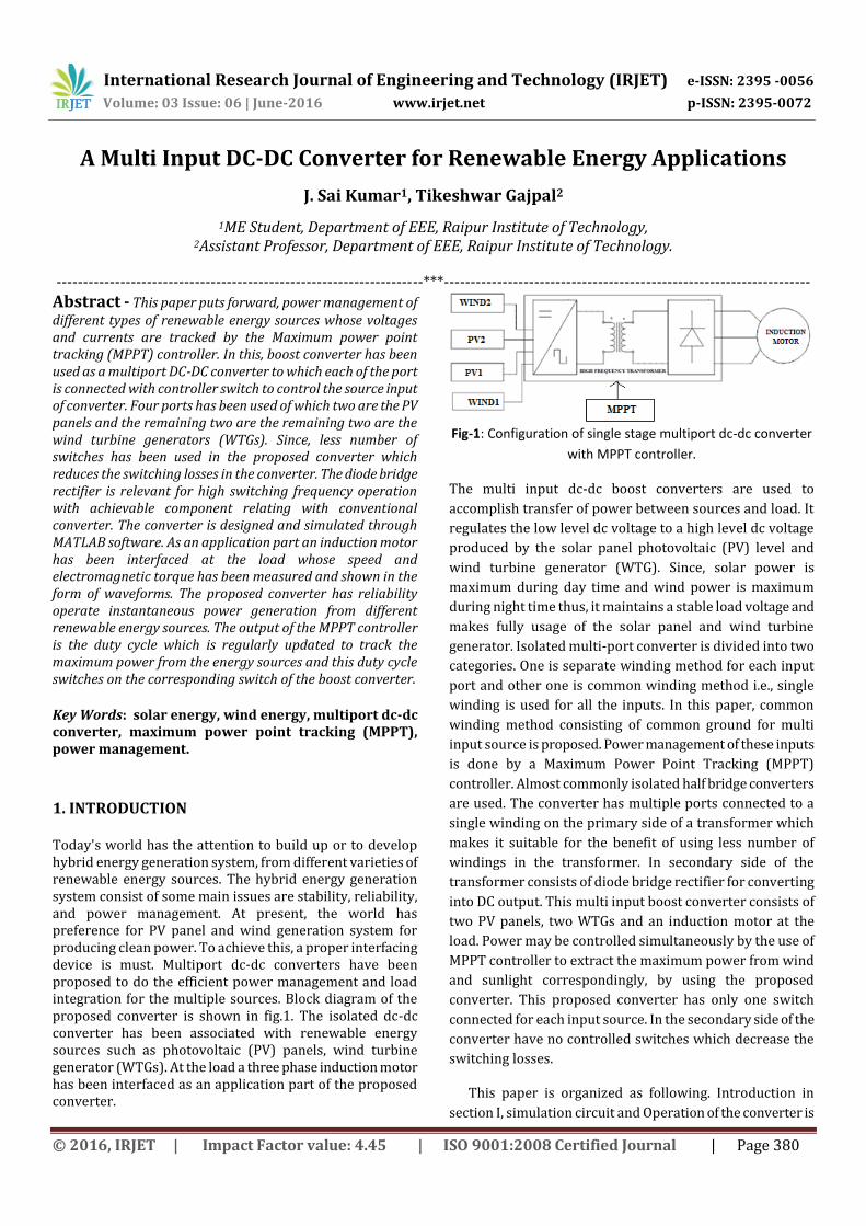
1. INTRODUCTION Today's world has the attention to build up or to develop hybrid energy generation system, from different varieties of renewable energy sources. The hybrid energy generation system consist of some main issues are stability, reliability, and power management. At present, the world has preference for PV panel and wind generation system for producing clean power. To achieve this, a proper interfacing device is must. Multiport dc-dc converters have been proposed to do the efficient power management and load integration for the multiple sources. Block diagram of the proposed converter is shown in fig.1. The isolated dc-dc converter has been associated with renewable energy sources such as photovoltaic (PV) panels, wind turbine generator (WTGs). At the load a three phase induction motor has been interfaced as an application part of the proposed converter.
Fig-1: Configuration of single stage multiport dc-dc converter
with MPPT controller.
The multi input dc-dc boost converters are used to
accomplish transfer of power between sources and load. It
regulates the low level dc voltage to a high level dc voltage
produced by the solar panel photovoltaic (PV) level and
wind turbine generator (WTG). Since, solar power is
maximum during day time and wind power is maximum
during night time thus, it maintains a stable load voltage and
makes fully usage of the solar panel and wind turbine
generator. Isolated multi-port converter is divided into two
categories. One is separate winding method for each input
port and other one is common winding method i.e., single
winding is used for all the inputs. In this paper, common
winding method consisting of common ground for multi
input source is proposed. Power management of these inputs
is done by a Maximum Power Point Tracking (MPPT)
controller. Almost commonly isolated half bridge converters
are used. The converter has multiple ports connected to a
single winding on the primary side of a transformer which
makes it suitable for the benefit of using less number of
windings in the transformer. In secondary side of the
transformer consists of diode bridge rectifier for converting
into DC output. This multi input boost converter consists of
two PV panels, two WTGs and an induction motor at the
load. Power may be controlled simultaneously by the use of
MPPT controller to extract the maximum power from wind
and sunlight correspondingly, by using the proposed
converter. This proposed converter has only one switch
connected for each input source. In the secondary side of the
converter have no controlled switches which decrease the
switching losses.
This paper is organized as following. Introduction in
section I, simulation circuit and Operation of the converter is
International Research Journal of Engineering and Technology (IRJET) e-ISSN: 2395 -0056
Volume: 03 Issue: 06 | June-2016 www.irjet.net p-ISSN: 2395-0072
© 2016, IRJET | Impact Factor value: 4.45 | ISO 9001:2008 Certified Journal | Page 381
discussed in the section II. In Section III MPPT controller and
H/VZ control of induction motor is discussed. Modeling of
solar panel and WTG are discussed in section IV and section
V Results and discussions are given in Section VI and finally
conclusion is given in section VII.
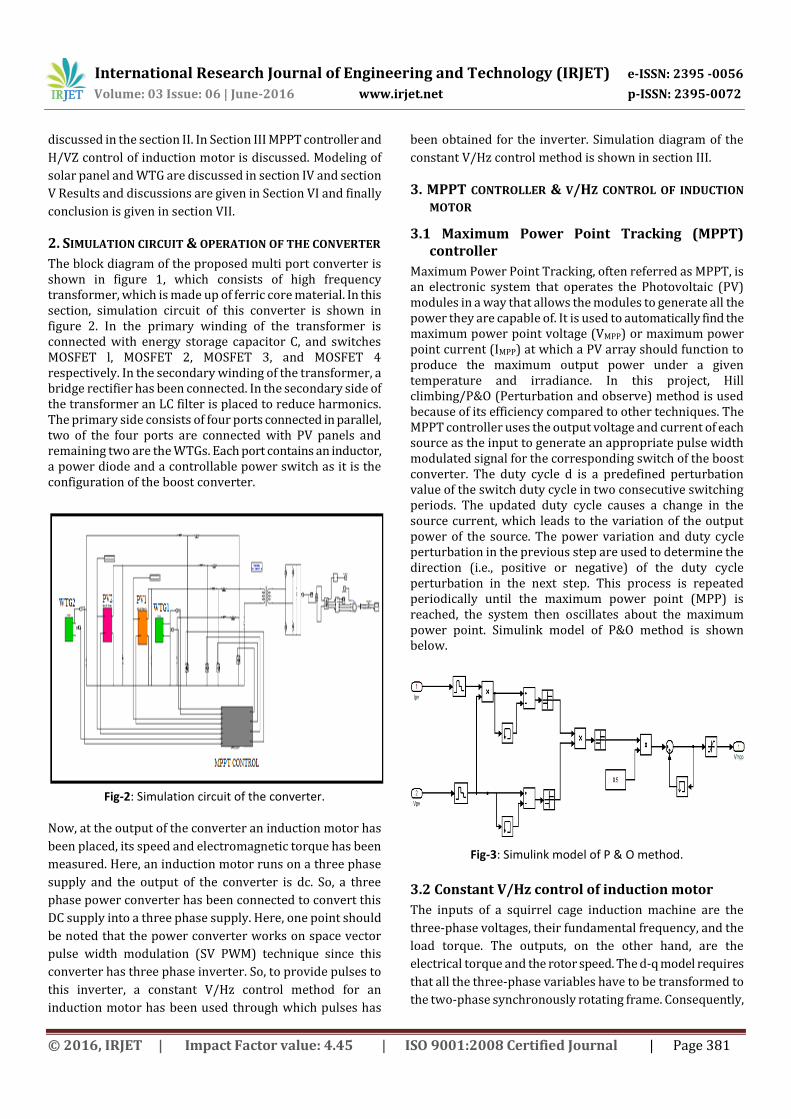
2. SIMULATION CIRCUIT & OPERATION OF THE CONVERTER
The block diagram of the proposed multi port converter is shown in figure 1, which consists of high frequency transformer, which is made up of ferric core material. In this section, simulation circuit of this converter is shown in figure 2. In the primary winding of the transformer is connected with energy storage capacitor C, and switches MOSFET l, MOSFET 2, MOSFET 3, and MOSFET 4 respectively. In the secondary winding of the transformer, a bridge rectifier has been connected. In the secondary side of the transformer an LC filter is placed to reduce harmonics. The primary side consists of four ports connected in parallel, two of the four ports are connected with PV panels and remaining two are the WTGs. Each port contains an inductor, a power diode and a controllable power switch as it is the configuration of the boost converter.
Fig-2: Simulation circuit of the converter.
Now, at the output of the converter an induction motor has
been placed, its speed and electromagnetic torque has been
measured. Here, an induction motor runs on a three phase
supply and the output of the converter is dc. So, a three
phase power converter has been connected to convert this
DC supply into a three phase supply. Here, one point should
be noted that the power converter works on space vector
pulse width modulation (SV PWM) technique since this
converter has three phase inverter. So, to provide pulses to
this inverter, a constant V/Hz control method for an
induction motor has been used through which pulses has
been obtained for the inverter. Simulation diagram of the
constant V/Hz control method is shown in section III.
3. MPPT CONTROLLER & V/HZ CONTROL OF INDUCTION
MOTOR
3.1 Maximum Power Point Tracking (MPPT) controller
Maximum Power Point Tracking, often referred as MPPT, is an electronic system that operates the Photovoltaic (PV) modules in a way that allows the modules to generate all the power they are capable of. It is used to automatically find the maximum power point voltage (VMPP) or maximum power point current (IMPP) at which a PV array should function to produce the maximum output power under a given temperature and irradiance. In this project, Hill climbing/P&O (Perturbation and observe) method is used because of its efficiency compared to other techniques. The MPPT controller uses the output voltage and current of each source as the input to generate an appropriate pulse width modulated signal for the corresponding switch of the boost converter. The duty cycle d is a predefined perturbation value of the switch duty cycle in two consecutive switching periods. The updated duty cycle causes a change in the source current, which leads to the variation of the output power of the source. The power variation and duty cycle perturbation in the previous step are used to determine the direction (i.e., positive or negative) of the duty cycle perturbation in the next step. This process is repeated periodically until the maximum power point (MPP) is reached, the system then oscillates about the maximum power point. Simulink model of P&O method is shown below.
Fig-3: Simulink model of P & O method.
3.2 Constant V/Hz control of induction motor
The inputs of a squirrel cage induction machine are the
three-phase voltages, their fundamental frequency, and the
load torque. The outputs, on the other hand, are the
electrical torque and the rotor speed. The d-q model requires
that all the three-phase variables have to be transformed to
the two-phase synchronously rotating frame. Consequently,
International Research Journal of Engineering and Technology (IRJET) e-ISSN: 2395 -0056
Volume: 03 Issue: 06 | June-2016 www.irjet.net p-ISSN: 2395-0072
© 2016, IRJET | Impact Factor value: 4.45 | ISO 9001:2008 Certified Journal | Page 382
the induction machine model will have blocks transforming
the three-phase voltages back to three-phase.
Figure 4 shows the implementation of open-loop constant
V/Hz control of an induction machine.
Fig -4: Constant V/Hz control. An assumed RPM of 500 is given to the saturation block, which limits input signal to the upper and lower saturation values. From the gain block it is given to the discrete time integrator from where space angle theta is calculated. Look up table is used to find the Switching patterns and output voltages or space vectors for a 3-phase power inverter. The output of this controller is given to the discrete space vector pulse width modulation (SV PWM) which generates pulses for a three-phase basic two-level voltage-sourced converter (VSC) consisting of three half-bridge switching devices (FETs, GTOs or IGBTs). The block utilizes the space vector pulse width modulation (SV PWM) technique to generate firing pulses to the 6 switching devices of the converter. This in turn generates three phase voltages for induction motor.
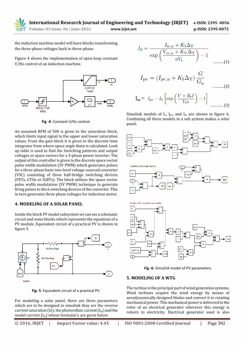
4. MODELING OF A SOLAR PANEL Inside the block PV model subsystem we can see a schematic circuit and some blocks which represents the equations of a PV module. Equivalent circuit of a practical PV is shown in figure 5.
Fig- 5: Equivalent circuit of a practical PV.
For modeling a solar panel, there are three parameters which are to be designed in simulink they are the reverse current saturation (Io), the photovoltaic current (Ipv) and the model current (Im) whose formulae’s are given below.
………..(1)
………...(2)
………… (3)
Simulink models of Io, Ipv, and Im are shown in figure 6. Combining all three models in a sub system makes a solar panel.
Fig -6: Simulink model of PV parameters. 5. MODELING OF A WTG The turbine is the principal part of wind generation systems. Wind turbines acquire the wind energy by means of aerodynamically designed blades and convert it to rotating mechanical power. This mechanical power is delivered to the rotor of an electrical generator wherever this energy is reborn to electricity. Electrical generator used is also
International Research Journal of Engineering and Technology (IRJET) e-ISSN: 2395 -0056
Volume: 03 Issue: 06 | June-2016 www.irjet.net p-ISSN: 2395-0072
© 2016, IRJET | Impact Factor value: 4.45 | ISO 9001:2008 Certified Journal | Page 383
associate degree induction generator or synchronous generator. The mechanical power that is generated by the wind is given by:
Where, ρ - Air density, A - Rotor swept area, Cp (λ, β) - power coefficient function, λ - Tip speed ratio, β - Pitch angle, VW -wind speed
Simulink model of a wind turbine generator is shown in figure 7 in which the output voltage from the wind block is given to the capacitor bank circuit. This capacitor bank compensates the fluctuations present in the output of the wind block because the wind energy is not constant due to this large fluctuations are occurred. A step up transformer has been used to enlarge the voltage produced by the wind. And the voltage and current has been measured by a three phase VI measurement block. A rectifier block with snubber circuit has been used which is used to suppress or snub the voltage transients which leads to a sharp rise in voltage in accordance with faradays law.
Fig-7: Simulink model of a WTG
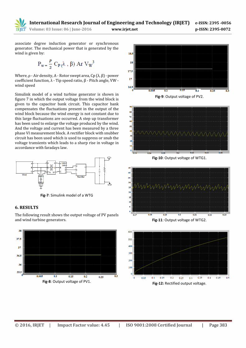
6. RESULTS
The following result shows the output voltage of PV panels and wind turbine generators.
Fig-8: Output voltage of PV1.
Fig-9: Output voltage of PV2.
Fig-10: Output voltage of WTG1.
Fig-11: Output voltage of WTG2.
Fig-12: Rectified output voltage.
International Research Journal of Engineering and Technology (IRJET) e-ISSN: 2395 -0056
Volume: 03 Issue: 06 | June-2016 www.irjet.net p-ISSN: 2395-0072
© 2016, IRJET | Impact Factor value: 4.45 | ISO 9001:2008 Certified Journal | Page 384
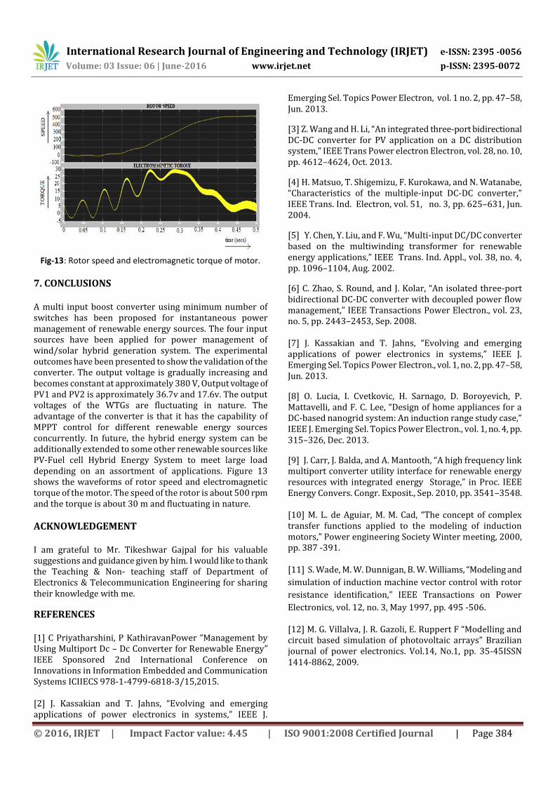
Fig-13: Rotor speed and electromagnetic torque of motor.
7. CONCLUSIONS A multi input boost converter using minimum number of switches has been proposed for instantaneous power management of renewable energy sources. The four input sources have been applied for power management of wind/solar hybrid generation system. The experimental outcomes have been presented to show the validation of the converter. The output voltage is gradually increasing and becomes constant at approximately 380 V, Output voltage of PV1 and PV2 is approximately 36.7v and 17.6v. The output voltages of the WTGs are fluctuating in nature. The advantage of the converter is that it has the capability of MPPT control for different renewable energy sources concurrently. In future, the hybrid energy system can be additionally extended to some other renewable sources like PV-Fuel cell Hybrid Energy System to meet large load depending on an assortment of applications. Figure 13 shows the waveforms of rotor speed and electromagnetic torque of the motor. The speed of the rotor is about 500 rpm and the torque is about 30 m and fluctuating in nature.
ACKNOWLEDGEMENT I am grateful to Mr. Tikeshwar Gajpal for his valuable suggestions and guidance given by him. I would like to thank the Teaching & Non- teaching staff of Department of Electronics & Telecommunication Engineering for sharing their knowledge with me.
REFERENCES [1] C Priyatharshini, P KathiravanPower “Management by Using Multiport Dc – Dc Converter for Renewable Energy” IEEE Sponsored 2nd International Conference on Innovations in Information Embedded and Communication Systems ICIIECS 978-1-4799-6818-3/15,2015. [2] J. Kassakian and T. Jahns, “Evolving and emerging applications of power electronics in systems,” IEEE J.
Emerging Sel. Topics Power Electron, vol. 1 no. 2, pp. 47–58, Jun. 2013.
[3] Z. Wang and H. Li, “An integrated three-port bidirectional DC-DC converter for PV application on a DC distribution system,” IEEE Trans Power electron Electron, vol. 28, no. 10, pp. 4612–4624, Oct. 2013.
[4] H. Matsuo, T. Shigemizu, F. Kurokawa, and N. Watanabe, “Characteristics of the multiple-input DC-DC converter,” IEEE Trans. Ind. Electron, vol. 51, no. 3, pp. 625–631, Jun. 2004.
[5] Y. Chen, Y. Liu, and F. Wu, “Multi-input DC/DC converter based on the multiwinding transformer for renewable energy applications,” IEEE Trans. Ind. Appl., vol. 38, no. 4, pp. 1096–1104, Aug. 2002.
[6] C. Zhao, S. Round, and J. Kolar, “An isolated three-port bidirectional DC-DC converter with decoupled power flow management,” IEEE Transactions Power Electron., vol. 23, no. 5, pp. 2443–2453, Sep. 2008. [7] J. Kassakian and T. Jahns, “Evolving and emerging applications of power electronics in systems,” IEEE J. Emerging Sel. Topics Power Electron., vol. 1, no. 2, pp. 47–58, Jun. 2013.
[8] O. Lucia, I. Cvetkovic, H. Sarnago, D. Boroyevich, P. Mattavelli, and F. C. Lee, “Design of home appliances for a DC-based nanogrid system: An induction range study case,” IEEE J. Emerging Sel. Topics Power Electron., vol. 1, no. 4, pp. 315–326, Dec. 2013.
[9] J. Carr, J. Balda, and A. Mantooth, “A high frequency link multiport converter utility interface for renewable energy resources with integrated energy Storage,” in Proc. IEEE Energy Convers. Congr. Exposit., Sep. 2010, pp. 3541–3548. [10] M. L. de Aguiar, M. M. Cad, “The concept of complex transfer functions applied to the modeling of induction motors,” Power engineering Society Winter meeting, 2000, pp. 387 -391. [11] S. Wade, M. W. Dunnigan, B. W. Williams, “Modeling and
simulation of induction machine vector control with rotor
resistance identification,” IEEE Transactions on Power
Electronics, vol. 12, no. 3, May 1997, pp. 495 -506.
[12] M. G. Villalva, J. R. Gazoli, E. Ruppert F “Modelling and circuit based simulation of photovoltaic arrays” Brazilian journal of power electronics. Vol.14, No.1, pp. 35-45ISSN 1414-8862, 2009.
![Multi-Stage DC-AC Converter Based on New DC-DC Converter ...joape.uma.ac.ir/article_427_07fce5c1eaa8adada9b3e62c076eeee0.pdfdiodes in one phase. In Ref. [19] the hybrid seven-level](https://img.pdfslide.us/doc/110x75/5f4b8b47cfec67592c2cce47/multi-stage-dc-ac-converter-based-on-new-dc-dc-converter-joapeumaacirarticle42707fce5c1eaa8.jpg)