Embed Size (px)
Citation preview

1530-437X (c) 2021 IEEE. Personal use is permitted, but republication/redistribution requires IEEE permission. See http://www.ieee.org/publications_standards/publications/rights/index.html for more information.
This article has been accepted for publication in a future issue of this journal, but has not been fully edited. Content may change prior to final publication. Citation information: DOI 10.1109/JSEN.2021.3058354, IEEE SensorsJournal
IEEE SENSORS JOURNAL, VOL. XX, NO. XX, MONTH X, XXXX 1
XXXX-XXXX © XXXX IEEE. Personal use is permitted, but republication/redistribution requires IEEE permission.
See http://www.ieee.org/publications_standards/publications/rights/index.html for more information.
Abstract—This paper proposes a main-functional module working concept for capsule robots, and the capsule robots consist of a main module and functional modules based on this concept. The main module drives the functional modules and provides guidance and support for the functional modules while the functional modules perform the specific diagnosis or treatment. In addition, we propose a novel single-function design concept, which enables different functional modules to have different functions according to the medical requirements. The diagnosis and treatment functions are separated, and they will allow each module to work more specifically and efficiently. Various functional modules can be selected according to medical requirements, and thus it can improve treatment efficiency and reduce medical costs. The single-function design concept eliminates the need to integrate multiple functions into one robot and decrease manufacturing difficulty. Besides, we present a novel docking-separation method to realize effective docking and rapid separation for capsule robots. It can also enable the docked robot to work in bent parts of intestinal tracts easily. A multimodule capsule robot (MCR) was fabricated and the performance was evaluated through experiments. Experimental results demonstrated that the robot modules could be controlled independently and could dock reliably and separate easily. Moreover, the MCR can prevent accidental separation and has potential applications in the clinical practices of intestinal tracts.
Index Terms—Capsule robot, intestinal endoscopy, main-functional module, magnetic navigation.
I. Introduction
NTESTINAL cancer becomes one of the most common
cancers and causes of cancer-associated deaths [1].
Earlier-stage diagnosis and treatments for intestinal diseases
can reduce the difficulty of the operation and decrease the
fatality rate [2]. Intestinal endoscopy, which uses a long
flexible tube with a light and camera to insert from the mouth or
anus to the nidus, is used to perform diagnosis and treatments.
However, conventional intestinal endoscopy has caused
discomfort and pain to patients and some potential
complications in the process of operation, which may include
perforation, infection, bleeding, and so on. In addition, the
success rate mainly depends on the experience of surgeons.
Therefore, microrobot has been widely investigated due to its
potential applications in the clinical practices of intestinal
tracts.
M. Sitti et al. proposed a capsule robot controlled by a
Manuscript received Decmber 13, 2020; revised January 16, 2021;
accepted January 28, 2021. This work was supported in part by the National High-Tech Research
and Development Program (863 Program) of China under Grant 2015AA043202, and in part by SPS KAKENHI under Grant 15K2120. (Corresponding author: Shuxiang Guo)
L. Zheng, S. Guo, and Z. Wang are with the Graduate School of Engineering, Kagawa University, Takamatsu 761-0396, Japan (e-mail: [email protected]; [email protected];
[email protected]; [email protected]). S. Guo is also with the Key Laboratory of Convergence Medical
Engineering System and Healthcare Technology, Ministry of Industry
and Information Technology, Beijing Institute of Technology, Beijing 100081, China.
T. Tamiya is with the Faculty of Medicine, Kagawa University,
Takamatsu 761-0396, Japan (e-mail: [email protected]).
magnetic field [3]. This robot consists of a ring-shaped external
magnetic system, a drug release module and a robotic capsule,
and can achieve targeted drug delivery. Besides, they also
developed a magnetically actuated soft capsule robot, which
enables various advanced functions, including biopsy,
drug-releasing, drug injection [4]-[5]. S. Liu et al. presented a
novel magnetic propulsion system to control movements of the
endoscopic capsule in the intestinal tract [6]. Simulated
experiments were conducted to demonstrate the controllable
movement of the capsule under the developed magnetic
propulsion system. Moreover, a novel legged capsule robot
actuated by magnetic torque was also developed and it can
move through the intestinal lumen [7]. J. Abbott et al. presented
a novel untethered magnetic device, which is actuated with a
single rotating permanent magnet, to realize remote control.
This method was demonstrated by actuating rotating magnetic
devices in a lumen, and it can be used in active capsule
endoscopes and magnetic microrobots [8]-[9]. S. Kim et al.
developed a new capsule robot using active locomotion to
achieve targeted drug release and introduced a micro-fluid
manipulation technique, which can control the speed and
direction of rotation through spiral machines [10]-[11]. A
clamper based and motor-driven capsule robot, mainly
composed of a clamper-based locomotion mechanism, a
telemetry circuit, and a solid-cylinder three-dimensional
receiving coil for wireless power induction, was developed to
explore the intestinal tract [12]. Experimental results
demonstrated that this capsule robot is suitable for use in
minimally invasive intestinal exploration. Two types of
magnetic helical robots, developed by G. Jang et al., can
helically navigate, release drugs to a target area and unclog
A Multi-Functional Module-Based Capsule Robot
Lingling Zheng, Student Member, IEEE, Shuxiang Guo, Fellow, IEEE, Zixu Wang, and Takashi Tamiya
I
Authorized licensed use limited to: BEIJING INSTITUTE OF TECHNOLOGY. Downloaded on March 08,2021 at 03:50:56 UTC from IEEE Xplore. Restrictions apply.

1530-437X (c) 2021 IEEE. Personal use is permitted, but republication/redistribution requires IEEE permission. See http://www.ieee.org/publications_standards/publications/rights/index.html for more information.
This article has been accepted for publication in a future issue of this journal, but has not been fully edited. Content may change prior to final publication. Citation information: DOI 10.1109/JSEN.2021.3058354, IEEE SensorsJournal
1·8 IEEE SENSORS JOURNAL, VOL. XX, NO. XX, MONTH X, XXXX
tubular structures of the human body by using a mechanical
drilling motion [13]-[14]. G. Jang et al. also proposed another
two crawling magnetic robots using flexible legs in [15]-[16].
Moreover, we have developed two types of magnetically
actuated microrobots, and experiments indicated that they have
a flexible movement in the pipe and could have potential
application in intestinal endoscopy [17]-[20].
These related research topics mainly focus on the design and
implementation of single capsule robots. However,
complicated surgical operations cannot be performed using a
single capsule robot because of dimensional constraints,
functional constraints, and lack of cooperation [21]. In our
previous research [22], we proposed a robot system with dual
capsule robots. The two robots can dock and separate with each
other by permanent magnets. However, some challenges exist
when the permanent magnets are used as the connect
components. (1) The reliability of docking and simplicity of
separation are two contradictory requirements. The docked
robots would be separated accidentally when the connecting
force is set to a small value. Improving the magnetic force can
keep the docked robot firm but result in that the docked robot
cannot be separated easily. This is because the docking force
and the separation force are produced by the same permanent
magnets and they have the same value. (2) The movement state
of docking and separation is not stable. When the two robot
modules move close to each other at a uniform speed, they will
accelerate and crash together as the magnetic field density
increases with the movement. (3) The docked robot cannot
work in some bent parts of the intestinal tract. The docked robot
has a long length and it will be stuck in a bent intestine. This
affects the operation process of diagnosis and treatment, as well
as the operation safety. In [23], Z. Nagy et al. developed
swallowable modular robots, and the modules can be
swallowed one at a time and performed inside the intestinal
tract by using cylindrical magnets. This approach enables the
robot to work in the bent intestine easily (addressed the
challenge (3)) but cannot deal with the challenge (1) and (2).
Moreover, some surgeries may have special requirements for
the propulsive force, the diagnosis, and the treatment of capsule
robots. Due to the restricted design space of the narrow
intestinal tract, the existing robot, which integrated the driving
mechanism and diagnosis (or treatment) components, cannot
perform the movement and diagnosis (or treatment) functions
simultaneously and effectively, especially for some
complicated surgical operations. Besides, integrating multiple
functions into one robot not only increases the manufacturing
difficulty, but also improves the medical costs.
In this paper, to extend our previous research, a novel
working principle is proposed, and a multimodule capsule robot
(MCR) is fabricated. The main contributions of this paper are as
follows: (1) We introduce a main-functional module working
concept into capsule robots. The main module drives the
functional modules and provides guidance and support for the
functional modules, while the functional modules perform
specific diagnoses and treatments. The main module provides
guidance by taking the functional modules to the lesions in the
intestinal tract. The support includes energy supply for the
functional modules and cooperative actions with the functional
modules during procedures, such as biopsy and drug delivery.
(2) We propose a novel single-function design concept, which
enables different functional modules to have different functions
according to the medical requirements. The diagnosis and
treatment functions are separated, and they will allow each
module to work more specifically and efficiently. Moreover,
different functional modules are selected according to medical
requirements, and it can improve treatment efficiency and
reduce medical costs. The single-function design concept
eliminates the need to integrate multiple functions into one
robot, and thus it decreases the manufacturing difficulty of
capsule robots. (3) A docking-separation method is proposed to
realize effective docking and rapid separation of the MCR. It
can also enable the docked robot to work in bent parts of the
intestinal tract easily.
The remainder of this paper is organized as follows. The
principle and design details of the MCR is described in Section
II. Section III presents the force and movement analysis,
including the propulsive force/torque analysis and kinematic
analysis. In Section IV, the performance of the MCR is
evaluated and discussed. Finally, the conclusion is given in
Section V.
II. PRINCIPLE AND DESIGN
A. Main-Functional Multimodule Type of Capsule Robot
The MCR consists of a main module and functional modules.
The main module can dock with functional modules and they
can be integrated into a docked robot. The function of the main
module is movement control and preliminary diagnosis. It can
drive the docked robot and takes it to the lesions in the intestinal
tract. Besides, the main module can provide guidance and
support for the functional modules, such as energy supply for
the functional modules and cooperative actions with the
functional modules during procedures. In some difficult
surgical operations, such as biopsy and drug delivery,
cooperative actions are necessary since great design and
manufacturing difficulties exist when a single robot capsule is
used. A camera is mounted on the main module, and it can send
the position and image information to the robot system. The
doctor can complete the preliminary diagnosis based on the
image information of the intestinal tract. To enable different
functional modules to have different functions according to the
medical requirements, we propose a novel single-function
(a) (b) (c)
Fig. 1. Schematic diagram of the diagnosis or treatment process of the multimodule capsule robot (MCR): (a) main module; (b) main module and functional module A; (c) main module, functional module A, and
functional module B.
Authorized licensed use limited to: BEIJING INSTITUTE OF TECHNOLOGY. Downloaded on March 08,2021 at 03:50:56 UTC from IEEE Xplore. Restrictions apply.

1530-437X (c) 2021 IEEE. Personal use is permitted, but republication/redistribution requires IEEE permission. See http://www.ieee.org/publications_standards/publications/rights/index.html for more information.
This article has been accepted for publication in a future issue of this journal, but has not been fully edited. Content may change prior to final publication. Citation information: DOI 10.1109/JSEN.2021.3058354, IEEE SensorsJournal
1·8 IEEE SENSORS JOURNAL, VOL. XX, NO. XX, MONTH X, XXXX
design concept. The functional modules have different
diagnosis and treatment functions, and each functional module
plays a specific therapeutic role. Moreover, when functional
modules combine or separate in different forms, they can
realize various further therapeutic tasks, such as biopsy and
drug release.
Fig. 1 shows the schematic diagram of the diagnosis or
treatment process of the MCR. The patient swallows the main
module and then the main module moves along the intestinal
tract. The camera captures the image of the intestinal tract. If
the doctor determines that there is no disease requiring further
diagnosis or treatment, the main module moves along the
intestine and then is discharged from the anus (Fig. 1 (a)). If
further diagnosis or treatment is needed at position A (Fig. 1
(b)), the patient swallows functional module A. Then functional
module A docks with the main module. The main module
drives the docked robot to position A and performs a further
diagnosis or treatment. If a complicated operation is needed at
position B (Fig. 1 (c)) and more robot modules are required to
achieve cooperative actions, the patient swallows more
functional modules (functional modules A and B). Functional
modules are driven to position B and docked with the main
module. Then the docked robot can perform the complicated
operation by using their cooperative actions. After that, all the
robot modules are separated from each other and then
discharged from the anus.
The main and functional modules can form different states in
the intestinal tract. As shown in Fig. 2, the main module links
with the functional modules in turn when the MCR is in the
“aggregate state”; the main module and the functional modules
are separated when the MCR is in the “dispersive state”. The
type and quantity of functional modules depend on the types of
diagnosis and treatment. In addition, the “semi-aggregate state”
could also exist, and in this state, some of the robot modules are
linked and some are separated.
The main module and functional modules have different
structures. As shown in Fig. 3 (a) and (b), the main module is
composed of a cover, a main body, and a thread mechanism,
while the functional module consists of a claw mechanism, a
main body, and a thread mechanism. The claw mechanism and
thread mechanism are used to achieve docking and separation.
Both main module and functional modules have permanent
magnets in their bodies and thus they can be driven by the
external magnetic field. In Fig. 3 (c), the main body has two
half parts and the magnet is set inside. Moreover, the main
module and functional modules have spiral wings on their
surfaces. The spiral wings are the driving units of the robot
modules and they can provide the power for moving forward or
backwards. When a magnetic field is applied to a robot module,
the robot module starts to rotate and the driving force is
generated with the spiral wings. The force value varies with the
change of the spiral wing and the magnetic field. These robot
modules move individually in the intestinal tract at first when
they are swallowed. Then these robot modules can form
different states (“aggregate state”, “dispersive state”, and
“semi-aggregate state”) by docking and separation.
The system overview and control process are shown in Fig. 4.
The doctor manipulates the control panel and the operation
information is then sent to the magnetic navigation unit by the
control unit and power unit. The magnetic navigation unit is
composed of three sets of Helmholtz coils: x-directional
Helmholtz coils, y-directional Helmholtz coils, and
z-directional Helmholtz coils. The specifications of the
magnetic navigation unit are listed in TABLE I. Helmholtz
coils are used to generate the magnetic field and thus they can
control the movement of the robot. Meanwhile, the sensing unit
captures the position and image signals. The doctor can
manipulate more accurately and efficiently by using the
real-time position and image information.
Fig. 2. Schematic diagram of the MCR with different states.
(a) (b)
(c)
Fig. 3. Structure of the robot: (a) main module; (b) functional module; (c) main body of the main module or functional modules.
DoctorDoctor MonitorMonitor
Control UnitControl Panel
Real-time position and image
Real-time position and imageMonitoring Monitoring
OperationOperation
SignalSignal CurrentCurrent
Power Unit
SignalSignal
Sensing Unit
Magnetic Navigation Unit
Magnetic Navigation Unit
Robot modulesRobot modules
Fig. 4. System overview and control process.
TABLE I SPECIFICATIONS OF THE MAGNETIC NAVIGATION UNIT
Direction Diameter
(mm) Coil turns
Wire diameter
(mm) Material
Resistance
(Ω)
x 284 125 1 Cu 2.4
y 350 150 1 Cu 3.3
z 400 180 1 Cu 4.5
Authorized licensed use limited to: BEIJING INSTITUTE OF TECHNOLOGY. Downloaded on March 08,2021 at 03:50:56 UTC from IEEE Xplore. Restrictions apply.

1530-437X (c) 2021 IEEE. Personal use is permitted, but republication/redistribution requires IEEE permission. See http://www.ieee.org/publications_standards/publications/rights/index.html for more information.
This article has been accepted for publication in a future issue of this journal, but has not been fully edited. Content may change prior to final publication. Citation information: DOI 10.1109/JSEN.2021.3058354, IEEE SensorsJournal
1·8 IEEE SENSORS JOURNAL, VOL. XX, NO. XX, MONTH X, XXXX
B. Docking-Separation Method
When the magnetic field is generated, the robot modules will rotate clockwise or counterclockwise and thus it moves forward
and backwards. By adjusting the magnitude and direction of the
magnetic field, the robot module can reach a target position
successfully. When operation requirements exist and two or
more robot modules need work cooperatively, the single robot
modules dock with each other. As shown in Fig. 2, the main
module and functional modules are docked and work as a new
docked robot (“aggregate state”), and then swim forward and
backwards. The docked robot will separate when the operation
is completed (prepare for the next operations or be discharged),
and then these robot modules are driven independently. During the process of docking and separation, four challenges exist
inevitably. (1) The separation mechanism should enable the
docked robot to separate easily while it must be able to prevent
the docked robot from separating accidentally. This is the
biggest challenge for capsule robots in the process of docking
and separation. (2) The docking mechanism should enable
robot modules to dock easily. (3) The docked robot can work in
some bent parts of the intestinal tract easily. The docked robot
has a long length and it will be stuck in a bent intestine. This
affects the operation process of diagnosis and treatment, as well
as operation safety. (4) The docking method and the separation
method should be simple and easy to implement. In addition, due to the size limitation and specificity of magnetic driving
mode, the robots need to be controlled without changing
existing environmental constraints or adding any extra types of
equipment.
In this paper, a novel docking-separation method is proposed
and the docking-separation mechanism is shown in Fig. 5. It is
composed of a thread mechanism and a claw mechanism. The
claw mechanism consists of a sunken base and six claws. Six
claws are arranged in a ring shape and a hole is formed at the
end of these six claws. The hole has screw threads in it. The
thread mechanism consists of a convex base and a rod. A cone is mounted on the other end of the rod. The rod and cone have
screw threads on their surfaces. Each functional module has a
claw mechanism and a thread mechanism in both ends of their
bodies; the main module has a claw mechanism in its tail (Fig. 3
(a) and (b)).
When two robot modules need to dock with each other, the
two robot modules swim toward each other (Fig. 6 (a)). With
the decrease of the distance, the rod gets into the hole with the
assistance of guidance of the sunken base. The rod touches the
claws and then the claws move outward as the rod pushes them
with the decrease of the distance (Fig. 6 (b)). The rod continues
to advance and thus the claws keep moving outward. Finally,
the rod enters the hole entirely and the docking task is
completed (Fig. 6 (c)). When the docked robot needs to be
separated, they rotate in opposite directions. The rod will screw
out of the hole with the help of the screw threads both on the rod
and the claws (Fig. 6 (d)-(e)). Then these two robot modules
separate and swim independently again (Fig. 6 (f)). In this
research, the external diameter of robot modules was designed
to be smaller than the internal diameter of the intestine. The
axes of the two robot modules may not be completely coaxial
when they try to dock. However, with the docking-separation
method, the robot modules have good fault tolerance for the
position of the robot modules before docking since the claws
are set obliquely and able to guide the rod to move into the hole.
Besides, all the robot modules are designed with different
step-out frequency, which enables one robot module to rotate
while the other one keeps static or shake slightly in situ when
the same magnetic field is applied (discussed in Section
IV-A-(2)). By using this characteristic, two robot modules can
achieve separation easily.
The docking-separation mechanism has a self-locking
feature and it can prevent accidental separation. During the
process of docking, the rod can get into the hole easily with the
linear movement. However, the rod cannot get out of the hole
only by moving forward or backwards because of the
self-locking feature. To achieve simple separation, the
self-locking can be eliminated by relative rotation of the two
robot modules. When the two robot modules rotate in the
opposite direction, the rod can get out of the hole by using the
screw threads. Moreover, this docking-separation mechanism
can enable a docked robot to work in bent parts of the intestinal
tract easily, since the thread mechanism and claw mechanism
can from an angle and rotate relative to each other like a hinge
(analyzed in Section III-B).
C. Design of the Multimodule Capsule Robot
Robot components shown in Fig. 7 (a) were fabricated by 3D
printing. These components were assembled into robot
modules and these modules can be docked as a docked robot
(Fig. 7 (b)). In this paper, one main module and two functional
Fig. 5. Docking-separation mechanism.
Fig. 6. Motion states of the docking-separation mechanism during the process of docking and separation: (a)-(c) process of docking; (d)-(f) process of separation.
(a) (b)
Fig. 7. (a) Components of the MCR; (b) assembled robot modules and
docked robot.
Authorized licensed use limited to: BEIJING INSTITUTE OF TECHNOLOGY. Downloaded on March 08,2021 at 03:50:56 UTC from IEEE Xplore. Restrictions apply.

1530-437X (c) 2021 IEEE. Personal use is permitted, but republication/redistribution requires IEEE permission. See http://www.ieee.org/publications_standards/publications/rights/index.html for more information.
This article has been accepted for publication in a future issue of this journal, but has not been fully edited. Content may change prior to final publication. Citation information: DOI 10.1109/JSEN.2021.3058354, IEEE SensorsJournal
1·8 IEEE SENSORS JOURNAL, VOL. XX, NO. XX, MONTH X, XXXX
TABLE II
PARAMETERS OF THE MULTIMODULE CAPSULE ROBOT
Property Length of the body
(mm) Diameter of the
body (mm) Spiral
numbers Lead angle (°)
Depth of the spiral wings (mm)
Width of the spiral wings (mm)
Main module 36.6 17 5 78.2 4.9 1
Functional module A 36.6 17 2 44.5 2.1 0.6
Functional module B 31.1 17 1 33.7 1.5 0.5
modules, namely functional module A and functional module B,
were developed. The design parameters of the MCR with these
three robot modules are shown in Table II.
III. MOVEMENT ANALYSIS
A. Propulsive Force/Torque Analysis
When the robot module rotates in the pipe under the external
rotating magnetic field, the propulsive force is generated. The
spiral wing on the robot module divides the surface into two
zones: zone A and zone B. As shown in Fig. 8, zone A (or zone
B) can be regarded as a moving body relative to the pipe. Thus,
based on the Reynolds equation, the distribution function of
fluid pressure in zone A or B can be expressed as
2 30 0
3
d d( ) /
d ( , ) ( ) ( )6
d ( )
l lx xh x
p x y h x h xU
x h x
−
=
(1)
where ( , )p x y is the fluid pressure, is the dynamic viscosity
of the fluid, U is the velocity of zone A (or zone B) relative to
the pipe, and ( )h x is the edge shape equation of zone A (or
zone B). The edge shape equation of zone A (or zone B) can be
written as
A
B
[0, )( )=
[ , ]
h x ah x
h x a a b
+ (2)
where Ah is the distance of zone A from the pipe, and
Bh is the
distance of zone B from the pipe. The fluid pressure in zone A
and B can be obtained by substituting (2) into (1) and they are
as follows:
2 3
A B B
A 2 3 3
A A B
6( , ) (1 )
h h b h aUp x y x
h h b h a
+= −
+ (3)
2 3
A B B
B 2 3 3
A A B
2 3 2
A A A B
2 3 3
B A B
6( , ) [ (1 )
(1 )( )] .
h h b h aUp x y a
h h b h a
h h b h h ax a
h h b h a
+= −
+
++ − −
+
(4)
The fluid pressure generates normal stress and shearing stress
to the robot module. The normal stress and part of the shearing
stress work as the motive power for the robot movement while
part of the shearing stress works as the resistance for the robot
movement. Based on equation (3), the normal stress reaches a
maximum value in the edge of the spiral wing. The maximum
value can be written as
2 3
A B B
A 2 3 3
A A B
6(1 )
h h b h aaUp
h h b h a
+= −
+. (5)
The stressed area of the spiral wing can be obtained by
A A Bπ ( )S nh r r= + (6)
where S is the stressed area of the spiral wing, n is the
number of the spiral wing, Ar is the radius of zone A, and
Br
is the radius of zone B. Therefore, the motive power generated
by the normal stress (nsF ) can be obtained by
ns AF p S= . (7)
The fluid in the pipe can be regarded as an incompressible
fluid and thus the dynamic viscosity of the fluid is a constant.
Based on Navier-Stokes equations, the shearing stress can be
obtained by
( ) ( , )
2 ( )x x
h x p x yU
x h x
= − −
(8)
( ) ( , )
2 ( )y y
h x p x yU
y h x
= − −
(9)
where x is the shearing stress in the x-direction,
xU is the
velocity of zone A (or zone B) relative to the pipe in the x-direction,
y is the shearing stress in the y-direction, and yU
is the velocity of zone A (or zone B) relative to the pipe in the
y-direction. The velocity of zone A (or zone B) relative to the
pipe is as follows:
r asin cosxU v v = − (10)
r acos sinyU v v = + (11)
where rv is the radial velocity of the robot module, is the
elevation angle of the spiral wing, and av is the axial velocity
of the robot module. The radial velocity of the robot module
can be expressed as
A
B
[0, )=
[ , ]r
r x av
r x a a b
+ (12)
where is the rotational speed of the robot module.
The force generated by the shearing stress can be obtained by
Fig. 8. Schematic diagram for the propulsive force/torque analysis.
Authorized licensed use limited to: BEIJING INSTITUTE OF TECHNOLOGY. Downloaded on March 08,2021 at 03:50:56 UTC from IEEE Xplore. Restrictions apply.

1530-437X (c) 2021 IEEE. Personal use is permitted, but republication/redistribution requires IEEE permission. See http://www.ieee.org/publications_standards/publications/rights/index.html for more information.
This article has been accepted for publication in a future issue of this journal, but has not been fully edited. Content may change prior to final publication. Citation information: DOI 10.1109/JSEN.2021.3058354, IEEE SensorsJournal
1·8 IEEE SENSORS JOURNAL, VOL. XX, NO. XX, MONTH X, XXXX
using integrals and they are as follows:
A A A A
B B B B
d d , d d
d d , d d
x x y y
x x y y
F x y F x y
F x y F x y
= =
= =
(13)
where AxF (
AyF ) is the force generated by the shearing stress in
the x-direction (y-direction) in zone A,Ax (
Ay ) is the shearing
stress in the x-direction (y-direction) in zone A, BxF (
ByF ) is the
force generated by the shearing stress in the x-direction
(y-direction) in zone B, and Bx (
By ) is the shearing stress in
the x-direction (y-direction) in zone B.
All these equations above are analyzed in the coordinate
system {x, y, z}. In order to express the relationship between
these equations and robot motion more intuitively, these
equations should be transformed into the coordinate system {x0,
y0, z0} (Fig. 8). According to the analysis above, the axial
propulsive force of the robot module (apF ) can be expressed as
ap ns A Bcos cos cosx xF F F F = + + . (14)
The axial resistance of the robot module (arF ) can be
expressed as
ar A Bysin sinyF F F = + . (15)
Therefore, the resultant force of the robot module in the axial
direction (aF ) is
a ap ar=F F F+ . (16)
Similarly, the resultant force of the robot module in the radial
direction (rF ) is
r ns A Bysin cos cosyF F F F = + + . (17)
Therefore, the resultant torque of the robot module (T) can be
obtained by
A Br
2
r rT F
+=( ) . (18)
The propulsive force and torque of the robot module can be
calculated by equations (16) and (18). When the robot module
achieves a balance of motion (i.e., uniform motion or rotation),
the resultant force or torque of the robot module equals 0. Then
the maximal viscosity and rotational speed of the robot module
can also be calculated by these equations.
B. Kinematic Analysis
When the docked robot tries to pass through bent parts of
intestinal tracts, the axes of every two modules intersect each
other and thus the docked robot can move smoothly (shown in
Fig. 9, module 1 or 2 can be the main module or functional
module A, B…). As shown in Fig. 10 (a), the claw mechanism
and thread mechanism form a special pose during the process.
The intestinal tract with the smallest radius of curvature that the
docked robot can pass through exists when the angle between
the axes of two modules reaches the minimum value. In Fig. 9,
according to trigonometric function relation, there are
1coss
s = , 2cos
s
s = (19)
where is the angle between the axis of module 1 and line
segment OQ, point O is the center of gyration of the intestinal
tract, point Q is the center of gyration of the docking-separation
mechanism, 1s is the distance of the center of module 1 (point
M) from point Q, s is the distance of point O from point Q, is
the angle between the axis of module 2 and line segment OQ,
2s is the distance of the center of module 2 (point N) from point
Q. As shown in Fig. 10 (a), is the minimum angle between
the axes of two modules and there is
= + . (20)
Substituting (20) into (19) results in
1 2
1
cosarctan
sin
−=
s s
s (21)
2s is less than 1s in our design, therefore the smallest radius of
curvature of the intestinal tract is 1 and it can be obtained by
1 1 tans = . (22)
When (21) is substituted into (22), (22) can be rewritten as
1 2
1
cos
sin
−=
s s. (23)
In Fig. 10 (b), the minimum angle between the axes of two
modules can be obtained by
180 ( ADC ADB) = − − (24)
where point A, C and D are the points at the end of the claws,
point A and B are the transitions point at the change of diameter
in the rod. In triangle ADC and triangle ADB, ADC and
ADB can be expressed as
2ADC arctand
= (25)
Fig. 10. Kinematic analysis for the docking-separation mechanism: (a)
overall diagram; (b)-(c) enlarged diagram.
Fig. 9. Kinematic analysis for the docked robot in bent parts of the
intestinal tract.
Authorized licensed use limited to: BEIJING INSTITUTE OF TECHNOLOGY. Downloaded on March 08,2021 at 03:50:56 UTC from IEEE Xplore. Restrictions apply.

1530-437X (c) 2021 IEEE. Personal use is permitted, but republication/redistribution requires IEEE permission. See http://www.ieee.org/publications_standards/publications/rights/index.html for more information.
This article has been accepted for publication in a future issue of this journal, but has not been fully edited. Content may change prior to final publication. Citation information: DOI 10.1109/JSEN.2021.3058354, IEEE SensorsJournal
1·8 IEEE SENSORS JOURNAL, VOL. XX, NO. XX, MONTH X, XXXX
1
2 2
2
ADB arcsind
d =
+ (26)
where 2d is the diameter of the hole formed by the end of six
claws, is the thickness of the claws, 1d is the diameter of the
rod. When (25) and (26) are substituted into (24), the minimum
angle between the axes of two modules can be written as
2 1
2 2
2
180 arctan arcsind d
d
= − +
+. (27)
As shown in (23), the smallest radius of curvature of the
intestinal tract that the docked robot can pass through depends
on , 1s and
2s . According to Fig. 9 and Fig. 10 (c), 1s and
2s
can be obtained by
1 1 QF
1
2s L l l= + − (28)
2 2
1
2s L= (29)
where 1L is the length of module 1, l is the length of the rod
(excluding the cone), QFl is the length of the line segment QF,
and 2L is the length of module 2. Point Q locates in the center
of the hole formed by the end of six claws as it is the center of
gyration of the docking-separation mechanism. According to
the geometry relationship of triangle EFQ and triangle HEQ,the length of line segment QF and QE can be expressed by
2 2
QF 11
4QEl l d= − (30)
2 2 2
2
1 1
4 4QEl d = + . (31)
Substituting (30) and (31) into (28) results in
2 2 2
1 1 2 1
1 1
2 2s L l d d= + − + − . (32)
Therefore, the minimal radius of curvature of the intestinal
tract, which the docked robot can pass through smoothly, can be
obtained by substituting (27), (29), and (32) into (23). The
length of the robot module, the geometry size of the claws and
rod affect the radius of curvature of the intestinal tract. The
value of the radius can be freely selected by using the proposed
method and thus the docked robot can pass through some bent
parts of the intestinal tract.
IV. PERFORMANCE VALIDATION
A. Independent Movement of Robot Modules
1) Experimental Setup
In order to test the feasibility of independent control for
every robot module, a main module and two functional
modules were used and set in a pipe with liquid. The
experimental setup is shown in Fig. 11. The control unit sent
out different control signals and then the magnetic navigation unit generated magnetic fields with different frequencies. The
robot modules performed different motions with the frequency
change of the magnetic fields. The velocities of every module
under different frequencies of the magnetic fields were
recorded. Moreover, to obtain the motion of robot modules with
different directions, different directions of the magnetic fields
were adjusted to drive robot modules to move forward and
backwards. Each measurement was carried out with ten cycles
of repetition. 2) Experimental Results and Discussion
The velocities of every robot modules when they moved
forward and backwards are shown in Fig. 12. The maximal
velocity of the main module, functional module A, and
functional module B is 39.2 mm/s, 9.1 mm/s, and 6.3 mm/s,
respectively, when they moved forward. When they moved
backwards, the maximal velocities are 29.3 mm/s, 7.9 mm/s,
and 6.2 mm/s.
The experimental results show that each robot module can be
controlled by using a magnetic field with different driving
frequencies (the robot modules can be driven to move at a
frequency, and this frequency is called driving frequency). Thus,
a particular driving frequency can be set for every robot module
based on the operational requirements. In this experiment, only
three modules were selected and tested while the robot could
consist of multiple modules. Nevertheless, this experimental
setup is acceptable because this principle will still work when
more robot modules are used. When more robot modules are
needed in operations, the frequency of the magnetic field can be
adjusted by changing the geometric and physical parameters of
every robot module, such as the moment of inertia, the number
of the spiral wing, the lead angle of the spiral wing, and so on.
Robot modules can move from 0 Hz to the step-out
frequency (i.e. the robot module stops to move when the
driving frequency is larger than this frequency, and this
frequency is called step-out frequency). This is mainly because
the moment of inertia of the robot module does not match the
frequency of the magnetic field. The step-out frequency for
every module is 5 Hz, 6.5 Hz and 8 Hz (Fig. 12). The velocities
of robot modules were measured by increasing the driving
frequency from 0 Hz. The robot modules move extremely
Fig. 11. Experimental setup for independent movement of the robot modules.
0
2
4
6
8
10
12
14
0
5
10
15
20
25
30
35
40
45
0 1 2 3 4 5 6 7 8 9
Vel
oci
ty (
mm
/s)
Vel
oci
ty (
mm
/s)
Frequency (Hz)
Main moduleFunctional module AFunctional module B
0
2
4
6
8
10
12
14
0
5
10
15
20
25
30
35
0 1 2 3 4 5 6 7 8 9
Vel
oci
ty (
mm
/s)
Vel
oci
ty (
mm
/s)
Frequency (Hz)
Main moduleFunctional module AFunctional module B
(a) (b)
Fig. 12. Experimental results for independent movement: (a) robot
modules moving forward; (b) robot modules moving backwards.
Authorized licensed use limited to: BEIJING INSTITUTE OF TECHNOLOGY. Downloaded on March 08,2021 at 03:50:56 UTC from IEEE Xplore. Restrictions apply.
1530-437X (c) 2021 IEEE. Personal use is permitted, but republication/redistribution requires IEEE permission. See http://www.ieee.org/publications_standards/publications/rights/index.html for more information.
This article has been accepted for publication in a future issue of this journal, but has not been fully edited. Content may change prior to final publication. Citation information: DOI 10.1109/JSEN.2021.3058354, IEEE SensorsJournal
1·8 IEEE SENSORS JOURNAL, VOL. XX, NO. XX, MONTH X, XXXX
slowly at a small driving frequency. The low-speed movement
has no practical significance for diagnosis or treatment.
Moreover, the robot module cannot keep static entirely because
of the peristalsis of the intestinal tract. Therefore, the robot
module can be considered static when the velocity is less than
1.5 mm/s. Based on this definition, the range of the driving
frequency for the main module, functional module A, and
functional module B is 0.5-4.5 Hz, 2.5-6 Hz, and 4-7.5 Hz,
respectively.
The real intestine has wrinkles inside, which produce larger
friction for the robot modules. The friction would lower the
moving speed of the robot modules or even cause the failure of
the docking and separation. In the real application, the effect
caused by the friction can be reduced effectively by changing
with Helmholtz coils with greater magnetic field strength.
B. Docking and Separation
To test whether the robot modules can dock and separate with
each other, three experiments were carried out. First, the
minimum force/torque required for docking and separation was
measured by using a force/torque sensor. Second, experiments
were conducted to measure the propulsive force/torque. Finally,
docking and separation operations were performed in an
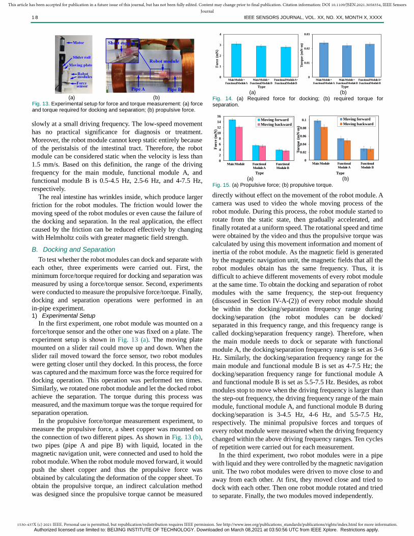
in-pipe experiment. 1) Experimental Setup
In the first experiment, one robot module was mounted on a
force/torque sensor and the other one was fixed on a plate. The
experiment setup is shown in Fig. 13 (a). The moving plate
mounted on a slider rail could move up and down. When the
slider rail moved toward the force sensor, two robot modules
were getting closer until they docked. In this process, the force
was captured and the maximum force was the force required for
docking operation. This operation was performed ten times.
Similarly, we rotated one robot module and let the docked robot
achieve the separation. The torque during this process was
measured, and the maximum torque was the torque required for
separation operation.
In the propulsive force/torque measurement experiment, to
measure the propulsive force, a sheet copper was mounted on
the connection of two different pipes. As shown in Fig. 13 (b),
two pipes (pipe A and pipe B) with liquid, located in the
magnetic navigation unit, were connected and used to hold the
robot module. When the robot module moved forward, it would
push the sheet copper and thus the propulsive force was
obtained by calculating the deformation of the copper sheet. To
obtain the propulsive torque, an indirect calculation method
was designed since the propulsive torque cannot be measured
directly without effect on the movement of the robot module. A
camera was used to video the whole moving process of the
robot module. During this process, the robot module started to
rotate from the static state, then gradually accelerated, and
finally rotated at a uniform speed. The rotational speed and time
were obtained by the video and thus the propulsive torque was
calculated by using this movement information and moment of
inertia of the robot module. As the magnetic field is generated
by the magnetic navigation unit, the magnetic fields that all the
robot modules obtain has the same frequency. Thus, it is
difficult to achieve different movements of every robot module
at the same time. To obtain the docking and separation of robot
modules with the same frequency, the step-out frequency
(discussed in Section IV-A-(2)) of every robot module should
be within the docking/separation frequency range during
docking/separation (the robot modules can be docked/
separated in this frequency range, and this frequency range is
called docking/separation frequency range). Therefore, when
the main module needs to dock or separate with functional
module A, the docking/separation frequency range is set as 3-6
Hz. Similarly, the docking/separation frequency range for the
main module and functional module B is set as 4-7.5 Hz; the
docking/separation frequency range for functional module A
and functional module B is set as 5.5-7.5 Hz. Besides, as robot
modules stop to move when the driving frequency is larger than
the step-out frequency, the driving frequency range of the main
module, functional module A, and functional module B during
docking/separation is 3-4.5 Hz, 4-6 Hz, and 5.5-7.5 Hz,
respectively. The minimal propulsive forces and torques of
every robot module were measured when the driving frequency
changed within the above driving frequency ranges. Ten cycles
of repetition were carried out for each measurement.
In the third experiment, two robot modules were in a pipe
with liquid and they were controlled by the magnetic navigation
unit. The two robot modules were driven to move close to and
away from each other. At first, they moved close and tried to
dock with each other. Then one robot module rotated and tried
to separate. Finally, the two modules moved independently.
0
1
2
3
4
Main Module +
Functional Module A
Main Module +
Functional Module B
Functional Module A+
Functional Module B
Forc
e (m
N)
Type
0
0.01
0.02
0.03
Main Module +
Functional Module A
Main Module +
Functional Module B
Functional Module A+
Functional Module B
Torq
ue
(mN
·m)
Type (a) (b)
Fig. 14. (a) Required force for docking; (b) required torque for separation.
0
2
4
6
8
10
12
14
16
Main Module Functional
Module A
Functional
Module B
Forc
e (
mN
)
Type
Moving forward
Moving backward
0
0.02
0.04
0.06
0.08
0.1
Main Module Functional
Module A
Functional
Module B
Torq
ue (
mN
·m)
Type
Moving forward
Moving backward
(a) (b)
Fig. 15. (a) Propulsive force; (b) propulsive torque.
(a) (b)
Fig. 13. Experimental setup for force and torque measurement: (a) force and torque required for docking and separation; (b) propulsive force.
Authorized licensed use limited to: BEIJING INSTITUTE OF TECHNOLOGY. Downloaded on March 08,2021 at 03:50:56 UTC from IEEE Xplore. Restrictions apply.
1530-437X (c) 2021 IEEE. Personal use is permitted, but republication/redistribution requires IEEE permission. See http://www.ieee.org/publications_standards/publications/rights/index.html for more information.
This article has been accepted for publication in a future issue of this journal, but has not been fully edited. Content may change prior to final publication. Citation information: DOI 10.1109/JSEN.2021.3058354, IEEE SensorsJournal
1·8 IEEE SENSORS JOURNAL, VOL. XX, NO. XX, MONTH X, XXXX
2) Experimental Results and Discussion
The required force and torque for docking and separation are
shown in Fig. 14. The maximal required force for docking
between any two robot modules is 3.1 mN, 2.9 mN, and 2.8 mN,
respectively. The maximal required torque for separation
between any two robot modules is 0.024 mN·m, 0.022 mN·m,
and 0.023 mN·m, respectively. The minimal propulsive force
and torque of every robot module within the driving frequency
range are shown in Fig. 15. The average minimal propulsive
force of the main module, functional module A, and functional
module B is 14.8 mN, 5.5 mN, and 3.9 mN, respectively, when
they move forward. When they move backwards, the average
minimal propulsive forces are 12.1 mN, 5.3 mN, and 3.6 mN,
respectively. The minimal propulsive force of every robot
module is larger than the maximal required force for docking,
and thus any two robot modules can be docked with the
propulsive force. The average minimal propulsive torque of the
main module, functional module A, and functional module B is
0.098 mN·m, 0.054 mN·m, and 0.029 mN·m, respectively,
when they move forward. When they move backwards, the
average minimal propulsive torques of the three robot modules
are 0.082 mN·m, 0.049 mN·m, and 0.028 mN·m. The minimal
propulsive torque of every robot module is larger than the
maximal required torque for separation, and thus any two robot
modules can be separated with the propulsive torque.
Fig. 16 shows the docking and separation procedure of two
robot modules. The main module moved forward and started to
dock with functional module A with the decrease of distance.
Then the two modules completed the docking task with the
propulsive force (position A, Fig. 16 (b)). The docked robot
could move forward and backwards (Fig. 16 (c)-(d)).
Functional module A reversed and completed the separation
task with the propulsive torque (Fig. 16 (e)-(f)). After the
separation, the main module and functional module A could
move independently. Similarly, two functional modules can
also dock and separate from each other. Hence, any two robot
modules can be docked and separated successfully by using the
proposed docking-separation method.
In this experiment, these two robot modules were positioned
in the correct direction, i.e., the thread mechanism of one robot
module facing the claw mechanism of the other one, which
allows two robot modules to dock or separate just by movement
or rotation. In the real environment, the robot modules cannot
turn around if they are in the wrong direction since the external
diameter of the robot modules was designed to be a little
smaller than the internal diameter of the intestine. Therefore, in
the real environment, the camera set in the main module should
be used to observe the pose of the robot modules and allow
robot modules to enter the intestine in correct directions with
this navigation.
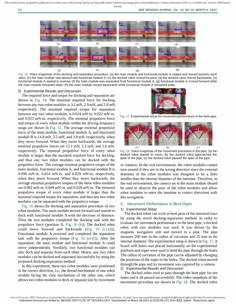
C. Movement Performance in Bent Pipes
1) Experimental Setup
The docked robot can work in bent parts of the intestinal tract
by using the novel docking-separation method. In order to
evaluate the movement performance in the bent pipe, a docked
robot with two modules was used. It was driven by the
magnetic navigation unit and moved in a pipe. The pipe
measure 200 mm in the radius of curvature and 25 mm in the
internal diameter. The experimental setup is shown in Fig. 17. A
board with holes was placed horizontally on the experimental
platform and ropes were used to hold the pipe through the holes.
The radius of curvature of the pipe can be adjusted by changing
the positions of the ropes in the holes. The docked robot moved
through the pipe and its movement was captured by a camera. 2) Experimental Results and Discussion
The docked robot tried to pass through the bent pipe for ten
times and it all passed successfully. The video snapshots of the
movement procedure are shown in Fig. 18. The docked robot
Fig. 16. Video snapshots of the docking and separation procedure: (a) the main module and functional module A rotated and moved towards each other; (b) the main module was docked with functional module A; (c) the docked robot moved forward; (d) the docked robot moved backwards; (e) functional module A started to reverse; (f) the main module was separated from functional module A; (g) functional module A moved forward while
the main module remained static; (h) the main module moved backwards while functional module A remained static.
Fig. 17. Experimental setup for movement performance in the bent pipe.
Fig. 18. Video snapshots of the movement procedure in the pipe: (a) the docked robot started to move; (b) the docked robot approached the apex of the pipe; (c) the docked robot passed the apex of the pipe.
Authorized licensed use limited to: BEIJING INSTITUTE OF TECHNOLOGY. Downloaded on March 08,2021 at 03:50:56 UTC from IEEE Xplore. Restrictions apply.

1530-437X (c) 2021 IEEE. Personal use is permitted, but republication/redistribution requires IEEE permission. See http://www.ieee.org/publications_standards/publications/rights/index.html for more information.
This article has been accepted for publication in a future issue of this journal, but has not been fully edited. Content may change prior to final publication. Citation information: DOI 10.1109/JSEN.2021.3058354, IEEE SensorsJournal
1·8 IEEE SENSORS JOURNAL, VOL. XX, NO. XX, MONTH X, XXXX
started to move and the two robot modules formed an angle
with the movement (position A). The angle reached the
maximal value when it entered the bent parts (position B, Fig.
18 (b)). As Fig. 18 (c) shows, the docked robot finally passed
the bent pipe (position C). The proposed robot could consist of
several modules while the movement performance of the
docked robot with only two modules was tested in this
experiment. This is acceptable as the radius of curvature of the
docked robot will be same when the number of modules
increases. As analyzed in Section III-B, the radius of curvature
depends on the geometric parameters of every two docked
modules and thus the geometric parameters will be the same
when more modules are docked.
D. Accidental Separation Experiment
1) Experimental Setup
When the docked robot moves in the intestinal tract, the force
applied to the docked robot can be divided into axial force and
radial force. The gastric force is the main force during the
operation and it can act as the axial force or radial force for the
docked robot. The docking-separation mechanism is more
susceptible to external forces in its axial direction. Thus, we
tested whether the docked robot can be separated by the gastric
force in the axial direction. The experimental setup is the same
to that in Fig. 13 (a). We pulled one robot module and made it
separate from the other one. The force during this process was
recorded and the maximal force was the force that the docked
robot can provide to resist separation. Ten cycles of repetition
were carried out for each measurement.
In some operational processes, the patient needs to drink
some specific liquid. After the liquid is taken, the liquid starts to
fall down from the pharynx to the stomach due to the gravity.
This type of force mainly affects the docking-separation
mechanism in its radial direction and will result in accidental
separation of the docked robot. So, in the second experiment,
we tested the performance of the docked robot when the water
flow acts on the docking-separation mechanism in the radial
direction. Fig. 19 shows the experimental setup. A vertical pipe
measuring 8 mm in internal diameter, was inserted into a
horizontal pipe (24 mm in internal diameter). The docked robot
was placed at the junction of the two pipes. The vertical pipe
was linked with a pump. The pump can pump water into the
pipe and simulate the impact of water flowing on the docked
robot. Basically, the patient can drink 400 ml of liquid in 60
seconds (6.67 ml/s) and thus the flow of the pump was set as 8
ml/s (larger than 6.67 ml/s). 2) Experimental Results and Discussion
The maximal force that the docked robot can provide to resist
separation was measured. The maximal force is 558±23mN.
[24] declares that the maximal gastric-emptying force is 962.4
dynes/sq cm and thus the maximal force applied to the
proposed robot is 30.23mN. This force is far less than the force
that the docked robot can provide to resist separation. So the
docked robot cannot be separated accidentally with the gastric
forces. Besides, the video snapshots during the water impact
test are shown in Fig. 20. Driven by the magnetic field, the
docked robot shook in situ (stayed at point A) and could not
move forward at first as there is no enough water for the docked
robot to generate propulsive force (Fig. 20 (a)-(c)). Fig. 20 (b)
shows the docked robot suffered from the rush of flowing water
and the docked robot remained the original docking state (Fig.
20 (c)). Finally, the docked robot still remained the docking
state and moved away when it generated a large propulsive
force with the increase of water flow (point B, Fig. 20 (d)).
Therefore, the docked robot cannot be separated accidentally
when the patient drinks liquid during the procedures.
V. CONCLUSION
In this paper, a main-functional module working concept was
introduced and a novel docking-separation method was
proposed. Based on the proposed methods, an MCR with three
modules was fabricated and evaluated through experiments.
The proposed MCR will have the following advantages: (1)
Different functional modules can be selected according to
medical requirements, and it can improve the treatment
efficiency, decrease the manufacturing difficulty, and reduce
the medical costs. (2) The main module can provide assistance
and perform cooperative actions to some complicated surgical
procedures, such as biopsy, drug delivery, or even carry
batteries for further treatments. (3) It can dock reliably and
separate easily without changing existing environmental
constraints or adding any extra types of equipment. (4) The
dock robot can work in some bent parts of the intestinal tract
successfully. However, some limitations still exist inevitably.
The evaluation experiments were conducted in a pipe and the
experimental environment differs from that in the real intestinal
tract, such as the diameter, the velocity and viscosity of the
liquid. More influence factors should be considered in the
evaluation experiments. In further research, these limitations
will be addressed and in-vivo experiments will be carried out.
Fig. 19. Experimental setup for the accidental separation experiment.
Fig. 20. Video snapshots of the accidental separation experiment: (a) the water started to rush the docked robot; (b) the water flow continued
to increase and the docked robot started to rotate; (c) the docked robot remained the docking state; (d) the docked robot moved away in the docking state.
Authorized licensed use limited to: BEIJING INSTITUTE OF TECHNOLOGY. Downloaded on March 08,2021 at 03:50:56 UTC from IEEE Xplore. Restrictions apply.

1530-437X (c) 2021 IEEE. Personal use is permitted, but republication/redistribution requires IEEE permission. See http://www.ieee.org/publications_standards/publications/rights/index.html for more information.
This article has been accepted for publication in a future issue of this journal, but has not been fully edited. Content may change prior to final publication. Citation information: DOI 10.1109/JSEN.2021.3058354, IEEE SensorsJournal
1·8 IEEE SENSORS JOURNAL, VOL. XX, NO. XX, MONTH X, XXXX
REFERENCES
[1] J. Ferlay, I. Soerjomataram, R. Dikshit, S. Eser, C. Mathers, M. Rebelo, D.
Parkin, D. Forman, and F. Bray, “Cancer incidence and mortality
worldwide: Sources, methods and major patterns in GLOBOCAN 2012,”
Int. J. Cancer, vol. 136, no. 5, pp. E359-E386, 2014.
[2] D. Keller, A. Windsor, R. Cohen, and M. Chand, “Colorectal cancer in
inflammatory bowel disease: review of the evidence” Tech. Coloproctol,
vol. 23, pp. 3-13, 2019.
[3] F. Munoz, G. Alici, H. Zhou, W. Li, and M. Sitti, “Analysis of magnetic
interaction in remotely controlled magnetic devices and its application to
a capsule robot for drug delivery,” IEEE/ASME Trans. Mechatronics, vol.
23, no. 1, pp. 298-310, 2018.
[4] S. Yim, and M. Sitti, “Design and rolling locomotion of a magnetically
actuated soft capsule endoscope”, IEEE Trans. Robot., vol. 28, no. 1, pp.
183-194, 2012.
[5] D. Son, X. Dong, and M. Sitti, “A Simultaneous Calibration Method for
Magnetic Robot Localization and Actuation Systems, ” IEEE Trans.
Robot., vol. 35, no. 2, pp. 343-352, Apr. 2019.
[6] M. Gao, C. Hu, Z. Chen, H. Zhang, S. Liu, “Design and fabrication of a
magnetic propulsion system for self-propelled capsule endoscope,” IEEE
Trans. Biomed. Eng., vol. 57, no. 12, pp. 2891-2902, 2010.
[7] Z. Sun, B. Ye, Y. Qiu, X. Cheng, H. Zhang, and S. Liu, “Preliminary
study of a legged capsule robot actuated wirelessly by magnetic torque,”
IEEE Trans. Magn., vol. 50, no. 8, Aug. 2014.
[8] A. Mahoney, and J. Abbott, “Generating rotating magnetic fields with a
single permanent magnet for propulsion of untethered magnetic devices
in a lumen,” IEEE Trans. Robot., vol. 30, no. 2, pp. 411-420, 2014.
[9] N. Nelson, and J. Abbott, “Generating two independent rotating magnetic
fields with a single magnetic dipole for the propulsion of untethered
magnetic devices,” in Proc. IEEE Int. Conf. Robot. Autom., May 2015, pp.
4056-4061.
[10] S. Kim and K. Ishiyama, “Magnetic robot and manipulation for
active-locomotion with targeted drug release,” IEEE/ASME Trans.
Mechatronics, vol. 19, no. 5, pp. 1651-1659, 2014.
[11] D. Ji and S. Kim, “Functional fluid-manipulation using spiral-type
magnetic micromachines as micropumps active valves and channel
selectors,” IEEE Access, vol. 7, pp. 145596-145603, 2019.
[12] J. Gao, and G. Yan, “Design and implementation of a clamper-based and
motor-driven capsule robot powered by wireless power transmission,”
IEEE Access, vol. 7, pp. 138151-138161, 2019.
[13] J. Nam, W. Lee, J. Kim, and G. Jang, “Magnetic helical robot for targeted
drug-delivery in tubular environments,” IEEE/ASME Trans.
Mechatronics, vol. 22, no. 6, pp. 2461-2468, 2017.
[14] G. Jang, S. Jeon, J. Nam, W. Lee, and G. Jang, “A spiral microrobot
performing navigating linear and drilling motions by magnetic gradient
and rotating uniform magnetic field for applications in unclogging
blocked human blood vessels,” IEEE Trans. Magn., vol. 51, no. 11, pp.
1-4, 2015.
[15] B. Jang, J. Nam, W. Lee, and G. Jang “A crawling magnetic robot
actuated and steered via oscillatory rotating external magnetic fields in
tubular environments,” IEEE/ASME Trans. Mechatronics, vol. 22, no. 3,
pp. 1465-1472, 2017.
[16] W. Lee, J. Nam, J. Kim, E. Jung, and G. Jang, “Effective locomotion and
precise unclogging motion of an untethered flexible-legged magnetic
robot for vascular diseases,” IEEE Trans. Ind. Electron., vol. 65, no. 2, pp.
1388-1397, 2018.
[17] Z. Wang, S. Guo, Q. Fu, and J. Guo, “Characteristic evaluation of a
magnetic-actuated microrobot in pipe with screw jet motion,” Microsyst
Technol, vol. 25, no. 2, pp. 719–727, 2019.
[18] Q. Fu, S. Guo, Y. Yamauchi, H. Hirata, and H. Ishihara, “A novel hybrid
microrobot using rotational magnetic field for medical applications,”
Biomed. Microdevices, vol. 17, no. 2, pp. 31-42, 2015.
[19] Q. Fu, S. Zhang, S. Guo, and J. Guo, “Performance evaluation of a
magnetically actuated capsule microrobotic system for medical
applications,” Micromachines, vol. 9, no. 12, pp. 641-656, 2018.
[20] Q. Fu, S. Guo, Q. Huang, H. Hirata, and H. Ishihara, “Development and
evaluation of novel magnetic actuated microrobot with spiral motion
using electromagnetic actuation system,” J. Med. Biol. Eng., vol. 36, no. 4,
pp. 506–514, 2016.
[21] L. Kim, S. Tang, and S. Yoo, “Prototype modular capsule robots for
capsule endoscopies,” in Proc. 13th Int. Conf. Control Autom. Syst.,
Gwangju, Korea, Oct 2013, pp. 350-354.
[22] S. Guo, Q. Yang, L. Bai, and Y. Zhao, “Develop-ment of multiple capsule
robots in pipe,” Micromachines, vol. 9, no. 6, pp. 259-265, 2018.
[23] Z. Nagy, R. Oung, J. J. Abbott and B. J. Nelson, "Experimental
investigation of magnetic self-assembly for swallowable modular robots,"
in Proc. IEEE/RSJ Int. Conf. Intell. Robots Syst., Nice, 2008, pp.
1915-1920.
[24] B. Laulicht, A. Tripathi, V. Schlageter, P. Kucera, and E. Mathiowitz,
“Understanding gastric forces calculated from high-resolution pill
tracking,” in Proc. Natl. Acad. Sci., vol. 107, no.18, pp. 8201-8206, 2010.
Lingling Zheng (S’19) received the M.S.
degrees in Electrical and Information
Engineering from Anhui University of Technology, Anhui, China, in 2018. She is
currently working toward the Ph.D. degree
in Intelligent Mechanical Systems
Engineering, from Kagawa University,
Takamatsu, Japan.
Her current research interests include microrobot and
medical robots, especially capsule robot systems.
Shuxiang Guo (F’21) received the Ph.D.
degree in Mechano-informatics and
Systems from Nagoya University, Japan,
in 1995. He is currently a Full Professor at the Department of Intelligent Mechanical
Systems Engineering, Faculty of
Engineering, Kagawa University, Japan.
He is also a chair professor with the Key
Laboratory of Convergence Medical Engineering System and
Healthcare Technology, The Ministry of Industry and
Information Technology, Beijing Institute of Technology,
China. He has published about 842 refereed journal and
conference papers.
He is the Editor-in-Chief of International Journal of
Mechatronics and Automation. His research interests include medical robot systems, microcatheter systems, and biomimetic
underwater robots.
Zixu Wang (S’19) received the M.S.
degree in Intelligent Mechanical Systems
Engineering from Kagawa University,
Takamatsu, Japan, in 2018. He is working
toward the Ph.D. degree in Intelligent
Mechanical Systems Engineering from
Kagawa University, Japan.
His current research interests include
design, analysis and control of wireless magnetic driven microrobot for biomedical applications.
Takashi Tamiya received the Ph.D.
degree from Medical School, Okayama
University, Okayama, Japan, in 1990. He
had fellowships with Massachusetts
General Hospital, Harvard Medical School
in the USA from 1993 to 1994. He is
currently a Full Professor of Neurological
Surgery with the Faculty of Medicine,
Kagawa University, Japan.
Authorized licensed use limited to: BEIJING INSTITUTE OF TECHNOLOGY. Downloaded on March 08,2021 at 03:50:56 UTC from IEEE Xplore. Restrictions apply.