Embed Size (px)
Citation preview

A Multi-field Bidirectional Fluid Structure Interaction for Human Artery from Clinical Imaging
Rui Wang
Final Report
For the fulfillment of class ASEN5367 Instructor: Dr. Carlos Felippa
May 6, 2006
University of Colorado at Boulder Department of Mechanical Engineering

Abstract: The hemodynamic characteristics of blood flow in the human circulatory
system are significantly changed by the biomechanical properties of the distensible blood
vessel while the fluidic force introduced by the flow could also alter the nature of the
structure. A bio-directional fluid structure interaction model was developed for the
surgical patch after Fontan palliative procedure to accurately simulate the venous return
through vena cava into pulmonary artery under compliant wall boundary based on patient
specific imaging data. The effect of the compliance of the wall will be quantified with
respect to the energy efficiency and hemodynamics of the flow through such connection.
On the other hand, the pressure force and wave form incurred by the flow on the vessel
wall will be investigated, followed by the study how they will change its structure and
induce certain disease such as arterial/venous hypertension.

Introduction: For patients with single ventricle pathology, the Fontan operation by which the
two vena cava are connected directly to the pulmonary arteries excluding the diseased
right ventricle have provided the required palliation to maintain necessary
cardiopulmonary perfusion. Much research has been performed on examining alternative
connection geometries to improve hydrodynamic efficiency through the cavopulmonary
connection, but with a questionable rigid wall assumption. In addition, hypertension
commonly happens in the late stage of those after-Fontan patients which greatly
increased the mortality and morbidity rates and also trigger the development of
atherosclerosis. The difference between the deformation profiles of healthy and stiffer
arteries demonstrates significant and measurable differences particularly in the radial
direction. Furthermore, it has been well documented that there is a relationship between
the genesis and progression of this disease under abnormal flow situations. Fluid
dynamics largely influence the endothelial function of the vessel wall. 1 The most
important effect is the locally distributed mass transfer determined by the oscillating
shear stress, elongated particle resident time and flow recirculation zone, etc. 2 Finally the
pressure wave propagation within the blood vessel can be used as a clinical tool to
diagnose the stiffness of the wall, i.e. atherosclerosis.
Computational method is becoming more popular and powerful in understanding
complicated system involving multifield interaction such as Fluid-Structure, Structure-
Structure, Thermal-Structure, Electromagnetic-Structure etc, and has been used as a
useful tool in supporting the experimental studies. It often enables possible the
acquisition of variable values such as the wall shear loading, pressure wave propagation

etc which are unavailable otherwise. Blood flow through arteries represents a very
complex two way coupling system, the pressure exerted by the blood flow on the vessel
wall can result in large structural deformation which can in turn affect the flow. Fluid
structure interaction stands for a coupling between the 3D Navier-Stokes equations and a
structural field (interior or exterior) which is subjected to linear/large deformation.
Strong coupling between the blood and artery is due to the relatively low stiffness of the
artery compared to that of fluid. Such a highly involved system can raise some numerical
difficulties: (1) because of the nature of the problem – distensible wall and
incompressible flow, the densities of the artery walls and the blood have to be carefully
managed to avoid numerical instabilities; (2) nonlinear displacements are present in the
structure and the fluid problem have to be solved on a moving domain; (3) fake reflection
phenomena from the structural boundary should be taken good care of.
There is much research on how optimize the connection geometry can minimize
the energy loss, but only a few considered the effect of the wall compliance. The present
study will more accurately mimic the biological system from a physiological point of
view. A general idea on how to reconstruct the patient specific geometry, generate the
structural and fluidic mesh, formulate the FSI solution and special concerns will be given
to facilitate such type of study.
Formulation and Implementation: 1) Solid property and modeling:
All arteries and veins consist of three distinct tissue layers, though the latter is
thinner and softer. The innermost layer, the tunica intima, also called tunica interna, is
simple squamous epithelium surrounded by a connective tissue basement membrane with
elastic fibers. It is a single layer of endothelial cells. This part contributes little to the
mechanical properties of the blood vessel. However with age and disease, this is because
the layer the intima becomes thicker and stiffer and provides important mechanical
support. This is known as atherosclerosis. Basically atherosclerosis is the build-up along
the vessel wall of fatty substances, calcium, collagen fibers, cellular waste products and
fibrin, which is referred to as atherosclerotic plaque and make blood vessel have
significantly different mechanical behavior. The middle layer, the tunica media, is
primarily smooth muscle and is usually the thickest layer. It is made up of elastin, smooth
muscle cells, protoglycans, and collagen. Together these form a fibrous helix which is
oriented circumferentially. Such arrangement provides the blood vessel with high
strength, resilience and the ability to resist loads in both the longitudinal and
circumferential directions. To help keep blood flowing, the artery expands with pressure
by activating the smooth muscles in this layer. The outermost layer, which attaches the
vessel to the surrounding tissue, is the tunica externa or tunica adventitia. This part is
mainly consists of connective tissue with some elastic and collagenous fibers.
Mechanically, the adventitia gives structural reinforcement to the vessel and prevent
overstretch and rupture at high levels of mechanical force.

For major blood vessel, the thickness is typically considered to be 5 ~ 10% of its
radius. Therefore, it is appropriate to use thin shell element, defined by two curved
surface coordinates, to model such structure. Since the maximum structural deformation
can approach 15%, a nonlinear displacement needs to be handled in present study. In
shell theories, the bending and membrane strain are merged in the energy expression, and
the coupled deformations including the stretching and change of the middle surface
curvature are required to predict the stress/strain of the shell element.
The governing equation for the structure model is:
ug SBijij &&ρτ =−,
Where τ is the stress, g is the body force, Sρ is the material density, and u&& is the
acceleration.
The governing equation for non-linear dynamic system is:
∑
∑
∑
=
=
=
−∆+=+∆++∆+
iii
TiiV
iii
TiiiV
iii
TiiiV
dVCBBK
dVHHkC
dVHHMtFttRutKuttCuttM
)(
)(
)(
)()()()()(ρ
&
Where M is the mass matrix, C is the damping matrix, K is the master stiffness matrix,
R is the external load, F is the element stress, u is the displacement, iK is the element
damping factor, iH is the element displacement matrix, iC is the elasticity matrix, iB is
the strain displacement matrix and iV is the element volume.
In the present study, we chose low-order general 4-node QUAD shell element
instead of the TRI shell element due to the nature of the problem and some special

numerical concerns. For the geometrically exact TRI element, although it gives excellent
accuracy for some FSI problem and was tested for some structural problems, it is
inappropriate for FSI problem with blood flow because the bending and membrane
phenomena are both present. In contrast, for QUAD shell element, it gives excellent
results for both bending and membrane dominated problem like the coupled structure and
blood flow interaction problem. ANSYS was used in this study to solve the structure part
of the problem.
2) Fluid Property and modeling:
CFX, also from ANSYS Inc, was used to solve the fluid part of the problem.
With the assumption that the blood is homogenous, incompressible and the flow is
laminar, the governing equations are as follows:
)(21
*2
0
T
B
vve
epI
fvvtvv
∇+∇=
+−=
=∇−∇⋅+∂∂=⋅∇
µτ
τρρ
Where v is velocity, Bf is the volume body force, I is the identity matrix and µ is the
dynamic viscosity.
However there is some numerical difficulty regarding the FSI solution with
incompressible fluid. This is caused applying unphysical boundary conditions that lead
to severe convergence problems. Initially the fluid domain is unaware of the constraint
of the structural domain, and vice versa. If the iteration converges this discrepancy will
be settled, but sometimes the initial phase is so ill posed that convergence is practically

impossible to obtain. For example, considering an elastic tube with inlet only, in the start
of the iteration the wall is at rest, if the fluid is incompressible it is impossible to maintain
the continuity since there is no net flux out the domain. Therefore, we applied a small
compressibility to the fluid to deal with this numerical difficulty with the following
formula:
]/1[0 ff kp+= ρρ
Where 0ρ has the value of 1060 kg/m^3 and fk is the bulk modulus of blood.
This bulk modulus parameter is used in the transient algorithm for incompressible
flows, yet it accounts for mild compressibility effects, i.e., non-infinite speeds of sound.
The speed of sound, or the acoustic speed, is the speed at which a sound wave or small
pressure disturbance propagates in a fluid medium. The artificial compressibility has a
natural physical explanation in FSI simulation: the compressibility is defined so that it
makes the fluid follow the elastic response of the structure. Then we have the continuity
as follows:
0)( =⋅∇+∇⋅+∂∂ vpv
tp
k ff
ρρ
Geometry Acquisition:
Two orthonormal images are obtained from bi-plane X-ray angiograms performed
during routine catheterization. A series of points representative of the vessel centerline
for a single branch is identified. A spline is then fit to the initial points and a deformation
model is used to drive the spline to the actual vessel centerline (same procedure is

repeated for each branch). Then bifurcation points, directional vectors and cross
sectional diameters are calculated. Finally a 3D skeleton is created based on those points
and the corresponding vessel diameter. Based on this skeleton, a NURBS based patient
specific geometry is constructed by CAD package Solidworks.
Mesh Generation:
The mesh generator ANSYS ICEMCFD is used to generate both shell and
hexahedron for the structural and fluidic model respectively. Careful attention was given
to the parts of the model whenever there was some sharp geometric change and where
multiple surfaces met. Staggered (non-uniform) mesh algorithm was employed along the
wall boundary of the fluid model to more accurately catch the boundary layer effect in
such regions. In order to maintain a good mesh quality, targeted mesh vortices, edges
and faces were projected particular points, curves and surfaces of the model respectively.
At the end, the mesh quality was checked quantitatively by displaying the value of
determinant, angle and warping ratio etc for each element. In the present study, they had
the minimum values of 0.25, 25○ and 2.06 for the above parameters respectively, which
will pave the way for an accurate, smooth and fast converging FSI solution procedure.
FSI Formulation:
After the numerical models were created for both domains, a FSI simulation was
performed to solve such coupled systems by using staggering partition scheme by using a
tied ANSYS & CFX solver. The fluid solver CFX will start first because it is the driving
force of the whole problem and provides the structure ANSYS solver with pressure load,
then the solid solver starts and feeds the fluid solver with the displacement of the wall
boundary. Since there is a two way feedback between them, a bidirectional FSI should
be performed.
To obtain a solution on the FSI interface, the compatibility condition should be
satisfied all the time which has the following formula:
fS uu =
Form the no slip wall boundary condition, we have:
fS
Sf
nn
uv
ττ =
= &
Then the fluidic force acting on the solid elements on the interface is:
∫= dShF fdτ
where dh represents the virtual displacement of the solid element.
Then the governing equation for the FSI problem can be written as:
=
)](,[
)](,[][
ffSS
SSff
XXF
XdXFXF
τ
where fS XX & are the solution vectors.
A partitioned staggering scheme was used to solve the above problem serially
instead of simultaneously. Convergence was maintained for both fields and the interface
as well.
Boundary conditions and material properties:
The four outer surfaces of the structure were assumed to be stress fee and all
nodes on them were fully constrained, which was due to the reasons of computational
reasons and also is also physiologically reasonable. A single shell layer with a thickness

value of 1 mm was used globally. Elastic modulus of 1E08, Poisson ratio of 0.48 and
material density of 1200 kg/m^3 were assumed for the blood vessel.
The working fluid was assumed to be homogeneous and incompressible with a
dynamic viscosity of 0.003. A normal velocity of 0.25 m/sec was used at both inlet IVC
& SVC while a normal velocity of 0.3 m/sec was used at one outlet RPA and a fixed
pressure value of 0 Pa was used at the other. While these values were in the range of
physiological flow conditions, there were some simplifications used in this study. For
example, the pulsatility of the real blood flow was not considered here, an impedance
outflow boundary condition was more appropriate in a physiological point of view and
only linear wall deformation was used etc. All these will be investigated in the future
study.
Results and Conclusion: The largest displacement of the vessel wall was found to be 7.1E-07 m which was
corresponding to approximately 2% of maximum diameter of the blood vessel diameter.
The areas at the branch junctions have relatively large shear stress values which has a
peak value of 14111 Pa where the IVC, SVC and LPA meets. It was also observed that
the structure has a relatively small rotation in current study. On the other hand, it was
also found larger wall deformation was associated with larger flow rate. The big IVC
branch has a more profound displacement and stress values than the rest three relatively
small model branches. Moreover, the area with significant curvature change also
incurred large wall displacement and stress force like the elbow area of the SVC branch.
Form the results of fluid field solution, a strong wave propagation was seen which is
critical factor influencing the pattern of blood flow and the wall dynamics as well, and it

will be addressed in more details in the future research with more realistic boundary
condition. Strong vortical flow was found at the two outflow boundaries with a maximum
value of 7486 1/s at LPA, which also has a great potential to incur some property changes
on the wall structure such as its stiffness. The shear stress on the wall from the blow was
found to be less than 35 Pa globally with high values happening at the two outflow
boundaries and the regions with big sharp geometry changes, the corresponding shear
strain rate was found to have a peak value of 7126 1/s at the opening of LPA.
In conclusion, by using the advanced bidirectional FSI simulation tool, an
insightful view could be obtained regarding the involved responses of the exterior blood
vessel and the interior blood flow. The problematic regions of the structural wall with
large deformation and stress could be identified, followed by its potential property
changes most importantly the stiffness in present study. In the meanwhile, a detailed
flow pattern characteristics analysis under moving boundary could be performed and
derive the more accurate energy efficiency, the shear force distribution, pressure wave
propagation and finally, the prediction, diagnosis and understanding of the disease
associated with blood vessel.

Legend: Figure1: CAD Model from Solidworks indicating the four branches of the blood
vessel
Figure 2: Structural mesh (Shell) for the vessel wall
Figure 3: Close view of the Shell element at the junction section of the structure
Figure 4: Hexa mesh for the fluid domain (Brick element)
Figure 5: Cross-section view of the Hexa mesh
Figure 6: Deformation of the wall from FEA results
Figure 7: Von Mises stress results from FEA results
Figure 8: Vorticity value from fluid solution
Figure 9: Wall shear stress (WSS) contour from fluid solution

Figure1

Figure 2
Figure 3

Figure 4

Figure 5

Figure 6
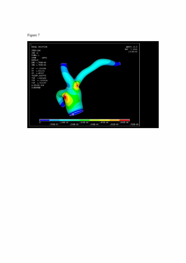
Figure 7

Figure8

Figure 9

References
1. Perktold K, Rappitsch G: Computer-Simulation of Local Blood-Flow and Vessel Mechanics in a Compliant Carotid-Artery Bifurcation Model. Journal of Biomechanics 28:845-856, 1995 2. Caro CG, Fitzgera.Jm, Schroter RC: Proposal of a Shear Dependent Mass Transfer Mechanism for Atherogenesis. Clinical Science 40:P5-&, 1971