Embed Size (px)
Citation preview
IEEE JOURNAL OF EMERGING AND SELECTED TOPICS IN POWER ELECTRONICS
1
Abstract—Brushless doubly-fed induction machines feature
some important advantages, such as high reliability and low
maintenance cost, over alternative solutions for brushless
machine applications. This paper proposes a modulated model
predictive control algorithm for brushless doubly-fed induction
machines, which achieves a fixed switching frequency and
superior system performance. An improvement of power quality
is shown in this paper when compared to the conventional finite
control set-model predictive control. The paper examines the
design and implementation of the modulation technique as well as
presenting simulation and experimental results to verify the
technique’s operation.
Index Terms—Brushless doubly-fed induction machine,
modulated model predictive control.
I. INTRODUCTION
ith the current concern about climate change, the world is
paying more attention to the power sector. To reduce the
emissions of carbon dioxide and minimize reliance on fossil
fuels, wind power has turned into one of the best options for
electrical grid power generation. In the report of ‘the 2016
edition of the Global Wind Energy Outlook,’ it was shown that
wind power could reach 2,110 GW and supply up to 20% of
global electricity by 2030 [1-2]. The generators used in these
wind power applications, therefore, need to supply high-quality
and efficient electrical power to the grid [3-7]. 1 The permanent magnet synchronous machine (PMSM) [3-5]
and the doubly-fed induction machine (DFIM) [6-7] are the
most common machines used in these applications. In a PMSM,
Manuscript received February 1, 2018; revised May 10, 2018 and July 19,
2018; accepted August 11, 2018. This work was supported by National Key R&D Program of China under Grant 2017YFB1200900, the Key Technology
R&D Program of Hunan Province of China under Grant 2018SK2140, the
National Natural Science Foundation of China under Grant No. 61773407, the National Natural Science Foundation of China under Grant No. 61503417 and
FONDECYT Regular 1160690 Project. This paper was recommended for
publication by Editor Joseph Ojo. (Corresponding author: Hanbing Dan.) X. Li, T. Peng, H. Dan, G. Zhang, W. Tang and W. Jin are with the School of
Information Science and Engineering, Central South University, Changsha,
Hunan 410012 China (e-mails: [email protected]; [email protected]; [email protected]; [email protected]; [email protected];
P. Wheeler is with the Department of Electrical and Electronic Engineering, University of Nottingham, Nottingham NG7 2RD, UK.
M. Rivera is with the Faculty of Engineering at Universidad de Talca, Curico, Chile. ([email protected]).
the gearbox is not needed, which leads to high reliability and
longevity, but the price is increased as the power converter
must process all the electrical energy generated. The DFIM
often has a high performance-price ratio when adopted in wind
generation applications, partly due to the fact that the power
converter only processes a fraction of the electrical energy
generated. Other advantages of the DFIM include wide
operational speed range, variable speed operation, and full
power control capability. However, the gearbox and brushes of
DFIM can lead to low reliability and higher maintenance costs
[6].
To obtain improved performance, the dual stator winding
induction machine (DSWIM) and brushless doubly-fed
induction machine (BDFIM) have been used as alternatives to
the DFIM. The DSWIM is suitable for electric aircraft
applications [8-11]. In this paper, due to the absence of brushes,
the maintenance costs of a BDFIM are lower than a traditional
doubly-fed machine. The BDFIM is, therefore, suitable for
drive systems in applications requiring minimal maintenance,
such as Wind Energy Conversion Systems (WECS) [12-13].
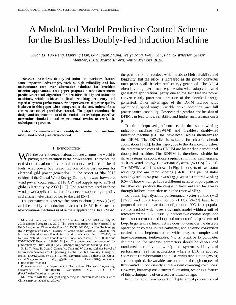
The BDFIM, which is shown in Fig. 1, consists of two stator
windings and one rotor winding [14-16]. The pair of stator
windings includes a power winding (PW) and a control winding
(CW). These windings have a different number of pole pairs so
that they can produce the magnetic field and transfer energy
through indirect interaction using the rotor winding.
To obtain high dynamic performance, vector control (VC)
[17-23] and direct torque control (DTC) [24-27] have been
proposed for this machine configuration. VC is a popular
control method which uses a dynamic model within a unified
reference frame. A VC usually includes two control loops, one
fast inner current control loop, and one outer flux/speed control
loop. In general, its linear nature does not consider the discrete
operation of voltage source converter, and a vector conversion
needed in the implementation, which may be complex and
time-consuming. Furthermore, VC is sensitive to parameter
detuning, so the machine parameters should be chosen and
monitored carefully to satisfy the system stability and
performance [22]. In applications where a DTC is applied,
coordinate transformation and pulse-width modulation (PWM)
are not required, the variables are controlled through torque and
flux control in both steady and transient operating conditions.
However, low-frequency current fluctuation, which is a feature
of this technique, is often a serious disadvantage.
With the rapid development of digital signal processors and
A Modulated Model Predictive Control Scheme
for the Brushless Doubly-Fed Induction Machine
Xuan Li, Tao Peng, Hanbing Dan, Guanguan Zhang, Weiyi Tang, Weiyu Jin, Patrick Wheeler, Senior
Member, IEEE, Marco Rivera, Senior Member, IEEE
W
IEEE JOURNAL OF EMERGING AND SELECTED TOPICS IN POWER ELECTRONICS
2
power devices, the finite control set-model predictive control
(FCS-MPC) is now being considered as an alternative control
method of power converters due to its advantages such as fast
dynamic response, easy inclusion of nonlinearities and
constraints of the system, and the flexibility to include other
system requirements in the controller [28-30]. However, the
switching frequency is variable, which decreases the system
performance. To achieve a fixed switching frequency,
modulated model predictive control (MMPC) has been
proposed [31-35].
This paper presents the application of an MMPC strategy for
the BDFIM. MMPC incorporates a modulation technique
inside the FCS-MPC algorithm. The modulation uses a cost
function to minimize the predictive algorithm by choosing two
active vectors and one zero vector. Compared with FCS-MPC,
MMPC achieves a fixed switching frequency, higher reactive
power control accuracy, and lower torque ripple. Simulation
and experimental results are presented to show the feasibility
and effectiveness of the proposed approach as well as to allow
an analysis of the performance. The presented MMPC strategy
in this paper has been described in [36], more principle details,
simulation and experimental results are added in this paper.
This paper is organized as follows. In Section II, the MMPC
scheme for BDFIM is described, which includes the model of
BDFIM and the theoretical comparison of MMPC and
FCS-MPC. Then in section III and IV, simulation results of
FCS-MPC and MMPC are presented to demonstrate the
feasibility of the proposed methods, and experimental results
verify the correctness of the simulation.
Fig. 1. The basic structure of a BDFIM.
II. MMPC SCHEME FOR THE BDFIM
A. Model of the BDFIM
The BDFIM is composed of two three-phase stator windings
and a special three-phase rotor winding. One of the stator
winding is denoted as power winding (PW) and the other one is
called control winding (CW).
Assume that the PW is directly connected to the grid in
positive phase sequence, and the CW is connected to the grid
via a voltage source inverter in reverse phase sequence
connection. To simplify the model of BDFIM, the harmonic
magnetic fields and their coupling effects are ignored. PW, CW,
and rotor are described in dq reference frames which based on
PW flux orientation with p1-type pole-pair. The voltages and
currents vectors of PW, CW, and rotor, which are represented
as , , and , should be transformed from their reference
frames to the dq reference frame.
1 1
1 1
j te
−=dq αβ
x x (1)
( )1 1 2*
( -( ) )-dq αβ2
2 2x x − +
= rj p p te (2)
1 1( - )rj p te
−=dq αβr
r rx x (3)
where , are the angular frequencies of PW and CW;
and are pole pairs of PW and CW; is the angular speed of
the rotor. To simplify the expressions, the vector superscripts
dq are removed.
The model of the BDFIM with the voltage and flux equations
in dq reference frame can be shown as follows.
1 1
dR j
dt1
1 1 1
φu = i + + φ (4)
( )2 1 1 2( )r
dR j p p
dt = + + − +2
2 2 2
φu i φ (5)
( )1 10 r r
dR j p
dt = + + −r
r r
φi φ (6)
1 1 rrL M= +1 1φ i i (7)
2 2r rL M= +2 2φ i i (8)
1 2rr rL M M= + +r r 1 2φ i i i (9)
( ) ( )1
*
1 2 2
*3 3Im[ ] Im[ ]
2 21 2φ i φ i= +eT p p (10)
*
1
3Im ([ ) ]
21v i=Q (11)
( )1 2 1 2 rp p = +− (12)
re r L
dJ T T
dt
= − − (13)
where , , , , , , and are the PW stator
voltage vector, CW stator voltage vector, PW stator current
vector, CW stator current vector, rotor current vector, PW
stator flux vector, CW stator flux vector and rotor flux vector;
, , , , and are the PW stator resistance, CW
stator resistance, rotor resistance, PW stator inductance, CW
stator inductance and rotor inductance; is the coupling
inductance between the PW stator and rotor winding; is the
coupling inductance between the CW stator and rotor winding;
, and Q are the electromagnetic torque, load torque and
reactive power; J and μ are the moments of inertia and friction
coefficient; * is the conjugate symbol; Im is a symbol to obtain
the imaginary part of vector.
Since the rotor resistance is much lower than its reactance,
reference [37] ignores the rotor resistance and verifies the
feasibility of the simplified model. When the BDFIM is
running at steady state, , equation (6) can be simplified
as:
( )1 10 r rR j p = + −r ri φ (14)
Since the rotor resistance has been ignored in this simplified
model, the rotor flux The simplified model is derived
as follows:
IEEE JOURNAL OF EMERGING AND SELECTED TOPICS IN POWER ELECTRONICS
3
d
dtA B
d
dt
= +
1
1
2
1
2 2
i
i
i
u
ui (15)
( )1 1 12
1
2
1
q d dv M iQ
L
−= (16)
( )2
12 12 2 2 1 1
1 22
1 1 2
3
2
r
e d q
M N M L LT i
L L
−= (17)
where 1
1 1 12
12 2 2
1 1 1 1 1 12
1 1 2 12 2 1 1 2 2 2
*
[ ( ) ] [ ( ) ]r r
L MA
M L
R j L j M
j p p M R j p p L
−
=
− − − − − + − − − +
1
1 1 12
12 2 2
L MB
M L
−
=
,
2
11
1
1 r
r
M
L L = − ,
2
22
2
1 r
r
M
L L = − ,
2 2
1 2
1 2 1 2
1 r rM M
L L L L = − − ,
1 212
r r
r
M MM
L= − , 1 2rN p p= +
A discrete BDFIM model can be derived from (15) by using
a forward Euler approximation and the relation between the
discrete-time variables can be described as:
G H
= +
k+1 k k
1 1 1
k+1 k k
2 2 2
i i u
i i u (18)
where , , I is a 2*2 unit matrix,
is the sample period.
B. Current control of the BDFIM
a) Model of the converter
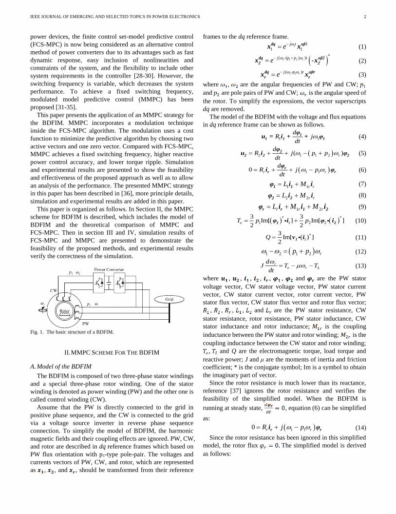
Fig. 2 shows the topology of a back-to-back bidirectional
power converter and its valid switching states. This converter
prohibits the state that two switches in each leg are turned on at
the same time, therefore the short-circuit switch states should
be precluded. Six active vectors are represented by switching
states 1-6 and the zero vectors are represented by switching
states 7-8. Sj (j {1, 2, 3, 4, 5, 6}) equals to ‘1’ when switch Sj is
turned on and equals to ‘0’ when switch Sj is turned off,
respectively. Assume the value of dc-link voltage is . A
constant dc-link voltage is achieved from the three-phase
voltage source rectifier which adopts a Space Vector Pulse
Width Modulation (SVPWM) strategy [38]. The output voltage
in dq reference frame is expressed as:
( ) ( )1 3 322 4
1-(*
)
1 3 5
2
32u
+−− −= −rp p j jj t
dce S S e S e u (19)
(a)
(b)
Fig. 2. The topology of a bidirectional power converter (a) and its valid
switching states (b).
b) Control strategies of FCS-MPC and MMPC
A superior control strategy could make the controlled
variables catch up with the corresponding reference value
respectively at the end of the sampling period. The operation of
the BDFIM is required to satisfy two targets: (i), the desired
reactive power *Q in PW should be obtained; (ii), the speed of
the BDFIM should track the reference speed. According to
equation (16), the target (i) can be obtained by setting:
1 1 1
12 12 1
**
2dd
q
L Qi
M M v
= − (20)
To achieve the target (ii), a proportional-integral (PI)
regulator shown in Fig. 3 is adopted. The output of this PI
regulator is a reference electromagnetic torque, which can be
satisfied with an appropriate according to equation (17).
The reference value is:
( )
2 ** 1 1 22 2
12 1 12 2 2 1 1
2
3
eq
r d
L L Ti
M N M L L
=
− (21)
The predictive CW current in the next sampling period can
be derived from the discrete BDFIM model. To obtain these
two targets, the cost function g is defined as the deviation
between the reference CW current and the predictive CW
current. And it is expressed as:
( ) ( )2 2
* *
2 2 2 2d d q qg i i i i= − + − (22)
IEEE JOURNAL OF EMERGING AND SELECTED TOPICS IN POWER ELECTRONICS
4
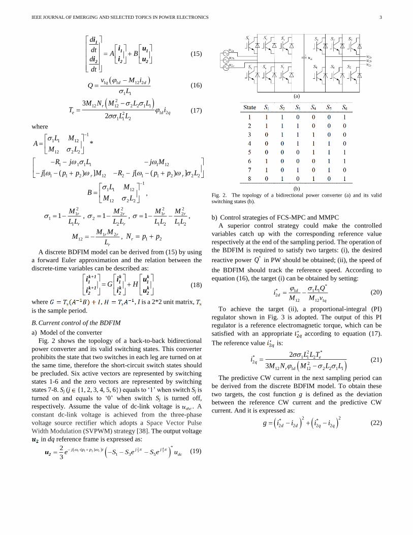
Fig. 3. PI-MMPC control scheme of a MMPC strategy for the BDFIM.
1) FCS-MPC
The FCS-MPC is a well-known technique which uses the
finite number of all possible switching states generated by the
power converter to realize the optimal control. In this paper, the
possible switching states are generated by the bidirectional
power converter shown in Fig. 2. Eight predictive values are
evaluated with the reference in the cost function g. Then, the
first optimum vector switching state with the least value of the
evaluation is chosen in the next sampling time. Fig. 4 shows the
diagram of an FCS-MPC for the BDFIM.
Fig. 4. Diagram of an FCS-MPC for the BDFIM.
2) MMPC
The proposed MMPC strategy shown in Fig. 3 evaluates an
extra cost function based on the FCS-MPC. To obtain a fixed
switching frequency, two adjacent active vectors and , and
a zero vector will be chosen in each sampling period. It is
assumed that the cost functions g of these vectors are gj, gk and
g0 respectively. , and are the duty cycles of these
vectors. is the sampling period. K is a positive constant. The
duty cycles for the two active vectors are calculated by solving:
0 0
0
/
/
/
1
j j
k k
j k
d K g
d K g
d K g
d d d
=
=
= + + =
(23)
Thus, the duty cycles for each vector are given as:
0
0 0
0
0 0
0
0 0
=
+ +
=+ +
= + +
kj
j j k k
j
k
j j k k
j k
j j k k
g gd
g g g g g g
g gd
g g g g g g
g gd
g g g g g g
(24)
Then the new cost function Cost can be defined as:
0 0j j k kCost d g d g d g= + + (25)
At last, the two active vectors of the minimum cost function
value are the optimal solutions and are used to the bidirectional
power converter at the next sampling time. Thereafter, the
appropriate ratio which is determined by the duty cycles ( ,
, ) is shown in Fig. 5 within each sampling period.
Fig. 5. Switching pattern.
C. Proposed PI-MMPC control scheme
Fig. 3 shows the diagram of the proposed hybrid PI-MMPC
scheme, which can be divided into two parts: outer speed loop
and inner current loop.
The outer speed loop consists of a rotor speed regulator and a
torque transfer function. The rotor speed regulator is used to
adjust the rotor speed to the set value. PI-based controllers will
be used for the outer loop. The inner current loop consists of a
reactive power transfer function, an MMPC controller of CW
current and a phase-locked loop (PLL). The reference current
value is obtained according to the torque transfer function.
The reference current value is obtained according to the
IEEE JOURNAL OF EMERGING AND SELECTED TOPICS IN POWER ELECTRONICS
5
reactive power transfer function. The MMPC controller
generates two active vectors and a zero vector according to the
cost function, which are used to the converter at the next
sampling time. Fig. 6 shows the calculation of and the PLL
is used to track the phase angle of the three-phase grid voltage
accurately.
Fig. 6. Calculation of .
III. SIMULATION RESULTS
The operation and implementation of an MMPC for the
BDFIM are verified using a simulation in MATLAB/Simulink.
Table I shows simulation parameters of the system. According
to equation (12), when PW and CW rated frequency are
respectively 50 Hz and 0 Hz, the natural rotor speed is 750
r/min. The PW stator is directly connected to the grid. And the
CW stator is fed by the back-to-back bidirectional power
converter.
TABLE I PARAMETERS OF BDFIM
To confirm the effectiveness and superiority of the MMPC,
the results of the MMPC are compared with the results obtained
by the conventional FCS-MPC at sub-synchronous and
super-synchronous speeds. Two tests have been carried out to
verify the responses both in FCS-MPC and MMPC.
Test 1: the expected reactive power is 0 Var, the reference
rotor speed increases from 600 r/min to 800 r/min during the
period 3-5 seconds when the load torque is 50 N·m.
Test 2: at t = 3 s, the load torque changes from 50 N·m to 25
N·m, and the reference of rotor speed is 600 r/min.
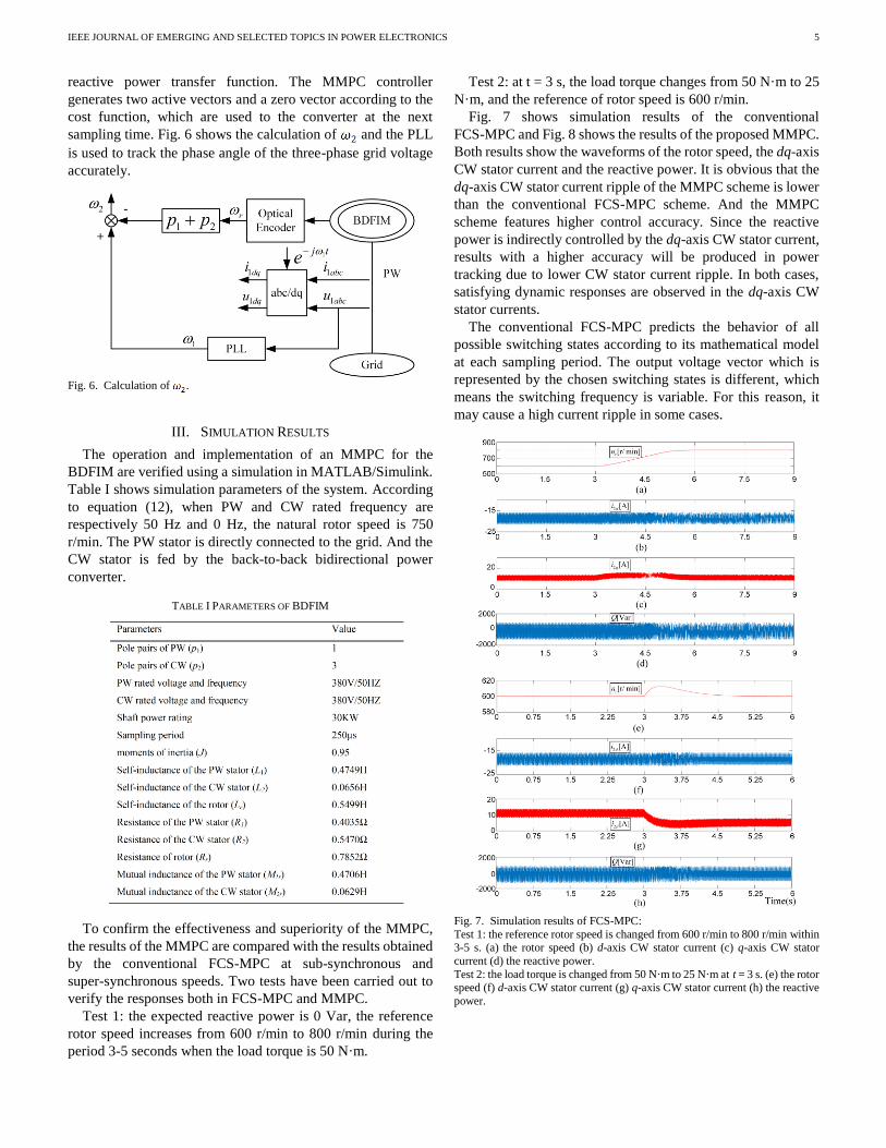
Fig. 7 shows simulation results of the conventional
FCS-MPC and Fig. 8 shows the results of the proposed MMPC.
Both results show the waveforms of the rotor speed, the dq-axis
CW stator current and the reactive power. It is obvious that the
dq-axis CW stator current ripple of the MMPC scheme is lower
than the conventional FCS-MPC scheme. And the MMPC
scheme features higher control accuracy. Since the reactive
power is indirectly controlled by the dq-axis CW stator current,
results with a higher accuracy will be produced in power
tracking due to lower CW stator current ripple. In both cases,
satisfying dynamic responses are observed in the dq-axis CW
stator currents.
The conventional FCS-MPC predicts the behavior of all
possible switching states according to its mathematical model
at each sampling period. The output voltage vector which is
represented by the chosen switching states is different, which
means the switching frequency is variable. For this reason, it
may cause a high current ripple in some cases.
Fig. 7. Simulation results of FCS-MPC:
Test 1: the reference rotor speed is changed from 600 r/min to 800 r/min within 3-5 s. (a) the rotor speed (b) d-axis CW stator current (c) q-axis CW stator
current (d) the reactive power.
Test 2: the load torque is changed from 50 N·m to 25 N·m at t = 3 s. (e) the rotor speed (f) d-axis CW stator current (g) q-axis CW stator current (h) the reactive
power.
IEEE JOURNAL OF EMERGING AND SELECTED TOPICS IN POWER ELECTRONICS
6
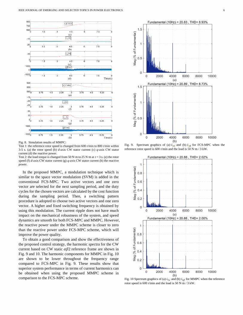
Fig. 8. Simulation results of MMPC: Test 1: the reference rotor speed is changed from 600 r/min to 800 r/min within
3-5 s. (a) the rotor speed (b) d-axis CW stator current (c) q-axis CW stator
current (d) the reactive power. Test 2: the load torque is changed from 50 N·m to 25 N·m at t = 3 s. (e) the rotor
speed (f) d-axis CW stator current (g) q-axis CW stator current (h) the reactive
power.
In the proposed MMPC, a modulation technique which is
similar to the space vector modulation (SVM) is added in the
conventional FCS-MPC. Two active vectors and one zero
vector are selected for the next sampling period, and the duty
cycles for the chosen vectors are calculated by the cost function
during the sampling period. Then, a switching pattern
procedure is adopted to choose two active vectors and one zero
vector. A higher and fixed switching frequency is obtained by
using this modulation. The current ripple does not have much
impact on the mechanical robustness of the system, and speed
dynamics are smooth for both FCS-MPC and MMPC. However,
the reactive power under the MMPC scheme is closer to zero
than the reactive power under FCS-MPC scheme, which will
improve the power quality.
To obtain a good comparison and show the effectiveness of
the proposed control strategy, the harmonic spectra for the CW
current based on CW static 𝛼𝛽2 reference frame are shown in
Fig. 9 and 10. The harmonic components for MMPC in Fig. 10
are shown to be lower throughout the frequency range
compared to FCS-MPC in Fig. 9. These results show that
superior system performance in terms of current harmonics can
be obtained when using the proposed MMPC scheme in
comparison to the FCS-MPC scheme.
(a)
(b)
Fig. 9. Spectrum graphics of (a) and (b) for FCS-MPC when the
reference rotor speed is 600 r/min and the load is 50 N·m / 3 kW.
(a)
(b)
Fig. 10 Spectrum graphics of (a) and (b) for MMPC when the reference
rotor speed is 600 r/min and the load is 50 N·m / 3 kW.
IEEE JOURNAL OF EMERGING AND SELECTED TOPICS IN POWER ELECTRONICS
7
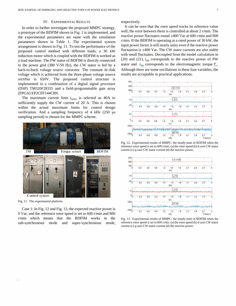
IV. EXPERIMENTAL RESULTS
In order to further investigate the proposed MMPC strategy,
a prototype of the BDFIM shown in Fig. 1 is implemented, and
the experimental parameters are same with the simulation
parameters shown in Table 1. The experimental system
arrangement is shown in Fig. 11. To test the performance of the
proposed control method with different loads, a 30 kW
induction motor which is coupled with the BDFIM is worked as
a load machine. The PW stator of BDFIM is directly connected
to the power grid (380 V/50 Hz), the CW stator is fed by a
back-to-back voltage source converter. The constant dc-link
voltage which is achieved from the three-phase voltage source
rectifier is 650V. The proposed control structure is
implemented in a combination of a digital signal processor
(DSP) TM320F28335 and a field-programmable gate array
(FPGA) EP2C8T144C8N.
The maximum current limit is selected as 40A to
sufficiently supply the CW current of 20 A. This is chosen
within the actual maximum limits for control design
verification. And a sampling frequency of 4 kHz (250 μs
sampling period) is chosen for the MMPC scheme.
Fig. 11. The experimental platform.
Case 1: In Fig. 12 and Fig. 13, the expected reactive power is
0 Var, and the reference rotor speed is set to 600 r/min and 800
r/min which means that the BDFIM works in the
sub-synchronous mode and super-synchronous mode,
respectively.
It can be seen that the rotor speed tracks its reference value
well, the error between them is controlled at about 2 r/min. The
reactive power fluctuates round ±400 Var at 600 r/min and 800
r/min. If the BDFIM is operating at a rated power of 30 kW, the
input power factor is still nearly unity even if the reactive power
fluctuation is ±400 Var. The CW stator currents are also stable
with small fluctuates. Decoupled from the model calculation in
(20) and (21), corresponds to the reactive power of PW
stator and corresponds to the electromagnetic torque .
Although there are some oscillations in these four variables, the
results are acceptable in practical applications.
Fig. 12. Experimental results of MMPC: the steady-state of BDFIM when the
reference rotor speed is set to 600 r/min. (a) the rotor speed (b) d-axis CW stator current (c) q-axis CW stator current (d) the reactive power.
Fig. 13. Experimental results of MMPC: the steady-state of BDFIM when the
reference rotor speed is set to 800 r/min. (a) the rotor speed (b) d-axis CW stator
current (c) q-axis CW stator current (d) the reactive power.
.
IEEE JOURNAL OF EMERGING AND SELECTED TOPICS IN POWER ELECTRONICS
8
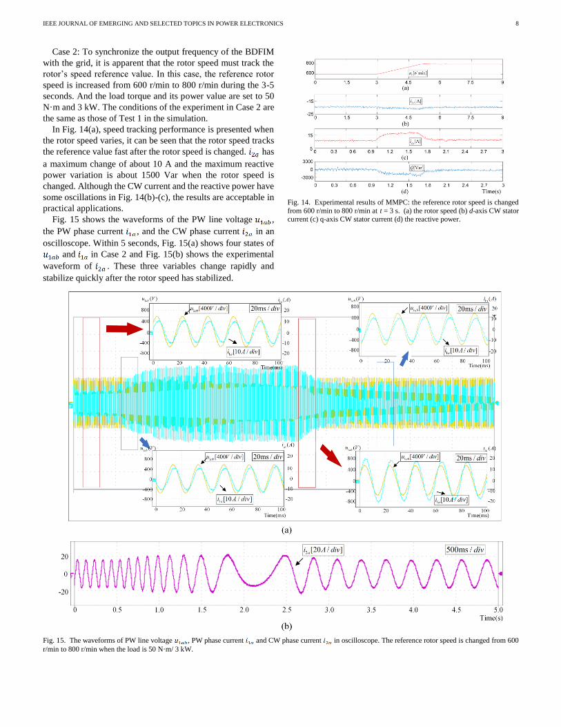
Case 2: To synchronize the output frequency of the BDFIM
with the grid, it is apparent that the rotor speed must track the
rotor’s speed reference value. In this case, the reference rotor
speed is increased from 600 r/min to 800 r/min during the 3-5
seconds. And the load torque and its power value are set to 50
N·m and 3 kW. The conditions of the experiment in Case 2 are
the same as those of Test 1 in the simulation.
In Fig. 14(a), speed tracking performance is presented when
the rotor speed varies, it can be seen that the rotor speed tracks
the reference value fast after the rotor speed is changed. has
a maximum change of about 10 A and the maximum reactive
power variation is about 1500 Var when the rotor speed is
changed. Although the CW current and the reactive power have
some oscillations in Fig. 14(b)-(c), the results are acceptable in
practical applications.
Fig. 15 shows the waveforms of the PW line voltage ,
the PW phase current , and the CW phase current in an
oscilloscope. Within 5 seconds, Fig. 15(a) shows four states of
and in Case 2 and Fig. 15(b) shows the experimental
waveform of . These three variables change rapidly and
stabilize quickly after the rotor speed has stabilized.
Fig. 14. Experimental results of MMPC: the reference rotor speed is changed
from 600 r/min to 800 r/min at t = 3 s. (a) the rotor speed (b) d-axis CW stator current (c) q-axis CW stator current (d) the reactive power.
Fig. 15. The waveforms of PW line voltage , PW phase current and CW phase current in oscilloscope. The reference rotor speed is changed from 600
r/min to 800 r/min when the load is 50 N·m/ 3 kW.
IEEE JOURNAL OF EMERGING AND SELECTED TOPICS IN POWER ELECTRONICS
9
Case 3: Load change may be required during the operation of
the BDFIM. To evaluate the load impact on the proposed
control method, in this case, the load is reduced from 50 N·m/ 3
kW to 25 N·m/ 1.5kW. The rotor speed is set at 600 r/min and
remains constant. The conditions of the experiment in Case 3
are the same as those of Test 2 in the simulation.
In Fig. 16, as the load changes, a few adjustments take place
in the rotor speed, CW current, and the reactive power.
Moreover, the rotor speed increases because the
electromagnetic torque is larger than the load torque at the
change moment, then the rotor speed recovers to its original
state when the electromagnetic torque decreases due to the
decrease of . After about 0.2 seconds, these four variables
tend to reach a steady state and decreases to a lower value in
the steady state.
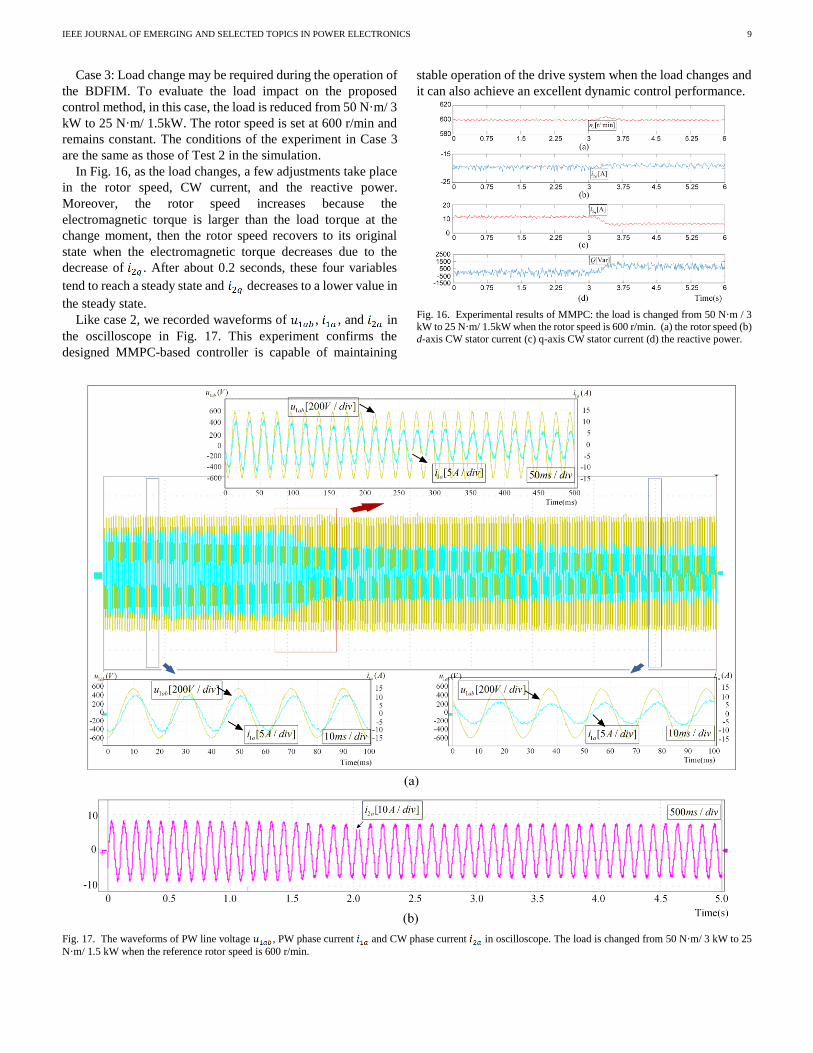
Like case 2, we recorded waveforms of , , and in
the oscilloscope in Fig. 17. This experiment confirms the
designed MMPC-based controller is capable of maintaining
stable operation of the drive system when the load changes and
it can also achieve an excellent dynamic control performance.
Fig. 16. Experimental results of MMPC: the load is changed from 50 N·m / 3
kW to 25 N·m/ 1.5kW when the rotor speed is 600 r/min. (a) the rotor speed (b)
d-axis CW stator current (c) q-axis CW stator current (d) the reactive power.
Fig. 17. The waveforms of PW line voltage , PW phase current and CW phase current in oscilloscope. The load is changed from 50 N·m/ 3 kW to 25
N·m/ 1.5 kW when the reference rotor speed is 600 r/min.
IEEE JOURNAL OF EMERGING AND SELECTED TOPICS IN POWER ELECTRONICS
10
Compared with the simulation results, the tracking error of
the CW current and the reactive power are larger in
experiments, which are mainly caused by the non-ideal power
sources, inaccurate motor parameters, and the converter losses.
However, the results are acceptable in practical applications. In
sum, the correctness and merits of the MMPC used in a BDFIM
are verified. Through the proposed method, excellent dynamic
response and low ripple current are obtained.
V. CONCLUSION
An MMPC scheme with a fixed switching frequency for the
BDFIM has been proposed in this paper. The modulation
technique incorporates the SVM to the FCS-MPC. With a
simple implementation structure, a satisfying tracking
performance of the reactive power and rotor speed are achieved
by a cost function. Compared with the results of the FCS-MPC,
low current ripple and higher control accuracy are obtained. An
outstanding system performance has been achieved and
simulation results show the feasibility and effectiveness of the
proposed method. The steady-state performance and fast
dynamic performance of MMPC are verified by experimental
results.
The MMPC retains the desirable advantage over the
FCS-MPC, such as fast dynamic performance. Moreover, a
fixed switching frequency is obtained by using a PWM scheme
in this technique. The MMPC strategy is also dependent on the
machine parameters, the evaluation on parameter sensitivity of
the MMPC strategy is worthy of study in the future work.
REFERENCES
[1] F. Blaabjerg and K. Ma, "Wind Energy Systems," in Proceedings of the
IEEE, vol. 105, no. 11, pp. 2116-2131, Nov. 2017.
[2] Global wind energy council. (Oct. 2016). Global wind energy outlook | 2016. [Online]. Available:
http://www.gwec.net/publications/global-wind-energy-outlook/
global-wind-energy-outlook-2016/ [3] S. Ekanayake, R. Dutta, M. F. Rahman and D. Xiao, "Direct torque and
flux control of interior permanent magnet synchronous machine in deep
flux-weakening region," IET Electric Power Applications, vol. 12, no. 1, pp. 98-105, 1 2018.
[4] Y. Miao, H. Ge, M. Preindl, J. Ye, B. Cheng and A. Emadi, "MTPA fitting and torque estimation technique based on a new flux-linkage
model for interior-permanent-magnet synchronous machines," IEEE
Transactions on Industry Applications, vol. 53, no. 6, pp. 5451-5460, Nov.-Dec. 2017.
[5] A. H. Abosh, Z. Q. Zhu and Y. Ren, "Reduction of torque and flux ripples
in space vector modulation-based direct torque control of asymmetric permanent magnet synchronous machine," IEEE Transactions on Power
Electronics, vol. 32, no. 4, pp. 2976-2986, April 2017.
[6] L. J. Cai and I. Erlich, "Doubly fed induction generator controller design for the stable operation in weak grids," IEEE Transactions on Sustainable
Energy, vol. 6, no. 3, pp. 1078-1084, July 2015.
[7] R. Cardenas, R. Pena, S. Alepuz and G. Asher, "Overview of control systems for the operation of DFIGs in wind energy applications," IEEE
Transactions on Industrial Electronics, vol. 60, no. 7, pp. 2776-2798,
July 2013. [8] H. Xu, F. Bu, W. Huang, Y. Hu, H. Liu and Y. Zhao, "Analysis,
comparison, and discussion of control strategies for dual stator-winding
induction generator DC generating system," IEEE Journal of Emerging and Selected Topics in Power Electronics, vol. 4, no. 3, pp. 1007-1014,
Sept. 2016.
[9] F. Bu, S. Zhuang, W. Huang, N. Su and Y. Hu, "Asymmetrical operation analysis for dual stator-winding induction generator variable frequency
AC generating system with unbalanced loads," IEEE Transactions on
Industrial Electronics, vol. 64, no. 1, pp. 52-59, Jan. 2017. [10] H. Xu, F. Bu, W. Huang, Y. Hu and H. Liu, "Control and performance of
five-phase dual stator-winding induction generator DC generating
system," IEEE Transactions on Industrial Electronics, vol. 64, no. 7, pp. 5276-5285, July 2017.
[11] S. Basak and C. Chakraborty, "A new optimal current control technique
for dual stator winding induction generator," IEEE Journal of Emerging and Selected Topics in Power Electronics, vol. 5, no. 2, pp. 820-832, June
2017.
[12] V. Yaramasu, A. Dekka, M. J. Durán, S. Kouro and B. Wu, "PMSG-based wind energy conversion systems: survey on power converters and
controls," IET Electric Power Applications, vol. 11, no. 6, pp. 956-968, 7
2017. [13] N. K. Swami Naidu and B. Singh, "Doubly fed induction generator for
wind energy conversion systems with integrated active filter capabilities,"
IEEE Transactions on Industrial Informatics, vol. 11, no. 4, pp. 923-933, Aug. 2015.
[14] L. J. Hunt, "A new type of induction motor," Electrical Engineers,
Journal of the Institution of, vol. 39, no. 186, pp. 648-667, September 1907.
[15] R. Li, A. Wallace, R. Spee and Y. Wang, "Two-axis model development
of cage-rotor brushless doubly-fed machines," IEEE Transactions on Energy Conversion, vol. 6, no. 3, pp. 453-460, Sept. 1991.
[16] S. Williamson, A. C. Ferreira and A. K. Wallace, "Generalised theory of the brushless doubly-fed machine. I. Analysis," IEE Proceedings -
Electric Power Applications, vol. 144, no. 2, pp. 111-122, Mar 1997.
[17] L. Sun, Y. Chen, J. Su, D. Zhang, L. Peng and Y. Kang, "Decoupling network design for inner current loops of stand-alone brushless doubly
fed induction generation power system," IEEE Transactions on Power
Electronics, vol. 33, no. 2, pp. 957-963, Feb. 2018. [18] F. Barati, R. McMahon, S. Shao, E. Abdi and H. Oraee, "Generalized
vector control for brushless doubly fed machines with nested-loop rotor,"
IEEE Transactions on Industrial Electronics, vol. 60, no. 6, pp. 2477-2485, June 2013.
[19] A. Zhang, X. Wang, W. Jia and Y. Ma, "Indirect stator-quantities control
for the brushless doubly fed induction machine," IEEE Transactions on Power Electronics, vol. 29, no. 3, pp. 1392-1401, March 2014.
[20] R. Zhao, A. Zhang, Y. Ma, X. Wang, J. Yan and Z. Ma, "The dynamic
control of reactive power for the brushless doubly fed induction machine with indirect stator-quantities control scheme," IEEE Transactions on
Power Electronics, vol. 30, no. 9, pp. 5046-5057, Sept. 2015.
[21] J. Chen, W. Zhang, B. Chen and Y. Ma, "Improved vector control of brushless doubly fed induction generator under unbalanced grid
conditions for offshore wind power generation,"IEEE Transactions on
Energy Conversion, vol. 31, no. 1, pp. 293-302, March 2016. [22] P. Han, M. Cheng, X. Wei and N. Li, "Modeling and performance
analysis of a dual-stator brushless doubly fed induction machine based on
spiral vector theory," IEEE Transactions on Industry Applications, vol. 52, no. 2, pp. 1380-1389, March-April 2016.
[23] G. Zhang, J. Yang, Y. Sun, M. Su, W. Tang, Q. Zhu and H. Wang,, "A
robust control scheme based on ISMC for the brushless doubly fed induction machine," IEEE Transactions on Power Electronics, vol. 33, no.
4, pp. 3129-3140, April 2018.
[24] S. J. Fattahi and A. A. Khayyat, "Direct torque control of brushless
doubly-fed induction machines using fuzzy logic," 2011 IEEE Ninth
International Conference on Power Electronics and Drive Systems,
Singapore, 2011, pp. 619-624. [25] W. R. Brassfield, R. Spee and T. G. Habetler, "Direct torque control for
brushless doubly-fed machines," IEEE Transactions on Industry
Applications, vol. 32, no. 5, pp. 1098-1104, Sep/Oct 1996. [26] R. A. McMahon, P. C. Roberts, X. Wang and P. J. Tavner, "Performance
of BDFM as generator and motor," IEE Proceedings - Electric Power
Applications, vol. 153, no. 2, pp. 289-299, 2 March 2006. [27] K. Protsenko and D. Xu, "Modeling and control of brushless doubly-fed
induction generators in wind energy applications," IEEE Transactions on
Power Electronics, vol. 23, no. 3, pp. 1191-1197, May 2008. [28] J. Rodriguez et al., "State of the art of finite control set model predictive
control in power electronics," IEEE Transactions on Industrial
Informatics, vol. 9, no. 2, pp. 1003-1016, May 2013. [29] M. Rivera, P. Wheeler and A. Olloqui, "Predictive control in matrix
converters — part I: principles, topologies and applications," 2016 IEEE

IEEE JOURNAL OF EMERGING AND SELECTED TOPICS IN POWER ELECTRONICS
11
International Conference on Industrial Technology (ICIT), Taipei, 2016, pp. 1091-1097.
[30] M. Rivera, P. Wheeler and A. Olloqui, "Predictive control in matrix
converters — part II: control strategies, weaknesses and trends," 2016 IEEE International Conference on Industrial Technology (ICIT), Taipei,
2016, pp. 1098-1104.
[31] L. Tarisciotti, A. Formentini, A. Gaeta, M. Degano, P. Zanchetta, R. Rabbeni and M. Pucci, "Model predictive control for shunt active filters
with fixed switching frequency," IEEE Transactions on Industry
Applications, vol. 53, no. 1, pp. 296-304, Jan.-Feb. 2017. [32] M. Vijayagopal, P. Zanchetta, L. Empringham, L. de Lillo, L. Tarisciotti
and P. Wheeler, "Control of a direct matrix converter with modulated
model-predictive control," IEEE Transactions on Industry Applications, vol. 53, no. 3, pp. 2342-2349, May-June 2017.
[33] M. Rivera, F. Morales, C. Baier, J. Muñoz, L. Tarisciotti, P. Zanchetta
and P. Wheeler, "A modulated model predictive control scheme for a two-level voltage source inverter," 2015 IEEE International Conference
on Industrial Technology (ICIT), Seville, 2015, pp. 2224-2229.
[34] S. S. Yeoh, T. Yang, L. Tarisciotti, C. I. Hill, S. Bozhko and P. Zanchetta, "Permanent-magnet machine-based starter–generator system with
modulated model predictive control," IEEE Transactions on
Transportation Electrification, vol. 3, no. 4, pp. 878-890, Dec. 2017. [35] M. Vijayagopal, P. Zanchetta, L. Empringham, L. de Lillo, L. Tarisciotti
and P. Wheeler, "Control of a direct matrix converter with modulated
model-predictive control," IEEE Transactions on Industry Applications, vol. 53, no. 3, pp. 2342-2349, May-June 2017.
[36] X. Li, T. Peng, H. Dan, G. Zhang, W. Tang and P. Wheeler, "A modulated model predictive control scheme for the brushless doubly-fed induction
machine," 2017 IEEE Energy Conversion Congress and Exposition
(ECCE), Cincinnati, OH, 2017, pp. 1338-1342. [37] S. Tohidi, "Analysis and simplified modelling of brushless doubly-fed
induction machine in synchronous mode of operation," IET Electric
Power Applications, vol. 10, no. 2, pp. 110-116, 2 2016. [38] P. Srinivasan, B. L. Narasimharaju and N. V. Srikanth, "Space-vector
pulse width modulation scheme for open-end winding induction motor
drive configuration," IET Power Electronics, vol. 8, no. 7, pp. 1083-1094, 7 2015.
Xuan Li was born in Hunan, China, in 1995. She
received the B.S. degree in Electrical Engineering and Automation from Central South University,
Changsha, China, in 2016, where she is currently
working toward M.S. degree in electrical engineering. Her research interests include motor control and
model predictive control.
Tao Peng was born in Hunan, China, in 1965. She
received the B.S. degree in industrial electric
automation from the Hunan University of Technology, Zhuzhou, China, in 1991. She received the M.S.
degree in detection instrument and meter from the
National University of Defense Technology, Changsha, China, in 1991. She received the Ph.D.
degree in control science and engineering from the
Central South University, Changsha, China, in 2005. From 2004 to 2010, she was a Professor with the
Hunan University of Technology. Since 2010, she has
been a Professor with the School of Information Science and Engineering, Central South University. Her research interests include fault diagnosis and
tolerant control for power electronic devices and systems, control theory and
application.
Hanbing Dan was born in Hubei, China, in 1991. He
received the B.S. degree in Automation, and Ph.D degree in Control Science and Engineering from
Central South University, Changsha, China, in 2012,
and 2017, respectively. He was a visiting researcher in Faculty of Engineering at the University of
Nottingham, Unitied Kingdom during 2016 and 2017.
He is currently an associate professor with the School of Information Science and Engineering, Central
South University, China. His research interests
include matrix converter, finite control set-model predictive control, motor control, fault diagnosis and fault tolerant of power
converter, wireless power transfer.
Guanguan Zhang received the B.S. degree and the Ph.D. degree in automation and power electronics
and power transmission from Central South
University, Changsha, China, in 2012 and 2018, repectively. From December 2016 to December
2017, she was a joint Ph.D. student supported by the
China Scholarship Council with the Department of Energy Technology, Aalborg University, Aalborg,
Denmark, where she focused on the reliability
analysis of wind power system. She is currently a Postdoctoral Research Fellow with the School of
Information Science and Engineering, Shandong University, Jinan, China. Her
research interests include matrix converter, motor control and wind power
system.
Weiyi Tang was born in Jiangsu, China, in 1991. He
received his B.S. degree in Automation from Central
South University, Changsha, China, in 2013, where he is now pursuing Ph.D. degree in Control Science
and Engineering. His research interests include
motor control and wireless power transfer.
Weiyu Jin was born in Hunan, China, in 1969. He
received the B.S. degree in Industrial electrical
automation from Central South University, Changsha, China, in 1992. He received master's degree in
Control Engineering from Hunan University,
Changsha, China, in 2005. He began working toward

IEEE JOURNAL OF EMERGING AND SELECTED TOPICS IN POWER ELECTRONICS
12
Ph.D. degree in Control Science and Engineering from Central South University, Changsha, China, in 2009. His research area includes power qulity
control, brushless doubly fed induction machine’s control system and its
application.
Patrick Wheeler Prof Pat Wheeler received his
BEng [Hons] degree in 1990 from the University of
Bristol, UK. He received his PhD degree in Electrical Engineering for his work on Matrix Converters from
the University of Bristol, UK in 1994. In 1993 he
moved to the University of Nottingham and worked as a research assistant in the Department of Electrical
and Electronic Engineering. In 1996 he became a
Lecturer in the Power Electronics, Machines and Control Group at the University of Nottingham, UK.
Since January 2008 he has been a Full Professor in the
same research group. He is currently Head of the Department of Electrical and Electronic Engineering at the University of Nottingham and the Li Dak Sum
Chair Professor in Electrical and Aerospace Engineering at the University of
Nottingham, China. He is a member of the IEEE PELs AdCom and was an IEEE PELs Distinguished Lecturer from 2013 to 2017. He has published 500
academic publications in leading international conferences and journals.
Marco Rivera received his B.Sc. in Electronics Engineering and M.Sc. in Electrical Engineering
from the Universidad de Concepcion, Chile, in 2007
and 2008, respectively. He received his PhD degree from the Department of Electronics Engineering,
Universidad Tecnica Federico Santa Maria, in
Valparaiso, Chile, in 2011 with a scholarship from the Chilean Research Fund CONICYT. During 2011
and 2012, Prof. Rivera held a Post Doctoral position
and worked as part-time professor of Digital Signal Processors and Industrial Electronics at Universidad
Tecnica Federico Santa Maria. Currently he is an Associate Professor in the
Faculty of Engineering at Universidad de Talca, Curico, Chile. Prof. Rivera Abarca was awarded a scholarship from the Marie Curie Host Fellowships for
early stage research training in electrical energy conversion and conditioning
technology at the University College Cork, Cork, Ireland in 2008. In 2012, Prof. Rivera was awarded the Chilean Academy of Science Doctoral Thesis Award
(Premio Tesis de Doctorado Academia Chilena de Ciencias), for the best PhD
thesis published in 2011, selected from among all national and international students enrolled in any exact or natural sciences program in Chile and also he
was awarded as an Outstanding Engineer in 2015. His research interests include
matrix converters, predictive and digital controls for high-power drives, four-leg converters, renewable energies and development of high performance
control platforms based on Field-Programmable Gate Arrays.


![PROGRAM LISTING - IEEE...Modulated Predictive Current Control of NPC Converter-Based PMSG Wind Energy System [#1324] Venkata Yaramasu 1 , Kristiyan Milev 1 , Apparao Dekka 2 , Jose](https://img.pdfslide.us/doc/110x75/607c58b2cc897c70a86752c5/program-listing-modulated-predictive-current-control-of-npc-converter-based.jpg)