Embed Size (px)
Citation preview

SANDIA REPORT SAND974063 UC-705 Unlimited Release Printed January 1997
A 3-d Modular Gripper Design Tool !jq E
JAM 3 t 897 O S T I
Russell G. Brown, Randy C. Brost
..
Prepared by Sandia National Laboratories Albuquerque, New Mexico 871 85 and Livermore, California 94550 for the United States Department of Energy under Contract DE-AC04-94AL85000
Approved for public release;

Issued by Sandia National Laboratories, operated for the United States Department of Energy by Sandia Corporation. NOTICE: This report was prepared as an account of work sponsored by an agency of the United States Government. Neither the United States Govern- ment nor any agency thereof, nor any of their employees, nor any of their contractors, subcontractors, or their employees, makes any warranty, express or implied, or assumes any legal liability or responsibility for the accuracy, completeness, or usefulness of any information, apparatus, prod- uct, or process disclosed, or represents that its use would not infringe pri- vately owned rights. Reference herein to any specific commercial product, process, or service by trade name, trademark, manufhcturer, or otherwise, does not necessarily constitute or imply its endorsement, recommendation, or favoring by the United States Government, any agency thereof or any of their contractors or subcontractors. The views and opinions expressed herein do not necessarily state or reflect those of the United States Govern- ment, any agency thereof or any of their contractors.
Printed in the United States of America. This report has been reproduced directly from the best available copy.
Available to DOE and DOE contractors from Office of Scientific and Technical Information PO Box 62 Oak Ridge, TN 37831
Prices available from (615) 576-8401, FTS 626-8401
Available to the public from National Technical Information Service US Department of Commerce 5285 Port Royal Rd Springfield, VA22161
NTIS price codes Printed copy: A03 Microfiche copy: A01

SAND-97-0063 Unlimited Release
Printed January 1997
Distribution Category UC-705
A 3-d Modular Gripper Design Tool
Russell G. Brown Randy C. Brost
Intelligent Systems and Robotics Center Sandia National Laboratories Albuquerque, NM 87185-5800
Abstract
Modular fixturing kits are precisely machined sets of components used for flexible, short- turnaround construction of fixtures for a variety of manufacturing purposes. A modular vise is a parallel-jaw vise, where each jaw is a modular fixture plate with a regular grid of precisely positioned holes. A modular vise can be used to locate and hold parts for machining, assembly, and inspection tasks. To fixture a part, one places pins in some of the holes so that when the vise is closed, the part is reliably located and completely constrained. The modular vise concept can be adapted easily to the design of modular parallel-jaw grippers for robots. By attaching a grid plate to each jaw of a parallel-jaw gripper, we gain the ability to easily construct high-quality grasps for a wide variety of parts from a standard set of hardware.
Wallack and Canny [WC94, WC961 developed a previous algorithm for planning planar grasp configurations for the modular vise. In this paper, we expand this work to produce a 3-d fixture/gripper design tool. We describe several analyses we have added to the planar algorithm to improve its utility, including a three-dimensional grasp quality metric based on geometric and force information, three-dimensional geometric loading analysis, and inter- gripper interference analysis to determine the compatibility of multiple grasps for handing the part from one gripper to another. Finally, we describe two applications which combine the utility of modular vise-style grasping with inter-gripper interference: The first is the design of a flexible part-handling subsystem for a part cleaning workcell under development at Sandia National Laboratories; the second is the automatic design of grippers that support the assembly of multiple products on a single assembly line.

.. 11

Portions of this document may be illegible in electronic image products. b a g s are produced from the best available original document.
Contents
1 Introduction
2 Related Research
3 Design and Analysis Algorithms 3.1 Problem Statement . , . . . . . . . . . . 3.2 Algorithm Synopsis . . . . . . . . . . . . 3.3 3-d Fixture Synthesis . . . . . . . . . . . 3.4 Loading Analysis . . . . . . . . . . . . . 3.5 Force Analysis . . . ~ . . . . . . . . . .
3.5.1 A Force-Based Quality Metric . . 3.5.2 Squeeze Force Calculation . . . . Inter-Gripper Interference Analysis . . . 3.6
4 Applications 4.1 Part Handling for the Automated Com-
ponent Cleaning Workcell . . . . . . . . 4.2 Fixture Loading and Unloading . . . . .
5 Conclusion
6 Acknowledgements
1
3
5
5 5
6
7 7 8 8 10
10
10
15
17
17
... 111

iv

1 Introduction
Part holding is one of the fundamental problems of au- tomated manufacturing. Fixturing is a requirement for many manufacturing processes, including machining, assembly, and inspection. For machining purposes, fix- turing is necessary to immobilize the part against the forces exerted on it by the machine tool. For assem- bly, the part must be immobilized sufficiently to resist insertion, fastening, and pallet transfer forces. For in- spection tasks, it is necessary to locate the part accu- rately. Part grasping is also required by all of these pro- cesses, but is particularly important for assembly. For example, automated assembly equipment must grasp parts which are to be inserted into an assembly; these grasps must reliably locate the part and hold the part in the desired position and orientation while the inser- tion takes place. The part must not slip due to reaction forces caused by the insertion. Thus part grasping is a pervasive problem in automated assembly.
At the same time, it is becoming increasingly impor- tant to develop part grasping solutions quickly. Many commercial firms face increasing pressure to bring products to market quickly, which motivates the de- velopment of methods that speed the implementation of production processes. To manufacture a product, design engineers must carefully design and implement each aspect of the manufacturing process. In this pa- per, we address the part grasping portion of this prob- lem, presenting a method for speeding both the design and construction of robot grippers.
In the last few years, a number of researchers have published methods for automatic design of modular fix- tures. Most relevant to our work is the planar mod- ular fixture design algorithm by Wallack and Canny [wC94, WC961. This algorithm designs fixtures for a modular vise, which is a parallel-jaw vise, where each jaw is a fixture plate with a regular grid of precisely positioned holes. To &ure a part, one places pins in selected grid holes such that as the vise closes, it com- pletely constrains the motion of the part. In this paper, we apply this concept to the design of robot grippers. By placing a grid-plate on each jaw of a parallel-jaw gripper, we develop a modular gripper system which can grasp a wide variety of parts.
The output of the Wallack and Canny algorithm is the set of all two-dimensional fixtures which provide two-dimensional form closure for a two-dimensional part. In other words, the fixturing elements are cir- cles, and the part features are line segments or circular arcs in the zy-plane.
1
Figure 1: Two views of the valve housing test part.
In this paper, we present several extensions we have made to the modular vise algorithm. We have added the ability to design fixtures for three-dimensional parts. This is done by extracting legal contact features from 3-d solid CAD models and by analyzing the CAD models to determine heights for the fixture elements. In addition, we have added an analysis that determines whether a given fixture is easy to load. This determines whether it is possible to insert the part into the open vise with nonzero clearance, and then close the vise to obtain the desired grasp. We have also added the abil- ity to analyze the behavior of a fixture under a given set of applied disturbance forces, which in turn gives us a quality metric based on how well the fixture will resist the expected disturbance forces. This necessarily re- quires an analysis of contact friction. Finally, we have also implemented an inter-gripper interference analysis to determine the compatibility of multiple grasps for handing off the part from one gripper to another.
We demonstrate these results using two examples: One is the automatic design of grippers for a part cleaning workcell under development at Sandia Na- tional Laboratories. The second is the design of a single gripper capable of loading and unloading two dissim- ilar products from an assembly paIlet. This could be used to allow zero-time product changeover in an agile assembly line.
An Example
Figure 1 shows two views of a sample part that needs to be fixtured. This valve housing is roughly two inches wide, long, and high. We selected a 7/16” (l lmm) grid spacing for the modular vise, based on the scale of the part, and a finger radius of 3/32” (2.4mm), based on strength and rigidity requirements for the grasp. The planar portion of the modular vise algorithm produced 125 fixtures for this part. Of these, 42 were acceptable under 3-d stability considerations. Figure 2 shows a

.............................
.......................................................... .............
Figure 2: An example fixture that was automatically gen- erated. When rendering grasps, our program only draws valid contact edges. Edges visible from the top are drawn bold; edges visible from below are drawn with thinner, grey lines. The vise jaws are shown dashed.
top view of the valve housing in one of the fixtures produced by the algorithm. Figure 3 shows an oblique view of the same fixture. This example is explained in detail in Section 4.
Overview
The next section provides a review of reIated research in the areas of fixturing, grasping, and mechanics anal- ysis. Section 3 provides a detailed description of the algorithms and analyses that we have added to wal-
dimensional fixtures, loadability analysis, and quality analysis. Section 4 describes two applications of the modular-vise algorithms to real problems. Finally, Sec- tion 5 discusses some of the limitations to this work which we have discovered.
~i~~~ 3: oblique view ofthe fixture shown in ~i~~~ 2. The heights of the fixture pins are governed by contacted
the short pin at lower left. lack and c a y ' s work, including generation of three- surfaces and by overhanging surfwes, as demonstrated by
2
2 Related Research
This work builds upon several results in the fields grasping, fixture design, and mechanics analysis.
of
As explained above, our fixture synthesis algorithm is a direct extension of Wallack and Canny’s planar al- gorithm [WC94, WC961. A very similar algorithm was reported by Brost and Goldberg for standard modular fixture kits [BG96], and later extended to 3-d by Brost and Peters [BP96, BP971. These algorithms share a number of common geometric analysis procedures with the results presented here; however, all of these algo- rithms address frictionless form closure, while this pa- per necessarily includes illl analysis of force closure with contact friction.
In the same vein, a number of prior papers ap- proached the topic of grasping and fixture design from the perspective of form- and force-closure. Form clo- sure is a kinematic condition where a set of contacts prevents motion of an object without requiring contact friction. Similarly, force closure is a condition where a set of contacts prevents motion of the object, but only when sufficient friction is present. These formu- lations of the grasping problem have led to a number of landmark results: Reuleaux showed that four fric- tionless contacts are necessary to produce form clo- sure in the plane [Reu76], and Somoff and Lakshmi- narayana later showed that seven contacts are nec- essary in 3-d [SomOO, Lak781. Mishra, et aE showed that twelve points are sufficient for 3-d bodies that are not surfaces of revolution [MSS87]; Markenscoff, et al later tightened this bound to seven points [MNPgO]. Nguyen presented algorithms for the construction of force closure grasps in both 2-d and 3-d [Ngu88]. Un- fortunately, none of these results were directly appli- cable to our problem, because they did not consider the gripper’s limited actuation force capacity, which is an important constraint in many practical grasping problems. Nonetheless, these results provided numer- ous insights that were quite helpful while developing the current result.
Our work is also inspired by a number of prior practically-oriented fixture design results. For exam- ple, several Ph.D. theses addressed the topic of fixture design, including analysis methods both with and with- out friction [Eng87, Hay90, Kim931. All of these theses drew a clear connection between the intended task and the required analysis, which is a key idea underpinning the quality analysis we present in Section 3.5.1. We also drew inspiration from the seminal work of Asada and By, who developed a reconfigurable h tur ing sys- tem and associated analysis methods [AB85].
3
Our quality analysis models contacts in terms of wrenches, which provide a unified representation of the force and moment exerted by a contact. Our wrench formulation of contact force and the aggregate wrench matrix W are drawn directly from Salisbury’s grasp analysis for dextrous hands [Sal82]. This work was later extended by Kerr and Roth [KR86] and oth- ers. Of particular relevance is the work of Nguyen [Ngu88, Ngu891, who developed the notion of force- closure under friction, which we employ to eliminate certain problematic ambiguous cases. See Grupen, et al [GHM89] and Pertin-Troccaz [PT89] for surveys of the grasping literature.
There have been a number of prior results that de- veloped quantitative measures of grasp or fixture qual- ity that are closely related to the quality analysis we present here. For example, Trinkle reported a quanti- tative measure of the form closure condition that is a based on a linear program formulation that is very sim- ilar to ours [Tri92]. De Meter also employs a similar linear program formulation when analyzing assembly fixtures [Met93]. Our formulation differs from these in that it focuses particularly on the case of analyzing the constraint provided by a pardel-jaw gripper with friction. Bicchi reports a forceclosure grasp quality metric in [Bic95]. Bicchi’s approach uses a Lyapunov formulation that is very different from ours, but is sim- ilar in that it directly relates contact forces to gripper actuator limits. Bicchi accomplishes this through a Ja- cobian transformation, which can be viewed as a gen- eralization of our CaIculation of the squeezing force F,, described in Section 3.5.1. In order to fully capture the semantics of our squeeze force calculation, Bicchi’s formulation would need to be extended to include ac- tuator coupling between the fingers. Other approaches to fixture evaluation include finite element methods, such as those used by Menassa and DeVries [MD89].
Ponce reported an algorithm that designs grasp con- figurations for a unique 3-d modular vise [Pon96]. Ponce’s vise differs from ours in that the fixture plates are on the inner faces of the jaws, while in our vise, the fixture plates are on top of the jaws. The configu- ration of Ponce’s vise allows full 3-d form closure with frictionless contacts, while our system requires friction to prevent motion in some directions. However, this additional constraint capability comes at the expense of more restricted access to the held part.

4
3 Design and Analysis Algorithms
3.1 Problem Statement
Assumptions
The primary assumption we make is that the work- piece and all fixture elements are rigid bodies - our algorithms provide no deformation analysis. Our quality analysis assumes Coulomb friction, and
requires a value for the static coefficient of friction. We do recognize that rigid body mechanics has inherent in- consistencies and ambiguities when Coulomb friction is present, and take steps to avoid some of the difficulties this causes. This is discussed in Section 3.5.
We also assume that the user specifies the desired vertical orientation of the part. We justify this assump- tion with the observation that, for fkturing purposes, “up” is defined by the task. For example, hoIes are typically drilled vertically from above, so the vertical orientation of the part may be determined by the ax is along which a hole is to be drilled.
Finally, we assume that pins can be cut to any de- sired length.
Input
Part Specification: An ACE@ solid-model of the part to fixture, including a specification of “up” and part material.
0 F i b u r e Kit Specification: The grid spacing, loca- tor radius, and minimum and maximum jaw sep- arations of the modular vise or parallel jaw grip- per. The maximum squeezing force which can be applied by the vise or gripper jaws.
0 Friction Data: The static friction coefficient 1.1 for each pair of partlpin materials.
Disturbance Forces: A list of the physical distur- bance wrenches which will be applied to the part while it is held in the fixture.
output
Given this input, the design tool outputs a list of fixture designs. A fixture is described by:
0 The position and height of each locating pin.
0 The part’s position relative to the fixture.
0 The quality score for the fixture, based on its abil- ity to resist the expected disturbance forces.
5
Each output design is geometrically feasible and obeys the jaw travel limits. Further, each fixture is easy to load -the gripper fingers can close from the open posi- tion to the grasp position without interference. Finally, all returned fixtures can resist the expected distur- bance forces, without exceeding the available squeez- ing force or violating friction constraints. Fixtures are given quality scores according to the excess squeezing force that is available, and output in order of decreas- ing quality. The user can select the optimal grasp, or use subjective evaluation criteria to select among the top-ranked several grasps.
3.2 Algorithm Synopsis
The 3-d fixture generation algorithm is composed of a number of well-defined phases:
5. Convert from 3-d to 2-d. For each valid contact surface in the 3-d CAD model, construct a corre- sponding 2-d edge projected on the xy-plane.
2. Generate planar fixtures. Invoke the planar fivture design algorithm on the projected edges obtained in phase 1.
3. Convert planar jixtures into 3-d jixtures. This is accomplished by probing the CAD representation to determine the maximum possible and maximum useful heights for each pin and taking the smaller of the two.
4. Loading analysis. Ensure that the modular vise can obtain the desired grasp without interference when it closes on the part. Discard fixtures which fail this test.
5 . Quality analysis. Rank the remaining fixtures by a quality measure that characterizes the robustness of those fixtures to external disturbance forces. Discard unstable fixtures.
6. Inter-gripper interference analysis. If the applica- tion requires a gripper which can load or unload another fixture, or handoff between two grippers, determine which grippers are compatible with one another. Discard pairings where gripper fingers or locator pins collide.
The following sections will explain these steps in detail.

3.3 3-d Fixture Synthesis
Our code interfaces to 3-d CAD data using the ACIS@ solid modelling system. Using the ACIS data structures, we extract line segments and circular arcs from the part, keeping only those features which are ac- cessible from below. These 3-d features are projected onto the zy-plane to produce planar edges and arcs.
We extract these 2-d features as follows: We first search the ACIS model for all linear edges and those elliptical arcs whose projections onto the zy-plane are approximately circular. We project all of these gener- alized edges onto the zy-plane. We then find all pair- wise intersections between any two of these generalized edges and divide up the edges into sections (edgelets) which are not intersected by any of the other edges. We then determine whether each edgelet is visible from be- low, using the ACIS ray-shooting facility. A ray is shot straight up from below the part at the ( s t y ) location of the edgelet’s midpoint. If that ray first intersects the part at the feature which generated the edgelet, then the edgelet is visible from below. If the ray in- tersects the part at a lower height, then the edgelet is occluded, so we discard it. Once we have filtered the edgelets, we recombine visible, adjacent edgelets from the same original feature. The combined edgelets are then passed to the planar fixture generation algorithm. Since our implementation of the planar algorithm only accepts linear edges, at this time we convert all circular arcs to piecewise linear approximations.
The limited set of geometric feature types used in the initial projection affects the completeness of the algorithm, but not its correctness, as any locator pin which intersects a part feature of an unhandled type will be detected later in the algorithm. If the object has only planar faces, then the algorithm is complete and generates all feasible fixture designs. If the object contains other surface types such as NURBS patches, then some valid Wures may be overlooked, but no incorrect fixtures will be returned.
After we generate the planar fixtures, we convert each planar fixture to a 3-d fixture by computing ap- propriate heights for the pins. We first transform the part into its fixtured pose, and then for each pin invoke the following procedure:
1. Create two rays which point straight up. If the pin is located at position (zp, yp), then both rays are anchored at (zp, yp, z-), where z- is a large negative value. If the pin has diameter d, then ray up-large has diameter d+, where d+ = d+e. Ray up-small has the same anchor and direction, but a diameter of d-, where d- = d - E .
2. Shoot rays up-large and up-small at the part (Figure 4). The z coordinate at which up-large hits the part becomes pin-contact-min, the min- imum height at which the pin touches the part.
3. if up-small hits the part, the z coordinate of that hit becomes pin-height-ma, the maximum pos- sible height for the pin. In this case, we conclude that the pin contacts a non-silhouette edge of the part.
4. If pin-height-ma is defined, create a ray down-large of diameter d+, pointing down from ( z p , y p , pin-height-ma--). Shoot this ray at the part (Figure 4, left side). The z coordi- nate where this ray first hits the part becomes pin-contact-ma. The actual pin will have height pin-contact-maxfd, where 6 is a small distance. That is, we make the pin as tall as is useful, pro- viding for a small protrusion of the pin above the highest contact point. This height is reduced if necessary to avoid exceeding pin-height-ma.
5. Otherwise, create a ray down-large of diameter d+, pointing down from (zp, yp, z+), where z+ is a large positive value. Shoot down-large at the part (Figure 4, right side), and set pin-contact-max to the z Coordinate of that hit. In this case, the actual pin height is set to pin-contact-ma + 6.
This procedure determines the height of each pin, and also the extremal contact heights for each pin, pin-contact-min and pin-contact-ma. These val- ues are used later in the force analysis.
6

Figure 5: The basic planar modular vise algorithm returns some fixtures which cannot be loaded by simply closing the jaws from their open position.
(4 (b)
Figure 6: The loadability test: (a) loadable. (b) not.
aligned rectangular prisms intersects the part, as shown in Figure 6. The heights of these prisms are chosen to match the corresponding pin heights. Our implemen- tation also allows the user to select a faster 2-d test that assumes that the pins are infinitely tall.
Figure 4: Determining pin heights. On the left, the cme where the pin touches a non-silhouette edge of the part, visible only from below. On the right, the silhouette edge case.
3.4 Loading Analysis
Wallack and Canny’s algorithm returns all grasps that provide planar form closure. Unfortunately, some grasps returned by the algorithm cannot be easily achieved, because they require a complex rotating mo- tion to acquire the part(Figure 5a), or a tight-tolerance insertion to reach the grasp configuration (Figure 5b). We prefer grasps which may be attained by simply opening the gripper to full extent, placing it around the part, and then closing the gripper until the squeez- ing force is resisted by the part being grasped. We refer to such grasps as loadable and use a filter to select only those grasps:
First we verify that edge normals point to the left for edges touching left-jaw pins and to the right for edges touching right-jaw pins. For each such grasp, we verify that the pins can move from their fully-opened position to the grasp position without intersecting the part. We do this by determining whether a set of axis-
3.5 Force Analysis
In addition to these purely geometric grasp analysis methods, we’ve added a grasp quality analysis that considers grasp stability. All grasps returned by the 2-d fixture generation algorithm provide form closure, so friction is not required to resist in-plane disturbances. However, in three dimensions we cannot use form clo- sure as an indication of grasp adequacy, for two main reasons.
One reason is that we clearly cannot provide 3-d form closure with parallel, vertical, frictionless cylin- ders. No matter what grasp configuration is chosen, vertical translation is always possible. Vertical con- straint could be obtained by adding supports and top clamps to achieve full 3-d form closure (Figure 7a), or by adding hooks to the ends of the pins (Figure 7b), but for a gripper which may need to lift the part off a level surface or insert it into a hole, these approaches are generally infeasible. Therefore, we must use friction to hold the part.
7
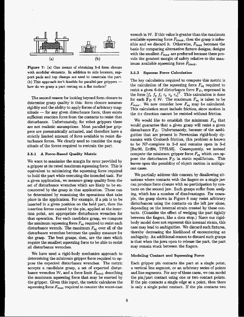
Figure 7: (a) One means of obtaining 3-d form closure with modular elements. In addition to side locators, sup- port pads and top clamps are used to constrain the part. (b) This approach isn’t feasible for parallel-jaw grippers - how do we grasp a part resting on a flat surface?
The second reason for looking beyond form closure to determine grasp quality is this: form closure assumes rigidity and the ability to apply forces of arbitrary mag- nitude - for any given disturbance force, there exists sufficient reaction force from the contacts to resist that disturbance. Unfortunately, for robot grippers these are not realistic assumptions. Most parallel-jaw grip- pers are pneumatically actuated, and therefore have a strictly limited amount of force available to resist dis- turbance forces. We clearly need to consider the mag- nitude of the forces required to restrain the part.
3.5.1 A Force-Based Quality Metric
We want to maximize the margin for error provided by a gripper at its rated maximum squeezing force. This is equivalent to minimizing the squeezing force required to hold the part while executing the intended task. For a given application, we measure grasp quality from the set of disturbance wrenches which are likely to be en- countered by the grasp in that application. These can be determined by examining the operations that take place in the application. For example, if a pin is to be inserted in a given position on the held part, then the insertion forces caused by the pin, applied at the inser- tion point, are appropriate disturbance wrenches for that operation. For each candidate grasp, we compute the minimum squeezing force F,, required to resist each disturbance wrench. The maximum F,, over all of the disturbance wrenches becomes the quality measure for the grasp. The best grasps, then, are the ones which require the smallest squeezing force to be able to resist all disturbance wrenches.
We have used a rigid-body mechanics approach to determining the minimum gripper force required to op- pose the expected disturbance wrenches. The metric accepts a candidate grasp, a set of expected distur- bance wrenches W , and a force limit F1inzit describing the maximum squeezing force that may be exerted by the gripper. Given this input, the metric calculates the squeezing force F,,, required to counter the worst-case
wrench in W . If this value is greater than the maximum available squeezing force Flimit, then the grasp is infea- sible and we discard it. Otherwise, F,,, becomes the basis for comparing alternative fixture designs; designs with the smallest F,,, are preferred because these pro- vide the greatest margin of safety relative to the max- imum available squeezing force Flimit.
3.5.2 Squeeze Force Calculation
The key calculation required to compute this metric is the calculation of the squeezing force Fsq required to resist a given 6-dof disturbance force FD, expressed in the form [f, fy fi T, T~ T , ] ~ . This calculation is done for each FD E W . The maximum F,, is taken to be F,,,. We now consider how Fsq may be calculated. This calculation must include friction, since motion in the fz direction cannot be resisted without friction.
We would like to establish the minimum F,, that would guarantee that a given grasp will resist a given disturbance FD. Unfortunately, because of the ambi- guities that are present in Newtonian rigid-body dy- namics with Coulomb friction, this problem is known to be NP-complete in 2-d and remains open in 3-d fBar90, Erd94, TPSL951. Consequently, we instead compute the minimum gripper force F,, which can op- pose the disturbance FD in static equilibrium. This leaves open the possiblity of object motion in ambigu- ous cases.
We partially address this concern by disallowing sit- uations where contacts with the fingers on a single jaw can produce force closure with no participation by con- tacts on the second jaw. Such grasps suffer from wedg- ing, which has a number of disadvantages. For exam- ple, the grasp shown in Figure 8 may resist arbitrary disturbances using the contacts on the left jaw alone, depending on the internal strain created by these con- tacts. (Consider the effect of wedging the part tightly between the fingers, like a door stop.) Since our rigid- body model does not represent this internal strain, this case may lead to ambiguities. We discard such fixtures, thereby decreasing the likelihood of encountering an ambiguity. An additional reason to discard such grasps is that when the jaws open to release the part, the part may remain stuck between the fingers.
Modeling Contact and Squeezing Force
Each gripper pin contacts the part at a single point, a vertical line segment, or an arbitrary series of points and line segments. For any of these cases, we can model the pin/part contact using one or two contact points. If the pin contacts a single edge at a point, then there is only a single point contact. If the pin contacts two
8
I-
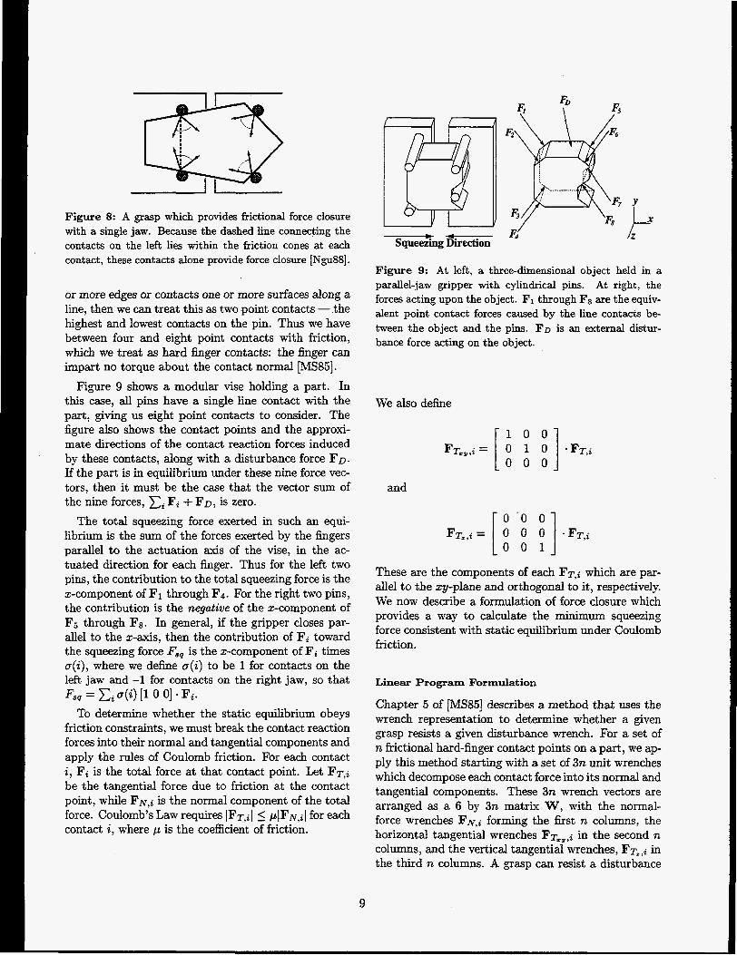
Figure S: A grasp which provides frictional force closure with a single jaw. Because the dashed line connecting the contacts on the left lies within the friction cones at each contact, these contacts alone provide force closure [Ngu88].
or more edges or contacts one or more surfaces along a line, then we can treat this as two point contacts - the highest and lowest contacts on the pin. Thus we have between four and eight point contacts with friction, which we treat as hard finger contacts: the finger can impart no torque about the contact normal [MS85].
Figure 9 shows a modular vise holding a part. In this case, all pins have a single line contact with the part, giving us eight point contacts to consider. The figure also shows the contact points and the approxi- mate directions of the contact reaction forces induced by these contacts, along with a disturbance force FD. If the part is in equilibrium under these nine force vec- tors, then it must be the case that the vector sum of the nine forces, Ci Fi + FD, is zero.
The total squeezing force exerted in such an equi- librium is the sum of the forces exerted by the fingers parallel to the actuation axis of the vise, in the ac- tuated direction for each finger. Thus for the left two pins, the contribution to the total squeezing force is the x-component of F1 through Fq. For the right two pins, the contribution is the negative of the x-component of F5 through F g . In general, if the gripper closes par- d e l to the x-axis, then the contribution of Fi toward the squeezing force Fsp is the x-component of Fi times o(i), where we define a(i) to be 1 for contacts on the left jaw and -1 for contacts on the right jaw, so that
To determine whether the static equilibrium obeys friction constraints, we must break the contact reaction forces into their normal and tangential components and apply the rules of Coulomb friction. For each contact i, Fi is the total force at that contact point. Let FT,~ be the tangential force due to friction at the contact point, while F N , ~ is the normal component of the total force. Coulomb’s Law requires IFT,~ I 5 pIF~,il for each contact i, where p is the coefficient of friction.
Fsq = xi ~ ( i ) [l 0 01 - Fi.
9
&’ k Figure 9: At left, a three-dimensional object held in a parallel-jaw gripper with cylindrical pins. At right, the forces acting upon the object. F1 through Fs are the equiv- alent point contact forces caused by the line contacts be- tween the object and the pins. FD is an external distur- bance force acting on the object.
We also define
. FT,i
These are the components of each FT,i which are par- allel to the zy-plane and orthogonal to it, respectively. We now describe a formulation of force closure which provides a way to calculate the minimum squeezing force consistent with static equilibrium under Coulomb friction.
Linear Program Formulation
Chapter 5 of [MS85] describes a method that uses the wrench representation to determine whether a given grasp resists a given disturbance wrench. For a set of n frictional hard-finger contact points on a part, we ap- ply this method starting with a set of 3n unit wrenches which decompose each contact force into its normal and tangential components. These 3n wrench vectors are arranged as a 6 by 3n matrix W, with the normal- force wrenches FN,~ forming the first n columns, the horizontal tangential wrenches FT,,,~ in the second n columns, and the vertical tangential wrenches, FT,,~ in the third n columns. A grasp can resist a disturbance

wrench FD if there exists a 3n-element vector of con- tact wrench magnitudes c, such that:
W c + F o = O ,
0 The first n elements of c are positive (a contact can push but not pull), and
The magnitudes of the tangential-force wrenches at each contact do not exceed /I times the magni- tude of the normal-force wrench.
We can then formulate the minimum squeezing force problem as an optimization problem, where we want to minimize Fsq given the above conditions. Unfortu- nately, the third condition is nonlinear, since it requires computing the magnitude of FT,~. Since we don’t have a general method for solving nonlinear optimization problems, we linearize the problem using the method proposed by Trinkle, et al [TPSL95]: Instead of re- stricting the magnitude of the total tangential force to no more than p times the normal force, we restrict each of FT,,,~ and FT,,~ to be no more than 5 times the normal force. Thus, instead of restricting the contact force to lie in a circular cone, we restrict the force to lie in a square pyramid inscribed inside the circular cone.
This approximation allows us to write the following linear program:
minimize
where p’ = J& and i E [l,n], where n is the num- ber of contact points. Condition 1 ensures that static equilibrium is possible. Condition 2 ensures that each contact normal force is non-negative, and conditions 3-4 ensure that the total contact force lies within the friction pyramid. Solving this h e a r program identifies the minimum squeezing force for which the system can maintain static equilibrium while obeying our approx- imated friction constraints.
We repeat this for all expected disturbance forces and take the maximum to obtain the desired worst- case required squeezing force F,,, .
10
3.6 Inter-Gripper Interference Analysis
Another type of analysis which our tool provides is inter-gripper interference analysis. This is useful in situations where there is a gripper mounted on a robot arm which is placing a part in a stationary modular vise fixture, or removing a part from such a fixture. Such a situation might arise in manufacturing applica- tions when it is necessary to automatically refixture a part so that new features can be exposed for machm- ing, assembly, or cleaning operations. This analysis is performed on existing grasp designs, and returns all pairs of grasps with which the part can be handed &om one grasp to the other without interference between the fingers of the two grippers.
The analysis is performed after grasp designs are generated, filtered, and sorted for quality. We assume that the two sets of grasps are generated from oppc- site sides of the part. This means that the features against which pins are placed in the two sets of grasps may be different, but more importantly means that there is a reflection across the y-axis in the informa- tion passed to the 2-d fixture generation algorithm. To determine whether a pair of grasps is compatible, we check for (i) interference between the pins when both grippers are closed, (ii) interference between the pins when the first gripper opens or closes, and (iii) interfer- ence between the pins when the second gripper opens or closes. If no interference is found, then the part may be handed off from one grasp to the other. An example of this analysis is shown in the next section.
subject to
1: Wc+Fo=O
4 Applications
4.1 Part Handling for the Automated Component Cleaning Workcell
The Automated Component Cleaning project is an initiative within Sandia’s Intelligent Systems and Robotics Center to design a workcell capable of per- forming flexible, high-quality cleaning of machined parts using an environmentally benign alcohol spray. The workcell uses a six degree-of-freedom robot arm equipped with a focused spray-nozzle to clean the parts, using an automatically formulated spraying mo- tion to clean machine oil and similar impurities out of holes and concavities on the part.

Figure 10: The ACC workcell: 1. the airlock. 2. the pallet. 3. the arm’s linear track. 4. the arm’s rotational actuator. 5. the arm gripper. 6. the pedestal gripper. 7. the 6-dof sprayer arm. 8. the spray nozzle.
The process is the following:
a. The part enters the workcell.
b. The exposed features on the part are cleaned with a high pressure spray.
c. The part is flipped over so that previously oc- cluded features become exposed.
d. The flip side of the part is cleaned.
e. The part exits the workcell.
Figure 10 shows a model of the workcell and its part- handling hardware. Because the cleaning spray is a flammable alcohol solution, the workcell is kept under a positive pressure nitrogen atmosphere. For this reason, the workcell is equipped with an airlock, through which
a part enters on a pallet. Once the part is in the airlock, a two degree of freedom arm (a linear actuator and one degree of rotational actuation) with a parallel-jaw gripper extracts the part from the pallet and carries it into the workcell. Before spraying begins, a pedestal- mounted gripper closes onto the part and the 2-dof arm releases the part. After releasing the part, the 2- dof arm rotates 180 degrees to avoid interfering with the cleaning process. After the first cleaning operation has been accomplished, the 2-dof arm rotates back into place and reacquires the part. The pedestal gripper releases the part, and then the 2-dof arm rotates 180 degrees again, so that the part is sitting above the arm gripper. At this time, the second half of the cleaning operation takes place. After cleaning is completed, the 2-dof arm rotates back to its original position, carries the part into the airlock, and places it back on the pallet. The arm then retracts, and the part can then be
11

Figure 11: The ACC pedestal and arm grippers. (a) The pedestal gripper holding the part. (b) The handoff. (c) The arm rotated 180 degrees, holding the part.
removed from the airlock. Figure 11 shows a detailed view of the arm/pedestal handoff.
To allow the workcell to handle a variety of parts, the arm and pedestal grippers are each configured as a modular vise. The pallet is configured as one-half of a modular vise; since the part rests on the flat surface of the pallet, the pallet must locate the part but does not need to grip it. Note that in order to allow these devices to grasp and hand off arbitrary parts, their relative positions must be adjustable. Thus the the arm gripper can be adjusted in 0, while the pedestal gripper can be adjusted in 5 and y. Similarly, the pallet is adjustable in 2, y, and 0.
We developed a design program which allows the user t o configure the workcell grippers and pallet to handle an arbitrary part, subject to the limitations of the workcell hardware. The program begins by gen- erating candidate grasps for the arm gripper, pedestal
. . . . . . . . . . . . 3 .
. I * . . . . . , .. . . . . . . . . . . ......................................................... ...............+... I :""" . . .-.
(a)
. . . . . . . . . . - . - : . ......................................................................
. . .
. . . .
Figure 12: Top views of the ACC grippers. The "race- track" shapes show the paths followed by fingers on the other grippers during a handoff. (a) The arm gripper, with the pallet (dashed) and pedestal finger paths shown. (b) The pedestal gripper, with the arm finger paths shown. (c) The pallet, also with the arm finger paths shown. This interference-free grasp triple was automatically generated by the design tool.
12

Figure 13: The ACC grippers holding the valve housing. (a) The arm gripper. (b) The pedestal gripper. (c) Both grippers simultaneously holding the part.
Figure 14: A closeup of the physical ACC grippers. (a) The arm gripper. (b) The pedestal gripper. and (c) Both grippers simultaneously holding the part. The pin lengths were extended to allow spray clearance from low angles.
13

gripper, and pallet. Since the part “up” orientation is the same for the pallet and pedestal gripper, the al- gorithm produces pallet designs by simply taking all pedestal gripper designs that have three fingers on one jaw, and ignoring the single finger on the other jaw.
The program then generates triples of grasps which will successfully handle the part. We use the inter- gripper interference analysis described in Section 3.6 to ensure that the grasps for the arrn and the pallet are compatible and also that the grasps for the arm and the pedestal are compatible. This produces a series of compatible (arm, pallet ) and (arm,pedes ta l ) grasp pairs. A join operation is then used to generate all triples where the arm is compatible with both the pal- let and the pedestal. “Join” is a set operator from re- lational databases; in this case, it produces all 3-tuples (arm,pedestal,pallet) for which (arm,pedes ta l ) and (arm,palZet) are pairs of noninterfering grasps.
Figures 12-14 show an example grasp triple found by our code. A study of Figure 12 confirms that there is no interference between the gripper fingers during handoffs. Physical tests with the hardware verified that these grippers successfully hold the part during spray operations, and also that the handoff operation works properly.
To assist the user in selecting the best triple, our program ranks the triples by minimizing the maximum squeeze force required by the arm or pedestal grasps to resist the expected disturbances. The next section explains how these disturbance forces were estimated.
Disturbance Force Calculations
Two types of disturbances act on a part in the ACC workcell: contact forces exerted during spray cleaning, and inertial forces exerted during arm motion.
When the cleaning spray hits the part, it exerts a force on the part at the point of contact. We can esti- mate the magnitude of this force as follows: Based on the manufacturer’s specifications of the spray nozzle, the nozzle aperture is 1.2mm diameter, and produces a flow of 0.07- at 5OOpsi. A flow of 0.07- through a 1.2mm diameter aperture gives a flow velocity of 62% (flow velocity = volume per unit time / area). Further, 0.07% at a density of 1 - 0 5 gives a mass flow rate of 0 .072 (mass flow = volume flow x density). Since the imparted force = flow velocity x mass flow [HR81], the force of the spray exiting the nozzle is 4.2N, just under one pound. A conservative model of the force ex- perienced by the part is to neglect aerodynamic drag and assume that the part reverses this flow, doubling the force. Thus, we use a value of 8.4N for the force exerted on the part by the spray.
Figure 15: The disturbance forces used for the gripper squeeze force analysis.
This is the magnitude of the force exerted on the part at a particular instant in the cleaning process, when the cleaning spray hits a specific point on the part surface. To characterize the set of forces exerted on the part over the entire cleaning process, we gen- erate a large number of random 8.4N forces, taking care to get a decent sampling of force directions and positions. We then determine where that force f i s t in- tersects the part, and erect an 8.4N force at that inter- section point, normal to the surface. A more accurate force characterization could be obtained by simulating the cleaning operation in detail, but we chose not to use this method because of its computational expense.
There are two types of arm transfer motions: A lii- ear motion when the part is moved in and out of the airlock, and a rotational motion when the part is swung into the inverted position. The linear motion is very slow, so its accelerations are negligible. For the ro- tational motion, the largest accelerations occur when the arm hits its motion stops. Accelerometer mea- surements indicated that the peak acceleration is 6g ( 5 9 s ) . Since the mass of the example part is 0.18kg, the maximum disturbance force is 11N, acting on the centroid of the part in the fz direction.
Figure 15 shows the set of forces used for the grip- per squeeze force analysis. Given a measured fric- tion coefficient of 0.2, the worst-case squeezing force required to resist these disturbances is 77N for the arm grasp shown in Figures 13-14, and 39N for the pedestal grasp, which does not incur the 11N acceler- ation. The maximum squeeze force capacity of each gripper is 140N.
14
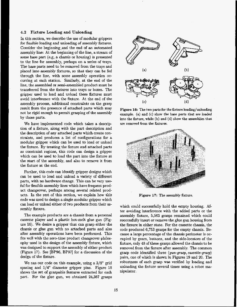
4.2 Fixture Loading and Unloading In this section, we describe the use of modular grippers for flexible loading and unloading of assembly fixtures. Consider the beginning.and the end of an automated assembly line: At the beginning of the l i e , a stream of some base part (e.g, a chassis or housing) is presented to the line for assembly, perhaps on a series of trays. The base parts need to be removed from the trays and placed into assembly fixtures, so that they can be fed through the line, with some assembly operation oc- curring at each station. Similarly, at the end of the line, the assembled or semi-assembled product must be transferred from the fixtures into trays or boxes. The gripper used to load and unload these fixtures must avoid interference with the fixture. At the end of the assembly process, additional constraints on the grasp result from the presence of attached parts which may not be rigid enough to permit grasping of the assembly by those parts.
We have implemented code which takes a descrip- tion of a fixture, along with the part description and the description of any attached parts which create con- straints, and produces a list of configurations for a modular gripper which can be used to load or unload the fixture. By treating the fixture and attached parts as constraint regions, this code can design a gripper which can be used to load the part into the fixture at the start of the assembly, and also to remove it from the fixture at the end.
Further, this code can identify gripper designs which can be used to load and unload a variety of different parts, with no hardware change. This can be very use- ful for flexible assembly lines which have frequent prod- uct changeover, perhaps among several related prod- ucts. In the rest of this section, we explain how this code was used to design a single modular gripper which can load or unload either of two products from their as- sembly fixture.
The example products are a chassis from a personal cassette player and a plastic hot-melt glue gun (Fig- ure 16). We desire a gripper that can grasp either the chassis or glue gun with no attached parts and also after assembly operations have been performed. This fits well with the zero-time product changeover philos- ophy used in the design of the assembly fixture, which was designed to support the assembly of either product (Figure 17). See [BP96, BP971 for a discussion of the design of the fixture.
We ran our code on this example, using a 3/8” grid spacing and 1/4” diameter gripper pins. Figure 18 shows the set of graspable features extracted for each part. For the glue gun, we obtained 24,367 grasps
Figure 16: The two parts for the fixture loading/unloading example. (a) and (c) show the base parts that are loaded into the fixture, while (b) and (d) show the assemblies that are removed from the fixtures.
Figure 17: The assembly fixture.
which could successfully hold the empty housing. Af- ter avoiding interference with the added parts or the assembly fixture, 5,563 grasps remained which could successfully insert or remove the glue gun housing from the fixture in either state. For the cassette chassis, the code produced 6,753 grasps for the empty chassis. Be- cause a large percentage of the chassis perimeter is oc- cupied by gears, buttons, and the side-locators of the Gxture, only 48 of these grasps allowed the chassis to be removed from the fixture after assembly. The common grasp code identified three (gun-grasp, cassette-grasp) pairs, one of which is shown in Figures 19 and 20. The robustness of each grasp was verified by loading and unloading the fixture several times using a robot ma- nipulator.
15

6' - JL
(c) ( 4
Figure 18: The extracted features for the glue gun and cassette chassis examples: (a) and (c) show the features ex- tracted from the base parts. (b) and (d) show the features extracted from the populated assemblies sitting in their as- sembly fixtures. The small circles at the part boundaries represent the sidelocating pins on the fixtures; similar cir- cles within the part boundaries are the vertical support pads.
(b)
Figure 20: The physical gripper for the glue gun and the cassette chassis, shown loading the assembly pallet. The gripper is attached to an Adept One manipulator, whose base is visible in the background.
Figure 19: The common gripper for the gluegun and the cassette chassis. The views shown are in the gripper kame of reference, as though seen through transparent plates. The small open circles are the pins of the assembly fixture.
16

5 Conclusion
The algorithms described in this paper extend Wal- lack and Canny’s planar modular vise algorithm to 3-d. Our code accepts 3-d CAD models as input and out- puts 3-d gripper designs. Loadability analysis ensures that the returned grasps can be easily achieved. We have added a force analysis that takes a gripper design and a set of expected disturbance forces and returns the minimum squeeze force that can oppose all of the expected disturbances. To quickly find the best grasps, we rank them using this minimum squeeze force. We also implemented inter-gripper interference algorithms to analyze grasp handoffs.
We have applied our code to two examples. In the first example, we used the code to design triples of non-interfering grasps for the Sandia Automated Com- ponent Cleaning workcell. In the second example, we used the code to design a gripper for loading and un- loading assembly fixtures on a mixed-product assembly line. We performed physical tests to verify the success of the resulting designs in both cases.
In the course of this research, we’ve spent substantial time considering the possibilities offered by modular parallel-jaw grippers, and also talking with automation engineers from industry. The biggest reaction we’ve had from our industrial contacts is concern about the cylindrical gripper fingers. The problem is primarily one of synthesizing grippers that do not interfere with the surrounding assembly during insertion operations. In many cases, it is impossible to select a diameter of cylindrical finger which will provide sufficient rigidity while avoiding interference during the insertion. Pos- sible solutions to this problem might involve the use of an expanded set of finger primitives, such as families of flat, circular arc, or angled corner pieces.
Another limitation on both the analysis we have per- formed and the possibilities offered by the algorithm is that we assume that a part being grasped contacts only the fingers of the gripper, and only has contact with vertical surfaces on the fingers. While we have already observed that it is not feasible to use horizontal con- tacts to completely constrain the part, it is reasonable to use them to add stability. For example, we could equip the fingers with shoulders that can oppose distur- bance forces with a significant component directed to- ward the palm of the gripper. Another approach would be to allow the part to contact the palm of the gripper. Extending the synthesis and force analysis algorithms to handle these additional contacts would be relatively straightforward.
Unfortunately, including these additional contacts
significantly complicates the problem of robustly ac- quiring the part. Given real, imperfect manipulators, it is not possible to exactly match the z heights of the gripper and part during the grasping motion, and the resulting misalignment could cause problems when the fingers close. Solving this problem requires some form of compliant grasping strategy. One possible strat- egy would be to (i) Position the gripper over the part, above the final z height, (ii) Apply a small squeezing force which closes the jaws on the part without apply- ing significant holding force, (iii) Apply a downward force, so that the horizontal shoulders of the pins or gripper palm slide into contact with the part, and fi- nally (iv) Tighten the jaws completely, ensuring a se- cure grasp. It may be possible to implement this or other strategies with a passive mechanism attached to the gripper.
6 Acknowledgements
We thank Aaron Wallack for providing his planar fix- ture design code, and Ralph Peters and Randy Wil- son for their comments on a draft of this paper. We thank Ron Simon for fabricating the gripper hardware, and Gilbert Benavides and Lilita Meirans for their help developing the ACC example. ACIS@ is a registered trademark of Spatial Technologies.
References [AB851
[Bar901
[BG96]
[Bic95]
[BP96]
[BP9?]
H. Asada and A. B. By. Kinematic analysis of workpart h tur ing for flexible assembly with au- tomatically reconfigurable fixtures. IEEE Jour- nal of Robotics and Automation, RA-1(2):86-94, June 1985.
D. Bar&. Determining frictional inconsistency for rigid bodies is npcomplete. Technical Report TR 90-1112, Cornel1 University Department of Computer Science, April 1990.
R. C. Brost and K. Y. Goldberg. A com- plete algorithm for designing planar fixtures us- ing modular components. IEEE !i!ransactions on Robotics and Automation, 12(1):31-46, February 1996.
A. Bicchi. On the closure properties of robotic grasping. International Journal of Robotics Re- search, 14(4):319-334, August 1995.
R. C. Brost and R. R. Peters. Automatic de- sign of 3-d fixtures and assembly pallets. In Proceedings, IEEE International Conference on Robotics and Automation, pages 495-502, April 1996.
R. C. Brost and R. R. Peters. Automatic design of 3-d ftrtures and assembly pallets. Technical
17
[Eng871
[Erd94]
[GHM89]
[HaySol
[KR811
[Kim931
[KRw
[Lak78]
[MD89]
[Met931
Report SAND 95-2411, Sandia National Labora- tories, January 1997.
P. J. Englert. Principles for Part Setup and Workholding in Automated Manufacturing. PhD thesis, Carnegie Mellon University Department of Mechanical Engineering, December 1987.
M. Erdmann. On a representation of friction in configuration space. International Journal of Robotics Research, 13(3):240-271, June 1994.
R. A. Grupen, T. C. Henderson, and I. D. MC- Cammon. A survey of general purpose manipula- tion. International Journal of Robotics Research, 8(1):38-62, February 1989.
C. C. Hayes. Machining Planning: A Model of an Expert Level Planning Process. PhD thesis, Carnegie Mellon University Robotics Institute, December 1990.
D. Halliday and R. Resnick. Fundamentals of Physics, 2nd Ed. John Wiley and Sons, New York, 1981. Page 144.
K. H. Kim. A System for Automated Fidure Planning with Modular Fixtures. PhD thesis, Carnegie Mellon University Robotics Institute, May 1993.
J. Kerr and B. Roth. Analysis of multifingered hands. International Journal of Robotics Re- search, 4(4):3-17, Winter 1986.
K. Lakshminarayana. The mechanics of form closure. Technical Report 78-DET-32, ASME, 1978.
R. J. Menassa and W. R. DeVries. Locating point synthesis in fixture design. Annals of the
E. C. De Meter. Restraint analysis of assembly work carriers. Robotics and Computer Integrated Manufacturing, 10(4):257-265, 1993.
CIRP, 38(1):165-169, 1989.
[Pon96]
[PT89]
[Reu76]
[Sal821
[SomOO]
[TPSL95]
[Trig21
WC94
~ ~ 9 6 1
J. Ponce. On planning immobilizing fixtures for three dimensional parts. In Proceedings, IEEE International Conference on Robotics and Au- tomation, pages 509-514, April 1996.
J. Pertin-Troccaz. Grasping: A state of the art. In 0. Khatib, J. J. Craig, and T. Lozano- PCrez, editors, The Robotics Review I, pages 71- 98. MIT Press, Cambridge, Massachusetts, 1989.
F. Reuleaux. The Kznematics of Machinery. Macmillan, 1876. Republished by Dover, New York, 1963.
J. K. Salisbury. Kinematic and Force Analysis of Articulated Hands. PhD thesis, Stanford Uni- versity Department of Mechanical Engineering, May 1982. Reprinted in Robot Hands and the Mechanics of Manipulation, MIT Press, Cam- bridge, Massachusetts, 1985.
P. Somoff. Uber gebiete von schraubengeschwin- digkeiten eines festen korpers bei verschiedener zal von stutzflachen. Zeitschrift f i r Mathematik und Physik, 45:245-306, 1900.
J. C. Trinkle, J-S. Pang, S. Sudarsky, and G. Lo. On dynamic multi-rigid-body contact problems with coulomb friction. Technical Report 95-003, Texas A&M University Department of Com- puter Science, January 1995.
J. C. Trinkle. A quantitative test for form closure grasps. In Proceedings, IEEE/RSJ International Conference on Intelligent Robots and Systems, pages 1670-1677, July 1992.
A. S. Wallack and J. F. Canny. Planning for modular and hybrid fixtures. In Proceedings, IEEE International Conference on Robotics and Automation, pages 520-527, May 1994.
A. S. Wdack and J. F. Canny. Modular fixture design for generalized polyhedra. In Proceedings, IEEE International Conference o n Robotics and Automation, pages 830-837, April 1996.
[MNPSO] X. Markenscoff, L. Ni, and C. H. Papadimitriou. The geometry of grasping. International Journal of Robotics Research, 9(1):61-74, February 1990.
Matthew T. Mason and J. Kenneth Salisbury. Robot Hands and the Mechanics of Manipula- tion. MIT Press, Cambridge, Massachusetts, 1985.
B. Mishra, J. T. Schwartz, and M. Sharir. On the existence and synthesis of multifinger posi- tive grips. Algorithmica, 2(4):641-558, 1987.
[Ngu88] V. Nguyen. Constructing force-closure grasps. International Journal of Robotics Research, 7(3):3-16, June 1988.
V. Nguyen. Constructing stable grasps. Interna- tional Journal of Robotics Research, 8(1):26-37, February 1989.
[MS85]
[MSS87]
[Ngu89]
18

Distribution:
MS 9018 Central Technical FIles, 8940-2 0899 Technical Library, 4414 0619 Review & Approval Desk, 12630
For DOE/OSTI