Embed Size (px)
Citation preview
INTERNATIONAL JOURNAL OF ENERGY RESEARCHInt. J. Energy Res. 2004; 28:1127–1144Published online 19 July 2004 in Wiley InterScience (www.interscience.wiley.com). DOI: 10.1002/er.1019
A modern injected steam gas turbine cogeneration systembased on exergy concept
Mohammed Ghiyath Soufin,y, Terushige Fujii and Katsumi Sugimoto
Kobe University, Faculty of Engineering, 1-1 Rokkodai-cho, Nada-ku, Kobe shi 657-8501, Kobe, Japan
SUMMARY
Factors such as low capital cost, good match of power and heat requirements and proven reliability cansometimes lead an end user into purchasing gas turbines for use in a modern cogeneration plant. Thesteam-injected gas turbine is an attractive electrical generating technology for mitigating the impacts ofrising energy prices.According to such mentioned above this paper is to provide results of an optimization study on
cogeneration power cycle, which works by gas turbine with recuperator and injection steam added to thecombustor of the gas turbine. The performance characteristics of the cycle based on energy and exergyconcepts and based upon practical performance constraints were investigated. The effect of the recuperatoron the cycle was greatly clarified. Results also show that the output power of a gas turbine increases whensteam is injected. When extra steam has to be generated in order to be able to inject steam and at the sametime to provide for a given heat demand, power generating efficiency increases but cogeneration efficiencydecreases with the increasing of injected steam. Copyright # 2004 John Wiley & Sons, Ltd.
KEYWORDS: exergy analysis; thermodynamics; cogeneration system; thermal efficiency; gas turbine cycle;performance characteristics
1. INTRODUCTION
The technology greatly extends the range of cost-effective gas turbine cogeneration to includemany applications that involve variable and unpredictable process steam load. The highefficiency of this technology makes it possible to produce electric power competitively and withlow environmental impacts when fired with natural gas and relatively costly synthetic fuels.Furthermore, in order to meet the needs of the variation of the electric power-heat ratio utilityin cogeneration industry and of the decrease of the NOx, the steam-injected gas turbines areconsidered, which are called the Cheng cycle. Steam-injected gas turbine cogeneration plant(referred to as SIGTC below) is potentially attractive alternative technology which meetscurrent utility needs. The technology involves a variation of the simple cycle gas turbine whereinsteam is generated in a heat recovery steam generator (HRSG), using the turbine waste heat.This steam is then injected into the gas turbine to augment the power output and significantly
Received 12 December 2002Accepted 5 November 2003Copyright # 2004 John Wiley & Sons, Ltd.
yE-mail: [email protected]
nCorrespondence to: M. G. Soufi, Kobe University, Faculty of Engineering, 1-1 Rokkodai-cho, Nada-ku,Kobe shi 657-8501, Kobe, Japan.
enhance the cycle efficiency. Steam injected to the gas turbine is an attractive way to control theNOx and clean uprating of the exhausted hot gases. Additionally, the SIGTC has numerousadvantages, including: wide capacity range, low cost, low heat rate, short lead time, minimumfield construction, planning flexibility, ease of operation and reliability (low maintenance). Inthe last 20 years some good papers have studied a such cycle, like Sue (1995), De Paepe, andDick (2000), Baken (1988), Little (1988), Westsik (1987), Cain (1988, 1989), Kaempffer (1989),Larson (1986), Wilhelmsson (1980), and some of them have studied the cycle by practicalanalysis Sue (1995), De Paepe and Dick (2000) and the others by theoretical analysis (Baken,1988; Little, 1988; Westsik, 1987) in order to describe the advantages of this cycle. However, thestudy of Sue (1995) from (Kawasaki) was with more realization of practical results applied onthe field. My study in this paper actually is a continuation of the previous studies (Soufi (2002,2003)) especially of the study of Sue (1995) and an attempt to cope and realize the exergitictheoretical investigation analysis of the cycle to be applied practically on the gas turbinecogeneration power plant according to the recent advanced high-quality gas turbines using incogeneration power plant. The highlight of this work is that this paper could optimize twoadvanced studies: the first is to increase the efficiency and power output of the SIGTC cyclemore than the other previous adapted papers. And the second it is to influence the recuperatorinto the cycle to optimize the distribution of the thermal load between the recuperator and thewaste-heat boiler. Recovering waste heat from the high-temperature exhaust gas of a gas turbineis a means of improving the cycle efficiency. In this power plant an air preheater, that is arecuperator, extracts energy from the exhausted gases to heat the combustion air. Heatexchangers or regenerator for gas turbines are of the same type, i.e. tubular or rotary-plate. As atarget of gas turbine unit in a cogeneration power plant (30MW) Kawasaki’s gas turbine wasinvestigated (Hyprotech, 2000).
2. STEAM-INJECTED GAS TURBINE TECHNOLOGY AND FEATURES
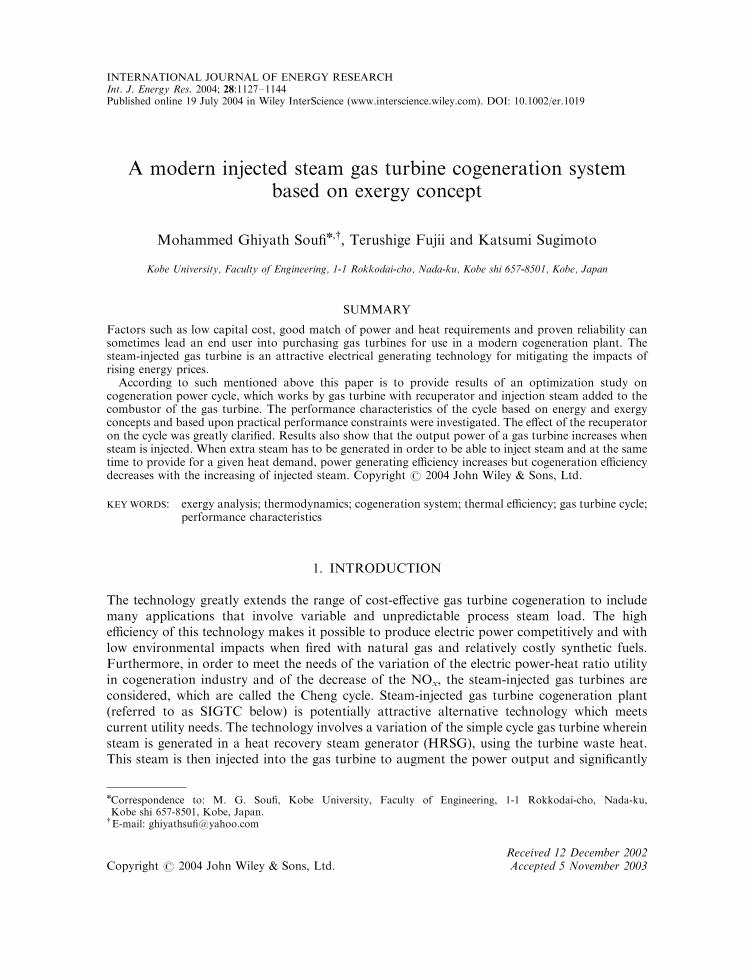
Steam injection gas turbines are two typesType 1 (Figure 1): Airflow rate of compressor: Constant (Gas flow rate of turbine: Increase).
* Turbine inlet pressure P3 can be obtained by Stodola’s ellipse formula
ðGm=GgÞ2 ¼ ðP 2
3 � P 24 Þ=ðP
23O � P 2
4 Þ ð1Þ
For example, owing to 10% steam injection of turbine flow rate, the pressure ratio p:15 of gasturbine changes to p:16.3 as shown in Table I.
* If the quantity of injected steam is always constant, the pressure ratio p will not change byadoption of 10% larger gas flow area turbine. However, the method mentioned aboverequires another new design gas turbine. Moreover, it is impossible to cope with injectedsteam alternation. In general, steam injected gas turbine is used by alternation, or in therange of balance allowance of compressor and turbine.
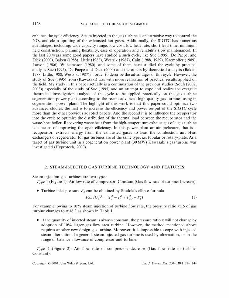
Type 2 (Figure 2): Air flow rate of compressor: decrease (Gas flow rate in turbine:Constant).
Copyright # 2004 John Wiley & Sons, Ltd. Int. J. Energy Res. 2004; 28:1127–1144
M. G. SOUFI, T. FUJII AND K. SUGIMOTO1128
The compressor suction fairflow is decreased by the quantity equivalent to injected steamflow. (Decrease of suction airflow rate is carried out by throttle of inlet guide vane andinclination of static blades angle.)
Required compressor power becomes smaller owing to the decrease of airflow rate by:
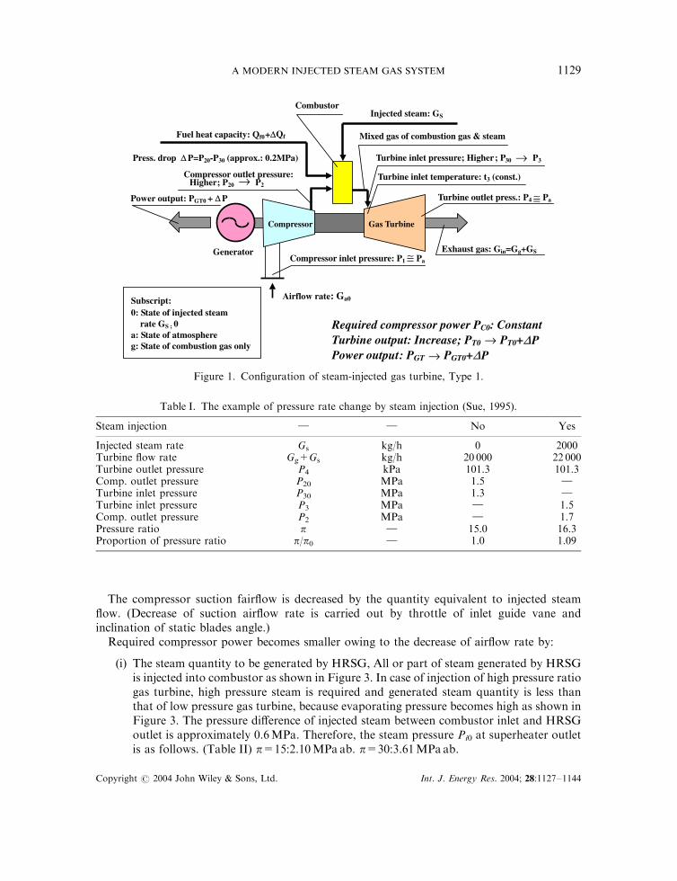
(i) The steam quantity to be generated by HRSG, All or part of steam generated by HRSGis injected into combustor as shown in Figure 3. In case of injection of high pressure ratiogas turbine, high pressure steam is required and generated steam quantity is less thanthat of low pressure gas turbine, because evaporating pressure becomes high as shown inFigure 3. The pressure difference of injected steam between combustor inlet and HRSGoutlet is approximately 0.6MPa. Therefore, the steam pressure Pi0 at superheater outletis as follows. (Table II) p=15:2.10MPa ab. p=30:3.61MPa ab.
Turbine outlet press.: P4 ≅ Pa Power output: PGT0 + ∆∆ P
Turbine inlet pressure; Higher; P30 P3
Mixed gas of combustion gas & steam
Injected steam: GS
Combustor
Fuel heat capacity: Qf0+∆Qf
Press. drop ∆ P=P20-P30 (approx.: 0.2MPa)
Compressor outlet pressure:Higher ; P20 P2
Compressor inlet pressure: P1 ≅ Pa
Exhaust gas: Gin=Gg+GS
Turbine inlet temperature: t3 (const.)
Airflow rate: Ga0
Required compressor power PC0: ConstantTurbine output: Increase; PT0 PT0+∆P Power output : PGT PGT0+∆P
Gas Turbine Compressor
Generator
Subscript: 0: State of injected steam
rate GS ; 0 a: State of atmosphereg: State of combustion gas only
→
→→
→
Figure 1. Configuration of steam-injected gas turbine, Type 1.
Table I. The example of pressure rate change by steam injection (Sue, 1995).
Steam injection } } No Yes
Injected steam rate Gs kg/h 0 2000Turbine flow rate Gg+Gs kg/h 20 000 22 000Turbine outlet pressure P4 kPa 101.3 101.3Comp. outlet pressure P20 MPa 1.5 }Turbine inlet pressure P30 MPa 1.3 }Turbine inlet pressure P3 MPa } 1.5Comp. outlet pressure P2 MPa } 1.7Pressure ratio p } 15.0 16.3Proportion of pressure ratio p/p0 } 1.0 1.09
Copyright # 2004 John Wiley & Sons, Ltd. Int. J. Energy Res. 2004; 28:1127–1144
A MODERN INJECTED STEAM GAS SYSTEM 1129
(ii) The limitation is due to compressor performance characteristics. The maximum injected steamquantity is in fact, not the HRSG generated steam rate mentioned above but compressorperformance characteristics which are independent of individual ones. Figure 4 is the exampleof the compressor characteristics of one of 30MW Mitsubishi Kawasaki’s gas turbines. Theslim actual line is the surge line and the dot line is the surge protect line. Based on Figure 1 weexplain the state of steam injection. The state of no steam injection is the point Dp.
Power output: PGT0 +∆∆P Turbine outlet press.: P4 Pa
Required compressor power:Decrease;PC0 PC0 -∆PC
Turbine output: PT0 : Constant Power output : PGT PGT0+∆P
Exhaust gas :Gin: Constant Gg0+GS
Turbine inlet pressure: Constant; P30
Mixed gas of combustion gas & steam
Injected steam: GS Combustor
Fuel heat capacity: Qf0+∆Qf
Press. drop ∆P=P20-P30 (approx.: 0.2MPa)
Compressor outlet pressure :P20 : Constant
Compressor inlet pressure: P1 Pa
Turbine inlet temperature: t3 (const.)
Airflow rate: Ga0 Ga0 -∆Ga
Gas Turbine Compressor
Generator
Subscript: 0: State of injected steam
rate GS ; 0 a: State of atmosphereg: State of combustion gas only
≅
≅
≅
→
→
→
Figure 2. Configuration of steam-injected gas turbine, Type 2.
TurbineCompressor
Stem press. control valve
Superheater
Evaporator Economizer
Generator
AirWater
Fuel
Power output
Combustor
Injec. steam:Gs
‡ ™P: approx. 0.6 MPa
Figure 3. Schematic flow of steam-injected gas turbine.
Copyright # 2004 John Wiley & Sons, Ltd. Int. J. Energy Res. 2004; 28:1127–1144
M. G. SOUFI, T. FUJII AND K. SUGIMOTO1130
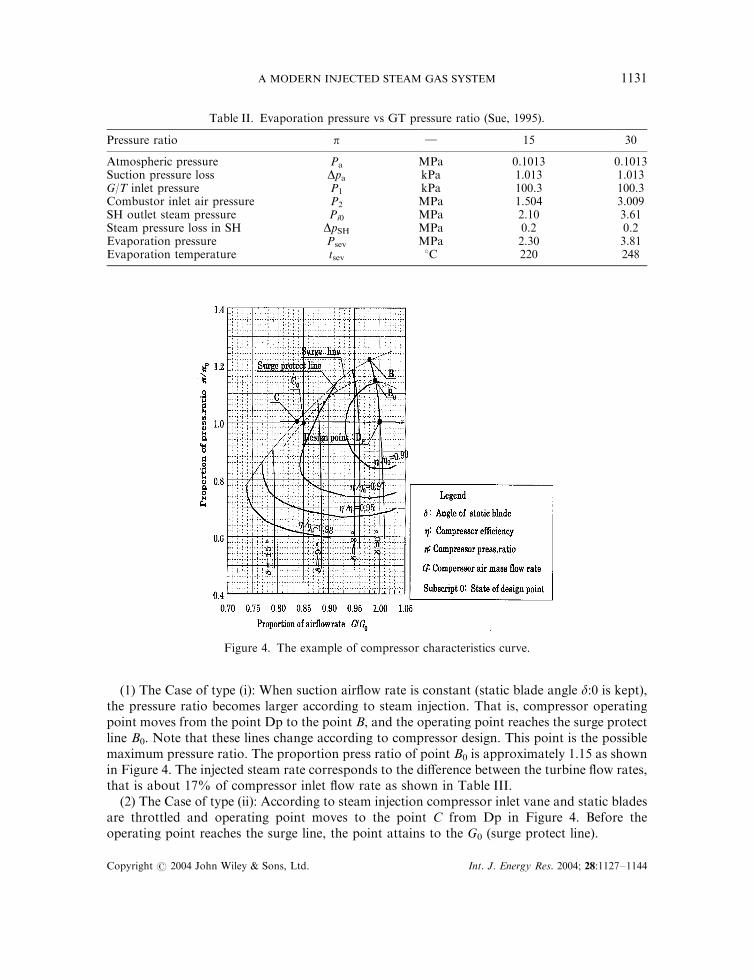
(1) The Case of type (i): When suction airflow rate is constant (static blade angle d:0 is kept),the pressure ratio becomes larger according to steam injection. That is, compressor operatingpoint moves from the point Dp to the point B, and the operating point reaches the surge protectline B0. Note that these lines change according to compressor design. This point is the possiblemaximum pressure ratio. The proportion press ratio of point B0 is approximately 1.15 as shownin Figure 4. The injected steam rate corresponds to the difference between the turbine flow rates,that is about 17% of compressor inlet flow rate as shown in Table III.
(2) The Case of type (ii): According to steam injection compressor inlet vane and static bladesare throttled and operating point moves to the point C from Dp in Figure 4. Before theoperating point reaches the surge line, the point attains to the G0 (surge protect line).
Table II. Evaporation pressure vs GT pressure ratio (Sue, 1995).
Pressure ratio p } 15 30
Atmospheric pressure Pa MPa 0.1013 0.1013Suction pressure loss Dpa kPa 1.013 1.013G/T inlet pressure P1 kPa 100.3 100.3Combustor inlet air pressure P2 MPa 1.504 3.009SH outlet steam pressure Pi0 MPa 2.10 3.61Steam pressure loss in SH DpSH MPa 0.2 0.2Evaporation pressure Psev MPa 2.30 3.81Evaporation temperature tsev 8C 220 248
Figure 4. The example of compressor characteristics curve.
Copyright # 2004 John Wiley & Sons, Ltd. Int. J. Energy Res. 2004; 28:1127–1144
A MODERN INJECTED STEAM GAS SYSTEM 1131
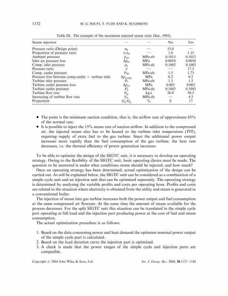
* The point is the minimum suction condition, that is, the airflow rate of approximate 85%of the normal rate.
* It is possible to inject the 15% steam rate of suction airflow. In addition to the compressedair, the injected steam also has to be heated to the turbine inlet temperature (TIT),requiring supply of extra fuel to the gas turbine. Since the additional power outputincreases more rapidly than the fuel consumption of the gas turbine, the heat ratedecreases, i.e. the thermal efficiency of power generation increases.
To be able to optimize the design of the SIGTC unit, it is necessary to develop an operatingstrategy. Owing to the flexibility of the SIGTC unit, basic operating choice must be made. Thequestion to be answered is under what conditions steam should be injected, and how much?
Once an operating strategy has been determined, actual optimization of the design can becarried out. As will be explained below, the SIGTC unit can be considered as a combination of asimple cycle unit and an injection unit that can be optimized separately. The operating strategyis determined by analysing the variable profits and costs per operating hour. Profits and costsare related to the situation where electricity is obtained from the utility and steam is generated ina conventional boiler.
The injection of steam into gas turbine increases both the power output and fuel consumptionat the same compressed air flowrate. At the same time the amount of steam available for theprocess decreases. For the split SIGTC unit this situation can be translated in the simple cyclepart operating at full load and the injection part producing power at the cost of fuel and steamconsumption.
The actual optimization procedure is as follows:
1. Based on the data concerning power and heat demand the optimum nominal power outputof the simple cycle part is calculated.
2. Based on the load duration curve the injection part is optimized.3. A check is made that the power ranges of the simple cycle and injection parts are
compatible.
Table III. The example of the maximum injected steam ratio (Sue, 1995).
Steam injection } } No Yes
Pressure ratio (Design point) p0 } 15.0 }Proportion of pressure ratio p/p0 } 1.0 1.15Ambient pressure pa0 MPa ab. 0.1013 0.1013Inlet air pressure loss Dpin MPa 0.0010 0.0010Comp. inlet pressure pa MPa ab. 0.1003 0.1003Pressure ratio p } } 17.3Comp. outlet pressure P20 MPa ab. 1.5 1.73Pressure loss between comp.outlet � turbine inlet Dpcomp. MPa 0.2 0.2Turbine inlet pressure P3 MPa ab. 1.3 1.5Turbine outlet pressure loss Dpex MPa 0.003 0.003Turbine outlet pressure P4 MPa ab. 0.1043 0.1043Turbine flow rate Gg kg/s 26.0 30.5Increasing of turbine flow rate Ga MPa ab. } 4.5Proportion Ga/Gg % 0 17
Copyright # 2004 John Wiley & Sons, Ltd. Int. J. Energy Res. 2004; 28:1127–1144
M. G. SOUFI, T. FUJII AND K. SUGIMOTO1132
The effect of the recuperator on cycle: The specific heat capacity of the gases will be slightlygreater than that of the air owing to the higher gas temperature and the effect of the products ofcombustion. Likewise the weight of gas flow will be greater than the weight of the air flow by theamount of fuel burned; therefore, the rise in air temperature will be greater than the drop in gastemperature, although the effect of stray heat losses tends to make them approximately equal.The efficiency of the simple Brayton cycle can be greatly improved by the use of regeneration(recuperator), that is the use of exhaust energy to heat the compressed air before it enters thecombustion chamber. The greatest efficiency with regeneration (recuperator) is obtained withthe lowest compression ratio (P2/P1).
NOx reduction in steam-injected gas turbine cycles with recuperator: The production of thermalNOx in the combustion chamber of gas turbines is due to the high flame temperatures existing inthe primary zone where the fuel and air first come together. One effective way to reduce flametemperature is to introduce an inert gas, such as steam, into the combustion process and this hasusually been carried out by the injection of metered steam directly into the primary zone of thecombustor.
In this plant, however, high pressure steam is introduced to the gas fuel, immediatelyupstream of the gas manifold, in order to insure a homogeneous mixture of fuel and steambefore entering the combustor. It has been determined that a premix of steam and fuel controlsan excessive increase in carbon monoxide emissions while reducing the amount of steamrequired to achieve a given NOx level compared to that when directly injecting into thecombustor. Additionally, it is desirable, if possible, to mix the steam and gas such that the steamis slightly wet on entry to the combustion chamber because NOx reduction will be improved dueto the removal of the latent heat of evaporation of wet steam from the hot products ofcombustion; additionally this improvement can be on the maximum level if the temperature inthe combustor is higher than conventional, which it has achieved through the recuperator.
3. THE CALCULATION CONCEPT OF THE CYCLE WITH RECUPERATOR
In general, for the open-loop system, the available energy, that is called as the exergy, isexpressed (Kotas (1995), Johnston (1951)) as
e ¼ h� h0 � T0ðs� s0Þ ð2Þ
where the subscript 0 denotes the external standard environmental state.This value expresses the ability of the maximum work, which working fluid possesses until the
external standard state based on the second law of the thermodynamics. The available energy,which is supplied to any system is utilized but a part is extinguished due to the irreversibleprocess, a loss called ‘Lost Work (LW)’. For example, let us consider the LW for the heattransfer in the heat exchanger as shown in Figure 3. First, the heat quantity exchanged per unittime, Q, is expressed from the heat balance based on the first law of the thermodynamics by(Figure 5)
Q ¼ Ghðhh1 � hh2Þ ¼ Gcðhc2 � hc1Þ ð3Þ
On the other hand, the exergy, DEh and DEc, which the each fluid gets or loses is given by
DEh ¼ Ghðeh1 � eh2Þ; DEc ¼ Gcðec2 � ec1Þ ð4Þ
Copyright # 2004 John Wiley & Sons, Ltd. Int. J. Energy Res. 2004; 28:1127–1144
A MODERN INJECTED STEAM GAS SYSTEM 1133
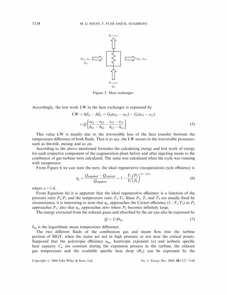
Accordingly, the lost work LW in the heat exchanger is expressed by
LW ¼DEh � DEc ¼ Ghðeh1 � eh2Þ � Gcðec2 � ec1Þ
¼Qeh1 � eh2hh1 � hh2
�ec2 � ec1hc2 � hc1
� �ð5Þ
This value LW is mainly due to the irreversible loss of the heat transfer between thetemperature difference of both fluids. That is to say, the LW occurs in the irreversible processes:such as throttle, mixing and so on.
According to the above mentioned formulas the calculating exergy and lost work of exergyfor each respective component of the cogeneration plant before and after injecting steam to thecombustor of gas turbine were calculated. The same was calculated when the cycle was runningwith recuperator.
From Figure 6 we can state the next, the ideal regenerative (recuperation) cycle efficiency is
Zc ¼Qsupplied � Qrejected
Qsupplied¼ 1�
T1T3
P2P1
� �ðk�1Þ=k
ð6Þ
where k=1.4.From Equation (6) it is apparent that the ideal regenerative efficiency is a function of the
pressure ratio P2/P1 and the temperature ratio T1/T3. Since P1, T1 and T3 are usually fixed bycircumstance, it is interesting to note that Zc, approaches the Carnot efficiency (1�T1/T3) as P2
approaches P1; also that Zc, approaches zero where P2 becomes infinitely large.The energy extracted from the exhaust gases and absorbed by the air can also be expressed by
Q ¼ UAym ð7Þ
ym is the logarithmic mean temperature difference.The two different fluids of the combustion gas and steam flow into the turbine
portion of SIGT, when the states are not in high pressure or not near the critical points.Supposed that the polytropic efficiency Zpt, Isentropic exponent (k) and isobaric specificheat capacity Cp are constant during the expansion process in the turbine, the exhaustgas temperature and the available specific heat drop (Ha) can be expressed by the
hh2 , e h2
h c1, e c1
Gc
h h1 , e h1
Gh
h c2, e c2
Figure 5. Heat exchanger.
Copyright # 2004 John Wiley & Sons, Ltd. Int. J. Energy Res. 2004; 28:1127–1144
M. G. SOUFI, T. FUJII AND K. SUGIMOTO1134
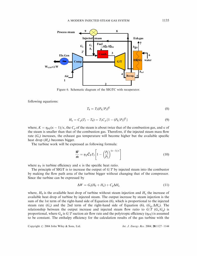
following equations:
T4 ¼ T3ðP4=P3ÞK ð8Þ
Ha ¼ CpðT3 � T4Þ ¼ T3Cpf1� ðP4=P3ÞKg ð9Þ
where, K ¼ ZPTðk� 1Þ=k; the Cp of the steam is about twice that of the combustion gas, and k ofthe steam is smaller than that of the combustion gas. Therefore, if the injected steam mass flowrate (Gs) increases, the exhaust gas temperature will become higher but the available specificheat drop (Ha) becomes bigger.
The turbine work will be expressed as following formula:
’WW
’mm¼ ZT %CCPT3 1�
P4P3
� �ðk�1Þ=k" #
ð10Þ
where ZT is turbine efficiency and k is the specific heat ratio.The principle of SIGT is to increase the output of G/T by injected steam into the combustor
by making the flow path area of the turbine bigger without changing that of the compressor.Since the turbine can be expressed by
DW ¼ GsðH0 þ HaÞ þ CgDHa ð11Þ
where, H0 is the available heat drop of turbine without steam injection and Ha the increase ofavailable heat drop of turbine by injected steam. The output increase by steam injection is thesum of the 1st term of the right-hand side of Equation (6), which is proportional to the injectedsteam rate (Gs) and the 2nd term of the right-hand side of Equation (6), (Gg,DHa). Therelationship between the output increase and injected steam flow ratio to G/T (Gs/Gg) isproportional, where Gg is G/T suction air flow rate and the polytropic efficiency (ZPT) is assumedto be constant. The enthalpy efficiency for the calculation results of the gas turbine with the
89
WGT0+∆ W
Ele.Gen . . water
Comb.
Comp. G/T
Injected steam
HRSG
Recup.
Exh.gas
Fuel
Air
1
3
Gs
4 5
6
7Ga
h ge
∆QF /QF0
Process steam
hs
2’
2
hm5
Figure 6. Schematic diagram of the SIGTC with recuperator.
Copyright # 2004 John Wiley & Sons, Ltd. Int. J. Energy Res. 2004; 28:1127–1144
A MODERN INJECTED STEAM GAS SYSTEM 1135
injected steam is expressed by next formulas:
Zth;GTS ¼ ðWGT0 þ DW Þ=ðQF0 þ DQFÞ
¼ Zth;GT0ð1þ DW =WGT0Þ=ð1þ DQF=QF0Þ ð12Þ
In case of the cycle with recuperator where the DQF is approx. (zero) so, Equation (7) will beexpressed as following:
Zth;GTS ¼WGT0 þ DW
QF0¼
EF0
QF0Zex ¼
EF0
QF0¼ 1�
PðLWÞGTS
EF0
� �ð13Þ
where Zth,GTS is also called the power generation efficiency. The exergy efficiency in G/T systemfor the calculation results of the plant are expressed by
Zex;GTS ¼WGT0 þ DW
EF0¼
EF0 �P
ðLWÞGTS
EF0¼ 1�
PðLWÞGTS
EF0ð14Þ
Zth,GTS, becomes higher according to Gs/Gg. The differences of Zth,GTS due to G/T inlettemperature TIT in the case of G/T pressure ratio p of (30) are not as large as those of p (15).The total enthalpy efficiency in cogeneration system with (Cheng cycle) for the calculationresults of the plant with recuperator is expressed by next formulas:
Zth;cog ¼ðWGT0 þ DW Þ þ Qcog
QF0ð15Þ
The total exergy efficiency in cogeneration system is
Zex;cog ¼ðWGT0 þ DW Þ þ Ecog
EF0
¼EF0 �
PðLWÞcog
EF0¼ 1�
PðLWÞcogEF0
ð16Þ
From the heat balance of the exaust gas and the steam after superheater, the produced steamflow rate (Gs) can be calculated by the following equation:
Gs ¼ fGgðhm5 � hgeÞ=ðhS2 � hSFÞ ð17Þ
where f is the heat loss coefficient of HRSG.Generally, the bigger is the p of a G/T, the lower the exhaust gas temperature will become,
and it is necessary to raise the injected steam pressure. It means, the higher is the p of a G/T, theless will be the heat capacity given by the exhaust gas (hm5hge) and the produced steam flow rate(Gs) will become smaller as the p of G/T becomes higher.
4. BASIC CONDITIONS AND ASSUMPTIONS
The fundamentals of calculating condition and assumption are shown below:For the cogeneration power plant with 30MW gas turbine (Mitsubishi Kawasaki’s gas
turbine). {G/T output (net):30MW, gross heat rate (LHV):50.427 kJ kg�1}. This plant is to beused as the standard referring to the comparing results and assumptions after modification ofthe plants with injected steam and recuperator.
Copyright # 2004 John Wiley & Sons, Ltd. Int. J. Energy Res. 2004; 28:1127–1144
M. G. SOUFI, T. FUJII AND K. SUGIMOTO1136
Efficiency of the G/T: 90%; the polytropic efficiency Zpt is assumed to be constant; Efficiencyof CEP:75%; Efficiency of the compressor: 88%; Combustor pressure ratio=18.24 (1824 kPa);Efficiency of the HRSG: 90%; Efficiency of the generator: 95%; Efficiency of the BFP(HP,LP):75%; TIT=12508C; Fuel energy mass flow rate : 1.86 kg s�1. Radiation heat is neglected. Airdifference temperature in recuperator DT=788C. The above performance is at a specifiedambient temperature of 158C, 60%RH, 101.3 kPa (atmosphere pressure) and natural fuel gas.
5. RESULTS AND DISCUSSIONS
According to the theory and calculation condition sections mentioned above, the results showthat the optimizing cycle which maximizes the power generation efficiency, Zth,GTS, (Equation(13) and Figure 14) is obtained at the injected steam of 30% of the steam quantity. Itcorresponds to injected steam rate of about 15% of suction air mass flow rate as the maximumsteam which can be injected to the gas turbine and without increasing the fuel mass flow ratebecause of the effect of recuperator.
The normal operation of the plant means the normal operation condition of the sameprospective components of the cycle of kawasaki’s gas turbine with the same main parameters ofpressure ratio (p=18.24) and temperature (T=12508C), and the cycle is running withoutinjected steam and recuperator. (The fundamental results in this case are expressed in theTable IV. These results were obtained by the calculation of the same formulas obtained intheory and calculation condition sections in this paper).
Accordingly, when the flow rate of Gs/Ga is 0% it means the cycle is running on normaloperation condition without both of the injected steam and recuperator. When the injectedsteam flow rate Gs/Ga starts to increase until the value of 30%, which is the optimum range ofinjected steam and with the same main parameters of normal operating condition of pressureratio (p=18.24) and temperature (T=12508C), this condition is also called normal operationand the all obtained results and discussion will be based on this case.
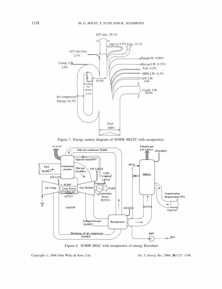
Figure 7 shows the exergy sankey diagram of 30 MW SIGTC power plant which can expressalso the advantage of the cycle with recuperator. The value of the exergy loss LW is the greatestin the combustor which is about 29.6% per input exergy of the fuel. Note that this value on thenormal operation without both injected steam and recuperator is 28.44% as shown in Table IVand this increase is due to the injected steam to the combustor and regeneration of compressedair. The calculation results of the exergy balance are shown in Figure 8. The exergy flowsheetdiagram of this power plant was compared with the normal operation condition without
Table IV. The normal operating condition of 30MW cogeneration power plantwithout injected steam and recuperator.
Zth,cog(%)
HRB,
LW (%)
Fuel
exergy,
(kW)
Exh, gas
enthalpy
(%)
Air
comp.
flow
rate,
(kg s�1)
Exh. gas
exergy
(%)
G/T
Output
power,
(kW)
TIT
(8C)
G/T
LW
(%)
Zth,gt(%)
Zex,gt(%)
Comb.
LW
(%)
G/T exh.
temp.
(8C)
45.10 7.19 93 627 24.43 104.30 6.23 29 480 1250 3.25 28.95 33.78 28.44 540
Copyright # 2004 John Wiley & Sons, Ltd. Int. J. Energy Res. 2004; 28:1127–1144
A MODERN INJECTED STEAM GAS SYSTEM 1137
Exh. 6.2%
PumpLW. 0.09%
HRB LW. 6.3%
Recop.LW. 0.23%
Air compressor Energy 43.3%
injec.st 5.5% Cog. 13.1%
Fuel100%
CoolingAir
energy
6.5%
93.4%
Comp. LW2.4%
G/T LW. 3.4%
Comb. LW29.6%
G/T elec. 39.1%
G/T elec.loss2.1%.
Figure 7. Exergy sankey diagram of 30MW SIGTC with recuperator.
injected steam30%
LW6,020.5
LW 2,272
LW223.5
1,872.8
LW 3,262.8
LW 28 28 ,545 545
24,131.8
41,810
5,305
497.8
Inlet air combustor 39,848
66.4 Discharge of air compressor
29,640.8
Exhaust hot gas 34,562.7
Generation Power
39,727.3
Generator
Air 0
Cooling air
6,271.5
Fuel
96,481.5
Com. Power Air Comp.
Hot gas 113,090.5
Unit kW
Combustion chamber
HeHe atat
Recocovery ry
BoBoilerer
Gas Turbine
Exhaust gas LW 5,991.5
Recuperator
HRSG
Cogeneration Requirement 70%
12,617.6
BFP
37,855
Figure 8. 30MW SIGC with recuperator of energy flowsheet.
Copyright # 2004 John Wiley & Sons, Ltd. Int. J. Energy Res. 2004; 28:1127–1144
M. G. SOUFI, T. FUJII AND K. SUGIMOTO1138
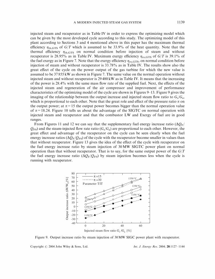
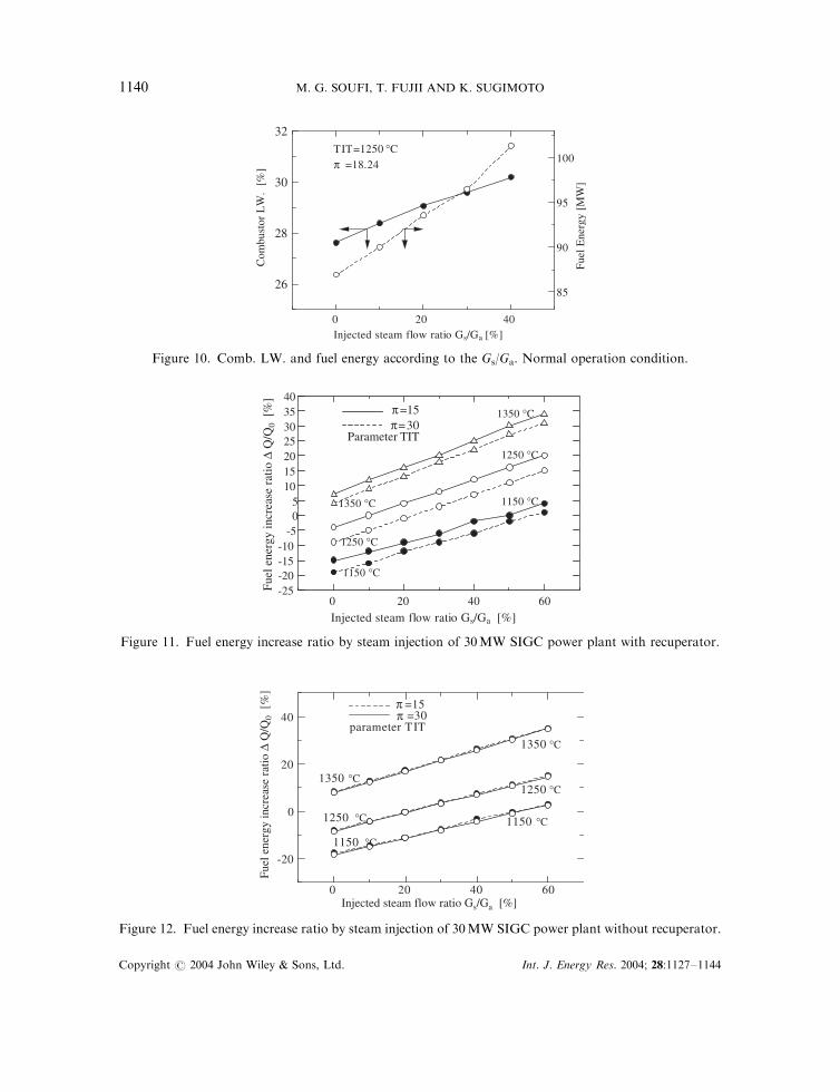
injected steam and recuperator as in Table IV in order to express the optimizing model whichcan be given by the most developed cycle according to this study. The optimizing model of thisplant according to Sections 3 and 4 mentioned above in this paper has the maximum thermalefficiency Zth,GTS of G/T which is assumed to be 33.9% of the heat quantity. Note that thethermal efficiency Zth,GTS on normal condition before injection of steam and withoutrecuperator is 28.95% as in Table IV. Maximum exergy efficiency Zex,GTS of G/T is 39.1% ofthe fuel exergy as in Figure 7. Note that the exergy efficiency Zex,GTS, on normal condition beforeinjection of steam and without recuperator is 33.78% as in Table IV. The results show also thegreat effect of the cycle on the power output of the gas turbine for which the new value isassumed to be 37 855 kW as shown in Figure 7. The same value on the normal operation withoutinjected steam and without recuperator is 29 480 kW as in Table IV. It means that the increasingof the power is 28.4% with the same mass flow rate of the supplied fuel. Next, the effects of theinjected steam and regeneration of the air compressor and improvement of performancecharacteristics of the optimizing model of the cycle are shown in Figures 9–13. Figure 9 gives theimaging of the relationship between the output increase and injected steam flow ratio to Gs/Ga,which is proportional to each other. Note that the great role and effect of the pressure ratio p onthe output power; at p=15 the output power becomes bigger than the normal operation valueof p=18.24. Figure 10 tells us about the advantage of the SIGTC on normal operation withinjected steam and recuperator and that the combustor LW and Exergy of fuel are in goodranges.
From Figures 11 and 12 we can say that the supplementary fuel energy increase ratio (DQF/QF0) and the steam-injected flow rate ratio (Gs/Ga) are proportional to each other. However, thegreat effect and advantage of the recuperator on the cycle can be seen clearly when the fuelenergy increase ratios (DQF/QF0) of the cycle with the recuperator become smaller in values thanthat without recuperator. Figure 13 gives the idea of the effect of the cycle with recuperator onthe fuel energy increase ratio by steam injection of 30MW SIGTC power plant on normaloperation than that without recuperator. That is to say, for the same output power of the G/Tthe fuel energy increase ratio (DQF/QF0) by steam injection becomes less when the cycle isrunning with recuperator.
0 20 40 60-40-30-20-10
01020
304050607080
π =15π =30
Parameter TIT
1350
1350
1250
1250
1150 °C
°C
°C
°C
°C
°C
1150
Injected steam flow ratio Gs /Ga [%]
Out
put i
ncre
ase
ratio
∆W
/W0
[%]
Figure 9. Output increase ratio by steam injection of 30MW SIGC power plant with recuperator.
Copyright # 2004 John Wiley & Sons, Ltd. Int. J. Energy Res. 2004; 28:1127–1144
A MODERN INJECTED STEAM GAS SYSTEM 1139
0 20 40
26
28
30
32
85
90
95
100TIT=1250 °C π =18.24
Injected steam flow ratio Gs/Ga [%]
Com
bust
or L
W.
[%]
Fuel
Ene
rgy
[MW
]
Figure 10. Comb. LW. and fuel energy according to the Gs/Ga. Normal operation condition.
0 20 40 60-25-20-15-10
-505
10152025303540
Injected steam flow ratio Gs/Ga [%]
Fuel
ene
rgy
incr
ease
rat
io ∆
Q/Q
0 [
%]
π=15π=30
Parameter TIT
1350 °C
1350 °C
1250 °C
1250 °C
1150 °C
1150 °C
Figure 11. Fuel energy increase ratio by steam injection of 30MW SIGC power plant with recuperator.
0 20 40 60
-20
0
20
40
1150 °C
1150 °C
1250 °C
1250 °C
1350 °C
1350 °C
parameter TIT
=15π π
=30
Injected steam flow ratio Gs/Ga [%]
Fuel
ene
rgy
incr
ease
rat
io ∆
Q/Q
0 [
%]
Figure 12. Fuel energy increase ratio by steam injection of 30MW SIGC power plant without recuperator.
Copyright # 2004 John Wiley & Sons, Ltd. Int. J. Energy Res. 2004; 28:1127–1144
M. G. SOUFI, T. FUJII AND K. SUGIMOTO1140
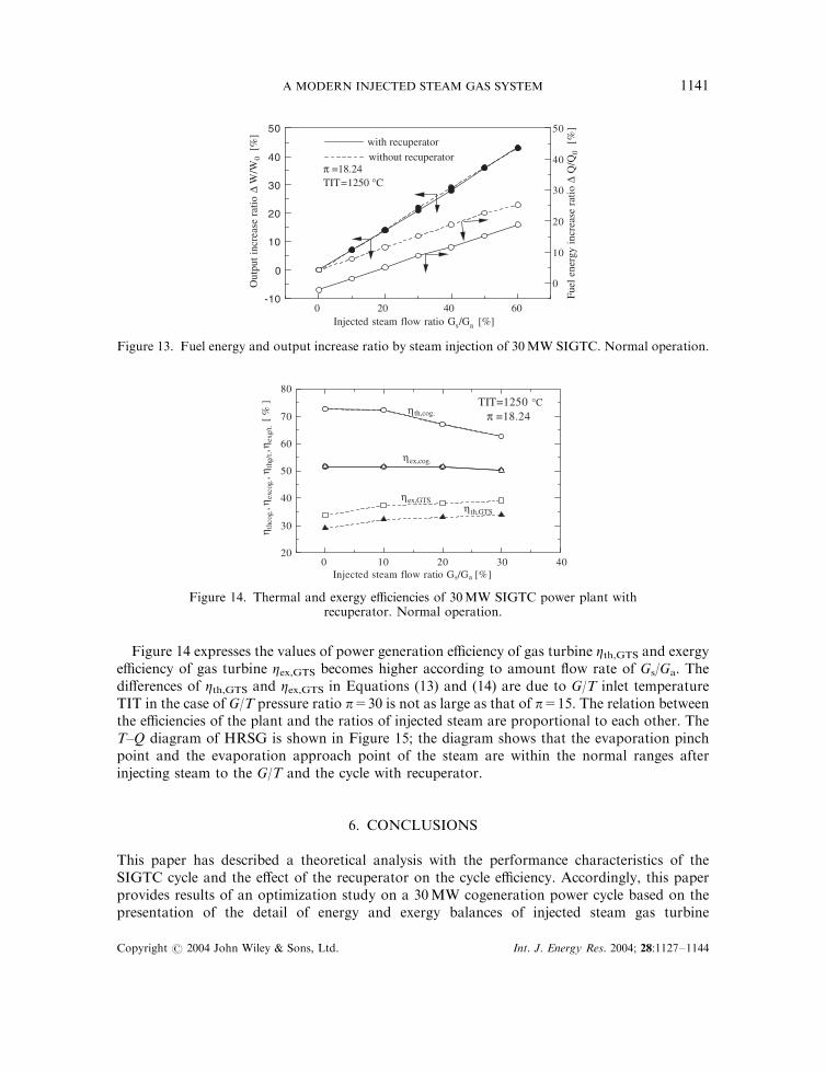
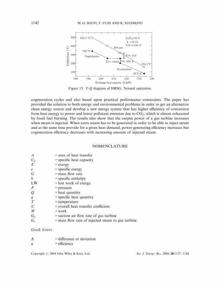
Figure 14 expresses the values of power generation efficiency of gas turbine Zth,GTS and exergyefficiency of gas turbine Zex,GTS becomes higher according to amount flow rate of Gs/Ga. Thedifferences of Zth,GTS and Zex,GTS in Equations (13) and (14) are due to G/T inlet temperatureTIT in the case of G/T pressure ratio p=30 is not as large as that of p=15. The relation betweenthe efficiencies of the plant and the ratios of injected steam are proportional to each other. TheT–Q diagram of HRSG is shown in Figure 15; the diagram shows that the evaporation pinchpoint and the evaporation approach point of the steam are within the normal ranges afterinjecting steam to the G/T and the cycle with recuperator.
6. CONCLUSIONS
This paper has described a theoretical analysis with the performance characteristics of theSIGTC cycle and the effect of the recuperator on the cycle efficiency. Accordingly, this paperprovides results of an optimization study on a 30MW cogeneration power cycle based on thepresentation of the detail of energy and exergy balances of injected steam gas turbine
0 20 40 60-10
0
10
20
30
40
50
0
10
20
30
40
50with recuperatorwithout recuperator
π =18.24TIT=1250 °C
Injected steam flow ratio Gs/Ga [%]
Fuel
ene
rgy
incr
ease
rat
io ∆
Q/Q
0 [
%]
Out
put i
ncre
ase
ratio
∆W
/W0
[%
]
Figure 13. Fuel energy and output increase ratio by steam injection of 30MW SIGTC. Normal operation.
0 10 20 30 4020
30
40
50
60
70
80
ηth
cog.
, ηex
cog.
, ηth
g/t. ,
η exg
/t. [
% ]
Injected steam flow ratio Gs/Ga [%]
ηth,cog.
ηth,GTS
ηex,GTS
ηex,cog.
TIT=1250 °C
π =18.24
Figure 14. Thermal and exergy efficiencies of 30MW SIGTC power plant withrecuperator. Normal operation.
Copyright # 2004 John Wiley & Sons, Ltd. Int. J. Energy Res. 2004; 28:1127–1144
A MODERN INJECTED STEAM GAS SYSTEM 1141
cogeneration cycles and also based upon practical performance constraints. The paper hasprovided the solution to both energy and environmental problems in order to get an alternativeclean energy source and develop a new energy system that has higher efficiency of conversionfrom heat energy to power and lower pollutant emission due to CO2, which is almost exhaustedby fossil fuel burning. The results also show that the output power of a gas turbine increaseswhen steam is injected. When extra steam has to be generated in order to be able to inject steamand at the same time provide for a given heat demand, power generating efficiency increases butcogeneration efficiency decreases with increasing amount of injected steam.
NOMENCLATURE
A =area of heat transferCp =specific heat capacityE =exergye =specific exergyG =mass flow rateh =specific enthalpyLW =lost work of exergyP =pressureQ =heat quantityq =specific heat quantityT =temperatureU =overall heat transfer coefficientW =workGa =suction air flow rate of gas turbineGs =mass flow rate of injected steam to gas turbine
Greek letters
D =difference or deviationZ =efficiency
180 190 200 210 220 230 240
100
200
300
400
500
340 °C
Superheater
Eva. steam Eva. app. p.
Economizer
494.3 °C
156.2 °C
80.5 °C
Hot gas
Exchange heat capacity Q [kW]
Tem
pera
ture
[°C
]
Gs/Ga=30 %
π =18.24TIT=1250 °C
Eva. p.p.
Figure 15. T–Q diagram of HRSG. Normal operation.
Copyright # 2004 John Wiley & Sons, Ltd. Int. J. Energy Res. 2004; 28:1127–1144
M. G. SOUFI, T. FUJII AND K. SUGIMOTO1142
ym = logarithmic mean temperature differencek = isentropic exponent
Subscripts
g =gasGT =gas turbineex =exergyExh. =exhaustF =fuelh =heatm =mixture of combustion gas and steamp =pointST =steam turbineTh =thermal0 =state without steam injection (conventional state)
Abbreviations
BFP =boiler feed pumpCC =combustion chamberComp =compressorCEP =condensate extraction pumpEC =economizerEV =evaporatorHRSG =heat recovery steam generatorSIGTC =steam-injected gas turbine cycle (Cheng cycle)SH =superheaterTIT =turbine inlet temperature
REFERENCES
Baken AM. 1988. Optimized operation of steam-injected gas turbine cogeneration units. ASME COGEN-TURBO, 2ndInternational Symposium on Turbo machinery, Combined-cycle Technologies and Cogeneration, vol. ASME-IGTI-3.Montreux, Switzerland, 30 August–1 September, 259–265.
Cain WG. 1988. Gas turbine cogeneration system with steam injection. PB89-162143.Cain WG. 1989. Gas turbine cogeneration system with steam injection. PB90-198482.De Paepe M, Dick E. 2000. Cycle Improvements to steam injected gas turbines. International Journal of Energy Research
24:1081–1107 (Copyright # 2000 John Wiley & Sons, Ltd.).Hyprotech, Property Methods and Calculations. 2000. HYSYS Version 2.2 Reference, 207.Johnston RM, Brockett WA, Bock AE. 1951. Elements of Applied Thermodynamics. United States Naval Institute:
Annapolis, MA.Kaempffer L, et al. 1989. Steam injecting a mature gas turbine in a modern cogeneration plant. ASME Paper 89-GT-167.Kotas TJ. 1995. The Exergy Method of Thermal Plant Analysis. Krieger Publishing Company: Malabar, FL.Larson ED, et al. 1986. Steam injected gas turbines. ASME Paper 86-GT-47.Little DA. 1988. Steam injection of frame 5 gas turbine for power augmentation in cogeneration service. ASME Paper
88-GT-51.Soufi MG, Fujii T, Sugimoto K. 2002. Improvement of performance characteristics of power generation cycle with gas
turbine. Memoirs of Graduate School of Science and Technology Kobe University, No. 20-A, March.
Copyright # 2004 John Wiley & Sons, Ltd. Int. J. Energy Res. 2004; 28:1127–1144
A MODERN INJECTED STEAM GAS SYSTEM 1143

Soufi MG, Fujii T, Sugimoto K. 2003. A clean environment gas turbine cogeneration plant. The 6th ASME–JSMEThermal Engineering Joint Conference, Hawaii, USA. 16–20 March (TED}AJ03-169).
Soufi MG, Fujii T, Sugimoto K. 2002. Gas turbine cogeneration system with steam injection. A modern cogenerationplant. The 13th International Symposium on Transport Phenomena, under the auspice of (PCTFE), USA. Vic., Canada.
Sue, M. 1995. Application of steam injected gas turbine to waste to energy systems (95- Yokohama-IGTC-100,III}309).
Westsik JH. 1987. Steam injected gas turbines for moderate size power generation. Proceedings of the 14th EnergyTechnology Conference, Washington, DC, 14–16 April:1185–1197.
Wilhelmsson A. 1988. Clean uprating by steam injection. Modern Power System 8(5):33–34.
Copyright # 2004 John Wiley & Sons, Ltd. Int. J. Energy Res. 2004; 28:1127–1144
M. G. SOUFI, T. FUJII AND K. SUGIMOTO1144