Embed Size (px)
Citation preview
A model for shear behavior of anchors in external shear walled frames
İffet Feyza Çırak*1, Hasan Kaplan2, Salih Yılmaz3, Özlem Çalışkan
Değirmenci4, Nihat Çetinkaya2
Online Publication Date: 4 May 2015
URL: http://www.jresm.org/archive/resm2015.05st0211.html
DOI: http://dx.doi.org/10.17515/resm2015.05st0211
Journal Abbreviation: Res. Eng. Struct. Mat.
To cite this article
Çırak İF, Kaplan H, Yılmaz S, Değirmenci ÖÇ, Çetinkaya N. A model for shear behavior of
anchors in external shear walled frames. Res. Eng. Struct. Mat., 2015; 1: 53– 71.
Disclaimer
All the opinions and statements expressed in the papers are on the responsibility of author(s) and are
not to be regarded as those of the journal of Research on Engineering Structures and Materials (RESM)
organization or related parties. The publishers make no warranty, explicit or implied, or make any
representation with respect to the contents of any article will be complete or accurate or up to date. The
accuracy of any instructions, equations, or other information should be independently verified. The
publisher and related parties shall not be liable for any loss, actions, claims, proceedings, demand or
costs or damages whatsoever or howsoever caused arising directly or indirectly in connection with use
of the information given in the journal or related means.

*Corresponding author: [email protected] DOI: http://dx.doi.org/10.17515/resm2015.05st0211
Res. Eng. Struct. Mat. Vol.1 Iss.2 (2015) 53 – 71 53
Research Article
A model for shear behavior of anchors in external shear walled frames
İffet Feyza Çırak*1, Hasan Kaplan2, Salih Yılmaz3, Özlem Çalışkan Değirmenci4, Nihat Çetinkaya2
1Suleyman Demirel University, Department of Civil Engineering, Turkey 2 Pamukkale University, Department of Civil Engineering, Turkey 3 Kâtip Çelebi University, Department of Civil Engineering, Turkey 4Bilecik Şeyh Edebali University, Department of Civil Engineering, Turkey
Article Info Abstract
Article history: Received 11 Feb 2015 Revised 14 Apr 2015 Accepted 15 Apr 2015
Retrofit of the existing seismically deficient buildings is a common need especially in earthquake prone regions. Chemical anchors are widely used to connect existing and newly added structural elements, such as shear walls. Therefore, modelling the behaviour of anchors which transfer axial and shear forces to the added members is important for design and analyses. There is no anchor model present in the current literature accounting shear behaviour. Therefore, a new model is established using results of a comprehensive experimental study conducted at Pamukkale University Earthquake and Construction Technology Research Laboratory. In this study, mentioned shear model is tested using two- story, one-bay RC frame specimens strengthened with external shear walls. In analyses of the models, SAP 2000 software is used and nonlinear shear behaviour of anchors is represented by NLLink elements. It is concluded that, suggested anchor shear model may be used for modelling external shear wall anchor behaviour.
© 2015 MIM Research Group. All rights reserved.
Keywords: External shear wall Chemical anchor Shear strength Anchor shear model Nonlinear analyses
1. Introduction
Most of the existing reinforced concrete residential buildings in many countries are seismically deficient because the load carrying system of these buildings contains deficiencies like soft stories, nonseismic reinforcement detailing and strong beam-weak column connections [1]. Safety and prevention of total collapse of a structure are the prime requirements of buildings. In order to meet these requirements, the structure should have adequate lateral strength, lateral stiffness and sufficient ductility [2]. Heavy damage and total collapse of RC buildings after the major earthquakes in the last three decades has initiated studies on strengthening techniques [3]. In strengthening reinforced concrete structures, two rehabilitation approaches are generally considered. One is global modification, the other is local modification. In local modification, deformation capacities of components are increased to the determined limit values, so damage occurrence is delayed. But, in this approach, there is no meaningful change in lateral load capacity. Adding concrete, steel, FRP (Fiber Reinforced Polymer) and reinforced concrete jackets for columns are possible methods for this approach [4]. In global modification, a general
Header: ( Font Cambria, 8pt font size, Italic, Centered)

Çırak et al. / Research on Engineering Structures & Materials 2 (2015) 53-71
54
modification is aimed. Reinforced concrete or steel shear walls are added. In Fig. 1, the effect of these two strengthening approaches on lateral load and deformation capacity are illustrated.
(a) (b)
Fig. 1 Comparison of component (a) and system (b) strengthening [4]
In local modification, ductilities of components are usually increased for contributing ductility of the structural system. In global modification, load capacity of the structural system is increased by increasing the strength and stiffness of the structural system. In this way, structural system can fulfil the seismic forces with enough safety.
In global modification, adding shear walls is usually preferred. If addition of the shear wall is inside the structure, reinforced concrete shear wall is placed by removing existing infill wall. If the addition is outside of the building, shear wall can be added without removing existing infills. By rehabilitation of existing infills, the lateral load capacity of structure can be increased, as well. Research on this subject is in progress [1].
Recently, it is observed that lateral stiffness and strength of damaged and non-damaged reinforced concrete frames can be increased considerably by strengthening infill walls [5]. Besides, it was stated that infill walls can be used to control inter-story drift and out-of-plane failure [6].
It is concluded that, external shear wall application can provide system rehabilitation effectively and economically. Thus, in recent years this method is used commonly. Chemical anchors are widely used in external shear wall applications [7]. However, it is known that shear behaviour of anchors have an impact on capacity. Though, it is noticed that there is not any model concerning shear behaviour of anchors. In the referenced study [8], a model is suggested for shear behaviour of anchors by using multiple regression analysis. In this study, this shear model is used with the aim of modelling behaviour of external shear walls and compared with experimental results.
2. Material and Method
Chemical anchors are widely used to connect structural elements. They are embedded in the holes placed in hardened concrete. The diameter of the anchor hole which is drilled is at most 50% larger than that of the bar diameter. Chemical anchors have begun to be frequently used with the development of high resistance adhesives.
In the existing literature, it is observed that there are limited studies about shear behaviour of anchors. Besides that, there is not any model suggested for shear behaviour. In this study, two-story, one-bay RC frame specimens strengthened with external shear walls are modelled in SAP 2000 [9] and nonlinear static pushover analyses are performed. In analyses, anchor shear model established by using multiple regression method is used to

Çırak et al. / Research on Engineering Structures & Materials 2 (2015) 53-71
55
simulate shear behaviour of anchors [8]. Nonlinear static pushover analyses can be described as pushing until the stability of the structural system is lost. The applied lateral forces should represent behaviour of structure under lateral earthquake forces. The representative lateral load pattern is simultaneous lateral loading in experiments as pushing from floor levels. Scale of force between 1st and 2nd floor is considered as 1:2 (Fig. 2).
Fig. 2 Load pattern used in analyses
After determining load pattern, by controlling displacement of the roof or a certain node, lateral forces are applied monotonically step-by-step. In every step, relationship between the base shear force and the displacement of the roof is recorded. Also, it is controlled that, if predetermined hinge zones are reached their capacity. In plastic hinge zones, structural component is divided into two and hinge zone is transformed to a node. A rotation redor is defined for this node that represents rotation stiffness and analysis goes on. Analysis continues until the structure loses its stability. Thus, capacity curve (lateral load-roof displacement) is obtained (Fig. 3). In this study, multi pointed idealization is conducted with NLLink elements (nonlinear connection) rather than classic plastic hinges.
Fig. 3 Load pattern and base shear-roof displacement [10]
Suggested anchor shear model (Eqn.1) represents the shear behaviour of anchors that connect external shear wall and existing frames (Fig. 4).
Vt
Vt
Vt
Vt

Çırak et al. / Research on Engineering Structures & Materials 2 (2015) 53-71
56
Fig. 4 Frame strengthened with external shear wall
0.50.5y
fa L55.3)FL(D2D)(L44.10V c (1)
Here, Va: Anchor shear load (kN); fc: Concrete compressive strength (kN/mm2); fy: Steel yielding strength (kN/mm2); D: Steel diameter (mm); L: Embedment depth (mm).
In this equation, anchor shear value is dependent on anchor diameter (D), embedment depth (L), compressive strength of concrete (fc) and steel yield strength (fy). In Fig. 5, parameters of suggested anchor shear model formula are given.
Fig. 5 Some parameters of suggested anchor shear model formula.
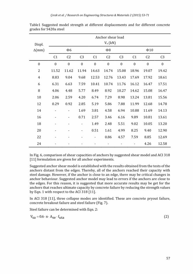
Nonlinear load-displacement features are calculated by using suggested model for anchors having different diameter (D) and embedment depth (L) as given in Table 1. For all anchors, embedment depth (L) is 10. Namely, for 6, embedment depth is 60 mm, for 8, 80 mm, for 10, 100 mm. Experimentally determined mean yield strength value is used as yield point of steel. Here, C1, C2, C3 represent the concrete compressive strength of specimens, 5.7 MPa, NLLink element representing the anchor.
Çırak et al. / Research on Engineering Structures & Materials 2 (2015) 53-71
57
Table1 Suggested model strength at different displacements and for different concrete grades for S420a steel
Displ.
(mm)
Anchor shear load
Va (kN)
6 8 10
C1 C2 C3 C1 C2 C3 C1 C2 C3
0 0 0 0 0 0 0 0 0 0
2 11.52 11.62 11.94 14.63 14.74 15.08 18.96 19.07 19.42
4 8.83 9.04 9.68 12.53 12.76 13.43 17.69 17.92 18.61
6 6.31 6.63 7.59 10.41 10.74 11.76 16.12 16.47 17.51
8 4.06 4.48 5.77 8.49 8.92 10.27 14.62 15.08 16.47
10 2.06 2.59 4.20 6.74 7.29 8.98 13.24 13.81 15.56
12 0.29 0.92 2.85 5.19 5.86 7.88 11.99 12.68 14.78
14 - - 1.69 3.81 4.58 6.94 10.88 11.69 14.13
16 - - 0.71 2.57 3.46 6.16 9.89 10.81 13.61
18 - - - 1.49 2.48 5.51 9.02 10.05 13.20
20 - - - 0.51 1.61 4.99 8.25 9.40 12.90
22 - - - - 0.86 4.57 7.59 8.85 12.69
24 - - - - - - - 4.26 12.58
In Fig. 6, comparison of shear capacities of anchors by suggested shear model and ACI 318 [11] formulation are given for all anchor experiments.
Suggested anchor shear model is established with the results obtained from the tests of the anchors distant from the edges. Thereby, all of the anchors reached their capacity with steel damage. However, if the anchor is close to an edge, there may be critical changes in anchor behaviour. Suggested anchor model may lead to errors if the anchors are close to the edges. For this reason, it is suggested that more accurate results may be get for the anchors that reaches ultimate capacity by concrete failure by reducing the strength values by Eqn. 1 with respect to the ACI 318 [11].
In ACI 318 [11], three collapse modes are identified. These are concrete pryout failure, concrete breakout failure and steel failure (Fig. 7).
Steel failure can be determined with Eqn. 2:
utafseAn6.0saV (2)

Çırak et al. / Research on Engineering Structures & Materials 2 (2015) 53-71
58
Fig. 6 Comparison of shear capacities of anchors by suggested shear model and ACI 318 [11] formulation
Fig. 7 Anchor failure modes under shear loading in ACI 318 [11]
Here, n is number of anchors in group, Ase is cross sectional area of an anchor (mm2), utaf
is, tensile strength of the anchor steel (N/mm2).
In concrete edge failure, breakout capacity for single anchor ( bV ) can be computed by Eqn.
3.
5.11a
'c0
2.0
0
eb )c(fd)
d
l(6.0V (3)
Here, el (mm) is effective anchor depth, 0d (mm) is bar diameter , 1ac (mm) is distance to
free edge taken in the direction of the applied shear and '
cf (MPa) is specified concrete
strength. For the pryout collapse of concrete, ACI 318 [11] presents Eqn. 4 and Eqn. 5 for single and group anchors respectively.
cbcpcp NkV (for single anchors) (4)
cbgcpcpg NkV (for group anchors) (5)
a) concrete pryout failure b) concrete breakout failure c) steel failure
Çırak et al. / Research on Engineering Structures & Materials 2 (2015) 53-71
59
Here, cpV (N) and cpgV (N) are nominal concrete pryout strength of single and group
anchors; cbN (N) and cbgN (N) are nominal concrete breakout strength in tension of single
and group anchors, respectively. cpk is a constant that changes with embedment depth of
anchors. For shallow anchors (hef <65 mm), cpk is 1.0. For other effective depth values (hef
≥65), cpk is 2.0.
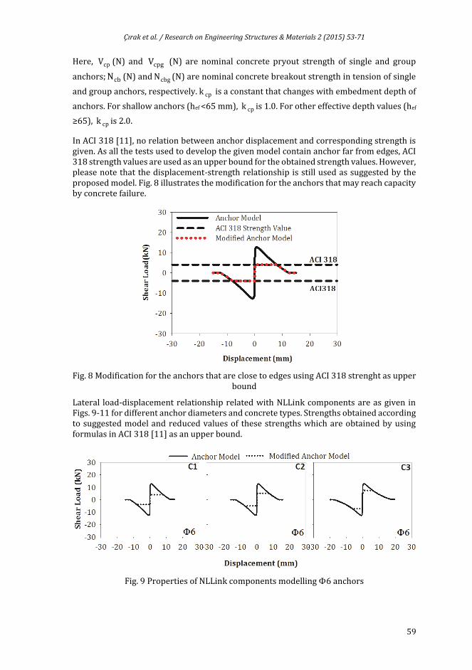
In ACI 318 [11], no relation between anchor displacement and corresponding strength is given. As all the tests used to develop the given model contain anchor far from edges, ACI 318 strength values are used as an upper bound for the obtained strength values. However, please note that the displacement-strength relationship is still used as suggested by the proposed model. Fig. 8 illustrates the modification for the anchors that may reach capacity by concrete failure.
Fig. 8 Modification for the anchors that are close to edges using ACI 318 strenght as upper bound
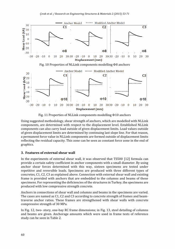
Lateral load-displacement relationship related with NLLink components are as given in Figs. 9-11 for different anchor diameters and concrete types. Strengths obtained according to suggested model and reduced values of these strengths which are obtained by using formulas in ACI 318 [11] as an upper bound.
Fig. 9 Properties of NLLink components modelling6 anchors
Çırak et al. / Research on Engineering Structures & Materials 2 (2015) 53-71
60
Fig. 10 Properties of NLLink components modelling 8 anchors
Fig. 11 Properties of NLLink components modelling10 anchors
Using suggested methodology, shear strength of anchors, which are modelled with NLLink components, are determined with respect to the displacement level. Established NLLink components can also carry load outside of given displacement limits. Load values outside of given displacement limits are determined by continuing last slope line. For that reason, a permanent force value in NLLink components are formed outside of displacement limits reflecting the residual capacity. This zone can be seen as constant force zone in the end of graphics.
3. Features of external shear wall
In the experiments of external shear wall, it was observed that TS500 [12] formula can provide a certain safety coefficient in anchor components with a small diameter. By using anchor shear forces determined with this way, sixteen specimens are tested under repetitive and reversible loads. Specimens are produced with three different types of concretes, C1, C2, C3 as explained above. Connection with external shear wall and existing frame is provided with anchors that are embedded to the columns and beams of these specimens. For representing the deficiencies of the structures in Turkey, the specimens are produced with low compressive strength concrete.
Anchors in connections of shear wall and columns and beams in the specimens are varied. The cases are named as C1, C2 and C3 according to concrete strength of frames and beam-traverse anchor ratios. These frames are strengthened with shear walls with concrete compressive strength of 30 MPa.
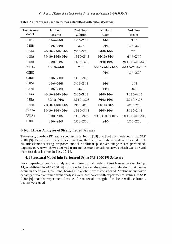
In Fig. 12, two- story, one-bay RC frame dimensions; in Fig. 13, steel detailing of columns and beams are given. Anchorage amounts which were used in frame tests of reference study can be seen in Table 2.

Çırak et al. / Research on Engineering Structures & Materials 2 (2015) 53-71
61
Fig. 12 Dimensions of two- story, one-bay RC frame specimens
Fig. 13 Detailing of columns and beams
Çırak et al. / Research on Engineering Structures & Materials 2 (2015) 53-71
62
Table 2 Anchorages used in frames retrofitted with outer shear wall
Test Frame Models
1st Floor
Column
2nd Floor
Column
1st Floor
Beam
2nd Floor
Beam
C1DE 36+28 16+28 18 36
C2ED 16+28 36 26 16+28
C2AA 410+28+36 26+58 38+16 78
C2BA 310+18+26 110+38 110+36 68+26
C2BB 58+36 48+16 28+16 210+18+26
C2DA+ 110+28 28 410+28+16 410+28+16
C3HD - - 26 16+28
C3DH 36+28 16+28 - -
C3DG 16+28 36+28 16 18
C3EE 16+28 36 18 36
C3AA 410+28+36 26+58 38+16 310+46
C3BA 310+28 210+26 38+16 310+46
C3BB 210+48+16 28+46 110+26 48+26
C3BB+ 310+18+26 110+38 28+16 510+28
C3DA+ 18+46 18+26 410+28+16 110+18+26
C3DD 36+28 16+28 26 16+28
4. Non Linear Analyses of Strengthened Frames
Two-story, one-bay RC frame specimens tested in [13] and [14] are modelled using SAP 2000 [9]. Behaviour of anchors connecting the frame and shear wall is reflected with NLLink elements using proposed model Nonlinear pushover analyses are performed. Capacity curves which was derived from analyses and envelope curves which was derived from test data is given in Figs. 17-18.
4.1 Structural Model Info Performed Using SAP 2000 [9] Software
For composing structural analyses, two dimensional models of test frames, as seen in Fig. 14, established in SAP 2000 [9] software. In these models, nonlinear behaviour that can be occur in shear walls, columns, beams and anchors were considered. Nonlinear pushover capacity curves obtained from analyses were compared with experimental values. In SAP 2000 [9] models, experimental values for material strengths for shear walls, columns, beams were used.
Çırak et al. / Research on Engineering Structures & Materials 2 (2015) 53-71
63
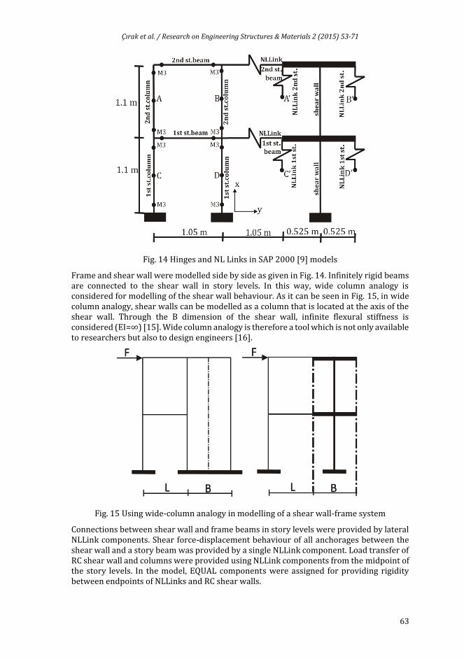
Fig. 14 Hinges and NL Links in SAP 2000 [9] models
Frame and shear wall were modelled side by side as given in Fig. 14. Infinitely rigid beams are connected to the shear wall in story levels. In this way, wide column analogy is considered for modelling of the shear wall behaviour. As it can be seen in Fig. 15, in wide column analogy, shear walls can be modelled as a column that is located at the axis of the shear wall. Through the B dimension of the shear wall, infinite flexural stiffness is considered (EI=∞) [15]. Wide column analogy is therefore a tool which is not only available to researchers but also to design engineers [16].
Fig. 15 Using wide-column analogy in modelling of a shear wall-frame system
Connections between shear wall and frame beams in story levels were provided by lateral NLLink components. Shear force-displacement behaviour of all anchorages between the shear wall and a story beam was provided by a single NLLink component. Load transfer of RC shear wall and columns were provided using NLLink components from the midpoint of the story levels. In the model, EQUAL components were assigned for providing rigidity between endpoints of NLLinks and RC shear walls.

Çırak et al. / Research on Engineering Structures & Materials 2 (2015) 53-71
64
EQUAL constraint makes sure that the located place in the chosen degree of freedom moves with same amount of displacement. A, B, C and D points define the mid points of the story levels. These points displace along with A’, B’, C’, D’, owing to EQUAL constraint.
Hinges were defined at the endpoints of beams and columns. Flexural capacity of shear wall component was calculated and is considered in nonlinear model. For representing hinging in the endpoint of shear wall, NLLink components were used. Moment-curvature relationship belonging to shear wall was obtained by using SEMAp [17] software which was developed for modelling nonlinear behaviour of reinforced concrete components.
Moment–rotation behaviour of external shear wall was modelled with an idealization as given in Fig. 16. Obtained moment-curvature relationship was transformed into moment–rotation behaviour. Elastic rotation during yielding and plastic rotation in hinge can be calculated respectively with Eqn.6 and Eqn 7.
(6)
(7)
In these equations, is yielding rotation; is yielding curvature; is rotation
capacity of plastic hinge, is the ultimate curvature, is size of plastic hinge.
Fig. 16 Moment-rotation relationship which was calculated for shear wall component
In columns located on endpoint of shear walls, besides anchor damage, columns can fail under axial load and rupture of steel reinforcement by tensile forces is possible. For that reason, compressive and tensile strength capacities of columns were considered in nonlinear model.
4.2 Comparison of Experiment and Analyses Results
The suggested model and reduced values with ACI 318 [11] formulation for SAP2000 [9] results are given for comparison with experimental values in Figs. 17-18. Modified model with ACI 318 [11] capacity values, have lower capacity due to reductions made for possible concrete failure. An amount of decrease in capacity was observed in all models after reaching lateral load capacity. This decrease indicates that capacity of anchors have started
pyy
pyup )(
y y p
u p

Çırak et al. / Research on Engineering Structures & Materials 2 (2015) 53-71
65
to decrease. In Figs. 17-18, the continuous line named as “Monolithic Behaviour” represents the case of shear wall with full capacity reflecting the monolithic behaviour with the frame. The reduction in capacity due to connection with anchors is obvious in figures. The red dotted lines in the figures represent the suggested model modified for concrete failure using ACI 318 strength values as upper bound.
Fig. 17 Envelope curves of C1 and C2 test specimens and capacity curves of SAP 2000 [9]
Differences in lateral load-displacement curves which were obtained as a result of experiments and analytical studies can be related with applied cyclic load during experiments. In the analyses, the mentioned load pattern is applied in a monotonically increasing manner and the rigidity loss is not directly taken into account.
Maximum load and collapse damages obtained in SAP 2000 [9] models for all of the frames, strengthened with external shear wall, are seen in Figs. 19-30. The black dots represent heavy damage and failure at the corresponding points.

Çırak et al. / Research on Engineering Structures & Materials 2 (2015) 53-71
66
Fig. 18 Envelope curves of C3 test specimens and capacity curves of SAP 2000 [9]

Çırak et al. / Research on Engineering Structures & Materials 2 (2015) 53-71
67
Fig. 19 Maximum load and component damages in case of collapsing for C1DE model
Fig. 20 Maximum load and component damages in case of collapsing for C2ED model
Fig. 21 Maximum load and component damages in case of collapsing for C2AA model
Fig. 22 Maximum load and component damages in case of collapsing for C2BA model

Çırak et al. / Research on Engineering Structures & Materials 2 (2015) 53-71
68
Fig. 23 Maximum load and component damages in case of collapsing for C2BB model
Fig. 24 Maximum load and component damages in case of collapsing for C2DA+ model
Fig. 25 Maximum load and component damages in case of collapsing for C3HD model
Fig. 26 Maximum load and component damages in case of collapsing for C3DH model
Fig. 27 Maximum load and component damages in case of collapsing for C3DG model

Çırak et al. / Research on Engineering Structures & Materials 2 (2015) 53-71
69
Fig. 28 Maximum load and component damages in case of collapsing for C3EE model
Fig. 29 Maximum load and component damages in case of collapsing for C3AA model
Fig. 30 Maximum load and component damages in case of collapsing for C3BA model
5. Results and Discussion
In this study, finite element models of two-story, one-bay RC frame specimens strengthened with external shear walls in Pamukkale University Earthquake and Construction Technology Research Laboratory were performed using SAP 2000 [9] software. In these models; nonlinear behaviour of anchors connecting RC shear wall and existing frame is represented with suggested anchor shear model. Reliability of suggested anchor shear model was tested upon these models. It is observed that, experiment results and nonlinear static pushover results are in consistence. As a result of these comparisons, suggested anchor shear model may be used for modelling shear behaviour of anchors.
Authors emphasize that, in developing process of this model, experimental data of anchors which are sufficiently away from edge were used. But there may be some cases that, anchors embedded close to the free edges, defected concrete existence in the place where the anchors are embedded or anchors reach breakout or pryout failure capacity. All of these factors were considered and lateral load-displacement capacities obtained by using suggested anchor shear model were bounded by the ultimate loads obtained from the formulas in ACI 318 [11].
In case of a compressive strength higher than 20 MPa and with reasonable amount of anchors, it was seen that suggested model and single diecast shear wall are closer compared to others. But, in case of a compressive strength under 20 MPa, capacities obtained by considering both cases were nearly the half of single diecast shear wall.
Çırak et al. / Research on Engineering Structures & Materials 2 (2015) 53-71
70
Therefore, anchors reach their capacity with steel damage due to the increase of concrete compressive strength. Also, it can be stated that concrete compressive strength of existing structure is very important when calculating shear capacity. In specimens, the least value for concrete compressive strength is 5 MPa. Thus, use of this model in structures that has concrete compressive strength under 5MPa is not suggested because it is not in scope of the study.
Acknowledgements
This study has been supported by the Turkish Scientific Resesarch Council (TÜBİTAK) through Project No. 107M572 and Suleyman Demirel University (SDU) through Project No. 1458-D-07, BAP. Authors sincerely thank TÜBİTAK and SDU for their contributions. Additionally, authors are grateful to the staff of Pamukkale University Earthquake and Construction Technology Research Laboratory due to their contributions in the experimental study.
References
[1] Altın S, Anıl Ö, Kara ME. Strengthening of RC nonductile frames with RC infills: An experimental study. Cement & Concrete Composites, 2008; 30: 612–621. http://dx.doi.org/10.1016/j.cemconcomp.2007.07.003
[2] Thorat SR, Salunke PJ. Seismic behaviour of multistorey shear wall frame versus braced concrete frames. International Journal of Advanced Mechanical Engineering, 2014; 4: 323-330.
[3] Erdem İ, Akyüz U, Ersoy U, Özcebe G. An experimental study on two different strengthening techniques for RC frames. Engineering Structures, 2006; 28: 1843–1851. http://dx.doi.org/10.1016/j.engstruct.2006.03.010
[4] Moehle JP. State of research on seismic retrofit of concrete building structures in the US. US-Japan Symposium and Workshop on Seismic Retrofit of Concrete Structures-State of Research and Practice, USA, 2000.
[5] Türk M, Ersoy U, Özcebe G. Sysmic rehabilitation of RC frames with RC infill walls. Fifth national conference on earthquake engineering, No: AT-045, İstanbul, 2003.
[6] Pujol S, Fick D. The test of a full-scale three-story RC structure with masonry infill walls. Engineering Structures, 2010; 32: 3112-3121. http://dx.doi.org/10.1016/j.engstruct.2010.05.030
[7] Özen MA, Yılmaz S. Tensile performance of retrofitting anchors. Second European Conference on Earthquake Engineering and Seismology, İstanbul, Aug. 25-29, 2014.
[8] Çırak İF. Modelling shear behaviour between strengthening shear walls and existing structural elements. Ph.D Dissertation, Süleyman Demirel University, Isparta, 2011.
[9] SAP 2000. Integrated finite element analyses and design of structures. Computers and Structures Inc, Berkeley, USA.
[10] Görgülü T. Application of external steel construction shear wall at strengthening of the present structure. Ph.D. Dissertation, Süleyman Demirel University, Isparta, 2008.
[11] ACI 318–05. Building Code Requirements for Reinforced Concrete. American Concrete Institute, Detroit, USA, 2005.
[12] TS 500. Requirements for design and construction of reinforced concrete structures. TSE, 2000.
[13] Yılmaz S., Çetinkaya N., Çalışkan Ö., Çırak İ.F. Experimental investigation on anchor applications for external shear walls. Technical Report No: 107M572, Denizli, 2010.
[14] Çalışkan Ö. Experimental study of anchor application on the existing reinforced concrete structures strengthened with external shear walls. Ph.D. Dissertation, OGU, Eskişehir, 2010.
Çırak et al. / Research on Engineering Structures & Materials 2 (2015) 53-71
71
[15] Atımtay E. Design of frame and shear-wall RC structures. METU, Ankara, 2000; 2: 746, 2000.
[16] Beyer K, Dazio A, Priestley MJN. Inelastic wide-column models for u-shaped reinforced concrete walls. Journal of Earthquake Engineering, 2008; 12: 1–33. http://dx.doi.org/10.1080/13632460801922571
[17] Inel M, Ozmen HB, Bilgin H. Modeling non-linear behaviour of reinforced concrete members, TUBITAK, Project No: 105M024, 2008.
[18] Cook RA. Behaviour of chemically bonded anchors. Journal of Structural Engineering, ASCE, 1993; 119: 2744-2762. http://dx.doi.org/10.1061/(ASCE)0733-9445(1993)119:9(2744)
[19] McVay M, Cook RA, Krishnamurthy K. Pull-out simulation of post installed chemically bonded anchors. Journal of Structural Engineering, 1996; 122: 1016-1024. http://dx.doi.org/10.1061/(ASCE)0733-9445(1996)122:9(1016)
[20] Ožbolt J, Eligehausen R, Reinhardt HW. Size effect on the concrete cone pull-out load. International Journal of Fracture, 1999; 95: 391–404. http://dx.doi.org/10.1023/A:1018685225459
[21] Alqedra MA, Ashour AF. Prediction of shear capacity of single anchors located near a concrete edge using neural networks. Computers & Structures, 2005; 83: 2495-2502. http://dx.doi.org/10.1016/j.compstruc.2005.03.019
[22] Turkish earthquake code specifications for buildings to be built in seismic areas. Ministry of Public Works and Settlement, Ankara, 2007.
[23] Çalışkan Ö, Yılmaz S, Kaplan H, Kıraç N. Shear strength of epoxy anchors embedded into low strength concrete. Construction and Building Materials, 2013; 38:723-730. http://dx.doi.org/10.1016/j.conbuildmat.2012.09.020
[24] Kaplan H, Nohutcu H, Çetinkaya N, Yılmaz S, Gönen H, Atımtay E. Seismic strengthening of pin-connected precast concrete structures with external shear walls and diaphragms. PCI Journal, 2009; 54: 88-99. http://dx.doi.org/10.15554/pcij.01012009.88.99