Embed Size (px)
Citation preview
Purdue UniversityPurdue e-Pubs
Computer Science Technical Reports Department of Computer Science
1981
A Model for Representing Families of ProgrammedSystemWalter F. Richy
Report Number:80-356
This document has been made available through Purdue e-Pubs, a service of the Purdue University Libraries. Please contact [email protected] foradditional information.
Richy, Walter F., "A Model for Representing Families of Programmed System" (1981). Computer Science Technical Reports. Paper 287.http://docs.lib.purdue.edu/cstech/287
A Model for Representing Families of Prograrrmed System
by
\1alter F. Tichy
Computer Science Department
Purdue University
West Lafayette, Indiana ~7907
CSD-TR 356
A Model for Representing Families of ProgrammedSystems
Walter F. Tichy
Depar.tment of Computer SciencesPurdue University
West Lafayette. Indiana 47907
ABSTRACT
A general model for multi-version, multipconfiguration pro
grammed systems is presented. It is used to evaluate the data
repres~ntaLlOnsunderlying various programming support environ
ments. The model is based on AND/OR graphs and allows the com·
pact description of system families. The hierarchical model, the
rel,ational model" and the sequenti.al release modeL are defined as
subclasses of the general model. It is shown that the hierarchical
and relational representations are e3sentially the same.
The concept of the well-formed configuration is developed as
a rcfin"lment of the general model. This concept yields the basic
rules for inlerface conLrol and configuraLion c.:ornposilion. The
model is also employed to stale basic requirements for the data
ba~es all which programming support environments should be
bunt.
,January 0, 1901
A Model for Representing Families of ProgrammedSystems
Walter F. Tichy
Department of Computer SciencesPurdue University
West Lafayette. Indiana 47907
1. Introduction
Programming support environments (PSE's) have recently been stressed as
a way to significantly improve software production methods and software quality
[Ker79a, Hab79a, BuxBOa, RidBOa]. A PSE provides a rich set of sophisticaLed
tools that support or automate various tasks during software development and
maintenance. An important feature of a successful PSE is that il is well coordi
naLed Ivith a high-level programming language, so that the PSE and the language
complement and enhance each olher.
Unfortunately, rese::arch in PSE's has not kept pace with advances in pro
gramming languages. This is vividly demonstrated by comparing lhe following
two recent documents: The requirements for the Ada programming language
[DoD77a] are specific and precise, whereas the requirements for the Ada pro
gramming support environment [BuxBOb] are qUite the opposite. There is an
impressive body of knowledge about programming language concept!:>, docu
mented in numerous books, journals, and conference proceedings (see, ror
example [Els?3aJ). In contrast. there is not nearly as much quality material
published on software development environmrmts (Unix [Ker79a] being a notable
exception). We do noL want to argue here why this is SO, but the conclusion
should be obvious: If we want to tackle the software crisis by means of program-
ming support environments, we are in desperate need of useful concepts related
to them. We need concepts for modeling. classification. and evaluation. and we
need to come up wilh new ideas and prototypes. This paper makes a start in
thaL direction by presenting a model which can be used lo compare the data
representations underlying a wide range of programming support tools and
-z-
environments, as well a.s providing a suitable conceptual basis for further
research and development. The model is noL ltmited to software. but can be
applied to hardware. firmware. documentation, and test configurations as well.
Before we discuss our model in detail. let us make two observations con
cerning programming environments. First. a common way of introducing a par·
ticular environment is to explain how to write and run a program or how to
prepare a document. Thus, the environment is described by the functions it
performs. The datu structures involved are hardly mentioned, because they are
usually simple text files. We take a different approach. We shall first discuss the
data sLructures tor representing programmed systems, and then the operations
for manipulating lhem. The reason is thflt the data structures delermine Lo a
large degree what kinds of systems can be handled at all. We shall see that most
existing PSF;'s severely constrain the structure of the systems they can handle
efTedively.
The second observation concerns the phenomenon that all software systems
evolve into famlUes of related versions and c..:Jnligurations, a fact Widely ignored
by existing support environments. A few examples of system families are in
order. Compilers are typically ported to different environments, resulting in
large families. Consider, for instance, Pascal [Wir71a] and C [Ker7Ba], which are
available on a wiufl range of architectures. The same is beginning to happen to
some operating systems: Versions of UNIX [Ker79a] and Thoth [Che79a] run on
significantly different machines. The portability of programs and, in particular,
of soFlwnrc tools is also a major goal of the Ada language and support efforts
[BuxBOb]. Howflver, it is naive to assume that a program will execute correctly
in every environment as long as it is written in a portable language. In reality.
all kinds of minor and major changes are necessary, causing a single system to
branch out inlo many parallel versions.
The porting of programs to different environments is not the only cause for
multiple versions. Repair, enhancement, and customization ure additional ones
[Ben9al. Of lhese, repair seems to be the easiest one to deal with: If a particu
lar version i~ caneeled. one can safely thro·w away the old one. UnfortWlately,
this is not so if a larg·e user community has come to depend on the old version,
- 3 -
forcing a system's administrator to maintain. "obsolete" versions.
Enhancement and cuslomization are powerful forces that cause new ver
sions to arise almost spontaneously. Users always seem to apply a given system
in unexpected ways or unforeseen situations, adding improvements, bells and
whistles. ilnd frequently changing the characteristics of a system. And so the
modification cycle goes on.
An obvious approach to the problems of multiple versions is to eliminate
them altogether. Unfortunately, this is not a viable approach. System familles
arise in response to widely differing demands. We shall never be able to write the
aU-encompassing compiler. operating system. telecommunications system,
weapons system, etc., that will adequately serve the whole user community
[Par79a]. On the other hand, the ad hoc approach of constructing a new, unique
program for every user group is too costly. We need to economize by building
system famuies whose members shars common parts. In other words, we need
to learn how to deal effectively with system families.
The existence of system families has long been acknowledged by Parnas and
olhers [Par7f)a, Par79a, Hab76a. Coo7Ba. Lo"BOa]. Unfortunately, all current pro·
gramming language designs and most existing PSE's still ignore or ~kjrt the
issue of multiple versions. This will become more obvious in Section 3.
2. A General Model for Representing Families of Progrwnmed Systems
At the heart of any programming support environment must be some model
of the structure of the system that is to be developed and maintained. The
model determines to a large degree what kinds of tools can be applied to what
kinds of systems. We present a general model for multi-version, multi
conftguration system families, which has the follOWing properties:
a) Multiple versions: ConOgurations as well as primitive components may be
represenLed in any number of versions.
- 4-
b) Sharing: Conflgurations as well as primitive components may be shared
amanA other configurations without restriction. Thjs applies to individual
versdon:=; flS well as groups of versions.
c) CompleLeness. All versions of all configurations and primitive components
may be represented in a compact form.
d) Generality: Hardware, firmware, software, documentation, test data. etc.,
a.nd versions t.hereof, can all be combined into configurations. (This is a
consequence of c).)
e) Well-Formed ConOguration: As a refinement, the concept of a well-formed
configuration is defined with respect to the interfaces associated with the
components.
The model can also be used to evaluate the representations tulderlying
existing programming support environments (see Section 3).
2.1. Introduction to the Model
Our model is based on AND/OR graphs. AND/OR graphs are applied in prob~
lem solving methods in Artificial Intelligence [Nil71a] and for analyzing serial
action work in industry [Rig69a]. However. AND/OR graphs will be used quite
differenLly here.
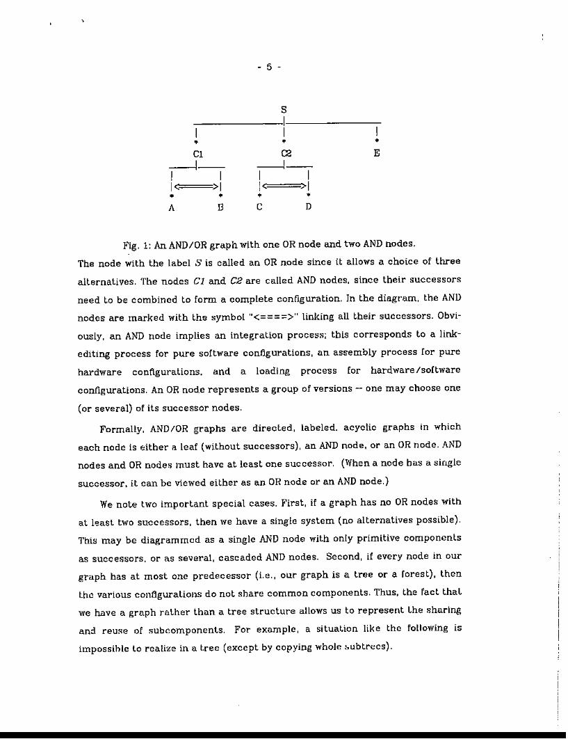
Suppose we have a ~ystem S with three configurations C1, C2, and E. Sup
pose furthermore that configuration C1 consists of components A and B,
configmation C2 of components C and D, and configuration E is primitive (i.e .. a
sinp,le componenL). This situation can be diagrammed in the following way (see
Fig. 1).
- 5 -
s11
• • •Cl C2 E
---1- ---I-I 1 1 11< >1 1< >1• • • •A D C D
Fig. 1: An AND/OR graph with one OR node and two AND nodes.
The node with the label S is called an OR node since it allows a choice of three
alternatives. The nodes Cl and C2 are called AND nodes, since thelr successors
need to be combined to form a complete confJ.guration. In the diagram, the AND
nodes are marked with the symbol "<=====>" linking all their successors. Obvi
ously, an AND node implies an integration praces:,,; thls corresponds to a link
editing process for pure software configurations, an assembly process for pure
hardware configurations. and a loading process for hardware /soflware
configurations. An OR node represents a group of versions -- one may choose one
(or several) of its successor nodes.
Formally. AND/OR graphs are directed, labeled. acyclic graphs in which
each node is either ii leaf (without successors), an AND node, or an OR node. AND
nodes and OR nodes must have at least one successor. (When a node has a single
successor, it can be viewed either as an OR node or an AND node.)
We note two important special cases. First, if a graph has no OR nodes with
at least two successors, then we have a single system (no alternatives possible).
This may be diagrammed as a single AND node with only primitive components
as successors, or as several, cascaded AND nodes. Second, if every node tn our
graph has at most one predecessor (Le., our graph is a tree or a forest), then
the various configurations do not share common components. Thus, the Fact thaL
we have a graph rather than a tree structure allows us to represent Lhe sharing
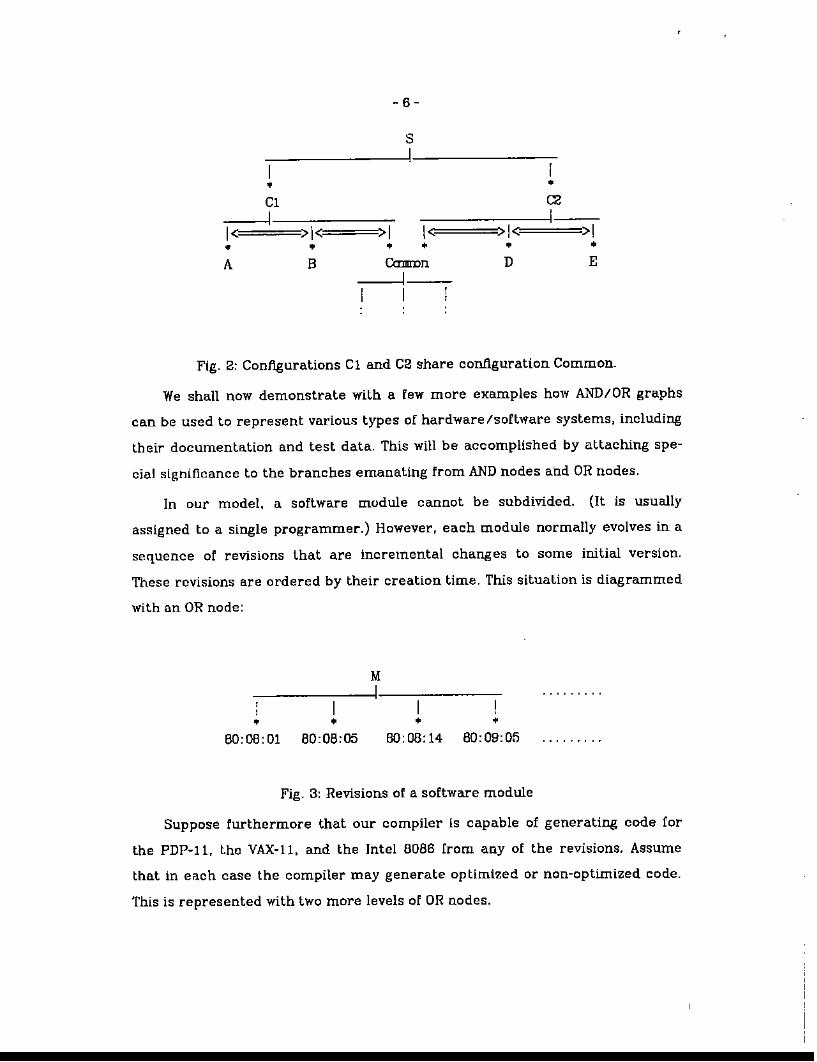
and reu:::e of subcomponents. For example, a situation like the fallowing is
impossihle to realize in a tree (except by copying whole ~ubtrecs).
-6-
s1
•C11
1< >1< >1 1<• • • •A B CamIDn
11
I•C21
>1< >1• •D E
Fig. 2: Contlgurations Cl and C2 share configuration Common.
We shall now demonstrate with a few more examples how AND/OR graphs
can be used to represent llariOUli types of hardware Isoftware systems, including
their documentation and test data. This will be accomplished by attaching spe
cial slgnificance to the branches emanating from AND nodes and OR nodes.
In our model. a software module cannot be subdivided. (It is usually
aSSligned to a single programmer.) However, each module normally evolves in a
sequence of revisions that are incremental changes to some initial version.
These revisions are ordered by their creation time. This situation is diagrammed
with an OR node:
,,•
1
•
M1
1
• •60,08,01 60,06,05 60,06,14 60,09,05
Fig. 3: Revisions of a software module
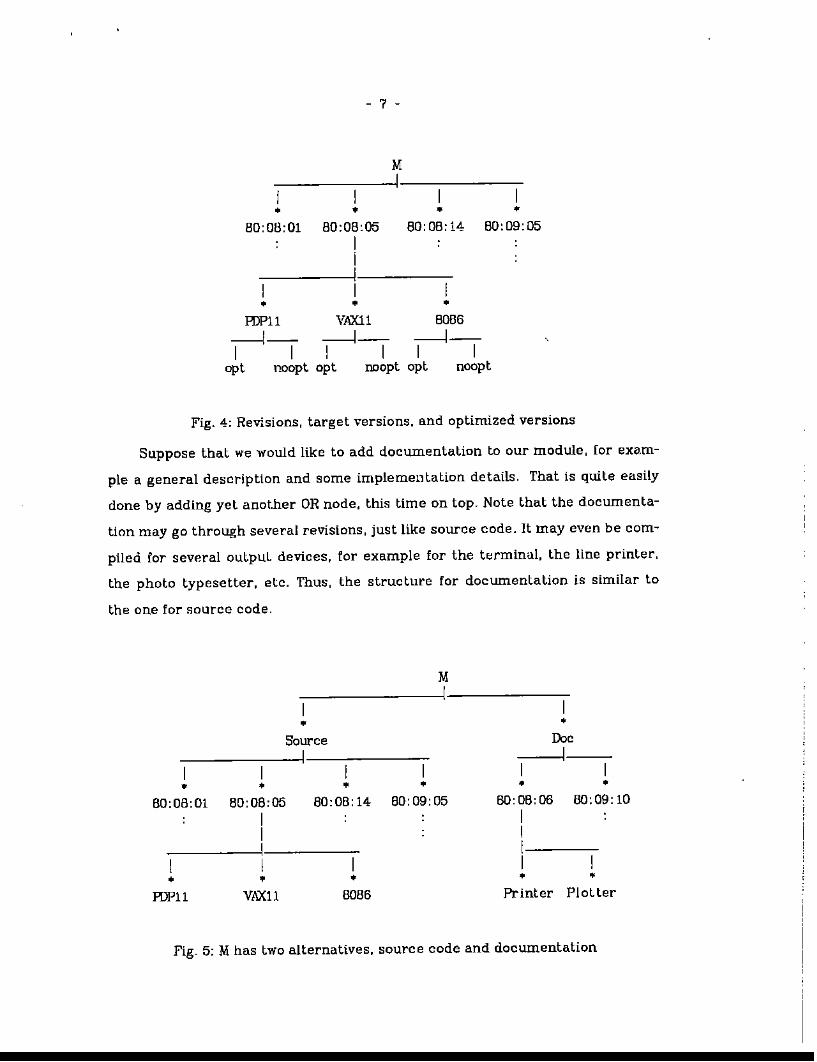
Suppose furthermore that our compiler is capable of generating code for
the PDP-H, the VAX-ll. and the Intel 8086 from any of the revisions. Assume
that in each case the compiler may generate optimized or non-optimized code.
This is represented with two more levels of OR nodes.
- 7 -
MI
I I I• • • •
80:08:01 80:08:05 80: OB: 14 80:09:05IiII I
• • •HJP11 VAX11 8086
-----J- -----J- -----J-I I I I I I,
opt noopt opt noopt opt noopt
Fig. 4: Revisions, target versions. and optimized versions
Suppose that we would like to add documentation to our module, [or exam
ple a general description and some implementation details. That is quite easily
done by adding yet anot.her OR node. this lime on top. Note that the documenta
tion may go through several revisions, just like source code. It may even be com
piled for several outpuL devices. for example for the terminal, the line printer,
the photo typesetter. etc. Thus, the structure for documentation is similar to
the one for source code.
M-,---------1------,-
• •
I• •
80:08:01 80:08:05III
HJPll VilXll
•
80:08:14 80:09:05
I•
8086
•DocI
• •80: 08: 08 80:09: 10
II1
I• •
Printer Plotter
Fig. 5: M has two alternatives, source code and documentation
- B -
Clearly, an OR branch for documentation can be added wherever desirable.
For example, one may add documentation to the revisions in the form of e.
"change log." One can also associate documentation with higher-level nodes to
supply a general overview, a user's manual, or the requirements specHication.
Since the Sf!mantics of an OR node are to choose at least one successor, we can
even. model the view that a program and its documentation form an entity.
1t. should be clear that the AND/OR graph can be applied to hardware as
well. The decomposition into subgraphs may. however, have somewhat different
appearances. For example, there may be components that have no revisions,
like scrt3ws or other :;;tandard parts. There, may also be additional documents,
Hke circuit schematics or instructions for the assembly of certain
configurations.
Hy~)rid configurations consisting of both hardware and software are best
represented with AND nodes. For instance. if a particular program is to be
stored in a specific PROM. then both components should be successors of the
same AND node. A combination of hardware and software is permissible any
where in the graph. For instance, we may want to indicate that a certain operat
ing system can run on several machine models, or that some software com
ponents have to be distributed over specific nodes in a netwDrk. This can all be
managed with AND/OR graphs.
2.2. 'J1:tc Selection Problem
A single AND node may actually represent a number Df pOSSible
configurations if some of its successors are OR nodes. This leaves us with the
problem of selecting a speCific configuration. CDnsider the following example.
- 9 -
•Terminal
•
put1
>1•
•
I•
lPT(defau[ t)1
1< >1<-• •
open close, 11
• • • • • •1.1 1.5 2.3 1.2 2.2 3. I VAX(default) PDP11
-1- ---I-I 1 1 I 1• • • • •
IO
.,----------11------,-
1.1 1.5 1.1 2.1 3.1
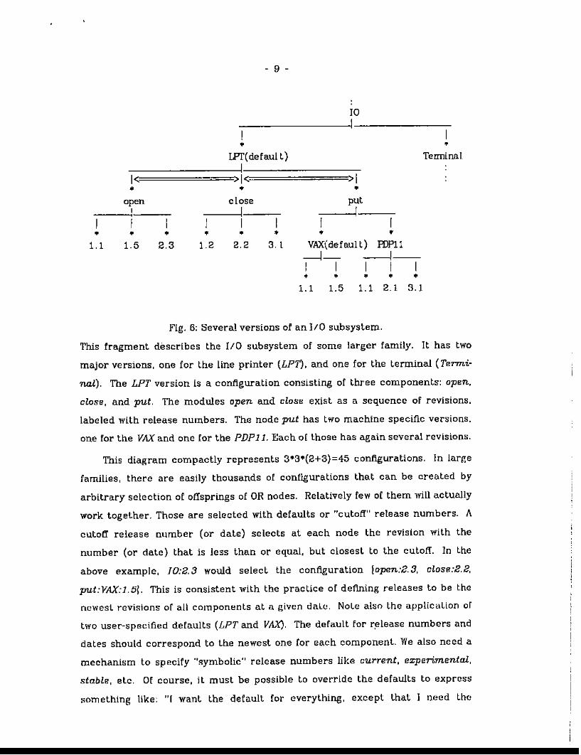
Fig. 6: Several versions of an 110 subsystem.
This fragment describes the 110 subsystem of some larger family. It has two
major versions, one for the Une printer {LPn, and one for the terminal (Termi
nal). The LPT version is a configuration consisting of three components: open,
close, and put. The modules open and close exist as a sequence of revisions.
labeled with release numbers. The node put has two machine specific versions.
one for the VAX" and one for the PDP11. Each or those has again several revisions.
This diagram compactly represents 3·3·(2+3)=45 configurations. In large
families, there are easily thousands of configurations that can be created by
arbitrary selection of offsprings of OR nodes. Relatively few of them will actually
work toget.her. Those are selected with defaults or ..cutoff" release numbers. A
cutoff release number (or date) selects at each node the revision with the
number (or date) that is less than or equal, but closest to the cutoff. 1n the
above example, JO:2.3 would select the configuration lapen:2.3, clase:2.2,
put:VAX:l.5!. This is consistent with the practice of defining releases to be t.he
newest revisions of all components at a given dalC;!. Nole also the appUcaLlon of
two user-specified defo.ults (LPT and VAX). The default for r.elease numbers and
dates should correspond to the newest one for each component. We also need a
mechanism to specify "gymbolic" release numbers like current, experimental,
stable, etc. Of course, it must be possible to override the defaults to express
something like: "I want the default for everything, except that I need the
- 10 -
Terminal-version of [0." This is expressed with 10. Terminal. Notations for cas
catllng those selections are easily invented.
An additional selection mechanism involves the labeling of DR branches.
The labels can then serve as criteria for global selection. For example, suppose
that some of the branches emanating rrom OR nodes are labeled basic, inter
mediatv., or advanced, indicating the obvious qualities about the three choices.
Assume that these labels are spread through a large graph. Then one can select
a Jcsired configuration by ~imply requesting, [or instance. the basic branch
wherever there IS a choicc. (Note that this is similar to the global selection by
cul.off date.) This technique is also convenient for specifying the target machine
or optimized/unoptimized versions. An example is JO:PDP11:nonopt.
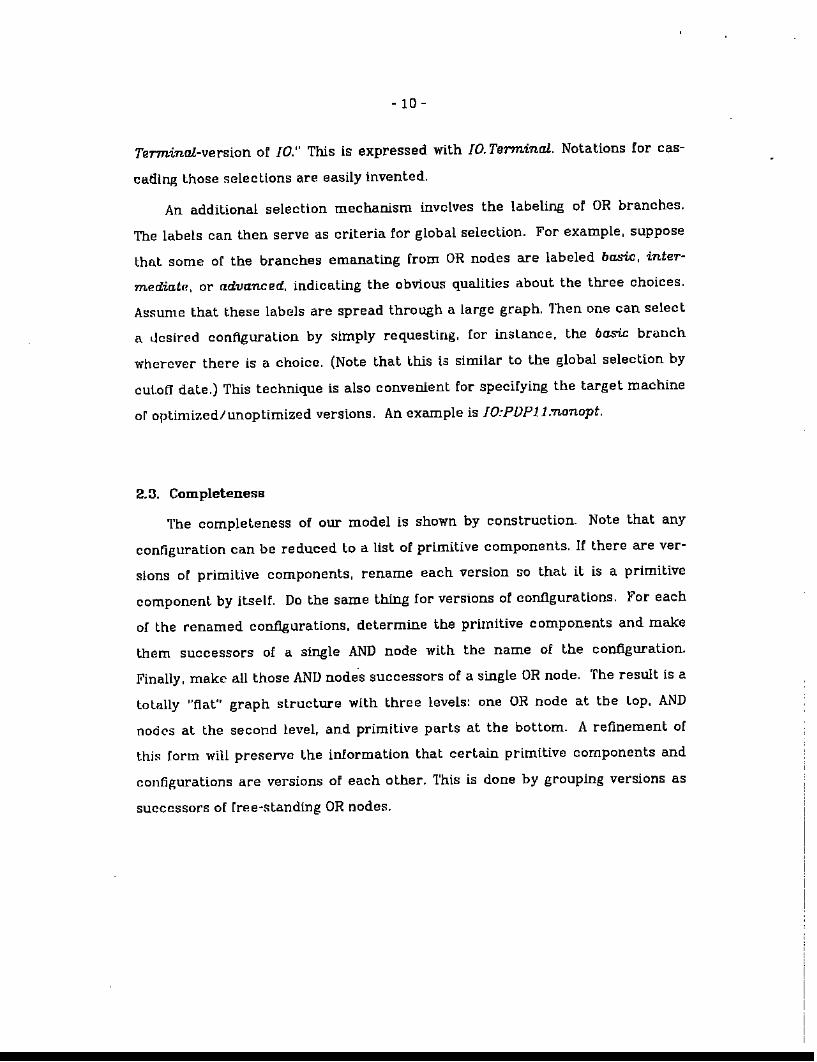
2.3. Completeness
The completeness of our model is shown by construction. Note that any
configuration can be reduced to a list of primitive componl:!nts. If there are ver
sions of primitive components, rename each version so that it is a primitive
component by itself. Do the same thing for versions of configurations. For each
of the renamed configurations. determine the primitive components and make
them successors of a single AND node with the name of the configuration.
Finally, make all those AND nodes successors of a single OR node. The result is a
totally "flat" graph structure with three levels: one OR node at the Lop. AND
node'S at the second level. and primitive parts at the bottom. A refinement of
this form will preserve the information that certain primitive components and
configurations are versions of each other. This is done by grouping versions as
successors of rree·standing OR nodes.
- 11 -
1 1Cl C2I 1
-;---:-~I--,----c 11=1=>1=>1 1=1=PI P2 P3 P4 P5
10P1
=>1Pp
IenI
Fig. 7: Normal form for representing all configurations.
2.4. Yell-Formed Configurations
A refinement of our model yields the concept of the well·!onned
configuration. This concept is defined in terms of the interfaces between the
components of a configuration. It forms the foundations for interface control
and system composition. Interface control is important in multi-person projects
for establishing and maintaining consistent interfaces between components.
System composition is the activity of building new configurations from existing
components. Our concept is a generalization of the conditions on system struc
ture presented in [TicBOa] and [HabBOa].
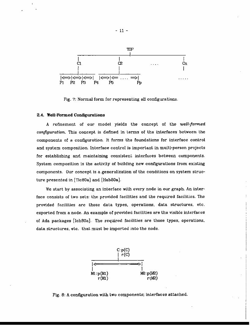
We start by associating an interface with every node in our graph. An inter
face consists of two sets: the provided facilities and the required facilities. The
provided facilities are those data types. opl:'rations, data structures, etc.
exported from a node. An example of provided facilities are the visible interfaces
of Ada packages [lchBOa]. The required facUities are those types, operations.
data structures, etc. that must be imported into the node.
1<1
Ml,p(Ml)r(M1)
C,p(C)1 r(C)I
>1I
Ma,p(M2)rtM2)
Fig. B: A configuration with two components; interfaces attached.
- 12-
The set of facilities provided by a node N is denoted as p(N). the set of
required facilities as r(N) .... We have to 'muke sure that a faciHLy mentioned in
the provided set of a node does not also occur in the required set. This leads to
thE: following definition.
A node N is fTee of contradictions if and only if
peN) n r(;<) =¢
We define two nodes to be compatible if they have the same interface:
Two nodes, Nand M, are compa.tible if and only if
peN) =p(M) and r(N) =reM)
This definition applies to arbitrary nodes; it will be especially interesting for
nodel'l th.at are successors of the same OR node. Compatible nodes are fully
interchangeable.
Similarly, we define node M to be upward compatible with node N if M pro
vides at least what. N pcovides, and requires not more than what N does. That
means that:M can be used instead of N, bu~ not vice versa.
Node M is upward. compalible with node N If and only if
p(M) 2 peN) and reM) <: r(N)
• We COllid link the interfaces into our diagram with some extra OR nodes, but that '/I'oWdonly clutler the pictUl'e.

- 13 -
We can now define weU-foTTned nodes. There are dU'[erenl (recursive)
definitions for each node type (leaf, AND. and DR nodes).
A. A leaf node is well-formed if and only if it is free of contradictions.
(Since a leaf node usually corresponds to a given source module. we have to
makp. sure that the source actually satisfies the interface. Techniques for
implementing that have been presented in [Tic79a].)
B. An OR node R with direct successors Kl, ...Kn (~1) is well-formed if and only
if
i. R is free of contradlctions:
ii. There exists a direct successor Ki (lsiS"n) of R which is welHormed and
upward compatible with R.
(Since only one Ki needs to satisfy condi.tion ii. we can add documentation
to OR nodes without problem, or make configurations versions of each other,
although they have different interfaces.)
C. An AND node S with direct successors Kl. ...Kn (~l) is well-formed if and
only if
i. S is free of contradictions;
iL All Ki (l:!!ii$;n) are well-formed;
iii. p(Ki) n p(Kj) =¢ if i :;I! j (freeness of conflicts)
n
i,. p(S) ~ U p(Ki)\=1
n nV. r(S) 2 (U r(Ki) - U p(Ki))
\=1 \=1
Since configurations correspond to AND nodes. we say that a configuration
is well-formed if its AND node is well-farmed.
The basic conditions given above are precisely those which must be
checked when a configuration ls built from a set of components. The conditions
can also be used to construct the interfaces of newly created AND nodes and OR
nodes H a system designer is composing new system versions. They are applied
- 14-
in search algorithms that compose well-formed configurations automatically.
The interfaces can also be used to assess proposed interface changes byanalyz
ing the effects for each node. Finally. interface changes can be carried out by
propagating the modifications to all affected nodes, as described in [Tic79a].
In summary, AND/OR gl"aphs provide a basis for the compact representa
tion of all versions of -all posslble contlguralions in a system family. Individual
versions can be selected by specifying a few parameters and defaults. The con
cept of well-formed configuration is important for the system designer and
yields the basic rules for interface control and system composition.
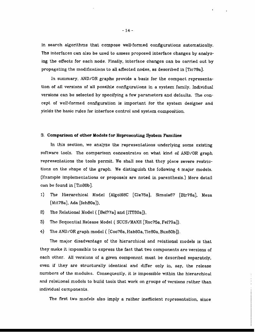
3. Comparison of other Models for Representing System Families
Tn this section, we analyze the representations underlying some existing
software tools. The comparison concentrate'i:l on what kind of AND/OR graph
representations the tools permit. We shall see that they place severe restric
tions on the ~hape of the graph. We distinguish the following 4 major models,
(Example implementations or proposals are noted in parenthesis.) More detail
can be found in [TicBOb].
1) The Hierarchical Model (Algo16BC [Cle75a], Simula67 [Bir76a]. Mesa
[Mil?Ba]. Ada [lchBOa]),
2) Tho Relalional Model ( [Bel??a] and [lTTBOa]),
3) The Sequential Release Model ( SeeS/MAKE [Roc75a, Fe179a]).
4) The AND/OR graph model ( [Co07Ba. HabBOa, TicBOa, BuxBOb]).
The major disadvantage of the hierarchi.::lal and relational models is that
they make it impossible to express the fact. that two components are versions of
each other. All versions of a given component must be described separately,
even if they are structurally identical and differ only in. say. the release
numbers of the modules. Consequently. it i~ impossible within the hierarchical
and relaLional models to build tools that work on groups of versions rather than
individual components.
The first two models also imply a rather inefficient representation. since
- 15-
even the slightest change in a configuration leads to a duplicate description of
the complete configuration. In terms of our general AND/OR graph model, these
limitations are due to the facl that there are no OR nodes in these models.
The sequential release model allows primitive components (modUles) to
exist in a number of revisions. Configllralion~that are structuraUy identical and
whose modules diner only in the revision numbers can be represented with a sin
gle, genL'TlC description. Thus. the problem of having to duplicate large numbers
of configurations for every minor change is avoided. However, it is still not possi
ble to indicate that two slightly dillereol configurations are actually versions of
each other. This is due to the fact that the sequential release model permits no
internal OR nodes.
The general AND/OR graph model on the other hand has none of these res
trictions. Any l"wo configurations can be made versions of each other. and a sin
gle, generic description suffices for structuraily identical configurations. Struc
turaUy similar configurations can be described without dupHcaLion of informa
Lion. Hardware configurations, documentation. test configurations, and lest data
can be added without problem. (None of the examples listed under 4) permits
an AND/OR graph in its full generality.)
3.1. The Hierarchical Model
The hierarchical model is characterized by an AND/OR graph that has no OR
nodes at alL Thus, multiple 'lersions cannot be represented. Each AND node
denotes a single configuration. Every configuration. even if only sHghtly different
from another one, must be described separately. Similarities among
configurations cannot be expressed.
There are two subclasses of the hierarchical model: one is e. strict AND tree,
the other a (loopfree) AND graph. The ANll tree allows no sharing of nodes what
soever. This is a serious problem in large sysLem families because it results in
massive copying and updating problems. However. the AND tree is well suited to
block-structur~d languages: TIle nesting of blocks can be expressed directly
- 16-
with an AND tree. This fact has been exploited in Algo16BC [Cle75a] and Simula67
(Dir76a], where inner blocks can be extracted from a program. compiled
separately, and linked in later. A mechanism that stores intermediate symbol
tables and enforces the scope rules of block structure guarantees that the (sin w
gle) configuration is well-formed.
•
s
~I<-;;;;;;;;;;;;;;;;;;;;;;;;;;;;;;~>I~<;;;;;;;;;;;:-•
>1•
GIl-----.-j-1=>1< >1
1Bl NB2 M23
Gt2-----.-jI<->!=>I
C24 (25 M26
Cln-----.-j1<->1=>1
M27 C2B C29
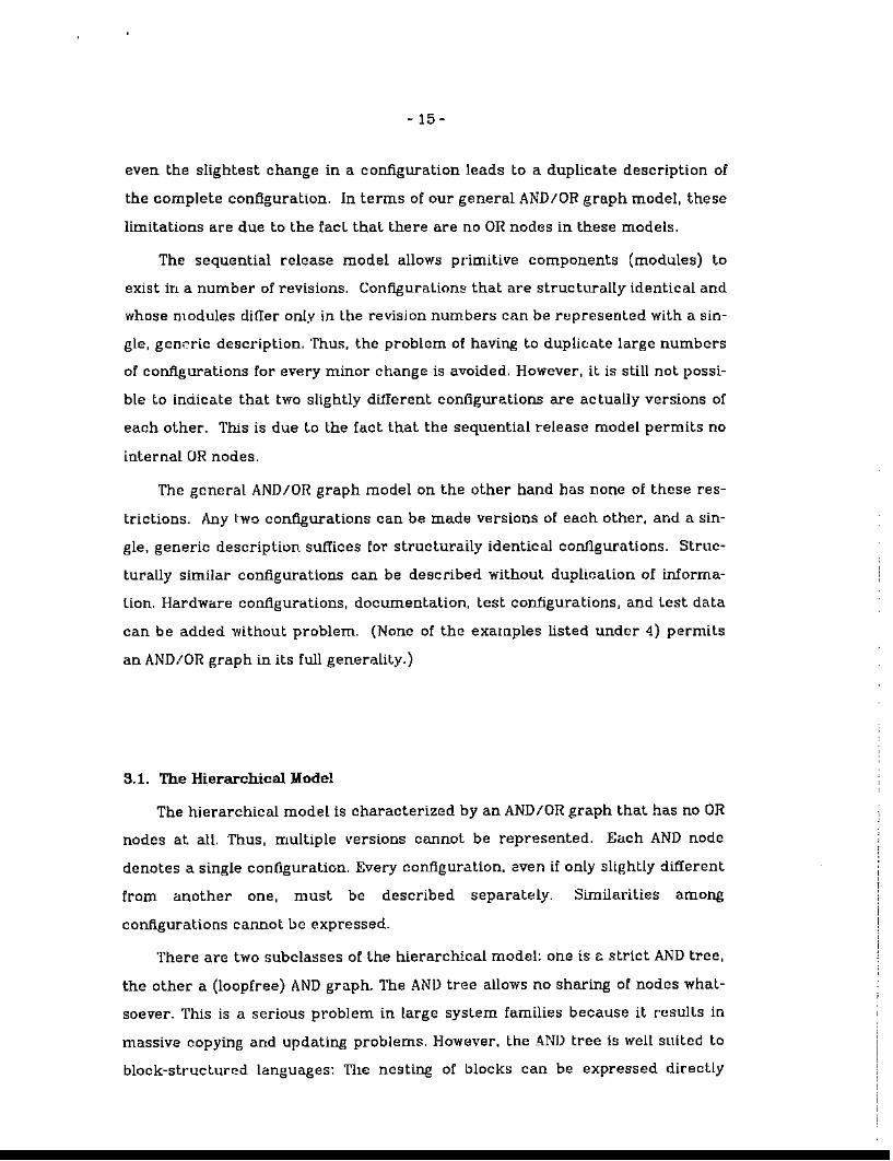
Fig. 9: A fragment of an AND tree.
In the simplest, nontrivial form. the AND tree has two levels: The root is the
name of the configuration, and the second level consists entirely of leaves
(modules). This fOfm it is often used in linker command tiles or in parameters to
compiling and linking commands. Clearly. not much can be done with such a
primitive representation.
The MESA [Mit7Ba] and Ada [lchBOa] languages permit the representation of
AND graphs. This can be used to express the sharing of common components
among several configurations. Elaborate rules on scope and compilation order
ensure well-forrnedness. However, since there are no OR nodes, multiple ver
sions of primitive components and ccnfigurations cannot be described within
these languages. We consider this to be a major flaw of the Ada programming
language.
In all variants of the hierarchical model. change is handled in the following
way. Whenever one of the modules is edited. the new revision replaces the old
one. Saving o[ the old version must happen outside the model. As an example,
consider Ada: the recompilation rules that must be obeyed after a modification
effectivaly' discard all old versions.
- 17 -
A straightforward extension of the hierarchical model is to include compiled
versions of the primitive parts. This is need13d to save recompilation times of
unmodified modules. TIle technique is used in the SDC system [Nol79a), the
MAKE program [FeI79a], and the Mesa language implementation.
This situation can be modeled with our previous AND graph, where the leaf
nodes are replaced with OR nodes. Each OR node has two branches. one for the
source version, the other for the object code version. The object code version is
automatically kept up to dale with the source version.
Note, however. that we have gained nothing besides avoiding redundant
compilations. Since the object code and source version of a single OR node are
essenttally the same, we have nol added an extra degree of freedom. Thus, we
still have the problems of the hierarchical model: {l) no representation of multi
ple versions, (2) duplication of iruormation for nearly identical versions. (3) no
sharing of subsystems in the tree case, and (4) documentation must be handled
separately.
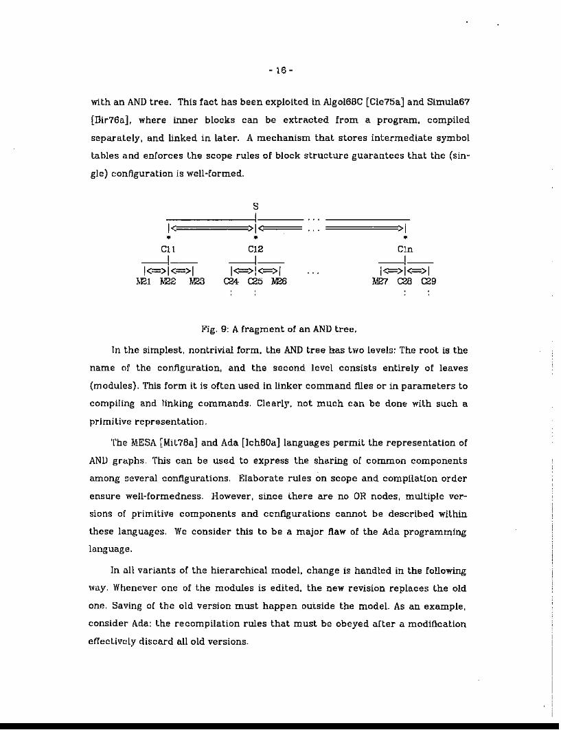
3.2. Th.e Relational Model
A system family with several configurations can be represented using a
boolean matrix:. The primitive components are listed across the top of the
matrix, and the conflgurations down the side. The entry in row i, column j is set
to 1 if and only if part j is included in configuration i.
IMlIM21 IMn----1----1----1------------------- --1----Cl 1 1 I 1 1 I
----1----1----1---------------------1----C2 1 I 1 1 I 1
. ---1----1----1---------------------1----
Fig. 10: A relation with two configurations.
ClearLy. each row can be modeled with a single AND node. The resulting
stru~ture is a fiat graph with 3 levels. The top level is a single OR node, branch
ing out to the AND nodes for the matrix rows. The bottom level consists of the

- 18 -
primitive components. Since these can be shared among several AND nodes. we
have an acyclic graph. not a tree.
I•
FI
I•
C1 C2
----'- ----:;;;;;;;;:;::;;;;;;;;;;i;;1;;;;1< >1 1<= >1•• •M1 Mn
Fig. 11: The relation of Fig. 10 represented as an AND/OR graph.
The probLem with the matrix is that it is huge and sparse. Fortunately, a
few simple refInements can eliminate much of the sparseness (se.e, for example
[BcI77a] and [ITTBOaJ). These refinements involve the placing of version
numbers into the matrix, and a decomposition of the matrix into several rela
tions. However. note that each configuration stands for a single, fixed version.
Generic configurations cannot be entered.
Using our AND/OR graph to analyze the resulting structure, we note that
these refulements lead to a deeper graph of cascaded AND nodes, but no addiw
tional OR nodes besides the one on top. Compare now the hierarchical model.
RecaU that thaL model is characterized with a pure AND graph. If we make all
"free" nodes in that graph (i.e. nodes without predecessor) to successors of a
singh~, artificial OR node, we see that there i.t; no essential difference between
the hierarchical and relational models: they both result in the same AND/OR
graph. This is one of the major conclusions we can draw from the AND/OR
model.
Both the hierarchical and the relational model sutler frOID the fact that
there arc no internal OR nodes. As an example for the kinds of difficulties this
may cause, consider the update problem. Suppose we modify an eXisting source
module M, thereby introducing a new revision M'. To Incorporate the revision, we
have to collecl all configurations that contain M, make copies of them, and
replace M with M' in the copies. If M is a frequently used module, this may result
in nearly doubling the size of the relations or the graph! Since revising
- 19 -
programs happens rather frequently, this representation is clearly unaccept~
able.
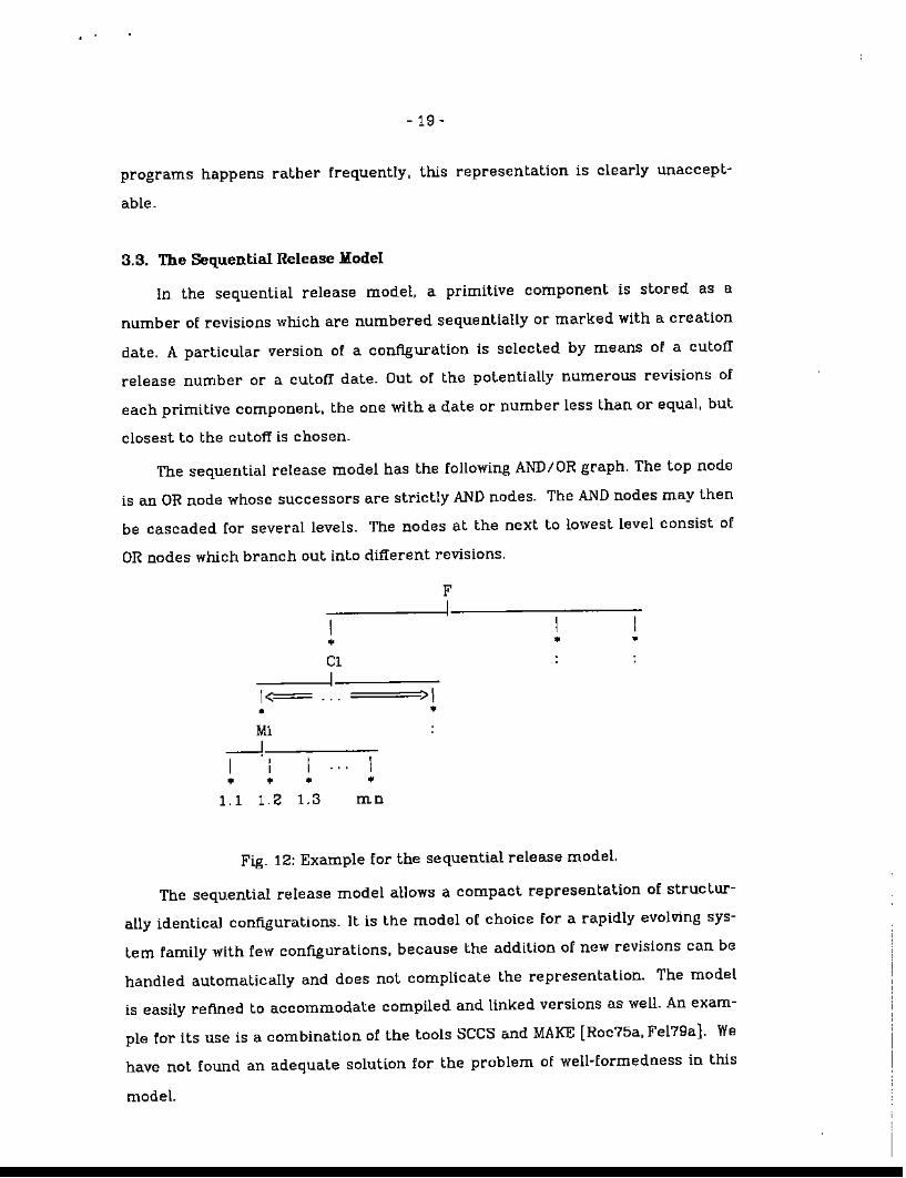
3.3. The Sequential Release Model
In the sequential release model, a primitive component is stored as e.
number of revisions which are numbered sequentially or marked with a creation
date. A particular version of a configuration is selected by means of a cutotI
release number or a cutotI dale. Out of the potentially numerous revision!:; of
each primitive component. the one with a dale or number less than or equaL but
closest to the cutoff is chosen.
The sequential release model has the following AND/OR graph. The top node
is an OR node whose successors are strictly AND nodes. The AND nodes may then
be cascaded for several levels. The nodes at the next to lowest level consist of
OR nodes which branch out into different revisions.
FI
1=•
•ClI
>1•
• •
M1
~I
,I
• • • •1.1 1.2 1.3 mn
Fig. 12: Example for the sequential release model.
The sequ.ential release model allows a compact representation of structur
ally identical configurations. It is the model of choice for a rapidly evolving sys
Lem family with few configurations, because the addition of new revisions can be
handled automatically and does not complicate the representation. The model
is easHy refined to accommodate compHed and linked versions as well. An exam
ple for its use is a combination of the tools sees and MAKE [Roc75a, FeI79a]. We
have not found an adequate solution for the problem of well-formedness in this
model.
- 20-
A disadvantage of the sequential release model is the fact that it allows no
internal OR nodes. except for revisions. Thus. all configurations that can be
derived from a single AND node are structurally identicaL Structural
differences. however slight, must be pushed all the way Lo the lop. It is therefore
not possible to indicate that two slightly ditTerent conflgurations are simUar or
vel'sions of each other. ]n addition, this causes duplication of information.
Another problem caused by the lack of internal OR nodes is that documentation
cannot he tied in conveniently.
3.'1-. The ANDIOR graph model
The representation proposed by Cooprider [Coo7Ba] allows internal OR
nodes. yel still poses a number of problems. Cooprider took a very general view
in that he did nDt distinguish between different types Df versiDns. We fDund this
view unsatisfaclDry, because it implies that the programming environment has
little or no knowledge about the kind of objects it maintains. This puts an extra
burden on the programmer in that he must repeatedly reprogram how a given
object should be handled. This can be avoided by including more type informa
tion ahoutthe objects.
Habermann [Hab60a] alld Tichy [TIc60a] allow almost complete AND/OR
graphs. except that revisions. derived versions. dDcumentation, and combina
tions of hardware and software are not treated sufficiently, and the concept of
well-formedness needs refinement. The selection problem is not addressed ade
quately. The questions Df exploiting the information in the graph for automatic
contl.guration generation. search and selection functions. and other novel
software tODls are still open.
Another example tor system families can be found in the Stoneman docu
ment [BuxBOb]. Since this paper lists only the general requirements. it is s0"!Ile
what difficult to predict a future design resulting from it. We note that internal
DR nodes are explicitly prescribed by the requirement that "configurations ...
may ... exist in version groups". HDwever, this statement in ltseU does not
require that configurations may consist of version groups rather than individual
components. Another drawback is that the requirements preclude successive
- 21 -
OR nodes (versions of versions), because version groups are not "objects". (Only
"objects" may belong to a version group.) Compare Fig, 4, 5. and 6 of Section 2
for examples where successive OR nodes are used for different types of group
ing. "Partitions" introduce an additional class of OR nodes. mostly used for top
level administrative divisions.
4. General Criteria for Programming Support Environments
In this section, we shall stale a number of properties that are desirable for
data bases on which programming support environments are buill. These pro
perUes are derived from our AND/OR graph model. As such, they are general in
that they do not depend on a particular host system or development organiza
tion. We feel that the following list is the minimum that a modern PSE data base
should provide.
J. Pull AND/OR Graph
From the disctlssion in the previous section, it is clear that a full AND/OR
graph should be permitted. In particular, we need internal OR nodes to
express version groups of configurations and primitive components, as well
as version groups of version groups. AND nodes should permit arbitrary
configurations of individual components (confIgurations and primitive com
ponents) as well as version groups. The data base should not be limited to
software, but should also store firmware. test programs, test data, docu~
mentation, and hardware descriptions. Sharing of common components
and version groups among configurations and other version groups should
he possible without duplication of information. A rich and fleXible set of
selection mechanisms should be available to choose individual versions.
n. Oustomization oJ the AND/OR Graph
If a development group decides to work with a suhmodel of the general
model. then this should be possible without complications or performance
penalties due Lo tht.: general model. For example. if a programmer develops
a single-version program using the hierarchical modeL he should not be
bothered with extra complexity or generality, Using the sequential release
- 22-
model should also result in a significant simplification.
Conversely. scaling up from a simple model to a more general one should be
possible at any time.
The AND/OR graph will take different shapes for ditIerenl organizations. for
hardware and software, for different languages and language processors. A
set of standard arrangements with certain default structures for documen
lation and test beds should be provided.
III. l:)uppression of Detail
The data base for a large system family may become extremely complex.
and there must be mechanisms to suppress unwanted detail. Certain stan
dard components like documentation and test data need not be shown
always. Derived versions like precompiled and prelinked sub-configurations
should usually be suppressed. so that the user can think and work in source
representations only. This implies that the data base must reliably handle
storage, deletion. and regeneration of derived versions.
Note that the AND/OR graph is only a model. We do not advocate AND/OR
graphs as the interface to the user. It seems that a representation in the form of
a module interconnection language as proposed in [DeR76a] is more appropri
ate. HO'l','ever, the conceptual simplicity of the AND/OR graph makes it possible
to study a large number of issues in an abstract form. such as search and syn
thesis algorithms for configurations. interface control. and the automation of
configuration management.
5. Conclusions
We developed the AND/OR graph model as a tool for abstractly describing
families of programmed systems. Tbree submodels were defined and used to
evaluate the representations underlying various software tools. The model
yielded basic requirements for the data base on which programming support
environments are built. An overview of future research was given.
- 23-
Acknowledgements. This research was supported in part by International Tele~
phone and Telegraph during the author's stay at the ITT Programming Technol
ogy Center.
References
Be179a. Belady, L.A. and Lehman. M,M., "The Characteristics of Large Systems,"pp. l06R13B in Research Directions in Software Tech:nology. ed. PelerWegner,M.LT. Press (1979).
Be177a. Belady, L.A. and Merlin, P.M., "Evolving Parts and Relations: A Model forSystem Families," Re-B6??, Technical Report, IBM Thomas J. WatsonResearch Cenler (1977).
Bir76a. Birlwistle. G., Enderin. L., Ohlin, M.. and Palme. J .. "DECsyslem-lOSimula Language Handbook Part 1," CB39B, Swedish National DerenseResearch Institute (March 1976).
BuxBOb. Buxton, John N., Requirements for Ada Programming Support Environmrmts tStonema.n"), US Department of Defense (February 1980).
Bux80a. Buxton, John N. and Druffel, Larry E., "ReqUirements for an Ada Programming Support Environment: Rationale for Stoneman," pp. 66-72 inProceedings of COMPSAC 80. IEEE Computer Society Press (Oct. 1980).
Che79a. Cheriton, David R.. Malcom, Michael A.. Melen, Lawrence S .. and Sager.Garry R, "Thoth. a Portable Real-Time Operating System," Communica~
tions of the ACM 22(2) pp. 105-115 (Feb. 1979).Cle75a. Cleveland. J.e .. The Environ and Using Facilities of Algol B8C, Computer
Science Department. UCLA (April 1975). Modeling and Measuring Note, No.SS.
Coo78a. Cooprider. Lee W., The Representation of Families of Programmed Systems, PhD thesis, Carnegie-Mellon University. Department of Computer Science (1978).
DeR76a. DeRemer, Frank and Kron, Hans H., "Programming-in-the-Large vs.Programming-in~the-Small." IEEE Transactions on Softwa:re EngineeringSE-,2(2) pp. 60-66 (June 1976).
DoD77a. DoD.. "Department of Defense Requirements for Higher Order Computer Programming Languages. Revised lronman." SIGPLAN Notices12(12)(Dec.1977).
Els7~a. Elson. Mark. Concepts of Progra.mming Languages, Science ResearchAssociates, Inc. (1973).
F'eI79a. Feldman, Stuart 1.. "Make - A Program for Maintaining Computer Programs," Software - Practice and Experienr.;e 9(3) pp. 255-265 (March 1979).
Hab79a. Habermann, A. Nico. "An Overview Ol the GandaIf Project," in CMU Computer Science Research Review 1978-19'19, Carnegle-Mellon University(1979).
Hab7Ga. Habermann, A. Nico, Flon, Lo.wrence. and Cooprider, Lee W.. "ModularizaUon and Hierarchy in a Family of Operating System:::;," Communicationsof the ACM 19(5) pp. 266-272 (May 1976).
,
- 24-
HabBOa. Habermann. A. Nico and Perry. De\\<ayne E.. "Well-Formed System Compositions," CMU-CS-BO-117, Technical Report, Carnegie-Mellon University,Department of Computer Science (March 1980).
I'ITBOa. 1'IT" CMSS3 UseT~"s Manual. International Telephone and Telegraph(1980). Document No. 211l'IT26366-PC
lehBOa. lchbiah, Jean D., Reference Man1Lal for the Ada Progra.mming La.nguage,United States Department of Defense (July 19BO).
Ker79a. Kernighan, Brian W. and Mashey, John R.. "The UNIX ProgrammingEnvironment," Software - Practice and Experience 9(1) pp. 1-15 (Jan.1979).
Ker78a. Kernighan, Brian W. and Ritchie. Dennis M., The C ProgTammingLang1J,age, Prentice-Hall (1978).
LavBDa. Love, Tom. Canfigwration Control for Telecommunications Systems,personal 'communication, 19BO.
Mit78a. Mitchell, James G., Maybury, William, and Sweet, Rlchard, MesaLanguage Ma:nuaL, Technical Report, Xerox Palo Alto Research Center (Feb.1976).
Nil71a. Nilsson, Nils J., Probtem SoLving Methods in Art1Ji.ciaL IntelLigence,McGraw-Hill (1971).
Not79a. Notkin, David S. and Habermann, A. Nico, SDC Documentation,Carnegie-Mellon University, Department of Computer Science (1979).
Par76a. Par-nas, David L., "On the Design and Development of Program Families," IEEE Transactions on Software FJngineering SE-B(l) pp. 1-8 (Mar.1976).
Par79a. ParnfJ.s, David L., "Designing Software for Ease of Extension and ConLraction," IEEE 1'ransadions on Software E'ngineering SE-5(Z) pp. 128~138
(March 1979),RidBOa. Rtddle, William E., "Panel: Software Development Environments," pp.
220-224 In Proceedings of COMPSAC 80, IEEE Computer Society Press (Oct.1900).
Rig69a. Rigney, Joseph W. and Towne, Dougals M., "Computer Techlliques forAnalyzing the Microstructure of Serial-Action Work in Industry," HumanF'acloTs 11(2) pp. 1l3-121 (AprllI969).
Roc7fia. Rochkind, Marc J., "The Source Code Control System," IEEE Transactions: on Software Engineering SE-l(4) pp. 364-370 (Dec. 1975).
Tic79a. Tichy, Walter F., "Software Development Control Based on Module Inter~
connection," pp. 29~41 in Proceedings of the 4th International Conferenceon Software Engineering, ACM, IEEE, ERO. GI (Sept. 1979).
Tic BOa. Tichy, Walter F., Softwa.re Development Control Based on System Structure Description, PhD Thesis, Carnegie-Mellon University, Department ofComputer Science (Jan. 1980).
'l'icBOb. Tichy, Walter F., Configuration ControL Tools 1.71. the 1980's, TechnicalReport, ITT Programming Technology Center (1980).
Wir71a. Wirth, Niklaus, "The Programming Language PascaL" Acta Informatica1 pp. 35-63 (1971).
, ,