Embed Size (px)
Citation preview
Hydrol. Earth Syst. Sci., 12, 55–74, 2008www.hydrol-earth-syst-sci.net/12/55/2008/© Author(s) 2008. This work is licensedunder a Creative Commons License.
Hydrology andEarth System
Sciences
A model for hydraulic redistribution incorporating coupled soil-rootmoisture transport
G. G. Amenu and P. Kumar
Department of Civil and Environmental Engineering, University of Illinois, Urbana, IL 61801, USA
Received: 17 September 2007 – Published in Hydrol. Earth Syst. Sci. Discuss.: 4 October 2007Revised: 7 December 2007 – Accepted: 10 December 2007 – Published: 24 January 2008
Abstract. One of the adaptive strategies of vegetation, par-ticularly in water limited ecosystems, is the developmentof deep roots and the use of hydraulic redistribution whichenables them to make optimal use of resources availablethroughout the soil column. Hydraulic redistribution refersto roots acting as a preferential pathway for the movementof water from wet to dry soil layers driven by the mois-ture gradient – be it from the shallow to deep layers or viceversa. This occurs during the nighttime while during the day-time moisture movement is driven to fulfill the transpirationdemand at the canopy. In this study, we develop a modelto investigate the effect of hydraulic redistribution by deeproots on the terrestrial climatology. Sierra Nevada eco-regionis chosen as the study site which has wet winters and drysummers. Hydraulic redistribution enables the movement ofmoisture from the upper soil layers to deeper zones duringthe wet months and this moisture is then available to meetthe transpiration demand during the late dry season. It resultsin significant alteration of the profiles of soil moisture andwater uptake as well as increase in the canopy transpiration,carbon assimilation, and the associated water-use-efficiencyduring the dry summer season. This also makes the pres-ence of roots in deeper soil layers much more important thantheir proportional abundance would otherwise dictate. Com-parison with observations of latent heat from a flux towerdemonstrates improved predictability and provides valida-tion of the model results. Hydraulic redistribution servesas a mechanism for the interaction between the variabilityof deep layer soil-moisture and the land-surface climatologyand could have significant implications for seasonal and sub-seasonal climate prediction.
Correspondence to:P. Kumar([email protected])
1 Introduction
Plants are known to exhibit an evolutionary adaptation to ad-verse environmental pressures. This includes unique growthforms that increase competitiveness for light and water. Byshifting the balances of environmental stresses in favor ofthe plant, the adaptation increases the plant’s chances of sur-vival and productivity. One of such unique adaptations thathas received increasing attention over the last two decadesis the deep-rooting nature of plants (Stone and Kalisz, 1991;Canadell et al., 1996; Jackson et al., 1999) and the associatedphenomenon known as “hydraulic lift” (Richards and Cald-well, 1987; Caldwell and Richards, 1989; Dawson, 1993,1996; Caldwell et al, 1998), or recently termed as “hydraulicredistribution” (Burgess et al., 1998, 2000, 2001; Hultine etal., 2003, 2004; Brooks et al., 2002, 2006). Root systems ofplants are known to extend vertically into the soil for con-siderable depths and tap water and nutrients from both deepand shallow soil layers, that is, they exhibit patterns of up-take of water and nutrients in accordance with the variabilityof resources at different soil depths.
The term “hydraulic lift” (hereinafter, HL) refers to thepassive movement of water via plant roots from deep moistersoil layers to shallow drier soil layers. The term hydraulicredistribution (hereinafter, HR) is a general term that incor-porates both the upward, and the downward transfer of water,i.e. from shallower layers to deeper layers via roots (inverseHL) (Schulze et al., 1998; Smith et al., 1999). Thus, HRcan be defined as “a passive movement of water via plantroots from relatively moist soil layers to drier soil layers”. InHR, plant roots form a conveyance system between soil lay-ers through which water is transported.Therefore, moisturegets absorbed and released in response to gradients in waterpotential between the roots and the soil. This is in agreementwith the theory for water movement in soil-plant-atmospherecontinuum (SPAC), in which water transport is governed bywater potential gradient (Dixon, 1914; van den Honert, 1948;Philip, 1966; Kramer and Boyer, 1995).
Published by Copernicus Publications on behalf of the European Geosciences Union.
56 G. G. Amenu and P. Kumar: A model for hydraulic redistribution
48
Day Night
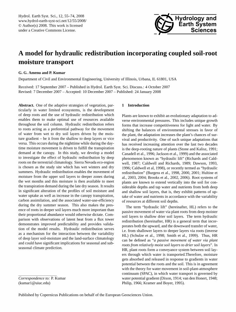
Figure 1: Schematic description of the hydraulic redistribution. Fig. 1. Schematic description of the hydraulic redistribution.
Figure 1 shows a schematic of the hydraulic redistribu-tion. During transpiration from the leaves, the open stom-ata creates water potential gradient between the leaves andthe roots, resulting in net water movement from the soil tothe roots and then to the leaves. Water is absorbed from alldepths depending upon the potential gradient and passes intothe transpiration stream at the leaves. This is true both dur-ing wet and dry seasons. When the stomata close, it results inturgor pressure that increases water potential within the plantbody. As the potential in the root exceeds the potential in thedrier part of the soil, moisture starts to efflux from the root tothe dry soil, while water still continues to flow into the rootsin the wetter part of the soil. During dry seasons, the uppersoil is often drier than the deeper part of the soil, and the netwater transport via the roots during night is thus upwards,from deeper to shallower layers, as shown in the left-panelof Fig. 1. On the other hand, during wet seasons, the uppersoil layers get wetter than the deeper layers, and the net watermovement through the roots will be downwards as shown inthe right-panel of Fig. 1.
Hydraulic redistribution is a reverse flow, in the sense, thatthe moisture transport occurs in the reverse direction, fromthe root to the soil, than what transpiration dictates. The ori-gin and evolution of this phenomenon is not clear yet, butthere is much experimental evidence that shows its existencein numerous plant species (Table 1). This evidence, comingfrom both laboratory and field experimental studies, showsthat this process moves water through the soil profile at amuch faster rate than could have been possible by gravityand diffusion in the soil matrix alone.
Though the majority of the documented cases of HR arefor arid and semi-arid environments, given the phenomenonis dictated by water potential gradients, it undoubtedly isa feature in any vegetated environment experiencing water-limitation in parts of the root system (Oliveira et al. 2005).If root systems span a suitable water potential gradient,HR should be expected as long as there is no impedimentto the reverse flow, that is, the efflux of water from theroots, and considerable evidence supports this hypothesis.
49
Flow in the root xylem
Soil Root
Flow in the soil pores
Flow into the root from the
soil
Hydraulic Redistribution
Infiltration Transpiration
Bottom Drainage
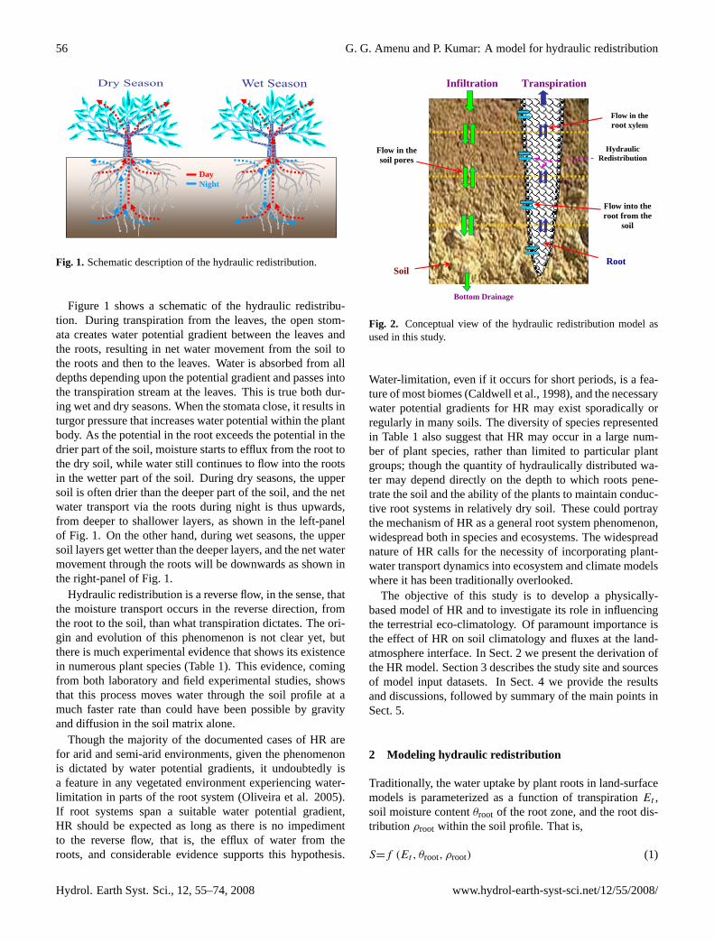
Figure 2: Conceptual view of the hydraulic redistribution model as used in this study. Fig. 2. Conceptual view of the hydraulic redistribution model asused in this study.
Water-limitation, even if it occurs for short periods, is a fea-ture of most biomes (Caldwell et al., 1998), and the necessarywater potential gradients for HR may exist sporadically orregularly in many soils. The diversity of species representedin Table 1 also suggest that HR may occur in a large num-ber of plant species, rather than limited to particular plantgroups; though the quantity of hydraulically distributed wa-ter may depend directly on the depth to which roots pene-trate the soil and the ability of the plants to maintain conduc-tive root systems in relatively dry soil. These could portraythe mechanism of HR as a general root system phenomenon,widespread both in species and ecosystems. The widespreadnature of HR calls for the necessity of incorporating plant-water transport dynamics into ecosystem and climate modelswhere it has been traditionally overlooked.
The objective of this study is to develop a physically-based model of HR and to investigate its role in influencingthe terrestrial eco-climatology. Of paramount importance isthe effect of HR on soil climatology and fluxes at the land-atmosphere interface. In Sect. 2 we present the derivation ofthe HR model. Section 3 describes the study site and sourcesof model input datasets. In Sect. 4 we provide the resultsand discussions, followed by summary of the main points inSect. 5.
2 Modeling hydraulic redistribution
Traditionally, the water uptake by plant roots in land-surfacemodels is parameterized as a function of transpirationEt ,soil moisture contentθroot of the root zone, and the root dis-tributionρroot within the soil profile. That is,
S=f (Et , θroot, ρroot) (1)
Hydrol. Earth Syst. Sci., 12, 55–74, 2008 www.hydrol-earth-syst-sci.net/12/55/2008/
G. G. Amenu and P. Kumar: A model for hydraulic redistribution 57
Table 1. Some laboratory and field evidences of hydraulic redistribution by plant roots.
Source Plant Species Study Site
Mooney et al. (1980) Shrubs Atacama Desert, Chilevan Bavel & Baker (1985) Bermudagrass Lab ExperimentCorak et al. (1987) Alfalfa Lab ExperimentRichards & Caldwell (1987) Sagebrush, Grass Utah, USABaker & van Bavel (1988) Cotton Lab ExperimentCaldwell & Richards (1989) Sagebrush, Grass Utah, USADawson (1993) Sugar Maples New York, USAWan et al. (1993) Broom Snakeweed Texas, USADawson & Pate (1996) Proteaceous trees Western AustraliaEmerman & Dawson (1996) Sugar Maples New York, USABurgess et al. (1998) Silky Oak Kenya, AfricaBurgess et al. (1998) Eucalyptus tree Western AustraliaYoder & Nowak (1999) Shrubs, Grasses Mojave Desert, Nevada, USABurgess et al. (2000) Proteaceous tree Western AustraliaMillikin & Bledsoe (2000) Blue Oaks California, USASong et al. (2000) Sunflower Lab Experiment, KansasWan et al. (2000) Maize Lab ExperimentBrooks et al. (2002) Ponderosa pine Oregon, USABrooks et al. (2002) Douglas-fir Washington, USALudwig et al. (2003) Savanna trees Tanzania, AfricaMoreira et al. (2003) Savanna Central BrazilEspeleta et al. (2004) Oaks, bunch grass South Carolina, USAHultine et al. (2004) Leguminous tree Arizona, USALeffler et al. (2005) Cheatgrass Rush Valley, Utah, USAOliveira et al. (2005) Amazon trees BrazilBrooks et al. (2006) Douglas-fir Washington, USA
whereS is the water extracted by roots, and it is incorpo-rated as a sink term in the Richards equation for vegetatedenvironments, given as
∂θ
∂t=∂
∂z
[Ksh
(∂ψsm
∂z− 1
)]− S (2)
whereθ(z) is the volumetric soil moisture content,t is time,Ksh(z) is soil hydraulic conductivity,ψsm(z) is soil matricpotential, andz is depth. For notational convenience, explicitdependence of the variables onz is dropped, henceforth.There are several variants of Eq. (1), as can be seen fromthe formulations in current land surface models (e.g. Lianget al., 1994; Wetzel and Boone, 1995; Dai et al., 2003; Ole-son et al., 2004). However, they do not incorporate the flowdynamics within the root system, and hence, the importanceof moisture redistribution via plant roots.
Modeling the effect of moisture redistribution by plantroots demands the consideration of flow in the root systemin conjunction with flow in the soil. In such a modeling ap-proach, plant roots can be viewed as a continuum like thesoil media. While it may not be practical to model flow inindividual roots, macroscopic approaches that consider theroot system as a whole, that is, a “big root” model, might beconsidered for such purposes. In the past, very few attempts
have been made to model HR (e.g. Ryel et al., 2002; Ren etal., 2004; Lee et al., 2005). These models, however, param-eterize the hydraulic redistribution as a function of the wa-ter potential between different soil layers and do not modelthe actual pathway for moisture movement within the plantsystem. The present work is distinct in that we have devel-oped a physically-based dynamic model of HR that includestwo way moisture movements through the coupled soil-roottransport system.
Our approach of modeling HR couples water flows withinthe soil and root media, where flow in both media is gov-erned by the water potential gradient and the hydraulic con-ductivities of the systems. The root is assumed to absorbmoisture from and/or release moisture to the soil, dependingon the water potential gradient. In doing so, the root systemis considered as a conduit for moisture transport from wetsoil reservoirs to dry soil reservoirs, while at the same timeconveying moisture to fulfill the transpiration demand at thecanopy. Governing equations for flow through both soil androot are solved as a set of coupled equations. Figure 2 showsa schematic description of the model. A detailed derivationof the root model, as developed in this study, is presentednext.
www.hydrol-earth-syst-sci.net/12/55/2008/ Hydrol. Earth Syst. Sci., 12, 55–74, 2008
58 G. G. Amenu and P. Kumar: A model for hydraulic redistribution
50
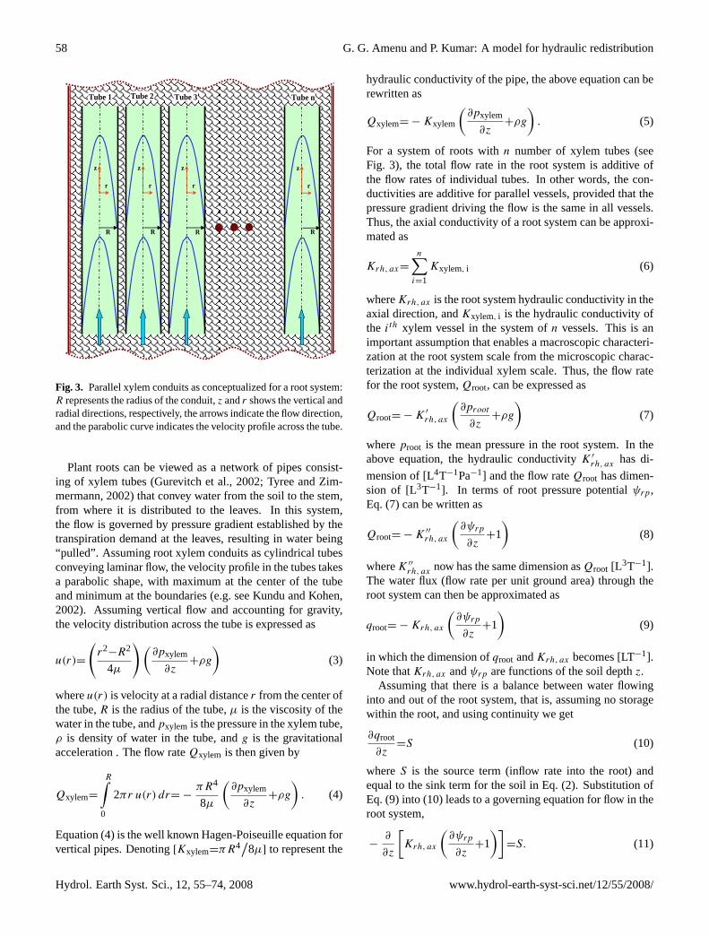
Figure 3: Parallel xylem conduits as conceptualized for a root system: R represents the radius of the conduit, z and r shows the vertical and radial directions, respectively, the arrows indicate the flow direction, and the parabolic curve indicates the velocity profile across the tube.
r
z
R
r
z
R
r
z
R
r
z
R
Tube 1 Tube 2 Tube 3 Tube n
Fig. 3. Parallel xylem conduits as conceptualized for a root system:R represents the radius of the conduit,z andr shows the vertical andradial directions, respectively, the arrows indicate the flow direction,and the parabolic curve indicates the velocity profile across the tube.
Plant roots can be viewed as a network of pipes consist-ing of xylem tubes (Gurevitch et al., 2002; Tyree and Zim-mermann, 2002) that convey water from the soil to the stem,from where it is distributed to the leaves. In this system,the flow is governed by pressure gradient established by thetranspiration demand at the leaves, resulting in water being“pulled”. Assuming root xylem conduits as cylindrical tubesconveying laminar flow, the velocity profile in the tubes takesa parabolic shape, with maximum at the center of the tubeand minimum at the boundaries (e.g. see Kundu and Kohen,2002). Assuming vertical flow and accounting for gravity,the velocity distribution across the tube is expressed as
u(r)=
(r2
−R2
4µ
)(∂pxylem
∂z+ρg
)(3)
whereu(r) is velocity at a radial distancer from the center ofthe tube,R is the radius of the tube,µ is the viscosity of thewater in the tube, andpxylem is the pressure in the xylem tube,ρ is density of water in the tube, andg is the gravitationalacceleration . The flow rateQxylem is then given by
Qxylem=
R∫0
2πr u(r) dr= −πR4
8µ
(∂pxylem
∂z+ρg
). (4)
Equation (4) is the well known Hagen-Poiseuille equation forvertical pipes. Denoting[Kxylem=πR4
/8µ] to represent the
hydraulic conductivity of the pipe, the above equation can berewritten as
Qxylem= −Kxylem
(∂pxylem
∂z+ρg
). (5)
For a system of roots withn number of xylem tubes (seeFig. 3), the total flow rate in the root system is additive ofthe flow rates of individual tubes. In other words, the con-ductivities are additive for parallel vessels, provided that thepressure gradient driving the flow is the same in all vessels.Thus, the axial conductivity of a root system can be approxi-mated as
Krh, ax=
n∑i=1
Kxylem, i (6)
whereKrh, ax is the root system hydraulic conductivity in theaxial direction, andKxylem, i is the hydraulic conductivity ofthe ith xylem vessel in the system ofn vessels. This is animportant assumption that enables a macroscopic characteri-zation at the root system scale from the microscopic charac-terization at the individual xylem scale. Thus, the flow ratefor the root system,Qroot, can be expressed as
Qroot= −K ′
rh, ax
(∂proot
∂z+ρg
)(7)
whereproot is the mean pressure in the root system. In theabove equation, the hydraulic conductivityK ′
rh, ax has di-
mension of [L4T−1Pa−1] and the flow rateQroot has dimen-sion of [L3T−1]. In terms of root pressure potentialψrp,Eq. (7) can be written as
Qroot= −K ′′
rh, ax
(∂ψrp
∂z+1
)(8)
whereK ′′
rh, ax now has the same dimension asQroot [L3T−1].The water flux (flow rate per unit ground area) through theroot system can then be approximated as
qroot= −Krh, ax
(∂ψrp
∂z+1
)(9)
in which the dimension ofqroot andKrh, ax becomes [LT−1].Note thatKrh, ax andψrp are functions of the soil depthz.
Assuming that there is a balance between water flowinginto and out of the root system, that is, assuming no storagewithin the root, and using continuity we get
∂qroot
∂z=S (10)
whereS is the source term (inflow rate into the root) andequal to the sink term for the soil in Eq. (2). Substitution ofEq. (9) into (10) leads to a governing equation for flow in theroot system,
−∂
∂z
[Krh, ax
(∂ψrp
∂z+1
)]=S. (11)
Hydrol. Earth Syst. Sci., 12, 55–74, 2008 www.hydrol-earth-syst-sci.net/12/55/2008/
G. G. Amenu and P. Kumar: A model for hydraulic redistribution 59
51
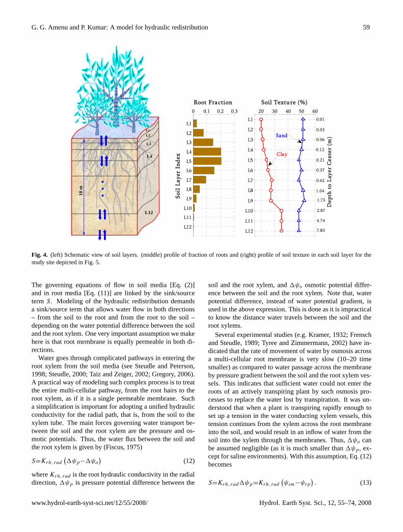
Figure 4: (left) Schematic view of soil layers. (Middle) profile of fraction of roots and (right) profile of soil texture in each soil layer for the study site depicted in figure 5.
• • •
L4
L1 L2
L3
L12
10 m
0 0.1 0.2 0.3
L1
L2
L3
L4
L5
L6
L7
L8
L9
L10
L11
L12
Root Fraction
Soil
Lay
er I
ndex
Dep
th t
o La
yer
Cen
ter
(m)
20 30 40 50 60
L1
L2
L3
L4
L5
L6
L7
L8
L9
L10
L11
L12
Soil Texture (%)
Clay
Sand
0.01
1.73
0.06
0.03
1.04
0.62
0.37
0.21
0.12
7.83
4.74
2.87
Fig. 4. (left) Schematic view of soil layers. (middle) profile of fraction of roots and (right) profile of soil texture in each soil layer for thestudy site depicted in Fig. 5.
The governing equations of flow in soil media [Eq. (2)]and in root media [Eq. (11)] are linked by the sink/sourceterm S. Modeling of the hydraulic redistribution demandsa sink/source term that allows water flow in both directions– from the soil to the root and from the root to the soil –depending on the water potential difference between the soiland the root xylem. One very important assumption we makehere is that root membrane is equally permeable in both di-rections.
Water goes through complicated pathways in entering theroot xylem from the soil media (see Steudle and Peterson,1998; Steudle, 2000; Taiz and Zeiger, 2002; Gregory, 2006).A practical way of modeling such complex process is to treatthe entire multi-cellular pathway, from the root hairs to theroot xylem, as if it is a single permeable membrane. Sucha simplification is important for adopting a unified hydraulicconductivity for the radial path, that is, from the soil to thexylem tube. The main forces governing water transport be-tween the soil and the root xylem are the pressure and os-motic potentials. Thus, the water flux between the soil andthe root xylem is given by (Fiscus, 1975)
S=Krh, rad(1ψp−1ψo
)(12)
whereKrh, rad is the root hydraulic conductivity in the radialdirection,1ψp is pressure potential difference between the
soil and the root xylem, and1ψo osmotic potential differ-ence between the soil and the root xylem. Note that, waterpotential difference, instead of water potential gradient, isused in the above expression. This is done as it is impracticalto know the distance water travels between the soil and theroot xylems.
Several experimental studies (e.g. Kramer, 1932; Frenschand Steudle, 1989; Tyree and Zimmermann, 2002) have in-dicated that the rate of movement of water by osmosis acrossa multi-cellular root membrane is very slow (10–20 timesmaller) as compared to water passage across the membraneby pressure gradient between the soil and the root xylem ves-sels. This indicates that sufficient water could not enter theroots of an actively transpiring plant by such osmosis pro-cesses to replace the water lost by transpiration. It was un-derstood that when a plant is transpiring rapidly enough toset up a tension in the water conducting xylem vessels, thistension continues from the xylem across the root membraneinto the soil, and would result in an inflow of water from thesoil into the xylem through the membranes. Thus,1ψo canbe assumed negligible (as it is much smaller than1ψp, ex-cept for saline environments). With this assumption, Eq. (12)becomes
S=Krh, rad1ψp=Krh, rad(ψsm−ψrp
). (13)
www.hydrol-earth-syst-sci.net/12/55/2008/ Hydrol. Earth Syst. Sci., 12, 55–74, 2008
60 G. G. Amenu and P. Kumar: A model for hydraulic redistribution
52
Fresno
Sierra Nevada
Study Site
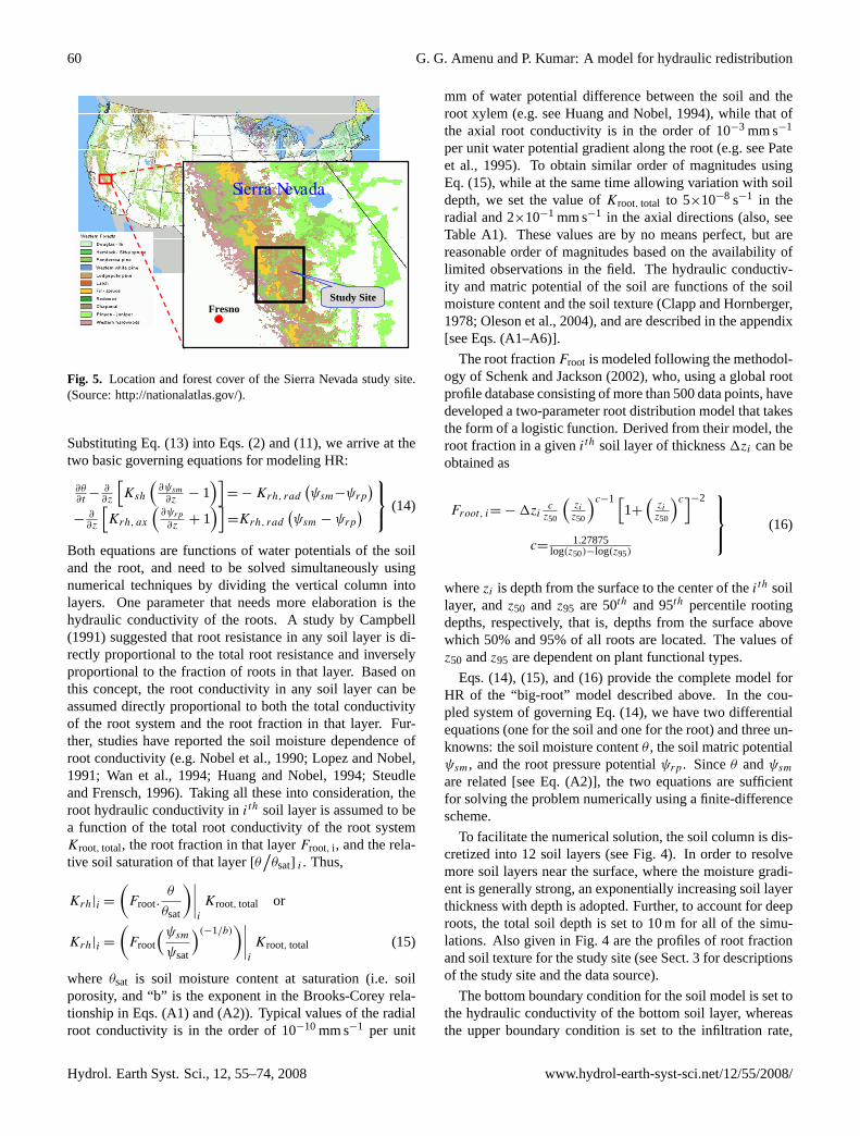
Figure 5: Location and forest cover of the Sierra Nevada study site. (Source: http://nationalatlas.gov/) Fig. 5. Location and forest cover of the Sierra Nevada study site.(Source:http://nationalatlas.gov/).
Substituting Eq. (13) into Eqs. (2) and (11), we arrive at thetwo basic governing equations for modeling HR:
∂θ∂t
−∂∂z
[Ksh
(∂ψsm∂z
− 1)]
= −Krh, rad(ψsm−ψrp
)−
∂∂z
[Krh, ax
(∂ψrp∂z
+ 1)]
=Krh, rad(ψsm − ψrp
) (14)
Both equations are functions of water potentials of the soiland the root, and need to be solved simultaneously usingnumerical techniques by dividing the vertical column intolayers. One parameter that needs more elaboration is thehydraulic conductivity of the roots. A study by Campbell(1991) suggested that root resistance in any soil layer is di-rectly proportional to the total root resistance and inverselyproportional to the fraction of roots in that layer. Based onthis concept, the root conductivity in any soil layer can beassumed directly proportional to both the total conductivityof the root system and the root fraction in that layer. Fur-ther, studies have reported the soil moisture dependence ofroot conductivity (e.g. Nobel et al., 1990; Lopez and Nobel,1991; Wan et al., 1994; Huang and Nobel, 1994; Steudleand Frensch, 1996). Taking all these into consideration, theroot hydraulic conductivity inith soil layer is assumed to bea function of the total root conductivity of the root systemKroot, total, the root fraction in that layerFroot, i , and the rela-tive soil saturation of that layer[θ
/θsat] i . Thus,
Krh|i =
(Froot.
θ
θsat
)∣∣∣∣i
Kroot, total or
Krh|i =
(Froot
(ψsmψsat
)(−1/b))∣∣∣∣i
Kroot, total (15)
where θsat is soil moisture content at saturation (i.e. soilporosity, and “b” is the exponent in the Brooks-Corey rela-tionship in Eqs. (A1) and (A2)). Typical values of the radialroot conductivity is in the order of 10−10 mm s−1 per unit
mm of water potential difference between the soil and theroot xylem (e.g. see Huang and Nobel, 1994), while that ofthe axial root conductivity is in the order of 10−3 mm s−1
per unit water potential gradient along the root (e.g. see Pateet al., 1995). To obtain similar order of magnitudes usingEq. (15), while at the same time allowing variation with soildepth, we set the value ofKroot, total to 5×10⁻⁸ s−1 in theradial and 2×10⁻¹ mm s−1 in the axial directions (also, seeTable A1). These values are by no means perfect, but arereasonable order of magnitudes based on the availability oflimited observations in the field. The hydraulic conductiv-ity and matric potential of the soil are functions of the soilmoisture content and the soil texture (Clapp and Hornberger,1978; Oleson et al., 2004), and are described in the appendix[see Eqs. (A1–A6)].
The root fractionFroot is modeled following the methodol-ogy of Schenk and Jackson (2002), who, using a global rootprofile database consisting of more than 500 data points, havedeveloped a two-parameter root distribution model that takesthe form of a logistic function. Derived from their model, theroot fraction in a givenith soil layer of thickness1zi can beobtained as
Froot, i= −1zicz50
(ziz50
)c−1 [1+
(ziz50
)c]−2
c= 1.27875log(z50)−log(z95)
(16)
wherezi is depth from the surface to the center of theith soillayer, andz50 andz95 are 50th and 95th percentile rootingdepths, respectively, that is, depths from the surface abovewhich 50% and 95% of all roots are located. The values ofz50 andz95 are dependent on plant functional types.
Eqs. (14), (15), and (16) provide the complete model forHR of the “big-root” model described above. In the cou-pled system of governing Eq. (14), we have two differentialequations (one for the soil and one for the root) and three un-knowns: the soil moisture contentθ , the soil matric potentialψsm, and the root pressure potentialψrp. Sinceθ andψsmare related [see Eq. (A2)], the two equations are sufficientfor solving the problem numerically using a finite-differencescheme.
To facilitate the numerical solution, the soil column is dis-cretized into 12 soil layers (see Fig. 4). In order to resolvemore soil layers near the surface, where the moisture gradi-ent is generally strong, an exponentially increasing soil layerthickness with depth is adopted. Further, to account for deeproots, the total soil depth is set to 10 m for all of the simu-lations. Also given in Fig. 4 are the profiles of root fractionand soil texture for the study site (see Sect. 3 for descriptionsof the study site and the data source).
The bottom boundary condition for the soil model is set tothe hydraulic conductivity of the bottom soil layer, whereasthe upper boundary condition is set to the infiltration rate,
Hydrol. Earth Syst. Sci., 12, 55–74, 2008 www.hydrol-earth-syst-sci.net/12/55/2008/
G. G. Amenu and P. Kumar: A model for hydraulic redistribution 61
which is modeled as the minimum of throughfall and avail-able capacity in the top soil layer, that is,
qinf l= min(qthrough,
1z11t(θsat,1−θ1)
)qthrough=qraine
−ζ×LAI
}(17)
whereqthrough is throughfall,qrain is gross precipitation rate,andζ is a constant,LAI is leaf area index,1z1 is the thick-ness of top soil layer,θ1 is moisture content of the top soillayer, θsat,1 is the moisture content at saturation of the topsoil layer, and1t is the model time step. The equation forthroughfall assumes that the amount of rain intercepted bythe canopy is a function of theLAI , specifically of the formdq/dL=−constantq, whereL is theLAI . The second partof Eq. (17) results from the integration from the top of thecanopy (q=qrain) to the ground (q=qthrough). The first partof equation says that the infiltration will not exceed the avail-able capacity of the first soil-layer to take in the water for acomputational time step ofδt units. The bottom boundarycondition for the root model is set to no flux boundary con-dition, and the upper boundary condition is set to the tran-spiration rate. The “big-leaf” approach of Penman-Monteith(Monteith and Unsworth, 1990) is used to model the transpi-ration from the canopy and is described in the Appendix.
The model presented above makes some important as-sumptions such as
– It assumes that the entire root system is absorbing andthis does not change with time.
– It ignores the flow resistance offered by the end wall pit-pore membranes that connect xylem conduits (Hacke etal, 2006).
– It does not incorporate temperature induced changes inwater viscosity and root hydraulic properties.
– It does not incorporate limitations in HR due to thechanges in nighttime stomatal conductances.
These assumptions may be relaxed through future work andwhen data becomes available to enable better parameteriza-tion across different plant functional types.
3 Study site and model input data
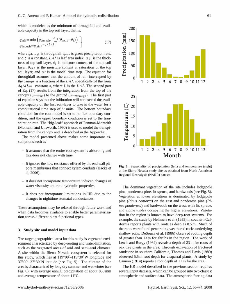
The target geographical area for this study is vegetated envi-ronment characterized by deep-rooting and water-limitation,such as the vegetated areas of arid and semi-arid climates.A site within the Sierra Nevada ecosystem is selected forthis study, which lies at 119◦00′–119◦30′ W longitude and37◦00′–37◦30′ N latitude (see Fig. 5). The climate of thearea is characterized by long dry summer and wet winter (seeFig. 6), with average annual precipitation of about 850 mmand average temperature of about 11◦C.
53
Figure 6: Seasonality of precipitation (left) and temperature (right) at the Sierra Nevada study site as obtained from North American Regional Reanalysis (NARR) dataset.
1 2 3 4 5 6 7 8 9 10 11 120
50
100
150
200
Pre
cipi
tati
on (
mm
)
1 2 3 4 5 6 7 8 9 10 11 120
5
10
15
20
25
Tem
pera
ture
(C
)
Month
Fig. 6. Seasonality of precipitation (left) and temperature (right)at the Sierra Nevada study site as obtained from North AmericanRegional Reanalysis (NARR) dataset.
The dominant vegetation of the site includes lodgepolepine, ponderosa pine, fir-spruce, and hardwoods (see Fig. 5).Vegetation at lower elevations is dominated by lodgepolepine (Pinus contorta) on the east and ponderosa pine (Pi-nus ponderosa) and hardwoods on the west, with fir, spruce,and alpine tundra occupying the higher elevations. Vegeta-tion in the region is known to have deep-root systems. Forexample, the study by Hellmers et al. (1955) in southern Cal-ifornia reports plants with roots as deep as 8.5 m. Much ofthe roots were found penetrating weathered rocks underlyingshallow soils. DeSouza et al. (1986) observed rooting depthof greater than 13 m for shrubs in the region. The work ofLewis and Burgy (1964) reveals a depth of 23 m for roots ofoak tree plants in the area. Through excavation of fracturedsandstone in southern California, Thomas and Davis (1989)observed 5.5 m root depth for chaparral plants. A study byCannon (1914) reports a root depth of 11 m for the area.
The HR model described in the previous section requiresseveral input datasets, which can be grouped into two classes:atmospheric and surface data. The atmospheric forcing data
www.hydrol-earth-syst-sci.net/12/55/2008/ Hydrol. Earth Syst. Sci., 12, 55–74, 2008
62 G. G. Amenu and P. Kumar: A model for hydraulic redistribution
54
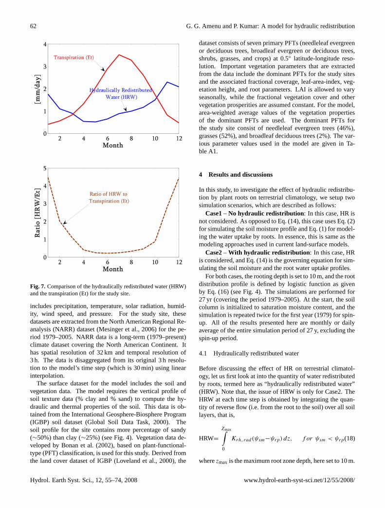
Figure 7: Comparison of the hydraulically redistributed water (HRW) and the transpiration (Et) for the study site.
2 4 6 8 10 120
1
2
3
4
Month
[mm
/day
]
2 4 6 8 10 120
1
2
3
4
5
Month
Rat
io [
HR
W/E
t]
Hydraulically Redistributed Water (HRW)
Transpiration (Et)
Ratio of HRW to Transpiration (Et)
Fig. 7. Comparison of the hydraulically redistributed water (HRW)and the transpiration (Et) for the study site.
includes precipitation, temperature, solar radiation, humid-ity, wind speed, and pressure. For the study site, thesedatasets are extracted from the North American Regional Re-analysis (NARR) dataset (Mesinger et al., 2006) for the pe-riod 1979–2005. NARR data is a long-term (1979–present)climate dataset covering the North American Continent. Ithas spatial resolution of 32 km and temporal resolution of3 h. The data is disaggregated from its original 3 h resolu-tion to the model’s time step (which is 30 min) using linearinterpolation.
The surface dataset for the model includes the soil andvegetation data. The model requires the vertical profile ofsoil texture data (% clay and % sand) to compute the hy-draulic and thermal properties of the soil. This data is ob-tained from the International Geosphere-Biosphere Program(IGBP) soil dataset (Global Soil Data Task, 2000). Thesoil profile for the site contains more percentage of sandy(∼50%) than clay (∼25%) (see Fig. 4). Vegetation data de-veloped by Bonan et al. (2002), based on plant-functional-type (PFT) classification, is used for this study. Derived fromthe land cover dataset of IGBP (Loveland et al., 2000), the
dataset consists of seven primary PFTs (needleleaf evergreenor deciduous trees, broadleaf evergreen or deciduous trees,shrubs, grasses, and crops) at 0.5◦ latitude-longitude reso-lution. Important vegetation parameters that are extractedfrom the data include the dominant PFTs for the study sitesand the associated fractional coverage, leaf-area-index, veg-etation height, and root parameters. LAI is allowed to varyseasonally, while the fractional vegetation cover and othervegetation prosperities are assumed constant. For the model,area-weighted average values of the vegetation propertiesof the dominant PFTs are used. The dominant PFTs forthe study site consist of needleleaf evergreen trees (46%),grasses (52%), and broadleaf deciduous trees (2%). The var-ious parameter values used in the model are given in Ta-ble A1.
4 Results and discussions
In this study, to investigate the effect of hydraulic redistribu-tion by plant roots on terrestrial climatology, we setup twosimulation scenarios, which are described as follows:
Case1– No hydraulic redistribution : In this case, HR isnot considered. As opposed to Eq. (14), this case uses Eq. (2)for simulating the soil moisture profile and Eq. (1) for model-ing the water uptake by roots. In essence, this is same as themodeling approaches used in current land-surface models.
Case2– With hydraulic redistribution : In this case, HRis considered, and Eq. (14) is the governing equation for sim-ulating the soil moisture and the root water uptake profiles.
For both cases, the rooting depth is set to 10 m, and the rootdistribution profile is defined by logistic function as givenby Eq. (16) (see Fig. 4). The simulations are performed for27 yr (covering the period 1979–2005). At the start, the soilcolumn is initialized to saturation moisture content, and thesimulation is repeated twice for the first year (1979) for spin-up. All of the results presented here are monthly or dailyaverage of the entire simulation period of 27 y, excluding thespin-up period.
4.1 Hydraulically redistributed water
Before discussing the effect of HR on terrestrial climatol-ogy, let us first look at into the quantity of water redistributedby roots, termed here as “hydraulically redistributed water”(HRW). Note that, the issue of HRW is only for Case2. TheHRW at each time step is obtained by integrating the quan-tity of reverse flow (i.e. from the root to the soil) over all soillayers, that is,
HRW=
Zmax∫0
Krh, rad(ψsm−ψrp) dz, f or ψsm < ψrp(18)
wherezmax is the maximum root zone depth, here set to 10 m.
Hydrol. Earth Syst. Sci., 12, 55–74, 2008 www.hydrol-earth-syst-sci.net/12/55/2008/
G. G. Amenu and P. Kumar: A model for hydraulic redistribution 63
55
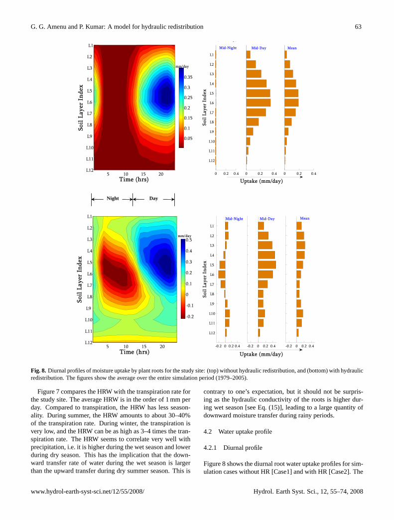
Figure 8: Diurnal profiles of moisture uptake by plant roots for the study site: (top) without hydraulic redistribution, and (bottom) with hydraulic redistribution. The figures show the average over the entire simulation period [1979-2005].
Night Day
Time (hrs)
Soil
Laye
r In
dex
( y)
5 10 15 20
L1
L2
L3
L4
L5
L6
L7
L8
L9
L10
L11
L120 0.2 0.4
L1
L2
L3
L4
L5
L6
L7
L8
L9
L10
L11
L12
Soil
Lay
er I
ndex
0 0.2 0.4
Uptake (mm/day)0 0.2 0.4
0.05
0.1
0.15
0.2
0.25
0.3
0.35
Mid-Night Mid-Day Mean
mm/day
Time (hrs)
Soil
Laye
r In
dex
5 10 15 20
L1
L2
L3
L4
L5
L6
L7
L8
L9
L10
L11
L12-0.2 0 0.2 0.4
L1
L2
L3
L4
L5
L6
L7
L8
L9
L10
L11
L12
Soil
Lay
er I
ndex
-0.2 0 0.2 0.4
Uptake (mm/day)-0.2 0 0.2 0.4
-0.2
-0.1
0
0.1
0.2
0.3
0.4
0.5
Mid-Night Mid-Day Mean
mm/day
Fig. 8. Diurnal profiles of moisture uptake by plant roots for the study site: (top) without hydraulic redistribution, and (bottom) with hydraulicredistribution. The figures show the average over the entire simulation period (1979–2005).
Figure 7 compares the HRW with the transpiration rate forthe study site. The average HRW is in the order of 1 mm perday. Compared to transpiration, the HRW has less season-ality. During summer, the HRW amounts to about 30–40%of the transpiration rate. During winter, the transpiration isvery low, and the HRW can be as high as 3–4 times the tran-spiration rate. The HRW seems to correlate very well withprecipitation, i.e. it is higher during the wet season and lowerduring dry season. This has the implication that the down-ward transfer rate of water during the wet season is largerthan the upward transfer during dry summer season. This is
contrary to one’s expectation, but it should not be surpris-ing as the hydraulic conductivity of the roots is higher dur-ing wet season [see Eq. (15)], leading to a large quantity ofdownward moisture transfer during rainy periods.
4.2 Water uptake profile
4.2.1 Diurnal profile
Figure 8 shows the diurnal root water uptake profiles for sim-ulation cases without HR [Case1] and with HR [Case2]. The
www.hydrol-earth-syst-sci.net/12/55/2008/ Hydrol. Earth Syst. Sci., 12, 55–74, 2008
64 G. G. Amenu and P. Kumar: A model for hydraulic redistribution
two cases provide dramatically different water uptake pro-files. For the case without HR (Fig. 8, top panels), mois-ture movement takes place only from the soil to the root, andhence, the uptake is always positive. For this case, duringnight time, the uptake is negligible because of the stomatalcloser. During day time, water is taken up from all soil lay-ers, and the water uptake profile generally follows the rootdistribution profile. The peak water uptake occurs in the lateafternoon (around 4 pm).
For the case where HR is incorporated into the model for-mulation (see Fig. 8, bottom panels), moisture movement be-tween the soil and the roots is bi-directional, with moistureflow from the soil to the root or vice versa depending on thewater potential gradient. In the figure, negative values in-dicate a moisture movement from the root to the soil, whilepositive values indicate movement from the soil to the root asin Case1. During night, water is transferred from relativelywet part of the soil (in this case, upper and lower soil layers)to dry part of the soil (in this case, the middle soil layers) viaplant roots. During day time, water is taken up from all soillayers. The net water uptake profile, averaged over the entireperiod, shows a disproportionately high water uptake fromthe deeper soil layers with respect to the proportion of rootsin those layers. A noticeable pattern is the nearly uniformuptake of moisture over the vertical profile as compared toCase1 where the uptake is reflective of the profile of the rootdistribution.
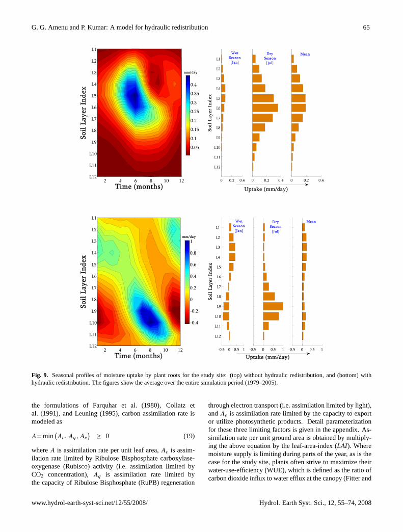
4.2.2 Seasonal profile
Figure 9 shows the seasonal root water uptake profiles for thetwo simulation cases. Similar to the diurnal profiles, we seecompletely different water uptake patterns between the twocases. When the HR is not considered (see Fig. 9, top pan-els), the uptake profile is dictated by the root profile both dur-ing wet and dry seasons. Under this condition, because thetotal uptake is governed by transpiration, the uptake is higherduring dry/summer season than during wet/winter season.During wet season, there is sufficient moisture throughoutthe soil profile and the uptake from each layer is directly con-trolled by the proportion of roots in the layers. As the rainyseason starts to cease, the near surface soil moisture starts todecline at faster rate than the moisture at deeper soil layersbecause of the difference in the root density. As the dry sea-son approaches, the top soil layers get drier while the bottomlayers are still moister. Consequently, during dry season, inaddition to the root fraction, the soil moisture level starts tocontrol the moisture uptake, and the depth of maximum wa-ter uptake will shift down towards regions of more moist soillayers.
For the case with HR (see Fig. 9, bottom panels), the up-take profile does not correlate with the root distribution pro-file. During wet winter season, the upper soil is wetter thanthe deeper soil, and the net moisture transport via plant rootsis downward (from upper soil layers to lower soil layers).
During this time, the moisture transferred to the lower lay-ers is higher than the moisture taken up from these layers,leading to a net moisture release into the soil from the rootat the lower layers (negative uptake). During dry summerseason, the upper soil is drier than the deeper soil, and thenet moisture transport via plant roots is upward, and mois-ture is released into the upper soil layers during night. Theamount of moisture released into the upper soil layers dur-ing night is less than the amount taken up during day timefrom these layers, leading to a net positive moisture uptake.The net moisture uptake from the deeper soil layers duringthe summer is significantly higher than the uptake from theupper soil layer, despite the very small root proportion in thedeeper soil layers.
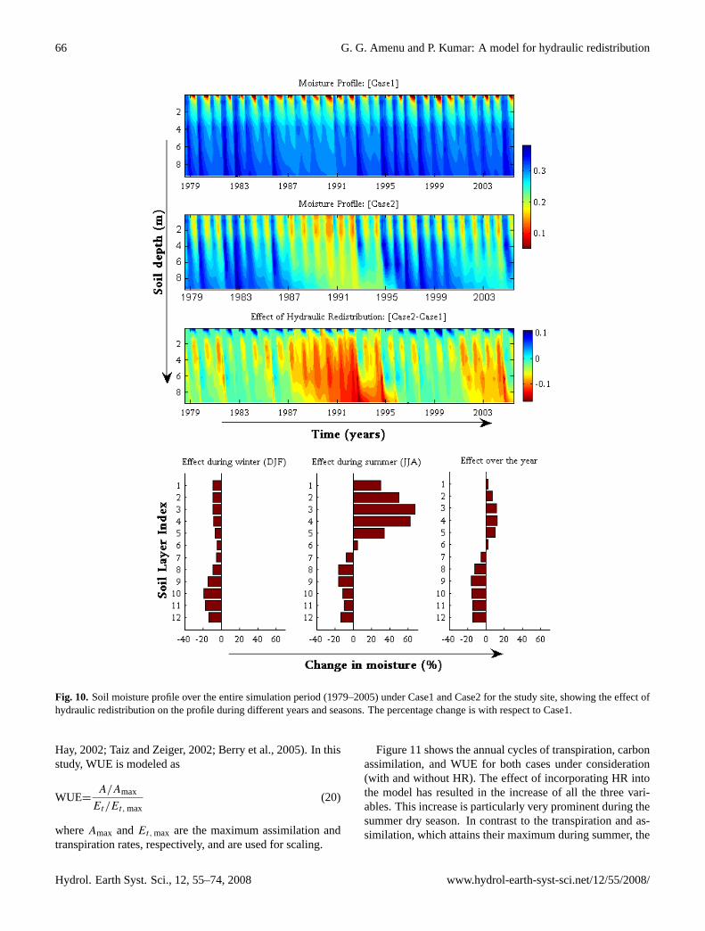
4.3 Soil moisture profile
Figure 10 shows the moisture profile over the entire simu-lation period for both cases, indicating the influence of HRon the seasonal and inter-annual variability of soil moisture.The incorporation of HR has significantly changed the mois-ture profile. The inter-annual variation of the effect of HR onthe soil moisture profile is evident from the plots. The effectis highly pronounced during consequent dry years during themid and the last years of the simulation period. As expected,the HR results in higher net upward moisture transfer duringthe dry years, resulting in reduced moisture in deeper layers.
During wet season, the incorporation of HR causes a netdecrease of moisture content over the whole soil profile (seeFig. 10, bottom-left). The decrease of moisture in the uppersoil layers is due to the net downward transfer of water via theroots during the night (when the stomata close and transpi-ration ceases). However, the amount of moisture transferredfrom the upper to the lower layers is not sufficient to bringthe moisture state of the lower layers to the level when thereis no HR; thus, the deeper soil layers still have a lower soilmoisture content than when there is no HR.
During dry season, the net effect of HR is a significantincrease of moisture in the upper soil layers and a decrease inthe lower soil layers (see Fig. 10, bottom-center). During thisperiod, the deeper soil is often wetter than the shallower soil,leading to a net upward moisture transfer via plant roots andresulting in an increase in moisture in the upper layers and adecrease in the lower layers. The long-term net impact of theHR on soil moisture is an increase of moisture in the uppersoil layers and a decrease in the lower soil layers (see Fig. 10,bottom-right). This leads to a more uniform moisture profileover the soil depth for the simulation with HR compared tothe case without HR.
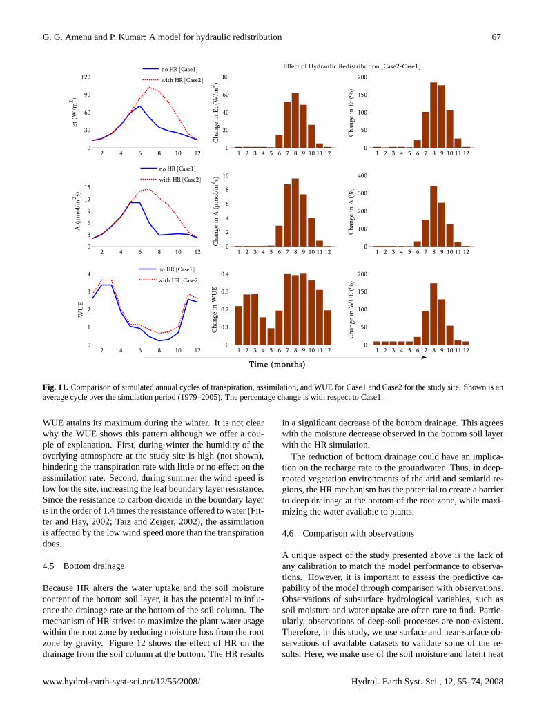
4.4 Transpiration, cCarbon assimilation, and water-use-efficiency
The model for simulating the transpiration rateEt is de-scribed in the Appendix [see Eqs. (A7)–(A22)]. Following
Hydrol. Earth Syst. Sci., 12, 55–74, 2008 www.hydrol-earth-syst-sci.net/12/55/2008/
G. G. Amenu and P. Kumar: A model for hydraulic redistribution 65
56
Figure 9: Seasonal profiles of moisture uptake by plant roots for the study site: (top) without hydraulic redistribution, and (bottom) with hydraulic redistribution. The figures show the average over the entire simulation period [1979-2005].
Time (months)
Soil
Laye
r In
dex
2 4 6 8 10 12
L1
L2
L3
L4
L5
L6
L7
L8
L9
L10
L11
L120 0.2 0.4
L1
L2
L3
L4
L5
L6
L7
L8
L9
L10
L11
L12
Soil
Lay
er I
ndex
0 0.2 0.4
Uptake (mm/day)
0 0.2 0.4
0.05
0.1
0.15
0.2
0.25
0.3
0.35
0.4
WetSeason[Jan]
DrySeason
[Jul]
Mean
mm/day
Time (months)
Soil
Laye
r In
dex
2 4 6 8 10 12
L1
L2
L3
L4
L5
L6
L7
L8
L9
L10
L11
L12-0.5 0 0.5 1
L1
L2
L3
L4
L5
L6
L7
L8
L9
L10
L11
L12
Soil
Lay
er I
ndex
-0.5 0 0.5 1
Uptake (mm/day)-0.5 0 0.5 1
-0.4
-0.2
0
0.2
0.4
0.6
0.8
1
WetSeason[Jan]
DrySeason
[Jul]
Mean
mm/day
Fig. 9. Seasonal profiles of moisture uptake by plant roots for the study site: (top) without hydraulic redistribution, and (bottom) withhydraulic redistribution. The figures show the average over the entire simulation period (1979–2005).
the formulations of Farquhar et al. (1980), Collatz etal. (1991), and Leuning (1995), carbon assimilation rate ismodeled as
A= min(Ac, Aq , Ae
)≥ 0 (19)
whereA is assimilation rate per unit leaf area,Ac is assim-ilation rate limited by Ribulose Bisphosphate carboxylase-oxygenase (Rubisco) activity (i.e. assimilation limited byCO2 concentration),Aq is assimilation rate limited bythe capacity of Ribulose Bisphosphate (RuPB) regeneration
through electron transport (i.e. assimilation limited by light),andAe is assimilation rate limited by the capacity to exportor utilize photosynthetic products. Detail parameterizationfor these three limiting factors is given in the appendix. As-similation rate per unit ground area is obtained by multiply-ing the above equation by the leaf-area-index (LAI). Wheremoisture supply is limiting during parts of the year, as is thecase for the study site, plants often strive to maximize theirwater-use-efficiency (WUE), which is defined as the ratio ofcarbon dioxide influx to water efflux at the canopy (Fitter and
www.hydrol-earth-syst-sci.net/12/55/2008/ Hydrol. Earth Syst. Sci., 12, 55–74, 2008
66 G. G. Amenu and P. Kumar: A model for hydraulic redistribution
57
Figure 10: Soil moisture profile over the entire simulation period [1979-2005] under Case1 and Case2 for the study site, showing the effect of hydraulic redistribution on the profile during different years and seasons. The percentage change is with respect to Case1.
Fig. 10. Soil moisture profile over the entire simulation period (1979–2005) under Case1 and Case2 for the study site, showing the effect ofhydraulic redistribution on the profile during different years and seasons. The percentage change is with respect to Case1.
Hay, 2002; Taiz and Zeiger, 2002; Berry et al., 2005). In thisstudy, WUE is modeled as
WUE=A/Amax
Et/Et,max(20)
whereAmax andEt,max are the maximum assimilation andtranspiration rates, respectively, and are used for scaling.
Figure 11 shows the annual cycles of transpiration, carbonassimilation, and WUE for both cases under consideration(with and without HR). The effect of incorporating HR intothe model has resulted in the increase of all the three vari-ables. This increase is particularly very prominent during thesummer dry season. In contrast to the transpiration and as-similation, which attains their maximum during summer, the
Hydrol. Earth Syst. Sci., 12, 55–74, 2008 www.hydrol-earth-syst-sci.net/12/55/2008/
G. G. Amenu and P. Kumar: A model for hydraulic redistribution 67
58
Figure 11: Comparison of simulated annual cycles of transpiration, assimilation, and WUE for Case1 and Case2 for the study site. Shown is an average cycle over the simulation period [1979-2005]. The percentage change is with respect to Case1.
2 4 6 8 10 120
1
2
3
4
WU
E
1 2 3 4 5 6 7 8 9 10 11 120
0.1
0.2
0.3
0.4
Chan
ge in
WU
E
1 2 3 4 5 6 7 8 9 10 11 120
50
100
150
200
Chan
ge in
WU
E (%
)
2 4 6 8 10 120
30
60
90
120Et
(W/m
2 )
1 2 3 4 5 6 7 8 9 10 11 120
20
40
60
80
Chan
ge in
Et (
W/m
2 )
1 2 3 4 5 6 7 8 9 10 11 120
50
100
150
200
Chan
ge in
Et (
%)
2 4 6 8 10 120
3
6
9
12
15
A (μ
mol
/m2 s)
1 2 3 4 5 6 7 8 9 10 11 120
2
4
6
8
10
Chan
ge in
A (μ
mol
/m2 s)
1 2 3 4 5 6 7 8 9 10 11 120
100
200
300
400
Chan
ge in
A (%
)
no HR [Case1]
with HR [Case2]
no HR [Case1]
with HR [Case2]
no HR [Case1]
with HR [Case2]
Time (months)
Effect of Hydraulic Redistribution [Case2-Case1]
Fig. 11.Comparison of simulated annual cycles of transpiration, assimilation, and WUE for Case1 and Case2 for the study site. Shown is anaverage cycle over the simulation period (1979–2005). The percentage change is with respect to Case1.
WUE attains its maximum during the winter. It is not clearwhy the WUE shows this pattern although we offer a cou-ple of explanation. First, during winter the humidity of theoverlying atmosphere at the study site is high (not shown),hindering the transpiration rate with little or no effect on theassimilation rate. Second, during summer the wind speed islow for the site, increasing the leaf boundary layer resistance.Since the resistance to carbon dioxide in the boundary layeris in the order of 1.4 times the resistance offered to water (Fit-ter and Hay, 2002; Taiz and Zeiger, 2002), the assimilationis affected by the low wind speed more than the transpirationdoes.
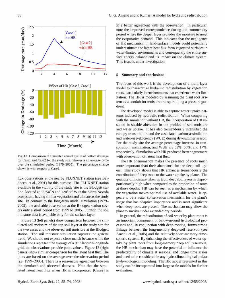
4.5 Bottom drainage
Because HR alters the water uptake and the soil moisturecontent of the bottom soil layer, it has the potential to influ-ence the drainage rate at the bottom of the soil column. Themechanism of HR strives to maximize the plant water usagewithin the root zone by reducing moisture loss from the rootzone by gravity. Figure 12 shows the effect of HR on thedrainage from the soil column at the bottom. The HR results
in a significant decrease of the bottom drainage. This agreeswith the moisture decrease observed in the bottom soil layerwith the HR simulation.
The reduction of bottom drainage could have an implica-tion on the recharge rate to the groundwater. Thus, in deep-rooted vegetation environments of the arid and semiarid re-gions, the HR mechanism has the potential to create a barrierto deep drainage at the bottom of the root zone, while maxi-mizing the water available to plants.
4.6 Comparison with observations
A unique aspect of the study presented above is the lack ofany calibration to match the model performance to observa-tions. However, it is important to assess the predictive ca-pability of the model through comparison with observations.Observations of subsurface hydrological variables, such assoil moisture and water uptake are often rare to find. Partic-ularly, observations of deep-soil processes are non-existent.Therefore, in this study, we use surface and near-surface ob-servations of available datasets to validate some of the re-sults. Here, we make use of the soil moisture and latent heat
www.hydrol-earth-syst-sci.net/12/55/2008/ Hydrol. Earth Syst. Sci., 12, 55–74, 2008
68 G. G. Amenu and P. Kumar: A model for hydraulic redistribution
59
Figure 12: Comparison of simulated annual cycles of bottom drainage for Case1 and Case2 for the study site. Shown is an average cycle over the simulation period [1979-2005]. The percentage change shown is with respect to Case1.
2 4 6 8 10 120
0.5
1
1.5
2
2.5D
rain
age
rate
(m
m/d
ay)
1 2 3 4 5 6 7 8 9 10 11 12-120
-100
-80
-60
-40
-20
0
Cha
nge
in D
rain
age
(%)
Effect of HR [Case2-Case1]
Time (Month)
[Case2]with HR
[Case1]no HR
Fig. 12.Comparison of simulated annual cycles of bottom drainagefor Case1 and Case2 for the study site. Shown is an average cycleover the simulation period (1979–2005). The percentage changeshown is with respect to Case1.
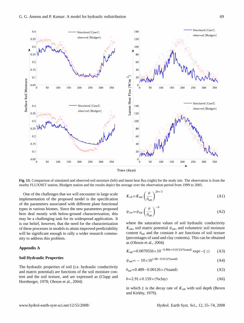
flux observations at the nearby FLUXNET station (see Bal-docchi et al., 2001) for this purpose. The FLUXNET stationavailable in the vicinity of the study site is the Blodgett sta-tion, located at 38◦54′ N and 120◦38′ W in the Sierra Nevadaecosystem, having similar vegetation and climate as the studysite. In contrast to the long-term model simulation (1979–2005), the available observation at the Blodgett station cov-ers only a short period from 1999 to 2005. Further, the soilmoisture data is available only for the surface layer.
Figure 13 (left panels) show comparison between the sim-ulated soil moisture of the top soil layer at the study site forthe two cases and the observed soil moisture at the Blodgettstation. The soil moisture simulation captures the generaltrend. We should not expect a close match because while thesimulations represent the average of a 0.5◦ latitude-longitudegrid, the observations provide point values. Figure 13 (rightpanels) show similar comparison for the latent heat flux. Theplots are based on the average over the observation period[i.e. 1999–2005]. There is a reasonable agreement betweenthe simulated and observed datasets. Note that the simu-lated latent heat flux when HR is incorporated [Case2] is
in a better agreement with the observation. In particular,note the improved correspondence during the summer dryperiod where the deeper layer provides the moisture to meetthe evaporative demand. This indicates that the negligenceof HR mechanism in land-surface models could potentiallyunderestimate the latent heat flux form vegetated surfaces inwater-limited environments and consequently the entire sur-face energy balance and its impact on the climate system.This issue is under investigation.
5 Summary and conclusions
The focus of this work is the development of a multi-layermodel to characterize hydraulic redistribution by vegetationroots, particularly in environments that experience water lim-itation. The HR is modeled by assuming the plant root sys-tem as a conduit for moisture transport along a pressure gra-dient.
The developed model is able to capture water uptake pat-terns induced by hydraulic redistribution. When comparingwith the simulation without HR, the incorporation of HR re-sulted in sizable alteration in the profiles of soil moistureand water uptake. It has also tremendously intensified thecanopy transpiration and the associated carbon assimilationand water-use-efficiency (WUE) during dry-summer season.For the study site the average percentage increase in tran-spiration, assimilation, and WUE are 53%, 56%, and 17%,respectively. Simulation with HR produced better agreementwith observation of latent heat flux.
The HR phenomenon makes the presence of roots muchmore important than their abundance for the deep soil lay-ers. This study shows that HR enhances tremendously thecontribution of deep roots to the water uptake by plants. Thequantity of moisture taken up from deep soil layers is dispro-portionately high when compared to the proportion of rootsat those depths. HR can be seen as a mechanism by whichthe vegetation makes optimal use of available water. It ap-pears to be a water conservation mechanism for the plant’susage that has adaptive importance and is most significantwhen deep roots are present. The mechanism may allow theplant to survive under extended dry periods.
In general, the redistribution of soil water by plant roots isan important component of below-ground hydrological pro-cesses and, in conjunction with deep-rooting, forms stronglinkage between the long-memory deep-soil reservoir (seeAmenu et al., 2005) and the relatively short-memory atmo-spheric system. By enhancing the effectiveness of water up-take by plant roots from long-memory deep soil reservoirs,the HR mechanism may have the potential to influence thepredictability of climate at seasonal and longer time scalesand need to be considered in any hydroclimatological and/orhydroecological modeling. The HR model presented in thisstudy can be incorporated into large scale models for furtherevaluation.
Hydrol. Earth Syst. Sci., 12, 55–74, 2008 www.hydrol-earth-syst-sci.net/12/55/2008/
G. G. Amenu and P. Kumar: A model for hydraulic redistribution 69
60
Figure 13: Comparison of simulated and observed soil moisture (left) and latent heat flux (right) for the study site. The observation is from the nearby FLUXNET station, Blodgett station and the results depict the average over the observation period from 1999 to 2005.
0 50 100 150 200 250 300 3500.05
0.1
0.15
0.2
0.25
0.3
0.35
0.4
0 50 100 150 200 250 300 3500
20
40
60
80
100
120
140
0 50 100 150 200 250 300 3500.05
0.1
0.15
0.2
0.25
0.3
0.35
0.4
Surf
ace
Soil
Moi
stur
e
0 50 100 150 200 250 300 3500
20
40
60
80
100
120
140
Late
nt H
eat
Flux
(W
/m2 )
Simulated [Case2]
observed [Blodgett]
Simulated [Case1]
observed [Blodgett]
Simulated [Case2]
observed [Blodgett]
Simulated [Case1]
observed [Blodgett]
Time (days)
Fig. 13. Comparison of simulated and observed soil moisture (left) and latent heat flux (right) for the study site. The observation is from thenearby FLUXNET station, Blodgett station and the results depict the average over the observation period from 1999 to 2005.
One of the challenges that we will encounter in large scaleimplementation of the proposed model is the specificationof the parameters associated with different plant functionaltypes in various biomes. Since the new parameters proposedhere deal mostly with below-ground characterization, thismay be a challenging task for its widespread application. Itis our belief, however, that the need for the characterizationof these processes in models to attain improved predictabilitywill be significant enough to rally a wider research commu-nity to address this problem.
Appendix A
Soil Hydraulic Properties
The hydraulic properties of soil (i.e. hydraulic conductivityand matrix potential) are functions of the soil moisture con-tent and the soil texture, and are expressed as (Clapp andHornberger, 1978; Oleson et al., 2004)
Ksh=Ksat
(θ
θsat
)2b+3
(A1)
ψsm=ψsat
(θ
θsat
)−b
(A2)
where the saturation values of soil hydraulic conductivityKsat, soil matric potentialψsat, and volumetric soil moisturecontentθsat and the constantb are functions of soil texture(percentages of sand and clay contents). This can be obtainedas (Oleson et al., 2004)
Ksat=0.0070556×10−0.884+0.0153(%sand) exp(−ξ z) (A3)
ψsat= − 10×101.88−0.013(%sand) (A4)
θsat=0.489−0.00126×(%sand) (A5)
b=2.91+0.159×(%clay) (A6)
in which ξ is the decay rate ofKsat with soil depth (Bevenand Kirkby, 1979).
www.hydrol-earth-syst-sci.net/12/55/2008/ Hydrol. Earth Syst. Sci., 12, 55–74, 2008
70 G. G. Amenu and P. Kumar: A model for hydraulic redistribution
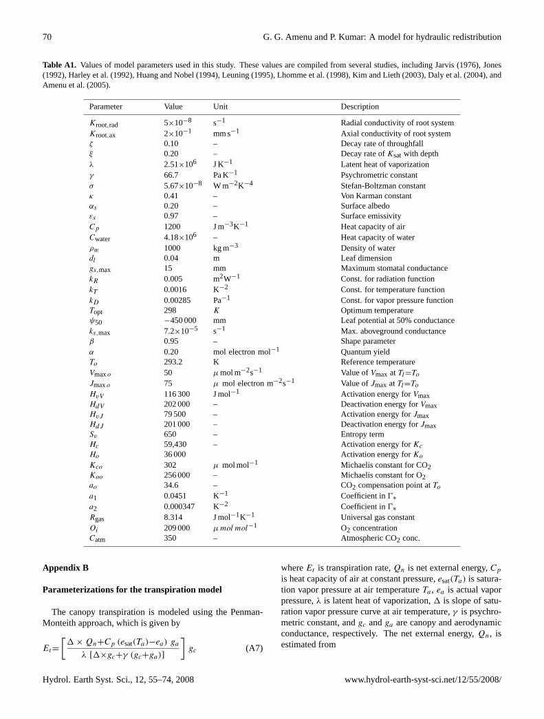
Table A1. Values of model parameters used in this study. These values are compiled from several studies, including Jarvis (1976), Jones(1992), Harley et al. (1992), Huang and Nobel (1994), Leuning (1995), Lhomme et al. (1998), Kim and Lieth (2003), Daly et al. (2004), andAmenu et al. (2005).
Parameter Value Unit Description
Kroot,rad 5×10⁻⁸ s−1 Radial conductivity of root systemKroot,ax 2×10⁻¹ mm s−1 Axial conductivity of root systemζ 0.10 – Decay rate of throughfallξ 0.20 – Decay rate ofKsatwith depthλ 2.51×10⁶ J K−1 Latent heat of vaporizationγ 66.7 Pa K−1 Psychrometric constantσ 5.67×10⁻⁸ W m−2K−4 Stefan-Boltzman constantκ 0.41 – Von Karman constantαs 0.20 – Surface albedoεs 0.97 – Surface emissivityCp 1200 J m−3K−1 Heat capacity of airCwater 4.18×10⁶ – Heat capacity of waterρw 1000 kg m−3 Density of waterdl 0.04 m Leaf dimensiongs,max 15 mm Maximum stomatal conductancekR 0.005 m2W−1 Const. for radiation functionkT 0.0016 K−2 Const. for temperature functionkD 0.00285 Pa−1 Const. for vapor pressure functionTopt 298 K Optimum temperatureψ50 −450 000 mm Leaf potential at 50% conductanceks,max 7.2×10⁻⁵ s−1 Max. aboveground conductanceβ 0.95 – Shape parameterα 0.20 mol electron mol−1 Quantum yieldTo 293.2 K Reference temperatureVmaxo 50 µmol m−2s−1 Value ofVmax atTl=ToJmaxo 75 µ mol electron m−2s−1 Value ofJmax atTl=ToHvV 116 300 J mol−1 Activation energy forVmaxHdV 202 000 – Deactivation energy forVmaxHvJ 79 500 – Activation energy forJmaxHdJ 201 000 – Deactivation energy forJmaxSv 650 – Entropy termHc 59,430 – Activation energy forKcHo 36 000 Activation energy forKoKco 302 µ mol mol−1 Michaelis constant for CO2Koo 256 000 – Michaelis constant for O2ao 34.6 – CO2 compensation point atToa1 0.0451 K−1 Coefficient in0∗
a2 0.000347 K−2 Coefficient in0∗
Rgas 8.314 J mol−1K−1 Universal gas constantOi 209 000 µmol mol−1 O2 concentrationCatm 350 – Atmospheric CO2 conc.
Appendix B
Parameterizations for the transpiration model
The canopy transpiration is modeled using the Penman-Monteith approach, which is given by
Et=
[1×Qn+Cp (esat(Ta)−ea) ga
λ [1×gc+γ (gc+ga)]
]gc (A7)
whereEt is transpiration rate,Qn is net external energy,Cpis heat capacity of air at constant pressure,esat(Ta) is satura-tion vapor pressure at air temperatureTa , ea is actual vaporpressure,λ is latent heat of vaporization,1 is slope of satu-ration vapor pressure curve at air temperature,γ is psychro-metric constant, andgc andga are canopy and aerodynamicconductance, respectively. The net external energy,Qn, isestimated from
Hydrol. Earth Syst. Sci., 12, 55–74, 2008 www.hydrol-earth-syst-sci.net/12/55/2008/
G. G. Amenu and P. Kumar: A model for hydraulic redistribution 71
Qn=(1 − αs)Rs+σ(εaT4ref−εsT
4s )− Csoil
1Ta
1tze (A8)
whereRs is incoming solar radiation,αs is surface albedo,σis Stefan-Boltzman constant,Tref is air temperature at refer-ence height (taken to be 30 m above the surface),Ts is surfacetemperature (here, assumed equal to air temperature at 2 mheight),εs is surface emissivity, andεa is atmospheric emis-sivity at reference height,Csoil is soil heat capacity,1Ta ischange in air temperature over time interval1t , andze is soildepth that a temperature wave penetrates over time1t (here,assumed equal to the thickness of the top soil layer). Follow-ing Amenu et al. (2005), the expressions for estimating1,esat, ga , εa , andCsoil are as follows
1=
(4098
(237.3+Ta)2
)×esat(Ta) (A9)
esat(T )=611 exp
(17.27(T−273.15)
T − 35.85
)(A10)
ga=κ2U
[ln
(zU − do
zom
). ln
(zT−do
zoh
)]−1
(A11)
εa=0.642
(esat(Ta)
Ta
)1/7
(A12)
Csoil=Csolid(1 − θsat)+Cwaterθ (A13)
Csolid=
(2.128(% sand)+2.385(% clay)
(%sand)+(% clay)
)×106 (A14)
whereκ is von Karman constant,U is wind speed,do is zeroplane displacement height(≈ 0.667hveg), zom and zoh areroughness length for momentum and heat transfer, respec-tively (≈0.136hveg), hveg is vegetation height,Csolid is theheat capacity of the soil solid matrix, andCwater is the heatcapacity of the soil water. The canopy conductancegc (perunit ground area) is modeled as
gc=
(gsgb
gs+gb
)LAI (A15)
whereLAI is leaf-area-index,gs is stomatal conductance perunit leaf area, andgb is leaf boundary layer conductance perunit leaf area, which can be estimated with adequate preci-sion using (Jones, 1992)
gb=0.00662
(U
dl
)0.5
(A16)
wheredl is leaf characteristic dimension. The stomatal con-ductancegs (per unit leaf area) is modeled based on Jarvis’approach (Jarvis, 1976), which is given by
gs=gsmax . f (R) . f (T ) . f (ψ) . f (D) . f (C) (A17)
wheregsmax is maximum stomatal conductance per unit leafarea, andf (R), f (T ), f (ψ), f (D), andf (C) are factors
(varying between 0 and 1) that account for the constraintsimposed on stomatal conductance by the radiation, tempera-ture, leaf water status, humidity, and CO2 concentration, re-spectively. They are parameterized as (Noilhan and Planton,1989; Jones, 1992; Leuning, 1995; Lhomme et al., 1998)
f (R)=1− exp(−kRRs) (A18)
f (T )=1−kT(Ta−Topt
)2 (A19)
f (ψ)=
[1+
(ψleaf
ψ50
)n]−1
(A20)
f (D)=1
1+kDD(A21)
wherekR, kT , kD, andn are empirical constants,Topt is theair temperature at which the conductance attains maximum,ψleaf is leaf water potential,ψ50 is the value of leaf water po-tential at whichf (ψ) is 50% of its maximum, andD vaporpressure deficit (D=es − ea). Because CO2 concentration ina natural environment is relatively constant over time (Jones,1992), the factorf (C) is assumed equal to 1. The leaf waterpotential is linked to the soil water potential and the transpi-ration rate through
ψleaf=ψsoil−ho
(1+
1
KshootEt
)(A22)
whereKshoot is the above ground plant hydraulic conduc-tivity (per unit ground area), andho is the reference heightfor leaf location above the soil surface (approximated as≈0.80hveg).
Appendix C
Parameterizations for the photosynthesis model
The carbon-limitedAc, light-limited Aq , and export-limitedAe assimilation rates are given by
Ac=Vmax
Ci−0∗
Ci+Kc
(1+
OiKo
) , Ci−0∗≥0 (A23)
Aq=J
4
[Ci−0∗
Ci+20∗
], Ci−0∗≥0 (A24)
Ae=1
2Vmax (A25)
whereVmax is the maximum carboxylation rate,Kc andKoare the Michaelis-Menten coefficients for CO2 and O2, 0∗
is the CO2 compensation point in the absence of respiration,Ci andOi are internal leaf CO2 and O2 concentration, re-spectively, andJ is the electron transport rate for a givenabsorbed photon irradiance and is given by the smaller root
www.hydrol-earth-syst-sci.net/12/55/2008/ Hydrol. Earth Syst. Sci., 12, 55–74, 2008
72 G. G. Amenu and P. Kumar: A model for hydraulic redistribution
of the following quadratic equation (Leuning, 1995; Daly etal., 2004),
βJ 2− (αQ+Jmax) J+αQJmax=0 (A26)
whereβ andα are constants andJmax is the maximum rateof electron transport. The parametersVmax, Jmax, Kc, Ko,and0∗ are all functions of leaf temperature,Tl , (Farquharet al., 1980; Harley et al., 1992; Leuning, 1995; Daly et al.,2004), and are expressed as follows:
Vmax=Vmaxo
exp[HvVRgasTo
(1−
ToTl
)]1+ exp
(SvTl−HdVRgasTl
) (A27)
Jmax=Jmaxo
exp[HvJRgasTo
(1−
ToTl
)]1+ exp
(SvTl−HdJRgasTl
) (A28)
Kc=Kco exp
[Hc
RgasTo
(1−To
Tl
)](A29)
Ko=Koo exp
[Ho
RgasTo
(1−To
Tl
)](A30)
0∗=ao
(1+a1(Tl−To)+a2(Tl−To)
2)
(A31)
where the terms are as defined in Table A1. In the above for-mulations, the effect of leaf water status on assimilation rateis not taken into consideration. However, such dependence iscrucial for studies focusing on water-limited ecosystems. Inthis study Eq. (20) is reformulated as
A=f (ψ).min(Ac, Aq , Ae
)≥0 (A32)
where the functionf (ψ) takes care of the water/moisturelimitation on assimilation rate, and is assumed to take thesame form as Eq. (A20). The intercellular CO2 concentrationCi , which is used in the calculation of the assimilation rate[see Eqs. (A23) and (A24)], is estimated from the solution of
C2i+(g.Vmax−Catm+O)Ci−(g.Vmax0∗+O.Catm)=0 (A33)
where
O=Kc
(1 +
OiKo
)g=
(1.65gs
+1.37gb
) (RgasTatmPatm
) (A34)
in whichCatm is atmospheric CO2 concentration,Rgasis uni-versal gas constant, andPatm is atmospheric pressure at tem-peratureTatm. The leaf temperature,Tl , is approximated us-ing 1st-order solution of the energy balance equation, whichis given by
Tl=Ta+
(1−αs)Rs+(εa−εs)σT4a −G−
Cpγ
(gcgagc+ga
)(esat(Ta)−ea)
4εsσT 3a +Cp
(1γ
gcgagc+ga
+ga
) (A35)
where the variables are as defined before. The values of thevarious parameters of the model described above are given inTable A1.
Acknowledgements.Support for this research is provided by theNational Oceanic and Atmospheric Administration (NOAA) undergrants NA 03-OAR4310070 and NA 06-OAR4310053 and theNational Science Foundation (NSF) under grant ATM 06-28687.
Edited by: S. Manfreda
References
Amenu, G. G.: Deep-layer terrestrial hydrologic memory andmechanisms of its influence on the eco-climatology of the bio-sphere, Ph.D. Dissertation, University of Illinois, Urbana, 365pp., 2007.
Amenu, G. G., Kumar, P., and Liang, X.-Z.: Interannual variabilityof deep-layer hydrologic memory and its influence on surfaceenergy fluxes, J. Climate, 18, 5024–5045, 2005.
Baker, J. M., van Bavel, C. H. M.: Water transfer through cottonplants connecting soil regions of differing water potential, Agron.J., 80, 993–997, 1988.
Baldocchi, D., Falge, E., Gu, L., and et al.: FLUXNET: A new toolto study the temporal and spatial variability of ecosystem-scalecarbon dioxide, water vapor, and energy flux densities, B. Am.Meteorol. Soc., 82, 2415–2434, 2001.
Berry, S. L., Farquhar, F. D., and Roderick, M. L.: Co-evolutionof climate, vegetation, soil and air, in: Encyclopedia of Hydro-logical Sciences, 177–192, Volume 1: Theory, organisation andscale, edited by: Bloschl, G. and Sivapalan, M., John Wiley andSons Ltd, Chichester, UK, 2005.
Beven, K. J. and Kirkby, M. J.: A physically based, variable con-tributing area model of basin hydrology, Hydrol. Sci. B., 24, 43–69, 1979.
Brooks, J. R., Meinzer, F. C., Coulombe, R., and Gregg, J.: Hy-draulic redistribution of soil water during summer drought in twocontrasting Pacific Northwest coniferous forests, Tree Physiol.,22, 1107–1117, 2002.
Brooks, J. R., Meinzer, F. C., Warren, J. M., Domec, J.-C., andCoulombe, R.: Hydraulic redistribution in a Douglas-fir forest:lessons from system manipulations, Plant. Cell Environment, 29,138–150, 2006.
Bonan, G. B., Levis, S., Kergoat, L., and Oleson, K.W.: Land-scapes as patches of plant functional types: An integrating con-cept for climate and ecosystem models, Global Biogeochem. Cy.,16, 5.1–5.23, 2002.
Burgess, S. S. O., Adams, M. A., Turner, N. C., and Ong, C. K.:The redistribution of soil water by tree root systems, Oecologia,115, 306–311, 1998.
Burgess, S. S. O., Pate, J. S., Adams, M. A., and Dawson, T. E.:Seasonal water acquisition and redistribution in the Australianwoody phreatophyteBanksia prionotes, Ann. Bot.-London, 85,215–224, 2000.
Burgess, S. S. O., Adams, M. A., Turner, N. C., White, D. A., andOng, C. K.: Tree roots: conduits for deep recharge of soil water,Oecologia, 26, 158–165, 2001.
Hydrol. Earth Syst. Sci., 12, 55–74, 2008 www.hydrol-earth-syst-sci.net/12/55/2008/
G. G. Amenu and P. Kumar: A model for hydraulic redistribution 73
Caldwell, M. M., Dawson, T. E., and Richards, J. H.: Hydraulic lift:consequences of water efflux from the roots of plants, Oecologia,113, 151-161, 1998.
Caldwell, M. M. and Richards, J. H.: Hydraulic lift: water effluxfrom upper roots improves effectiveness of water uptake by deeproots, Oecologia, 79, 1-5, 1989.
Campbell, G. S.: Simulation of Water Uptake by Plant Roots,in: Modeling Plant and Soil Systems, edited by Hanks, J. andRitchie, J.T., American Society of Agronomy Inc, Madison, Wis-consin, 1–545, 1991.
Canadell, J., Jackson, R. B., Ehleringer, J. R., Mooney, H. A., Sala,O. E., and Schulze, E. D.: Maximum rooting depth of vegetationtypes at the global scale, Oecologia, 108, 583–595, 1996.
Cannon, W. A.: Specialization in vegetation and in environment inCalifornia, Plant World, 17, 223–237, 1914.
Clapp, R. B. and Hornberger, G. M.: Empirical equations for somesoil hydraulic properties, Water Resour. Res., 14, 601–604, 1978.
Collatz, G. J., Ball, J. T., Grivet, C., and Berry, J. A.: Physiologi-cal and environmental regulation of stomatal conductance, pho-tosynthesis, and transpiration: A model that includes a laminarboundary layer, Agr. Forest Meteorol., 54, 107–136, 1991.
Corak, S. J., Blevins, D. G., and Pallardy, S. G.: Water transferin alfalfa/maize association: survival of maize during drought,Plant Physiol., 84, 582–586, 1987.
Dai, Y., Zeng, X., Dickinson, R. E., and et al.: The common landmodel, B. Am. Meteorol. Soc., 84, 1013–1023, 2003.
Daly, E., Porporato, A., and Rodriguez-Iturbe, I.: Coupled dynam-ics of photosynthesis, transpiration, and soil water balance, Part-I: Upscaling from hourly to daily level, J. Hydrometeorol., 5,546–558, 2004.
Dawson, T. E.: Hydraulic lift and water use by plants: implicationsfor water balance, performance and plant-plant interactions, Oe-cologia, 95, 565–574, 1993.
Dawson, T. E.: Determining water use by trees and forests fromisotopic, energy balance and transpiration analysis: the roles oftree size and hydraulic lift, Tree Physiol., 16, 263–272, 1996.
Dawson, T. E. and Pate, J. S.: Seasonal water uptake and movementin root systems of Australian phraeatophytic plants of dimorphicroot morphology: a stable isotope investigation, Oecologia, 107,13–20, 1996.
Dixon, H. H.: Transpiration and the ascent of sap in plants, MacMil-lan, London, 216 pp., 1914.
DeSouza, J., Silka, P. A., and Davis, S. D.: Comparative physiologyof burned and unburnedRhus laurinaafter chaparral wildfire,Oecologia, 71, 63–68, 1986.
Emerman, S. H. and Dawson, T. E.: Hydraulic lift and its influenceon the water content of the rhizosphere: an example from sugarmaple,Acer saccharum, Oecologia, 108, 273–278, 1996.
Espeleta, J. F., West, J. B., and Donovan, L. A.: Species-specificpatterns of hydraulic lift in co-occurring adult trees and grassesin a sandhill community, Oecologia, 138, 341–349, 2004.
Farquhar, G. D., von Caemmerer, S., and Berry, J. A.: A biochem-ical model of photosynthetic CO2 assimilation in leaves of Cspecies, Planta, 149, 78–90, 1980.
Fiscus, E. L.: The interaction between osmotic- and pressure-induced water flow in plant roots, Plant Physiol., 55, 917–922,1975.
Fitter, A. H. and Hay, R. K. M.: Environmental physiology ofplants, Academic Press, London, 3. Ed., 1–367, 2002.
Frensch, J. and Steudle, E.: Axial and radial hydraulic resistance toroots of maize, Plant Physiol., 91, 719–726, 1989.
Gregory, P. J.: Plant Roots: Growth, activity, and interactions withthe soils, Blackwell Publishing, Oxford, 1–318, 2006.
Gurevitch, J., Scheiner, S. M., and Fox, G. A.: The ecology ofplants, Sinauer Associates, Inc., Sunderland, Massachusetts, 1–523, 2002.
Harley, P. C., Thomas, R. B., Reynolds, J. F., and Strain, B. R.:Modelling photosynthesis of cotton grown in elevated CO2, PlantCell Environ., 15, 271–282, 1992.
Hacke, U. G., Sperry, J. S., Wheeler, J. K., and Castro, L.: Scalingof angiosperm xylem structure with safety and efficiency, TreePhysiol., 26, 689–832, 2006.
Hellmers, H., Horton, J. S., Juhren, G., and O’Keefe, J.: Root sys-tems of some chaparral plants in southern California, Ecology,36, 667–678, 1955.
Huang, B. and Nobel, P. S.: Root hydraulic conductivity and itscomponents, with emphasis on desert succulents, Agron. J., 86,767–774, 1994.
Hultine, K. R., Cable, W. L., Burgess, S. S. O., and Williams, D. G.:Hydraulic redistribution by deep roots of a Chihuahuan Desertphreatophyte, Tree Physiol., 23, 353–360, 2003.
Hultine, K. R., Scott, R. L., Cable, W. L., Goodrich, D. C., andWilliams, D. G.: Hydraulic redistribution by a dominant, warm-desert phreatophyte: seasonal patterns and response to precipita-tion pulses, Funct. Ecol., 18, 530–538, 2004.
Jackson, R. B., Moore, L. A., Hoffmann, W. A., Pockman, W. T.,and Linder, C. R.: Ecosystem rooting depth determined withcaves and DNA, Proc. Natl. Acad. Sci., 96, 11 387–11 392, 1999.
Jarvis, P. G.: The interpretation of the variations in leaf water po-tential and stomatal conductance found in canopies in the field,Philos. Tr. R. Soc. B, 273, 593–610, 1976.
Jones, H. G.: Plants and Microclimate: A quantitative approachto environmental plant physiology, Cambridge University Press,Cambridge, 2. Ed., 1–428, 1992.
Kim, S.-H. and Lieth, J. H.: A Coupled model of photosynthesis,stomatal conductance and transpiration for a rose leaf, Ann. Bot.-London, 91, 771–781, 2003.
Kramer, P. J.: The absorption of water by the root systems of plants,Am. J. Bot., 19, 148–164, 1932.
Kramer, P. J. and Boyer, J. S.: Water relations of plants and soils,Academic Press, 2. Ed., San Diego, 1–495, 1995.
Kundu, P. K. and Cohen, I. M.: Fluid mechanics, Academic Press,2. Ed., San Diego, 1–730, 2002.
Lee, J.-E., Oliveira, R. S., Dawson, T. E., and Fung, I.: Root func-tioning modifies seasonal climate, P. Natl. Acad. Sci-Biol., 102,17 576–17 581, 2005.
Leffler, A. J., Peek, M. S., Ryel, R. J., Ivans, C. Y., and Cald-well, M. M.: Hydraulic redistribution through the root systemsof Senesced plants, Ecology, 86, 633–642, 2005.
Leuning, R.: A critical appraisal of a combined stomatal-photosynthesis model for C3 plants, Plant Cell Environ., 18,339–355, 1995.
Lewis, D. C. and Burgy, R. H.: The relationship between oak treeroots and ground water in fractured rock as determined by tritiumtracing, J. Geophys. Res., 69, 2579–2588, 1964.
Lhomme, J. P., Elguero, E., Chehbouni, A., and Boulet, G.: Stom-atal control of transpiration: examination of Monteith’s formu-lation of canopy resistance, Water Resour. Res., 34, 2301–2308,
www.hydrol-earth-syst-sci.net/12/55/2008/ Hydrol. Earth Syst. Sci., 12, 55–74, 2008
74 G. G. Amenu and P. Kumar: A model for hydraulic redistribution
1998.Liang, X., Lettenmaier, D. P., Wood, E. F., and Burges, S. J.: A
simple hydrologically based model of land surface water and en-ergy fluxes for general circulation models, J. Geophys. Res., 99,14 415–14 428, 1994.
Lopez, F. and Nobel, P. S.: Root hydraulic conductivity of two cac-tus species in relation to root age, temperature, and soil waterstatus, J. Exp. Bot., 42, 143–149, 1991.
Loveland, T. R., Reed, B. C., Brown, J. F., Ohlen, D. O., Zhu, Z.,Yang, L., and Merchant, J. W.: Development of a global land-cover characteristics database and IGBP DISCover from 1 kmAVHRR data, Int. J. Remote Sens., 21, 1303–1330, 2000.
Ludwig, F., Dawson, T. E., Kroon, H., Berendse, F., and Prins, H.H.T.: Hydraulic lift in Acacia tortilis trees on an East African sa-vanna, Oecologia, 134, 293–300, 2003.
Mesinger, F., DiMego, G., Kalnay, E., and et al.: North AmericanRegional Reanalysis, B. Am. Meteorol. Soc., 87, 343–360, 2006.
Millikin, I. C. and Bledsoe, C. S.: Seasonal and diurnal patterns ofsoil water potential in the rhizosphere of blue oaks: evidence forhydraulic lift, Oecologia, 125, 459–465, 2000.
Monteith, J. L. and Unsworth, M. H.: Principles of environmentalphysics, Edward Arnold, London, 2. Ed., 1–291, 1990.
Moreira, M. Z., Scholz, F. G., Bucci, S. J., Sternberg, L. D., Gold-stein, G. H., Meinzer, F. C., and Franco, A. C.: Hydraulic lift ina neotropical savanna, Funct. Ecol., 17, 573–581, 2003.
Mooney, A., Ehrlich, P. R., Lincoln, D. E., and Williams, K. S.:Environmental controls on the seasonality of a drought decid-uous shrub,Diplacus aurantiacusand its predator, the check-erspot butterfly,Euphydryas chalcedona. Ibid., Oecologia, 45,143–146, 1980.
Nobel, P. S., Schulte, P. J., and North, G. B.: Water influx char-acteristics and hydraulic conductivity for root ofAgave desertiEngelm., J. Exp. Bot., 41, 409–415, 1990.
Noilhan, J. and Planton, S.: A simple parameterization of land sur-face processes for meteorological models, Month. Weather Rev.,117, 536–549, 1989.
Oleson, K. W., Dai, Y., Bonan, G., and et al.: Technical descriptionof the community land model (CLM), NCAR Technical Note,Boulder, CO, 1–174, 2004.
Oliveira, R. S., Dawson, T. E., Burgess, S. S. O., and Nepstad, D.C.: Hydraulic redistribution in three Amazonian trees, Oecolo-gia, 145, 354–363, 2005.
Pate, J. S., Jeschke, W. D., and Aylward, M. J.: Hydraulic architec-ture and xylem structure of the dimorphic root systems of south-west Australian species of Proteaceae, J. Exp. Bot., 46, 907–915,1995.
Philip, J. R.: Plant water relations: some physical aspects, Ann.Rev. Plant Physio., 17, 245–268, 1966.
Ren, D., Xue, M., and Henderson-Sellers, A.: Incorporating hy-draulic lift into a land surface model and its effects on surfacesoil moisture prediction, J. Hydrometeorol., 5, 1181–1191, 2004.
Richards, J. H. and Caldwell, M. M.: Hydraulic lift: substantialnocturnal water transport between soil layers byArtemisia tri-dentataroots, Oecologia, 73, 486–489, 1987.
Ryel, R. J., Caldwell, M. M., Yoder, C. K., Or, D., and Leffler, A.J.: Hydraulic redistribution in a stand ofArtemisia tridentata:evaluation of benefits to transpiration assessed with a simulationmodel, Oecologia, 130, 173–184, 2002.
Schenk, H. J. and Jackson, R. B.: The global biogeography of roots,Ecol. Monogr., 72, 311–328, 2002.
Schulze, E.-D., Caldwell, M. M., Canadell, J., Mooney, H. A., Jack-son, R. B., Parson, D., Scholes, R., Sala, O. E., and Trimborn, P.:Downward flux of water through roots (i.e. inverse hydraulic lift)in dry Kalahari sands, Oecologia, 115, 460–462, 1998.
Smith, D. M., Jackson, N. A., Roberts, J. M., and Ong, C. K.: Re-verse flow of sap in tree roots and downward siphoning of waterby Grevillae robusta, Funct. Ecol., 13, 256–264, 1999.
Song, Y., Kirkham, M. B., Ham, J. M., and Kluitenberg, G. J.: Root-zone hydraulic lift evaluated with the dual-probe heatpulse tech-nique, Aust. J. Soil Res., 38, 927–935, 2000.
Steudle, E.: Water uptake by plant roots: an integration of views,Plant Soil, 226, 45–56, 2000.
Steudle, E. and Frensch, J.: Water transport in plants: role of theapoplast, Plant Soil, 187, 67–79, 1996.
Steudle, E. and Peterson, C. A.: How does water get through roots?,J. Exp. Bot., 49, 775–788, 1998.
Stone, E. L. and Kalisz, P. J.: On the maximum extent of tree roots,Forest Ecol. Manag., 46, 59–102, 1991.
Taiz, L. and Zeiger, E.: Plant Physiology, Sinauer Assoc. Inc. Publ.,Sunderland, Mass., 3rd edition, 1–690, 2002.
Thomas, C. M. and Davis, S. D.: Recovery patterns of threechaparral shrub species after wildfire, Oecologia, 80, 309–320,1989.
Tyree, M. T. and Zimmermann, M. H.: Xylem structure and theascent of sap., Springer-Verlag, 2. Ed., Berlin, 250 pp., 2002.
Van Bavel, C. H. M. and Baker, J. M.: Water transfer by plant rootsfrom wet to dry soil, Naturwissenschaften, 72, 606–607, 1985.
Van den Honert, T. H.: Water transport as a catenary process, Dis-cuss. Faraday Soc., 3, 146–153, 1948.
Wan, C., Sosebee, R. E., and McMichael, B. L.: Hydraulic prop-erties of shallow vs. deep lateral roots in semiarid shrub, Gutier-rezia sarothrae, Am. Midl. Nat., 131, 120–127, 1994.
Wan, C., Sosebee, R. E., and McMichael, B. L.: Does hydraulic liftexist in shallow-rooted species? A quantitative examination witha half-shrubGutierrezia sarothrae, Plant Soil, 153, 11–17, 1993.
Wan, C., Xu, W., Sosebee, R. E., Machado, S., and Archer, T.: Hy-draulic lift in drought-tolerant and -susceptible maize hybrids,Plant Soil, 219, 117–126, 2000.
Wetzel, P. J. and Boone, A.: A parameterization for land-atmosphere-cloud-exchange (PLACE): documentation and test-ing of a detailed process model of the partly cloudy boundaryover heterogeneous land, J. Climate, 8, 1810–1837, 1995.
Yoder, C. K. and Nowak, R. S.: Hydraulic lift among native plantspecies in the Mojave Desert, Plant Soil, 215, 93–102, 1999.
Hydrol. Earth Syst. Sci., 12, 55–74, 2008 www.hydrol-earth-syst-sci.net/12/55/2008/