Embed Size (px)
Citation preview
Journal of Network and Computer Applications 36 (2013) 1551–1565
Contents lists available at ScienceDirect
Journal of Network and Computer Applications
1084-80http://d
n CorrE-m
AnaIsabMiguel.
journal homepage: www.elsevier.com/locate/jnca
A model-driven and task-oriented method for the developmentof collaborative systems
Jesús Gallardo a,n, Ana I. Molina b, Crescencio Bravo b, Miguel A. Redondo b
a Department of Computer and Systems Engineering, University of Zaragoza, Spainb Department of Information Technologies and Systems, University of Castilla—La Mancha, Spain
a r t i c l e i n f o
Article history:Received 14 August 2012Received in revised form19 December 2012Accepted 21 March 2013Available online 17 April 2013
Keywords:Model-driven software developmentGroupware developmentModel-based user interface development
45/$ - see front matter & 2013 Elsevier Ltd. Ax.doi.org/10.1016/j.jnca.2013.03.016
esponding author. Tel.: +34 978645387.ail addresses: [email protected] (J. [email protected] (A.I. Molina), [email protected] (M.A. Redondo).
a b s t r a c t
Groupware systems are usually difficult to design when following traditional methodologies andapproaches for single user systems. In this regard, model-driven approaches have been gaining attentionin recent years. In accordance with this paradigm, we developed the SpacEclipse method in a previouswork, which is a method for developing collaborative modeling groupware based on the plug-ins in theEclipse Modeling Project. However, this method presents some deficiencies that we have tried toovercome in this work. In order to achieve this goal, we have chosen the CIAM methodology, whichallows the modeling of collaboration, users, tasks, sessions and interactive issues and which is alsosupported by Eclipse-based tools. In this paper, we explain how the integration of CIAM elements in theSpacEclipse method has been carried out and resulted in a new method with its own methodological,conceptual and technological frameworks. To prove the validity of the method, we have applied it to are-engineering process in the development of an existing tool.
& 2013 Elsevier Ltd. All rights reserved.
1. Introduction
The use of applications to support communication, coordinationand collaboration among people is increasing exponentially. Whendeveloping groupware systems we can adopt different approaches:(a) a handmade ad hoc development, in which the systems are builtcompletely tailored to the specific problem; (b) the use of toolkits,APIs or components which provide higher level implementationfacilities; and, finally, (c) a development process based on conceptualmodeling of groupware applications that may include elements ofthe other approaches. This last line of work is gaining attention inrecent years and it is framed within the emerging paradigm ofModel-Driven Engineering (MDE). A software development process can incor-porate the principles of MDE when it is possible to conceptuallyseparate the modeling space and the implementation space (Franceand Rumpe, 2007).
We consider that the field of Groupware Design can benefit fromthe application of MDE techniques and methods. Groupware is moredifficult to design and evaluate than a non-collaborative application(Grudin, 1993). As such, groupware development needs specifictechniques that take into account the particularities of this type ofsoftware. In fact, to prove the usefulness of MDE in the developmentof groupware, in previous works we proposed the SpacEclipsemethod, which is a model-driven development method for building
ll rights reserved.
rdo),[email protected] (C. Bravo),
a specific type of groupware: collaborative modeling tools (Gallardoet al., 2012). In these kinds of tools, several distributed designersinteract to build a model or artifact, working in shared workspaces.The research hypothesis in this previous work was that it wasfeasible to provide systematic support for the development of suchsystems by following MDE principles, that is, by applying modelingand meta-modeling facilities.
However, as we pointed out in (Gallardo et al., 2012), there areseveral aspects that are not covered by this method, such as thesuitable specification of the collaborative process, the roles involved,the shared context and some human–computer interaction issues.A methodological approach that does cover the modeling of all theseaspects is the CIAM proposal (Molina et al., 2009a). CIAM supportsthe modeling of interactive and collaborative issues, but it does notconsider functional aspects. The SpacEclipse proposal is centered oncollaborative modeling environments. It models and generates colla-borative functionality, but it has significant deficiencies for interac-tion and collaboration modeling. In addition, both approaches havesupport tools based in the same technological platform (The EclipseProject1) and they both cover the collaborative aspects but fromdifferent perspectives. Their combination will allow for a more com-plete support for model-driven development of groupware systems,aligned with the principles of the MDE paradigm.
Thus, the objective of this work is to integrate both proposals inorder to provide a more complete support for modeling and buildinginteractive groupware systems. The overall development methodis intended for users without advanced knowledge of software
1 http://www.eclipse.org.
J. Gallardo et al. / Journal of Network and Computer Applications 36 (2013) 1551–15651552
programming and, consequently, a CASE tool must support it techno-logically. The model-driven development method proposed is basedon three frameworks: amethodological framework, a conceptual frame-work and a technological framework. With these frameworks, compre-hensive support for the entire development method is provided.
In short, in this paper we face the challenge of producing amodel-driven development method that includes as much semanticpower as possible. This has been achieved by means of integratingCIAM features in the SpacEclipse method. A possible scenario to testthe usefulness of such an approach could be a situation in which agroup of engineers are doing some kind of collaborative modeling, e.g., the design of the electric circuits of a building. The modeling itselfcould be done by using a tool generated by means of the SpacEclipsemethod. However, the CIAM methodology can help us to includefeatures such as the different roles and responsibilities of the peopleinvolved in the modeling. In addition, this is useful as not all the rolesinvolved in the process may have the same possibilities of editing,modifying or accepting the products being developed. This kind ofaspects cannot be specified in SpacEclipse method; however it ispossible by using the models proposed by CIAM. Therefore, weconclude that the combination of these both proposals supports amore complete method to generate this type of groupware systems.
This article continues by presenting some model-driven approa-ches for software development, and specifically the SpacEclipseapproach, which is the previous work we will address as a startingpoint. In Section 3, we explain related MBUID works, mainly the CIAMmethodology. Section 4 describes, in detail, our development methodfor collaborative tools. In Section 5, we discuss the application of ourproposal in a case study and we compare the new method withsimilar approaches. Finally, in Section 6, we draw some conclusionsand outline future work.
2. MDE approaches: the Eclipse Modeling Project and theSpacEclipse method
As we have already mentioned in the introduction, the termModel-Driven Engineering (MDE) is commonly used to describe soft-ware development approaches in which abstract models of softwaresystems are systematically transformed into concrete implementa-tions (France and Rumpe, 2007). MDE proposes the use of modelswhich contain all the information necessary to build the system andwhich undergo some transformation processes in order to obtain thatsystem. Usually, two kinds of transformations are defined: model-to-model (M2M) and model-to-text (M2T). The former are used togenerate models from other models, while the latter are usuallydesigned to generate source code or another kind of textual repre-sentation. In this section we are going to explain some implementa-tions of model-driven approaches for software development. InSection 2.1 we will explain the model-driven approach integrated inthe Eclipse platform, whereas in Section 2.2 we will talk about theSpacEclipse method, which is a model-driven development methodfor collaborative tools.
2.1. The Eclipse Modeling Project
A commonly used technological support for the principles of MDEis the one defined by the Eclipse Foundation in the Eclipse ModelingProject (EMP)2 (Moore et al., 2004). The project is made up of aseries of plug-ins that provide support for the different steps in themeta-modeling process. The main one is the Eclipse Modeling Frame-work (EMF),3 which features technologies for model creation and
2 http://www.eclipse.org/modeling/.3 http://www.eclipse.org/modeling/emf/.
transformation. This plug-in works with a meta-meta-model calledEcore and it offers the possibility to work with several transformationlanguages. The plug-in also includes a tree editor which makes iteasier to create and edit Ecore-based models, which are stored in theXML Metadata Interchange (XMI) file format. In the specific field oftools for developing models or diagrams, EMF is usually integratedwith another plug-in in the Eclipse Modeling Project called GraphicalModeling Framework (GMF),4 which allows for the creation of graphi-cal modeling tools based on Ecore meta-models. Regarding transfor-mation processes, the EMP supports the use of several transformationlanguages. Atlas Transformation Language (ATL)5 is one of the mostpopular M2M languages, whereas MofScript6 is the one that is usuallyused for M2T transformations. Later, Section 4.3 explains how all thesetechnologies have been used in the scope of our developmentmethod.
2.2. The SpacEclipse method
The SpacEclipse method (Gallardo et al., 2012) was conceived as away of generating synchronous distributed collaborative modelingtools that may be adapted to any kind of application domain. This is amodel-driven method based on the Eclipse framework and theEclipse Modeling Project. Every element related to the configurationof the generated tools is defined by means of models conforming to aseries of meta-models. Tools generated by the GMF plug-in aresingle-user tools, and the definition of application domains is difficultfor the less experienced user since it involves the creation of severalmodels. Thus, one of the main advantages of this developmentmethod is that it offers the integration of collaborative functionalityin GMF-based tools along with a simpler way to define applicationdomains by working with just one application domain model.
This model-driven development method is based on threeframeworks. These are:
–
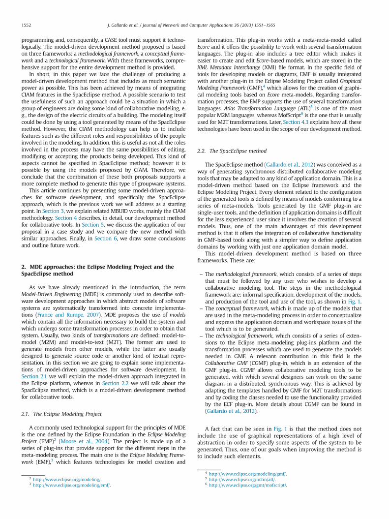
The methodological framework, which consists of a series of stepsthat must be followed by any user who wishes to develop acollaborative modeling tool. The steps in the methodologicalframework are: informal specification, development of the models,and production of the tool and use of the tool, as shown in Fig. 1.–
The conceptual framework, which is made up of the models thatare used in the meta-modeling process in order to conceptualizeand express the application domain and workspace issues of thetool which is to be generated.–
The technological framework, which consists of a series of exten-sions to the Eclipse meta-modeling plug-ins platform and thetransformation processes which are used to generate the modelsneeded in GMF. A relevant contribution in this field is theCollaborative GMF (CGMF) plug-in, which is an extension of theGMF plug-in. CGMF allows collaborative modeling tools to begenerated, with which several designers can work on the samediagram in a distributed, synchronous way. This is achieved byadapting the templates handled by GMF for M2T transformationsand by coding the classes needed to use the functionality providedby the ECF plug-in. More details about CGMF can be found in(Gallardo et al., 2012).A fact that can be seen in Fig. 1 is that the method does notinclude the use of graphical representations of a high level ofabstraction in order to specify some aspects of the system to begenerated. Thus, one of our goals when improving the method isto include such elements.
4 http://www.eclipse.org/modeling/gmf/.5 http://www.eclipse.org/m2m/atl/.6 http://www.eclipse.org/gmt/mofscript/.
Fig. 1. Outline of the SpacEclipse method.
J. Gallardo et al. / Journal of Network and Computer Applications 36 (2013) 1551–1565 1553
3. MBUID approaches: the CIAM methodology
The principles of MDE have been applied in the Human–Computer Interaction (HCI) area mainly in the development of userinterfaces (UI) (Vanderdonckt, 2008). This has given rise to the fieldof Model-Based User Interface Development (MBUID) (Sousa et al.,2007). In this field, the use of models is proposed in order to identify,organize and reflect on the components and behavior of an inter-active system. MBUID offers different levels of abstraction, with theuse of task models being its highest level (Vanderdonckt and Berquin,1999). Task models are logical descriptions of the tasks required bythe user to achieve their goals while interacting with the application(Dix, 1993; Paternò, 1999). The use of task models in the process ofdesigning and developing UIs allows more user-centered interactiveapplications to be built. In addition, they are a good communicationtool between the various people involved in the development of asystem (designers, engineers, users, experts in the domain, etc.)(Diaper and Stanton, 2004). There are several notations for declara-tive modeling of the interactive aspects of applications, but theConcurTaskTrees notation (CTT) (Paternò, 2004) is certainly the mostwidespread and accepted notation for task modeling.
Also, the modeling of group work has been of interest in the areasof HCI, as well as in the field of Software Engineering. Some of themost relevant contributions in HCI are the Group Task Analysis (GTA)framework (van Welie and van der Veer, 2003), the Collaborative
Usability Analysis (CUA) notation (Pinelle, 2004) and the MultipleAspect Based Task Analysis (MABTA) task analysis method (Lim, 2004).A more detailed review and comparative evaluation of differentnotations for interactive and collaborative modeling can be found inMolina et al. (2009b)).
With the aim of simplifying the task of developing collaborativesystems, some methodological approaches have been proposed forthe development of collaborative systems. AMENITIES is a metho-dology based on the use of behavior and task models for theanalysis, design and development of cooperative systems (Garridoet al., 2007). It is based on an ontological proposal for the specifica-tion of such systems. This proposal initially includes a domainontology for the CSCW domain and, later, application ontologies intwo levels. Thus, it is more centered in the modeling of the organ-ization and in concepts of a high level of abstraction among thoserelated with groupware systems.
On the other hand, TOUCHÉ (Penichet et al., 2010) is a processmodel and a methodology for the specification and design of group-ware applications. It proposes a method for requirements gathering,and it considers the specific characteristics and particularities ofthese systems from the beginning. It is based on a previous study ofCSCW systems that has resulted in a method for the classification ofsuch systems. Also, the study of specific concepts has resulted in aconceptual framework of terms and relationships upon which theprocess model relies.
J. Gallardo et al. / Journal of Network and Computer Applications 36 (2013) 1551–15651554
With the aim of solving the lack of approaches that linksinteractive and collaborative issues, the Collaborative InteractiveApplication Methodology (CIAM) methodology was proposed(Molina et al., 2009a). The objective of CIAM is to serve as a guidefor the designer when creating a conceptual specification of themain aspects that characterize the groupware systems and lead tothe design of the interaction that these systems support.
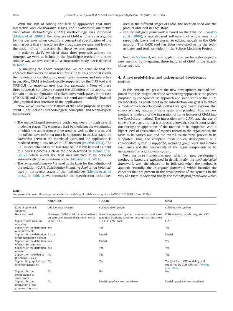
In order to clarify which of these three proposals address theconcepts we want to include in the SpacEclipse method in a moresuitable way, we have carried out a comparative study that is depictedin Table 1.
By analyzing the above comparison, we can conclude that theapproach that covers the most features is CIAM. This proposal allowsthe modeling of collaboration, users, tasks, sessions and interactiveissues. Also, CIAM is technologically supported by the CIAT tool andCIAT-GUI (for graphical user interface generation). None of thesethree proposals completely support the definition of the applicationdomain or the configuration of collaborative workspaces. In the caseof TOUCHE and CIAM, a final product is semi-automatically obtained(the graphical user interface of the application).
Now, we will explain the features of the CIAM proposal in greaterdetail. CIAM includes methodological, conceptual and technologicalframeworks:
–
TabCom
KsuN
SmSoSoSoSoSinSin
ScowSpg
The methodological framework guides engineers through severalmodeling stages. The engineers start by modeling the organizationin which the application will be used, as well as the process andthe collaborative tasks that must be supported. In the last stage, theinteraction between the individual users and the application ismodeled using a task model in CTT notation (Paternò, 2004). TheCTT model obtained in the last stage of CIAM can be used as inputto a MBUID process such as the one described in Molina et al.(2012), which allows the final user interface to be obtainedautomatically or semi-automatically (Meixner et al., 2011).
–
The conceptual framework is used as the basis for the definition ofthe notation (CIAN: Collaborative Interactive Application Notation)used in the several stages of the methodology (Molina et al., inpress). In Table 2, we summarize the specification techniquesle 1parison between three approaches for the modeling of collaborative systems (AMENITI
AMENITIES TOUCHE
ind of systems itpports
Collaborative systems Collaborative system
otations used Ontologies, COMO-UML (a notation basedon state and activity diagrams in UML)
A set of templates tgraphical diagrams
upport tools used forodeling
COMO-TOOL TOUCHE CASE Tool
upport for the definitionf requirements
Yes Yes
upport for the definitionf the application domain
Partial Partial
upport for the definitionf users, sessions, etc.
Yes Partial
upport for the definitionf tasks
Yes Yes
upport for modeling ofteractive issues
No Yes
upport for graphical userterface generation
No Yes
upport for thenfiguration oforkspaces
No No
upport for theroduction of theroupware system
No Partial (graphical u
used in the different stages of CIAM, the notation used and theproduct obtained in each stage.
–
The technological framework is based on the CIAT tool (Giraldoet al., 2008), a model-based software tool whose aim is tosupport designers and engineers in editing models in the CIANnotation. This CASE tool has been developed using the tech-nologies and tools provided in the Eclipse Modeling Project.Next, in Section 4, we will explain how we have developed anew method by integrating these features of CIAM in the SpacE-clipse method.
4. A new model-driven and task-oriented developmentmethod
In this section, we present the new development method pro-duced from the integration of the two starting approaches: the phasesproposed by the SpacEclipse approach and some steps of the CIAMmethodology. As pointed out in the introduction, our goal is to obtaina model-driven development method for groupware systems thatcovers as many features of those systems as possible. Thus, the newmethod is made up of the integration of some features of CIAM intothe SpacEclipse method. The integration with CIAM, and the use ofsome of the diagrams that it proposes, allows the specification carriedout during the application of the method to be supported with ahigher level of abstraction of aspects related to the organization, thetasks to be carried out, and the overall collaborative process to besupported. Thus, the complete model-driven development of acollaborative system is supported, including group work and interac-tion issues and the functionality of the main components to beincorporated in a groupware system.
Next, the three frameworks upon which our new developmentmethod is based are explained in detail: firstly, the methodologicalframework, with the phases to be followed when the method isapplied; secondly, the conceptual framework which includes theconcepts that are present in the development of the systems in theway of a meta-model; and finally, the technological frameworkwhich
ES, TOUCHE and CIAM).
CIAM
s Collaborative systems
o gather requirements and somebased on UML and CTT notations
CIAN notation, which integrates CTT
CIAT
Yes
Partial
Yes
Yes
Yes
Yes (thanks to CTT modeling andsupported by CIAT-GUI tool) (Molinaet al., 2012)No
ser interface) Partial (graphical user interface)
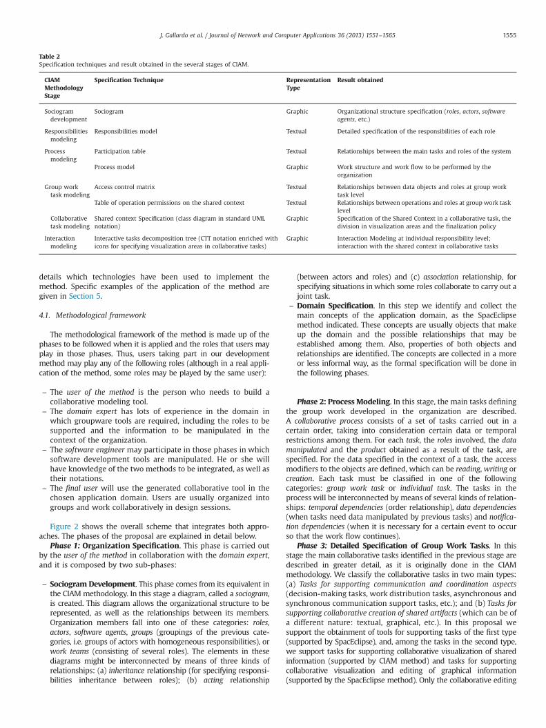
Table 2Specification techniques and result obtained in the several stages of CIAM.
CIAMMethodologyStage
Specification Technique RepresentationType
Result obtained
Sociogramdevelopment
Sociogram Graphic Organizational structure specification (roles, actors, softwareagents, etc.)
Responsibilitiesmodeling
Responsibilities model Textual Detailed specification of the responsibilities of each role
Processmodeling
Participation table Textual Relationships between the main tasks and roles of the system
Process model Graphic Work structure and work flow to be performed by theorganization
Group worktask modeling
Access control matrix Textual Relationships between data objects and roles at group worktask level
Table of operation permissions on the shared context Textual Relationships between operations and roles at group work tasklevel
Collaborativetask modeling
Shared context Specification (class diagram in standard UMLnotation)
Graphic Specification of the Shared Context in a collaborative task, thedivision in visualization areas and the finalization policy
Interactionmodeling
Interactive tasks decomposition tree (CTT notation enriched withicons for specifying visualization areas in collaborative tasks)
Graphic Interaction Modeling at individual responsibility level;interaction with the shared context in collaborative tasks
J. Gallardo et al. / Journal of Network and Computer Applications 36 (2013) 1551–1565 1555
details which technologies have been used to implement themethod. Specific examples of the application of the method aregiven in Section 5.
4.1. Methodological framework
The methodological framework of the method is made up of thephases to be followed when it is applied and the roles that users mayplay in those phases. Thus, users taking part in our developmentmethod may play any of the following roles (although in a real appli-cation of the method, some roles may be played by the same user):
–
The user of the method is the person who needs to build acollaborative modeling tool.–
The domain expert has lots of experience in the domain inwhich groupware tools are required, including the roles to besupported and the information to be manipulated in thecontext of the organization.–
The software engineer may participate in those phases in whichsoftware development tools are manipulated. He or she willhave knowledge of the two methods to be integrated, as well astheir notations.–
The final user will use the generated collaborative tool in thechosen application domain. Users are usually organized intogroups and work collaboratively in design sessions.Figure 2 shows the overall scheme that integrates both appro-aches. The phases of the proposal are explained in detail below.
Phase 1: Organization Specification. This phase is carried outby the user of the method in collaboration with the domain expert,and it is composed by two sub-phases:
–
Sociogram Development. This phase comes from its equivalent inthe CIAMmethodology. In this stage a diagram, called a sociogram,is created. This diagram allows the organizational structure to berepresented, as well as the relationships between its members.Organization members fall into one of these categories: roles,actors, software agents, groups (groupings of the previous cate-gories, i.e. groups of actors with homogeneous responsibilities), orwork teams (consisting of several roles). The elements in thesediagrams might be interconnected by means of three kinds ofrelationships: (a) inheritance relationship (for specifying responsi-bilities inheritance between roles); (b) acting relationship(between actors and roles) and (c) association relationship, forspecifying situations inwhich some roles collaborate to carry out ajoint task.
–
Domain Specification. In this step we identify and collect themain concepts of the application domain, as the SpacEclipsemethod indicated. These concepts are usually objects that makeup the domain and the possible relationships that may beestablished among them. Also, properties of both objects andrelationships are identified. The concepts are collected in a moreor less informal way, as the formal specification will be done inthe following phases.Phase 2: Process Modeling. In this stage, the main tasks definingthe group work developed in the organization are described.A collaborative process consists of a set of tasks carried out in acertain order, taking into consideration certain data or temporalrestrictions among them. For each task, the roles involved, the datamanipulated and the product obtained as a result of the task, arespecified. For the data specified in the context of a task, the accessmodifiers to the objects are defined, which can be reading, writing orcreation. Each task must be classified in one of the followingcategories: group work task or individual task. The tasks in theprocess will be interconnected by means of several kinds of relation-ships: temporal dependencies (order relationship), data dependencies(when tasks need data manipulated by previous tasks) and notifica-tion dependencies (when it is necessary for a certain event to occurso that the work flow continues).
Phase 3: Detailed Specification of Group Work Tasks. In thisstage the main collaborative tasks identified in the previous stage aredescribed in greater detail, as it is originally done in the CIAMmethodology. We classify the collaborative tasks in two main types:(a) Tasks for supporting communication and coordination aspects(decision-making tasks, work distribution tasks, asynchronous andsynchronous communication support tasks, etc.); and (b) Tasks forsupporting collaborative creation of shared artifacts (which can be ofa different nature: textual, graphical, etc.). In this proposal wesupport the obtainment of tools for supporting tasks of the first type(supported by SpacEclipse), and, among the tasks in the second type,we support tasks for supporting collaborative visualization of sharedinformation (supported by CIAM method) and tasks for supportingcollaborative visualization and editing of graphical information(supported by the SpacEclipse method). Only the collaborative editing
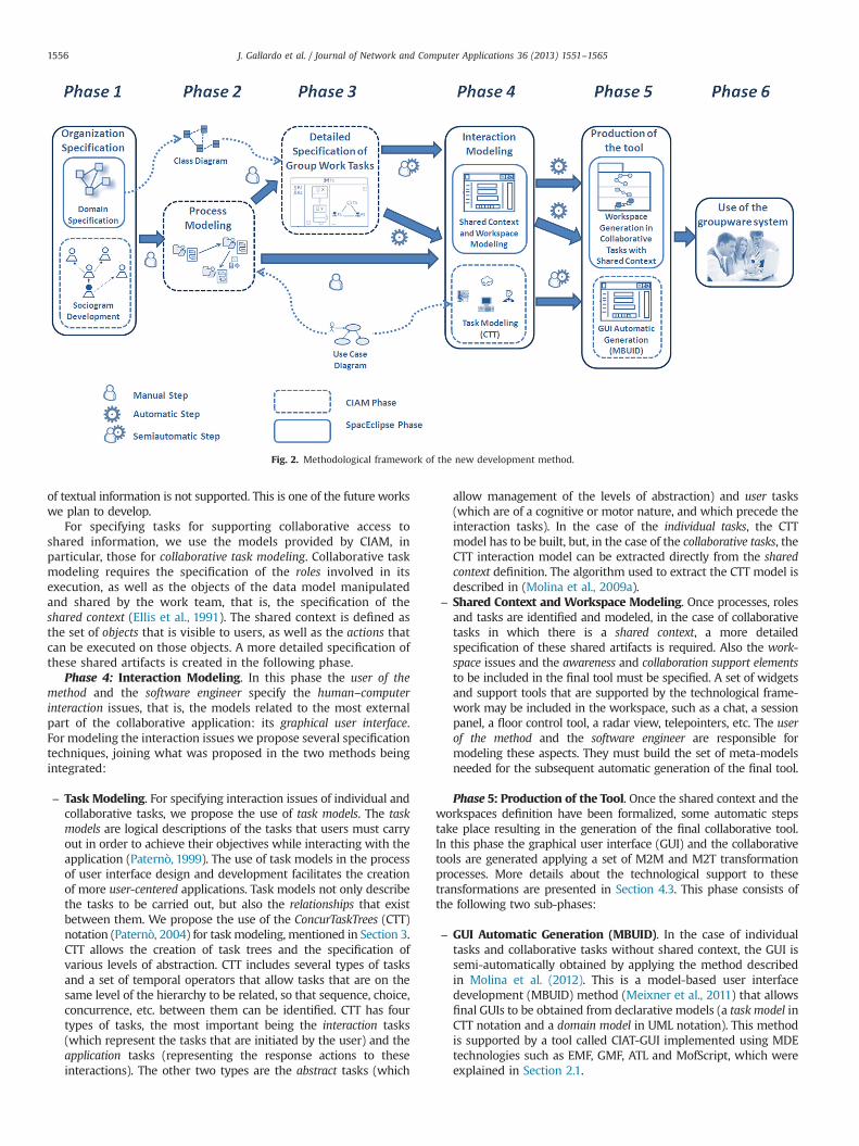
Fig. 2. Methodological framework of the new development method.
J. Gallardo et al. / Journal of Network and Computer Applications 36 (2013) 1551–15651556
of textual information is not supported. This is one of the future workswe plan to develop.
For specifying tasks for supporting collaborative access toshared information, we use the models provided by CIAM, inparticular, those for collaborative task modeling. Collaborative taskmodeling requires the specification of the roles involved in itsexecution, as well as the objects of the data model manipulatedand shared by the work team, that is, the specification of theshared context (Ellis et al., 1991). The shared context is defined asthe set of objects that is visible to users, as well as the actions thatcan be executed on those objects. A more detailed specification ofthese shared artifacts is created in the following phase.
Phase 4: Interaction Modeling. In this phase the user of themethod and the software engineer specify the human–computerinteraction issues, that is, the models related to the most externalpart of the collaborative application: its graphical user interface.For modeling the interaction issues we propose several specificationtechniques, joining what was proposed in the two methods beingintegrated:
–
Task Modeling. For specifying interaction issues of individual andcollaborative tasks, we propose the use of task models. The taskmodels are logical descriptions of the tasks that users must carryout in order to achieve their objectives while interacting with theapplication (Paternò, 1999). The use of task models in the processof user interface design and development facilitates the creationof more user-centered applications. Task models not only describethe tasks to be carried out, but also the relationships that existbetween them. We propose the use of the ConcurTaskTrees (CTT)notation (Paternò, 2004) for task modeling, mentioned in Section 3.CTT allows the creation of task trees and the specification ofvarious levels of abstraction. CTT includes several types of tasksand a set of temporal operators that allow tasks that are on thesame level of the hierarchy to be related, so that sequence, choice,concurrence, etc. between them can be identified. CTT has fourtypes of tasks, the most important being the interaction tasks(which represent the tasks that are initiated by the user) and theapplication tasks (representing the response actions to theseinteractions). The other two types are the abstract tasks (whichallow management of the levels of abstraction) and user tasks(which are of a cognitive or motor nature, and which precede theinteraction tasks). In the case of the individual tasks, the CTTmodel has to be built, but, in the case of the collaborative tasks, theCTT interaction model can be extracted directly from the sharedcontext definition. The algorithm used to extract the CTT model isdescribed in (Molina et al., 2009a).
–
Shared Context and Workspace Modeling. Once processes, rolesand tasks are identified and modeled, in the case of collaborativetasks in which there is a shared context, a more detailedspecification of these shared artifacts is required. Also the work-space issues and the awareness and collaboration support elementsto be included in the final tool must be specified. A set of widgetsand support tools that are supported by the technological frame-work may be included in the workspace, such as a chat, a sessionpanel, a floor control tool, a radar view, telepointers, etc. The userof the method and the software engineer are responsible formodeling these aspects. They must build the set of meta-modelsneeded for the subsequent automatic generation of the final tool.Phase 5: Production of the Tool. Once the shared context and theworkspaces definition have been formalized, some automatic stepstake place resulting in the generation of the final collaborative tool.In this phase the graphical user interface (GUI) and the collaborativetools are generated applying a set of M2M and M2T transformationprocesses. More details about the technological support to thesetransformations are presented in Section 4.3. This phase consists ofthe following two sub-phases:
–
GUI Automatic Generation (MBUID). In the case of individualtasks and collaborative tasks without shared context, the GUI issemi-automatically obtained by applying the method describedin Molina et al. (2012). This is a model-based user interfacedevelopment (MBUID) method (Meixner et al., 2011) that allowsfinal GUIs to be obtained from declarative models (a task model inCTT notation and a domain model in UML notation). This methodis supported by a tool called CIAT-GUI implemented using MDEtechnologies such as EMF, GMF, ATL and MofScript, which wereexplained in Section 2.1.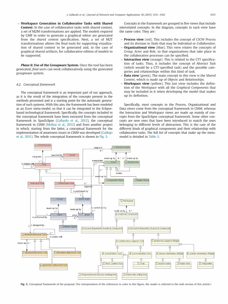
J. Gallardo et al. / Journal of Network and Computer Applications 36 (2013) 1551–1565 1557
–
Workspace Generation in Collaborative Tasks with SharedContext. In the case of collaborative tasks with shared context,a set of M2M transformations are applied. The models requiredby GMF in order to generate a graphical editor are generatedfrom the shared context specification. Next, a set of M2Ttransformations allows the final tools for supporting visualiza-tion of shared context to be generated and, in the case ofgraphical shared artifacts, for collaborative edition of models tobe supported.Phase 6: Use of the Groupware System. Once the tool has beengenerated, final users can work collaboratively using the generatedgroupware system.
4.2. Conceptual framework
The conceptual framework is an important part of our approach,as it is the result of the integration of the concepts present in themethods presented and is a starting point for the automatic genera-tion of such systems. With this aim, the framework has been modeledas an Ecore meta-model, so that it can be integrated in the Eclipse-based technological framework. Specifically, the concepts included inthe conceptual framework have been extracted from the conceptualframework in SpacEclipse (Gallardo et al., 2012), the conceptualframework in CIAM (Molina et al., 2012) and from another projectin which, starting from the latter, a conceptual framework for theimplementation of awareness issues in CIAM was developed (Gallegoet al., 2011). The whole conceptual framework is shown in Fig. 3.
Fig. 3. Conceptual framework of the proposal. (For interpretation of the references
Concepts in the framework are grouped in five views that includeinterrelated concepts. In the diagram, concepts in each view havethe same color. They are:
–
to c
Process view (red). This includes the concept of CSCW Processand its division in Tasks that may be Individual or Collaborative.
–
Organizational view (blue). This view relates the concepts ofGroup, Actor and Role, so that organizations that take place inthe collaborative processes can be specified.–
Interaction view (orange). This is related to the CTT specifica-tion of tasks. Thus, it includes the concept of Abstract Task(which would be a CTT-specified task) and the possible cate-gories and relationships within this kind of task.–
Data view (green). The main concept in this view is the SharedContext, which is made up of Objects and Relationships.–
Workspace view (yellow). This last view includes the defini-tion of the Workspace with all the Graphical Components thatmay be included in it when developing the model that makesup its definition.Specifically, most concepts in the Process, Organizational andData views come from the conceptual framework in CIAM, whereasthe Interaction and Workspace views are made up mainly of con-cepts from the SpacEclipse conceptual framework. Some other con-cepts are new ones that have been introduced to match the onesbelonging to different levels of abstraction. This is the case of thedifferent kinds of graphical components and their relationship withcollaborative tasks. The full list of concepts that make up the meta-model is detailed in Table 3.
olor in this figure, the reader is referred to the web version of this article.)
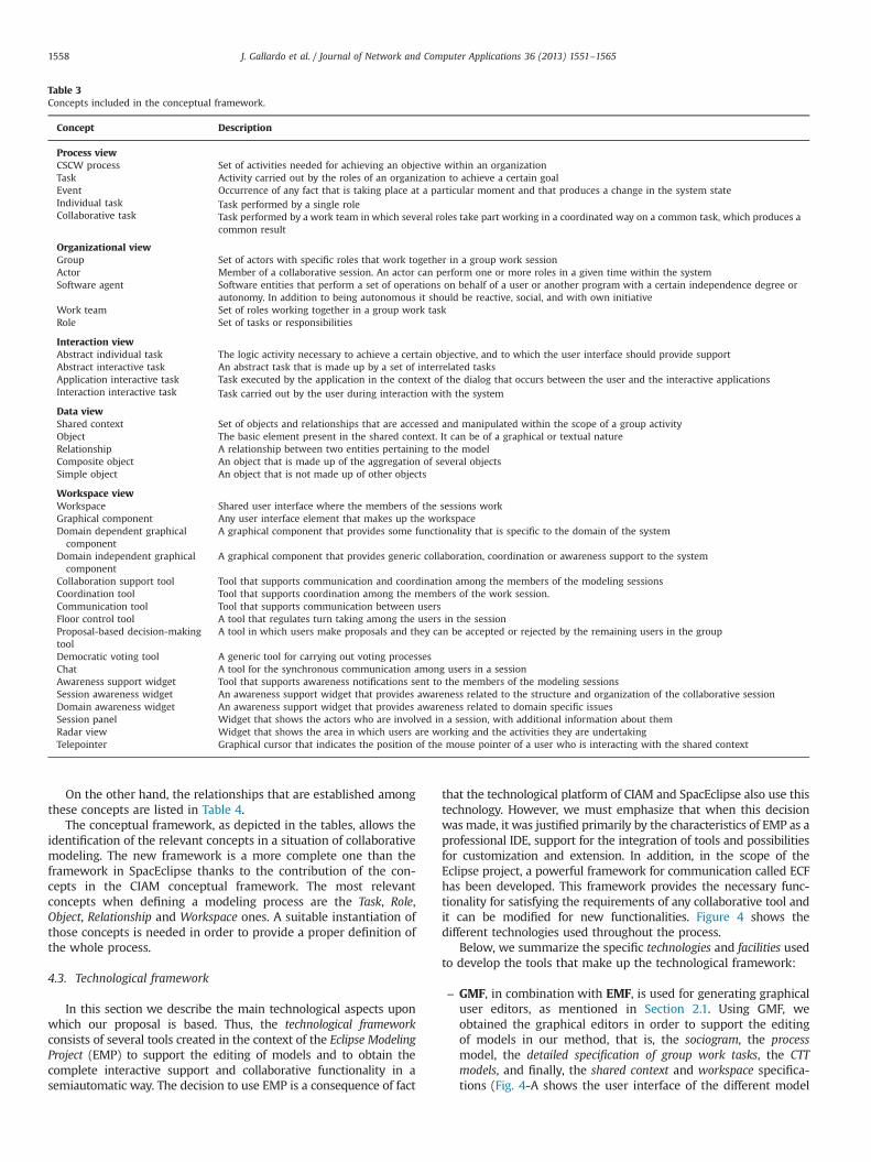
Table 3Concepts included in the conceptual framework.
Concept Description
Process viewCSCW process Set of activities needed for achieving an objective within an organizationTask Activity carried out by the roles of an organization to achieve a certain goalEvent Occurrence of any fact that is taking place at a particular moment and that produces a change in the system stateIndividual task Task performed by a single roleCollaborative task Task performed by a work team in which several roles take part working in a coordinated way on a common task, which produces a
common result
Organizational viewGroup Set of actors with specific roles that work together in a group work sessionActor Member of a collaborative session. An actor can perform one or more roles in a given time within the systemSoftware agent Software entities that perform a set of operations on behalf of a user or another program with a certain independence degree or
autonomy. In addition to being autonomous it should be reactive, social, and with own initiativeWork team Set of roles working together in a group work taskRole Set of tasks or responsibilities
Interaction viewAbstract individual task The logic activity necessary to achieve a certain objective, and to which the user interface should provide supportAbstract interactive task An abstract task that is made up by a set of interrelated tasksApplication interactive task Task executed by the application in the context of the dialog that occurs between the user and the interactive applicationsInteraction interactive task Task carried out by the user during interaction with the system
Data viewShared context Set of objects and relationships that are accessed and manipulated within the scope of a group activityObject The basic element present in the shared context. It can be of a graphical or textual natureRelationship A relationship between two entities pertaining to the modelComposite object An object that is made up of the aggregation of several objectsSimple object An object that is not made up of other objects
Workspace viewWorkspace Shared user interface where the members of the sessions workGraphical component Any user interface element that makes up the workspaceDomain dependent graphicalcomponent
A graphical component that provides some functionality that is specific to the domain of the system
Domain independent graphicalcomponent
A graphical component that provides generic collaboration, coordination or awareness support to the system
Collaboration support tool Tool that supports communication and coordination among the members of the modeling sessionsCoordination tool Tool that supports coordination among the members of the work session.Communication tool Tool that supports communication between usersFloor control tool A tool that regulates turn taking among the users in the sessionProposal-based decision-makingtool
A tool in which users make proposals and they can be accepted or rejected by the remaining users in the group
Democratic voting tool A generic tool for carrying out voting processesChat A tool for the synchronous communication among users in a sessionAwareness support widget Tool that supports awareness notifications sent to the members of the modeling sessionsSession awareness widget An awareness support widget that provides awareness related to the structure and organization of the collaborative sessionDomain awareness widget An awareness support widget that provides awareness related to domain specific issuesSession panel Widget that shows the actors who are involved in a session, with additional information about themRadar view Widget that shows the area in which users are working and the activities they are undertakingTelepointer Graphical cursor that indicates the position of the mouse pointer of a user who is interacting with the shared context
J. Gallardo et al. / Journal of Network and Computer Applications 36 (2013) 1551–15651558
On the other hand, the relationships that are established amongthese concepts are listed in Table 4.
The conceptual framework, as depicted in the tables, allows theidentification of the relevant concepts in a situation of collaborativemodeling. The new framework is a more complete one than theframework in SpacEclipse thanks to the contribution of the con-cepts in the CIAM conceptual framework. The most relevantconcepts when defining a modeling process are the Task, Role,Object, Relationship and Workspace ones. A suitable instantiation ofthose concepts is needed in order to provide a proper definition ofthe whole process.
4.3. Technological framework
In this section we describe the main technological aspects uponwhich our proposal is based. Thus, the technological frameworkconsists of several tools created in the context of the Eclipse ModelingProject (EMP) to support the editing of models and to obtain thecomplete interactive support and collaborative functionality in asemiautomatic way. The decision to use EMP is a consequence of fact
that the technological platform of CIAM and SpacEclipse also use thistechnology. However, we must emphasize that when this decisionwas made, it was justified primarily by the characteristics of EMP as aprofessional IDE, support for the integration of tools and possibilitiesfor customization and extension. In addition, in the scope of theEclipse project, a powerful framework for communication called ECFhas been developed. This framework provides the necessary func-tionality for satisfying the requirements of any collaborative tool andit can be modified for new functionalities. Figure 4 shows thedifferent technologies used throughout the process.
Below, we summarize the specific technologies and facilities usedto develop the tools that make up the technological framework:
–
GMF, in combination with EMF, is used for generating graphicaluser editors, as mentioned in Section 2.1. Using GMF, weobtained the graphical editors in order to support the editingof models in our method, that is, the sociogram, the processmodel, the detailed specification of group work tasks, the CTTmodels, and finally, the shared context and workspace specifica-tions (Fig. 4-A shows the user interface of the different model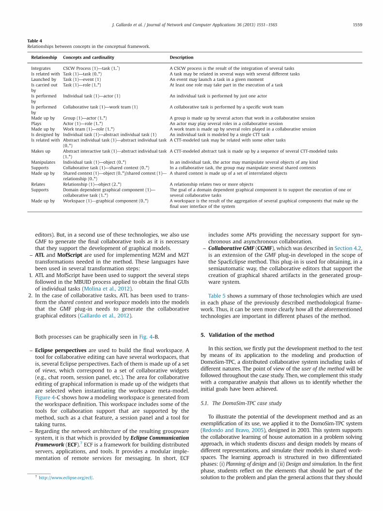
Table 4Relationships between concepts in the conceptual framework.
Relationship Concepts and cardinality Description
Integrates CSCW Process (1)—task (1..n
) A CSCW process is the result of the integration of several tasksIs related with Task (1)—task (0..n) A task may be related in several ways with several different tasksLaunched by Task (1)—event (1) An event may launch a task in a given momentIs carried outby
Task (1)—role (1..n) At least one role may take part in the execution of a task
Is performedby
Individual task (1)—actor (1) An individual task is performed by just one actor
Is performedby
Collaborative task (1)—work team (1) A collaborative task is performed by a specific work team
Made up by Group (1)—actor (1..n) A group is made up by several actors that work in a collaborative sessionPlays Actor (1)—role (1..n) An actor may play several roles in a collaborative sessionMade up by Work team (1)—role (1..n) A work team is made up by several roles played in a collaborative sessionIs designed by Individual task (1)—abstract individual task (1) An individual task is modeled by a single CTT taskIs related with Abstract individual task (1)—abstract individual task
(0..n)A CTT-modeled task may be related with some other tasks
Makes up Abstract interactive task (1)—abstract individual task(1..n)
A CTT-modeled abstract task is made up by a sequence of several CTT-modeled tasks
Manipulates Individual task (1)—object (0..n) In an individual task, the actor may manipulate several objects of any kindSupports Collaborative task (1)—shared context (0..n) In a collaborative task, the group may manipulate several shared contextsMade up by Shared context (1)—object (0..n)/shared context (1)—
relationship (0..n)A shared context is made up of a set of interrelated objects
Relates Relationship (1)—object (2..n) A relationship relates two or more objectsSupports Domain dependent graphical component (1)—
collaborative task (1..n)The goal of a domain dependent graphical component is to support the execution of one orseveral collaborative tasks
Made up by Workspace (1)—graphical component (0..n) A workspace is the result of the aggregation of several graphical components that make up thefinal user interface of the system
J. Gallardo et al. / Journal of Network and Computer Applications 36 (2013) 1551–1565 1559
editors). But, in a second use of these technologies, we also useGMF to generate the final collaborative tools as it is necessarythat they support the development of graphical models.
–
ATL and MofScript are used for implementing M2M and M2Ttransformations needed in the method. These languages havebeen used in several transformation steps:1.
ATL and MofScript have been used to support the several stepsfollowed in the MBUID process applied to obtain the final GUIsof individual tasks (Molina et al., 2012).2.
In the case of collaborative tasks, ATL has been used to trans-form the shared context and workspace models into the modelsthat the GMF plug-in needs to generate the collaborativegraphical editors (Gallardo et al., 2012).Both processes can be graphically seen in Fig. 4-B.
–
Eclipse perspectives are used to build the final workspace. Atool for collaborative editing can have several workspaces, thatis, several Eclipse perspectives. Each of them is made up of a setof views, which correspond to a set of collaborative widgets(e.g., chat room, session panel, etc.). The area for collaborativeediting of graphical information is made up of the widgets thatare selected when instantiating the workspace meta-model.Figure 4-C shows how a modeling workspace is generated fromthe workspace definition. This workspace includes some of thetools for collaboration support that are supported by themethod, such as a chat feature, a session panel and a tool fortaking turns.–
Regarding the network architecture of the resulting groupwaresystem, it is that which is provided by Eclipse CommunicationFramework (ECF).7 ECF is a framework for building distributedservers, applications, and tools. It provides a modular imple-mentation of remote services for messaging. In short, ECF7 http://www.eclipse.org/ecf/.
includes some APIs providing the necessary support for syn-chronous and asynchronous collaboration.
–
Collaborative GMF (CGMF), which was described in Section 4.2,is an extension of the GMF plug-in developed in the scope ofthe SpacEclipse method. This plug-in is used for obtaining, in asemiautomatic way, the collaborative editors that support thecreation of graphical shared artifacts in the generated group-ware system.Table 5 shows a summary of those technologies which are usedin each phase of the previously described methodological frame-work. Thus, it can be seen more clearly how all the aforementionedtechnologies are important in different phases of the method.
5. Validation of the method
In this section, we firstly put the development method to the testby means of its application to the modeling and production ofDomoSim-TPC, a distributed collaborative system including tasks ofdifferent natures. The point of view of the user of the method will befollowed throughout the case study. Then, we complement this studywith a comparative analysis that allows us to identify whether theinitial goals have been achieved.
5.1. The DomoSim-TPC case study
To illustrate the potential of the development method and as anexemplification of its use, we applied it to the DomoSim-TPC system(Redondo and Bravo, 2005), designed in 2003. This system supportsthe collaborative learning of house automation in a problem solvingapproach, in which students discuss and design models by means ofdifferent representations, and simulate their models in shared work-spaces. The learning approach is structured in two differentiatedphases: (i) Planning of design and (ii) Design and simulation. In the firstphase, students reflect on the elements that should be part of thesolution to the problem and plan the general actions that they should
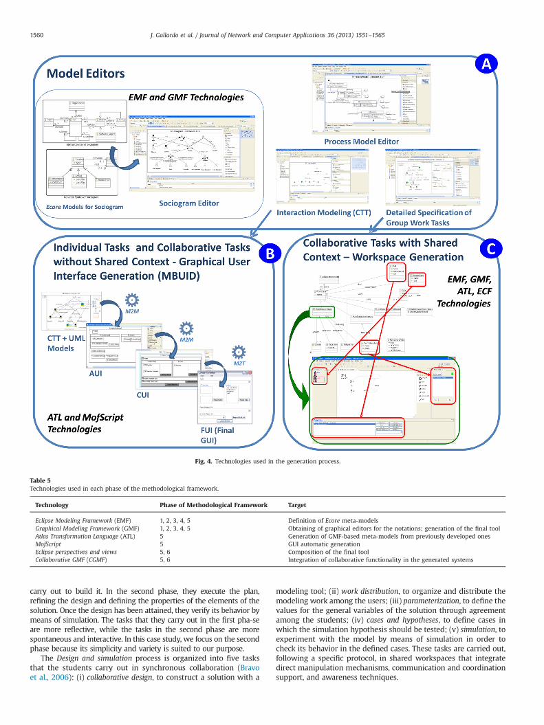
Fig. 4. Technologies used in the generation process.
Table 5Technologies used in each phase of the methodological framework.
Technology Phase of Methodological Framework Target
Eclipse Modeling Framework (EMF) 1, 2, 3, 4, 5 Definition of Ecore meta-modelsGraphical Modeling Framework (GMF) 1, 2, 3, 4, 5 Obtaining of graphical editors for the notations; generation of the final toolAtlas Transformation Language (ATL) 5 Generation of GMF-based meta-models from previously developed onesMofScript 5 GUI automatic generationEclipse perspectives and views 5, 6 Composition of the final toolCollaborative GMF (CGMF) 5, 6 Integration of collaborative functionality in the generated systems
J. Gallardo et al. / Journal of Network and Computer Applications 36 (2013) 1551–15651560
carry out to build it. In the second phase, they execute the plan,refining the design and defining the properties of the elements of thesolution. Once the design has been attained, they verify its behavior bymeans of simulation. The tasks that they carry out in the first pha-seare more reflective, while the tasks in the second phase are morespontaneous and interactive. In this case study, we focus on the secondphase because its simplicity and variety is suited to our purpose.
The Design and simulation process is organized into five tasksthat the students carry out in synchronous collaboration (Bravoet al., 2006): (i) collaborative design, to construct a solution with a
modeling tool; (ii) work distribution, to organize and distribute themodeling work among the users; (iii) parameterization, to define thevalues for the general variables of the solution through agreementamong the students; (iv) cases and hypotheses, to define cases inwhich the simulation hypothesis should be tested; (v) simulation, toexperiment with the model by means of simulation in order tocheck its behavior in the defined cases. These tasks are carried out,following a specific protocol, in shared workspaces that integratedirect manipulation mechanisms, communication and coordinationsupport, and awareness techniques.
J. Gallardo et al. / Journal of Network and Computer Applications 36 (2013) 1551–1565 1561
The original system was entirely developed in Java following aclient/server model, and the collaboration services were implemen-ted using sockets on centralized-hybrid architecture. Our aim is todevelop a new version of the system in a re-engineering processusing the development method proposed in this article. Next, thedifferent phases of the method are applied.
Fig. 6. DomoSim-TPC
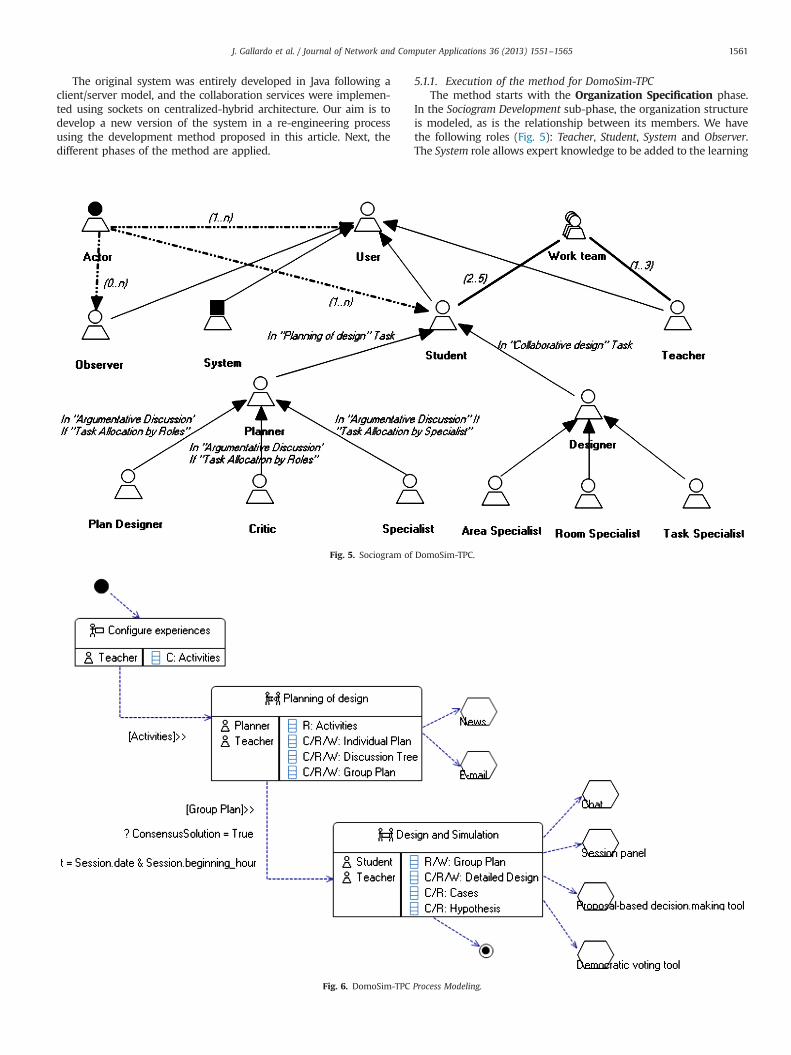
Fig. 5. Sociogram of
5.1.1. Execution of the method for DomoSim-TPCThe method starts with the Organization Specification phase.
In the Sociogram Development sub-phase, the organization structureis modeled, as is the relationship between its members. We havethe following roles (Fig. 5): Teacher, Student, System and Observer.The System role allows expert knowledge to be added to the learning
Process Modeling.
DomoSim-TPC.
J. Gallardo et al. / Journal of Network and Computer Applications 36 (2013) 1551–15651562
process. Two specialized students called Planner and Designer whotake part in the two main tasks are identified. The inheritance rela-tionships (continuous-lined arrows) can be enriched with the def-inition of conditions. For example, we show that a Student can bespecialized in the Designer role in the context of the Design Task.The Planner role has several sub-roles (Plan Designer, Critic orSpecialist). A Planner can play any of them depending on the TaskAllocation chosen for the activity. Once the inheritance relationshipsbetween roles are established, the actor-role relationships (broken-lined arrows) are added for the main roles in the diagram in order toexpress cardinality (minimum and maximum). The diagram alsoallows one to show the relationships among roles that can, at acertain moment, work together. These relationships are expressedby means of association relationships (thick lines). The sociogramshows that the Student and Teacher roles are associated, creating awork team. This indicates that there are tasks in which both rolestake part, each one with its respective responsibilities.
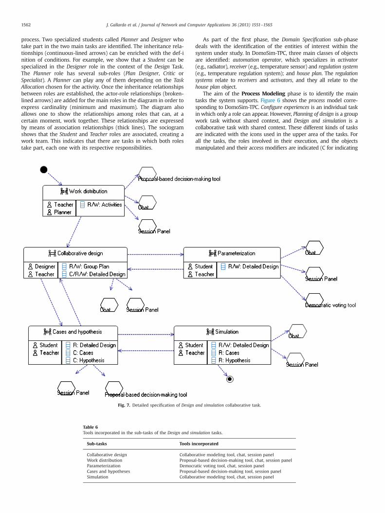
Fig. 7. Detailed specification of Design
Table 6Tools incorporated in the sub-tasks of the Design and sim
Sub-tasks Tools in
Collaborative design CollaboWork distribution ProposaParameterization DemocrCases and hypotheses ProposaSimulation Collabo
As part of the first phase, the Domain Specification sub-phasedeals with the identification of the entities of interest within thesystem under study. In DomoSim-TPC, three main classes of objectsare identified: automation operator, which specializes in activator(e.g., radiator), receiver (e.g., temperature sensor) and regulation system(e.g., temperature regulation system); and house plan. The regulationsystems relate to receivers and activators, and they all relate to thehouse plan object.
The aim of the Process Modeling phase is to identify the maintasks the system supports. Figure 6 shows the process model corre-sponding to DomoSim-TPC. Configure experiences is an individual taskin which only a role can appear. However, Planning of design is a groupwork task without shared context, and Design and simulation is acollaborative task with shared context. These different kinds of tasksare indicated with the icons used in the upper area of the tasks. Forall the tasks, the roles involved in their execution, and the objectsmanipulated and their access modifiers are indicated (C for indicating
and simulation collaborative task.
ulation tasks.
corporated
rative modeling tool, chat, session panell-based decision-making tool, chat, session panelatic voting tool, chat, session panell-based decision-making tool, session panelrative modeling tool, chat, session panel
J. Gallardo et al. / Journal of Network and Computer Applications 36 (2013) 1551–1565 1563
creation of objects, R for reading and W for writing). In addition, eachtask can specify the domain independent support tools and widgets,which implement well-known patterns or interaction protocols. Theprocess model also includes temporal and data dependencies betweenthe tasks Configure experiences and Planning of design, indicating thatthe Activities data is transferred and the relationship between the tasksis sequential (»). Between the tasks Planning of design and Design andsimulation, a time dependence and a condition that must be checkedcan be found.
In the third phase of the method, Detailed Specification of GroupWork Tasks, the tasks identified in the previous phase are decom-posed. As mentioned above, we focus on the Design and simulationworkspace. Thus, the Design and simulation task is made up of theWork distribution, Collaborative design, Parameterization, Cases andhypotheses and Simulation sub-tasks (Fig. 7). The Collaborative designand Simulation sub-tasks are categorized as tasks for supportingcollaborative creation of shared artifacts, using a collaborative model-ing tool from the SpacEclipse method, and the remaining sub-tasksare for supporting communication and coordination aspects accordingto the sub-task categorization established. This categorization consti-tutes a key issue that conducts the specification and development ofthe sub-tasks. The following tools complete the collaboration supportof the sub-tasks: chat, session panel, democratic voting tool andproposal-based decision-making tool. Table 6 shows the tools availablein each sub-task. It is worth noting that the modeling tool includes afloor control mechanism and a radar view.
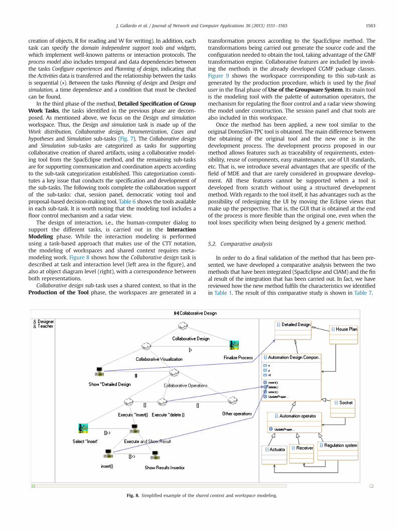
The design of interaction, i.e., the human-computer dialog tosupport the different tasks, is carried out in the InteractionModeling phase. While the interaction modeling is performedusing a task-based approach that makes use of the CTT notation,the modeling of workspaces and shared context requires meta-modeling work. Figure 8 shows how the Collaborative design task isdescribed at task and interaction level (left area in the figure), andalso at object diagram level (right), with a correspondence betweenboth representations.
Collaborative design sub-task uses a shared context, so that in theProduction of the Tool phase, the workspaces are generated in a
Fig. 8. Simplified example of the share
transformation process according to the SpacEclipse method. Thetransformations being carried out generate the source code and theconfiguration needed to obtain the tool, taking advantage of the GMFtransformation engine. Collaborative features are included by invok-ing the methods in the already developed CGMF package classes.Figure 9 shows the workspace corresponding to this sub-task asgenerated by the production procedure, which is used by the finaluser in the final phase of Use of the Groupware System. Its main toolis the modeling tool with the palette of automation operators, themechanism for regulating the floor control and a radar view showingthe model under construction. The session panel and chat tools arealso included in this workspace.
Once the method has been applied, a new tool similar to theoriginal DomoSim-TPC tool is obtained. The main difference betweenthe obtaining of the original tool and the new one is in thedevelopment process. The development process proposed in ourmethod allows features such as traceability of requirements, exten-sibility, reuse of components, easy maintenance, use of UI standards,etc. That is, we introduce several advantages that are specific of thefield of MDE and that are rarely considered in groupware develop-ment. All these features cannot be supported when a tool isdeveloped from scratch without using a structured developmentmethod. With regards to the tool itself, it has advantages such as thepossibility of redesigning the UI by moving the Eclipse views thatmake up the perspective. That is, the GUI that is obtained at the endof the process is more flexible than the original one, even when thetool loses specificity when being designed by a generic method.
5.2. Comparative analysis
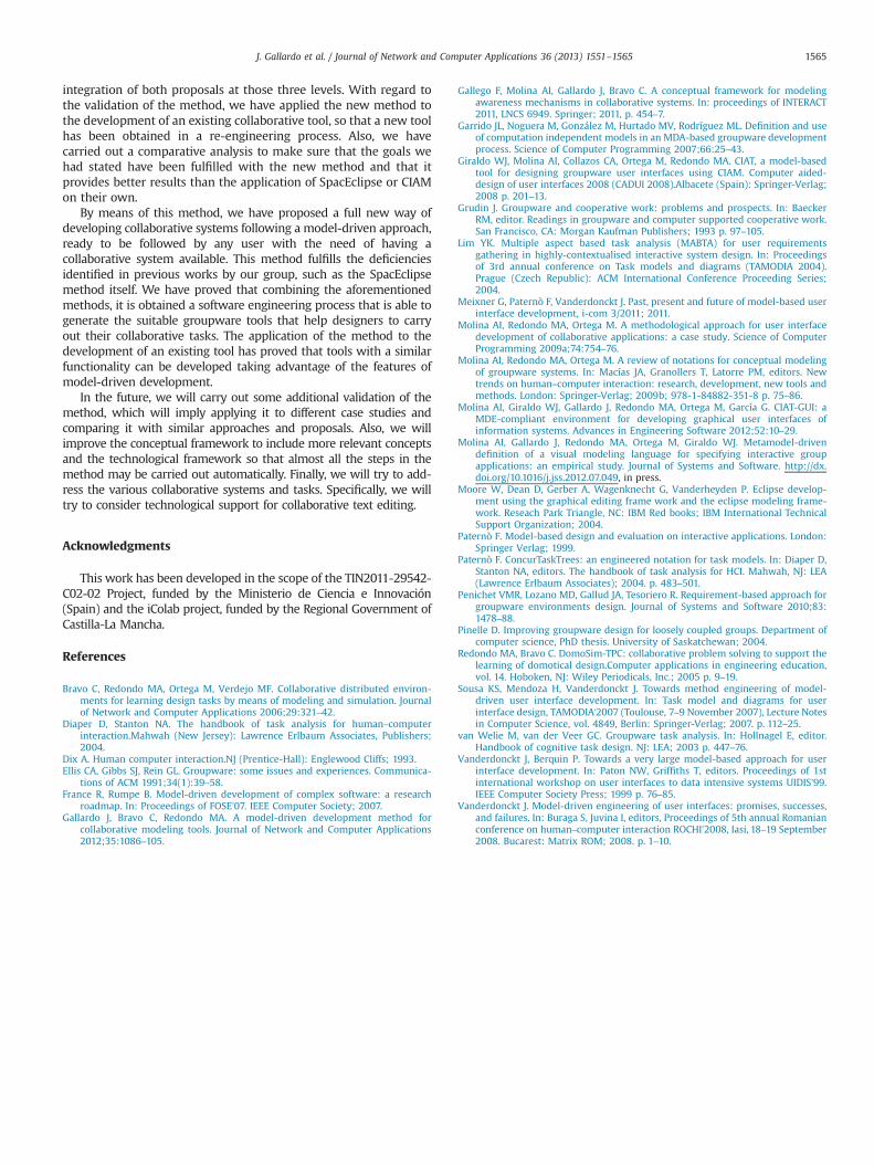
In order to do a final validation of the method that has been pre-sented, we have developed a comparative analysis between the twomethods that have been integrated (SpacEclipse and CIAM) and the final result of the integration that has been carried out. In fact, we havereviewed how the newmethod fulfils the characteristics we identifiedin Table 1. The result of this comparative study is shown in Table 7.
d context and workspace modeling.
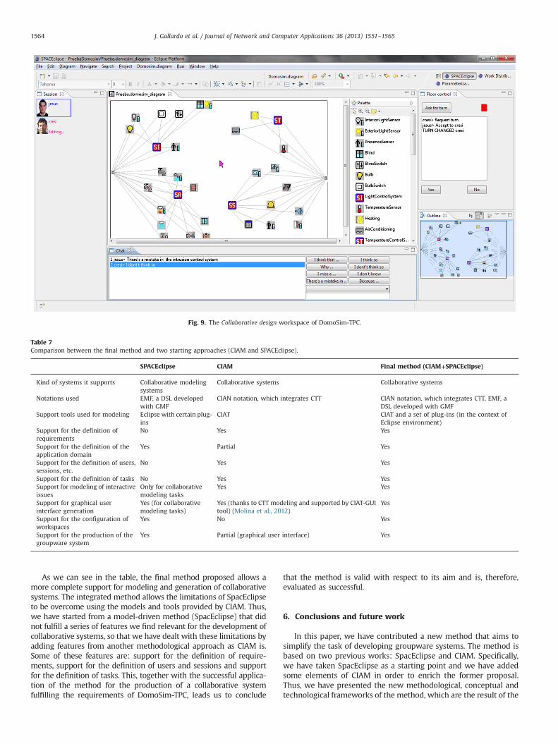
Table 7Comparison between the final method and two starting approaches (CIAM and SPACEclipse).
SPACEclipse CIAM Final method (CIAM+SPACEclipse)
Kind of systems it supports Collaborative modelingsystems
Collaborative systems Collaborative systems
Notations used EMF, a DSL developedwith GMF
CIAN notation, which integrates CTT CIAN notation, which integrates CTT, EMF, aDSL developed with GMF
Support tools used for modeling Eclipse with certain plug-ins
CIAT CIAT and a set of plug-ins (in the context ofEclipse environment)
Support for the definition ofrequirements
No Yes Yes
Support for the definition of theapplication domain
Yes Partial Yes
Support for the definition of users,sessions, etc.
No Yes Yes
Support for the definition of tasks No Yes YesSupport for modeling of interactiveissues
Only for collaborativemodeling tasks
Yes Yes
Support for graphical userinterface generation
Yes (for collaborativemodeling tasks)
Yes (thanks to CTT modeling and supported by CIAT-GUItool) (Molina et al., 2012)
Yes
Support for the configuration ofworkspaces
Yes No Yes
Support for the production of thegroupware system
Yes Partial (graphical user interface) Yes
Fig. 9. The Collaborative design workspace of DomoSim-TPC.
J. Gallardo et al. / Journal of Network and Computer Applications 36 (2013) 1551–15651564
As we can see in the table, the final method proposed allows amore complete support for modeling and generation of collaborativesystems. The integrated method allows the limitations of SpacEclipseto be overcome using the models and tools provided by CIAM. Thus,we have started from a model-driven method (SpacEclipse) that didnot fulfill a series of features we find relevant for the development ofcollaborative systems, so that we have dealt with these limitations byadding features from another methodological approach as CIAM is.Some of these features are: support for the definition of require-ments, support for the definition of users and sessions and supportfor the definition of tasks. This, together with the successful applica-tion of the method for the production of a collaborative systemfulfilling the requirements of DomoSim-TPC, leads us to conclude
that the method is valid with respect to its aim and is, therefore,evaluated as successful.
6. Conclusions and future work
In this paper, we have contributed a new method that aims tosimplify the task of developing groupware systems. The method isbased on two previous works: SpacEclipse and CIAM. Specifically,we have taken SpacEclipse as a starting point and we have addedsome elements of CIAM in order to enrich the former proposal.Thus, we have presented the new methodological, conceptual andtechnological frameworks of the method, which are the result of the
J. Gallardo et al. / Journal of Network and Computer Applications 36 (2013) 1551–1565 1565
integration of both proposals at those three levels. With regard tothe validation of the method, we have applied the new method tothe development of an existing collaborative tool, so that a new toolhas been obtained in a re-engineering process. Also, we havecarried out a comparative analysis to make sure that the goals wehad stated have been fulfilled with the new method and that itprovides better results than the application of SpacEclipse or CIAMon their own.
By means of this method, we have proposed a full new way ofdeveloping collaborative systems following a model-driven approach,ready to be followed by any user with the need of having acollaborative system available. This method fulfills the deficienciesidentified in previous works by our group, such as the SpacEclipsemethod itself. We have proved that combining the aforementionedmethods, it is obtained a software engineering process that is able togenerate the suitable groupware tools that help designers to carryout their collaborative tasks. The application of the method to thedevelopment of an existing tool has proved that tools with a similarfunctionality can be developed taking advantage of the features ofmodel-driven development.
In the future, we will carry out some additional validation of themethod, which will imply applying it to different case studies andcomparing it with similar approaches and proposals. Also, we willimprove the conceptual framework to include more relevant conceptsand the technological framework so that almost all the steps in themethod may be carried out automatically. Finally, we will try to add-ress the various collaborative systems and tasks. Specifically, we willtry to consider technological support for collaborative text editing.
Acknowledgments
This work has been developed in the scope of the TIN2011-29542-C02-02 Project, funded by the Ministerio de Ciencia e Innovación(Spain) and the iColab project, funded by the Regional Government ofCastilla-La Mancha.
References
Bravo C, Redondo MA, Ortega M, Verdejo MF. Collaborative distributed environ-ments for learning design tasks by means of modeling and simulation. Journalof Network and Computer Applications 2006;29:321–42.
Diaper D, Stanton NA. The handbook of task analysis for human–computerinteraction.Mahwah (New Jersey): Lawrence Erlbaum Associates, Publishers;2004.
Dix A. Human computer interaction.NJ (Prentice-Hall): Englewood Cliffs; 1993.Ellis CA, Gibbs SJ, Rein GL. Groupware: some issues and experiences. Communica-
tions of ACM 1991;34(1):39–58.France R, Rumpe B. Model-driven development of complex software: a research
roadmap. In: Proceedings of FOSE’07. IEEE Computer Society; 2007.Gallardo J, Bravo C, Redondo MA. A model-driven development method for
collaborative modeling tools. Journal of Network and Computer Applications2012;35:1086–105.
Gallego F, Molina AI, Gallardo J, Bravo C. A conceptual framework for modelingawareness mechanisms in collaborative systems. In: proceedings of INTERACT2011, LNCS 6949. Springer; 2011, p. 454–7.
Garrido JL, Noguera M, González M, Hurtado MV, Rodríguez ML. Definition and useof computation independent models in an MDA-based groupware developmentprocess. Science of Computer Programming 2007;66:25–43.
Giraldo WJ, Molina AI, Collazos CA, Ortega M, Redondo MA. CIAT, a model-basedtool for designing groupware user interfaces using CIAM. Computer aided-design of user interfaces 2008 (CADUI 2008).Albacete (Spain): Springer-Verlag;2008 p. 201–13.
Grudin J. Groupware and cooperative work: problems and prospects. In: BaeckerRM, editor. Readings in groupware and computer supported cooperative work.San Francisco, CA: Morgan Kaufman Publishers; 1993 p. 97–105.
Lim YK. Multiple aspect based task analysis (MABTA) for user requirementsgathering in highly-contextualised interactive system design. In: Proceedingsof 3rd annual conference on Task models and diagrams (TAMODIA 2004).Prague (Czech Republic): ACM International Conference Proceeding Series;2004.
Meixner G, Paternò F, Vanderdonckt J. Past, present and future of model-based userinterface development, i-com 3/2011; 2011.
Molina AI, Redondo MA, Ortega M. A methodological approach for user interfacedevelopment of collaborative applications: a case study. Science of ComputerProgramming 2009a;74:754–76.
Molina AI, Redondo MA, Ortega M. A review of notations for conceptual modelingof groupware systems. In: Macías JA, Granollers T, Latorre PM, editors. Newtrends on human–computer interaction: research, development, new tools andmethods. London: Springer-Verlag; 2009b; 978-1-84882-351-8 p. 75–86.
Molina AI, Giraldo WJ, Gallardo J, Redondo MA, Ortega M, García G. CIAT-GUI: aMDE-compliant environment for developing graphical user interfaces ofinformation systems. Advances in Engineering Software 2012;52:10–29.
Molina AI, Gallardo J, Redondo MA, Ortega M, Giraldo WJ. Metamodel-drivendefinition of a visual modeling language for specifying interactive groupapplications: an empirical study. Journal of Systems and Software. http://dx.doi.org/10.1016/j.jss.2012.07.049, in press.
Moore W, Dean D, Gerber A, Wagenknecht G, Vanderheyden P. Eclipse develop-ment using the graphical editing frame work and the eclipse modeling frame-work. Reseach Park Triangle, NC: IBM Red books; IBM International TechnicalSupport Organization; 2004.
Paternò F. Model-based design and evaluation on interactive applications. London:Springer Verlag; 1999.
Paternò F. ConcurTaskTrees: an engineered notation for task models. In: Diaper D,Stanton NA, editors. The handbook of task analysis for HCI. Mahwah, NJ: LEA(Lawrence Erlbaum Associates); 2004. p. 483–501.
Penichet VMR, Lozano MD, Gallud JA, Tesoriero R. Requirement-based approach forgroupware environments design. Journal of Systems and Software 2010;83:1478–88.
Pinelle D. Improving groupware design for loosely coupled groups. Department ofcomputer science, PhD thesis. University of Saskatchewan; 2004.
Redondo MA, Bravo C. DomoSim-TPC: collaborative problem solving to support thelearning of domotical design.Computer applications in engineering education,vol. 14. Hoboken, NJ: Wiley Periodicals, Inc.; 2005 p. 9–19.
Sousa KS, Mendoza H, Vanderdonckt J. Towards method engineering of model-driven user interface development. In: Task model and diagrams for userinterface design, TAMODIA'2007 (Toulouse, 7–9 November 2007), Lecture Notesin Computer Science, vol. 4849, Berlin: Springer-Verlag; 2007. p. 112–25.
van Welie M, van der Veer GC. Groupware task analysis. In: Hollnagel E, editor.Handbook of cognitive task design. NJ: LEA; 2003 p. 447–76.
Vanderdonckt J, Berquin P. Towards a very large model-based approach for userinterface development. In: Paton NW, Griffiths T, editors. Proceedings of 1stinternational workshop on user interfaces to data intensive systems UIDIS’99.IEEE Computer Society Press; 1999 p. 76–85.
Vanderdonckt J. Model-driven engineering of user interfaces: promises, successes,and failures. In: Buraga S, Juvina I, editors, Proceedings of 5th annual Romanianconference on human–computer interaction ROCHI’2008, Iasi, 18–19 September2008. Bucarest: Matrix ROM; 2008. p. 1–10.