Embed Size (px)
Citation preview
880 IEEE TRANSACTIONS ON MICROWAVE THEORY AND TECHNIQUES, VOL. 48, NO. 5, MAY 2000
been considered and characterized. The calculated results in this paperhave been compared with those analytical results available in the liter-ature and an excellent agreement has been found. Certainly, some newresults have also been produced so as to gain more physical insight intothe wave modes. This method presented in the paper has been shown tobe stable, efficient, and especially useful to analyze the wave modes orfields in waveguides of complicated cross-sectional geometries wherethe exact results are impossible and/or analytical/numerical methodsare difficult to use or very time consuming.
REFERENCES
[1] N. Marcuvitz, Waveguide Handbook. Stevenage, U.K.: Peregrinus,1986.
[2] S. Ramo, J. R. Whinnery, and T. V. Duzer,Fields and Waves in Commu-nication Electronics. New York: Wiley, 1965.
[3] J. B. Davies and J. G. Kretzschmar, “Analysis of hollow elliptical waveg-uides by polygon approximation,”Proc. Inst. Elect. Eng., vol. 119, pp.519–522, 1972.
[4] B. K. Wang, K. Y. Lam, M. S. Leong, and P. S. Kooi, “A new set oforthogonal polynomial functions for waveguide analysis,”MicrowaveOpt. Technol. Lett., vol. 7, no. 1, pp. 12–14, Jan. 1994.
[5] , “Elliptical waveguide analysis using improved polynomial ap-proximation,”Proc. Inst. Elect. Eng., vol. 141, no. 6, pp. 483–488, Dec.1994.
[6] M. A. Jensen and Y. Rahmat-Samii, “Electromagnetic characteristics ofsuperquadric wire loop antennas,”IEEE Trans. Antennas Propagat., vol.42, pp. 264–269, Feb. 1994.
A Mode-Matching Technique for the Study of Circular andCoaxial Waveguide Discontinuities Based on Closed-Form
Coupling Integrals
Anastasios P. Orfanidis, George A. Kyriacou, and John N. Sahalos
Abstract—A mode-matching scheme for the analysis of concentriccircular and/or coaxial waveguide step discontinuities is proposed in thispaper. An analytical evaluation of the involved coupling integrals for allpossible discontinuities formed by any combination of a circular and acoaxial waveguide is performed. The originality mainly concerns the mul-timode excitation and scattering at a circular-to-coaxial waveguide stepjunction. Numerical results for a number of applications are comparedagainst those of other techniques and/or measurements and are found tobe in good agreement.
Index Terms—Analytical evaluation of coupling integrals, cir-cular–coaxial waveguide discontinuities, coaxial iris, mode-matchingtechnique.
I. INTRODUCTION
Circular or coaxial waveguide discontinuities have received sig-nificant attention (e.g., [1]) and approximate equivalent circuits havebeen given. Recent literature have put a new effort toward the study ofcoaxial discontinuities and irises in waveguides [2], [3], mostly using
Manuscript received December 16, 1999.A. P. Orfanidis and G. A. Kyriacou are with the Department of Electrical and
Computer Engineering, Demokritos University of Thrace, GR-67100 Xanthi,Greece.
J. N. Sahalos is with the Department of Physics, Aristotle University of Thes-saloniki, GR 540 06 Thessaloniki, Greece.
Publisher Item Identifier S 0018-9480(00)03761-3.
(a)
(b)
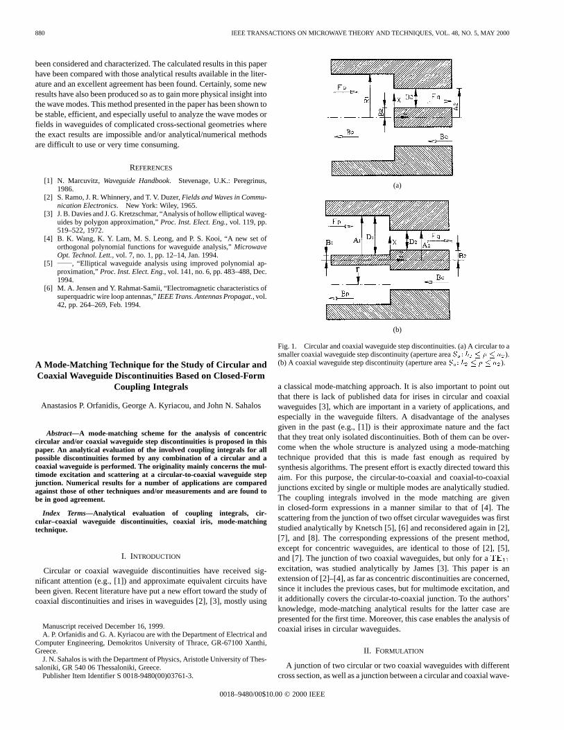
Fig. 1. Circular and coaxial waveguide step discontinuities. (a) A circular to asmaller coaxial waveguide step discontinuity (aperture areaS : b � � � a ).(b) A coaxial waveguide step discontinuity (aperture areaS : b � � � a ).
a classical mode-matching approach. It is also important to point outthat there is lack of published data for irises in circular and coaxialwaveguides [3], which are important in a variety of applications, andespecially in the waveguide filters. A disadvantage of the analysesgiven in the past (e.g., [1]) is their approximate nature and the factthat they treat only isolated discontinuities. Both of them can be over-come when the whole structure is analyzed using a mode-matchingtechnique provided that this is made fast enough as required bysynthesis algorithms. The present effort is exactly directed toward thisaim. For this purpose, the circular-to-coaxial and coaxial-to-coaxialjunctions excited by single or multiple modes are analytically studied.The coupling integrals involved in the mode matching are givenin closed-form expressions in a manner similar to that of [4]. Thescattering from the junction of two offset circular waveguides was firststudied analytically by Knetsch [5], [6] and reconsidered again in [2],[7], and [8]. The corresponding expressions of the present method,except for concentric waveguides, are identical to those of [2], [5],and [7]. The junction of two coaxial waveguides, but only for aTE11
excitation, was studied analytically by James [3]. This paper is anextension of [2]–[4], as far as concentric discontinuities are concerned,since it includes the previous cases, but for multimode excitation, andit additionally covers the circular-to-coaxial junction. To the authors’knowledge, mode-matching analytical results for the latter case arepresented for the first time. Moreover, this case enables the analysis ofcoaxial irises in circular waveguides.
II. FORMULATION
A junction of two circular or two coaxial waveguides with differentcross section, as well as a junction between a circular and coaxial wave-
0018–9480/00$10.00 © 2000 IEEE
IEEE TRANSACTIONS ON MICROWAVE THEORY AND TECHNIQUES, VOL. 48, NO. 5, MAY 2000 881
guide, are considered. For each junction (see Fig. 1), a common axis ofsymmetry (axis-z) for the two waveguides with perfectly conductingwalls is assumed. The electromagnetic field inside each waveguideis expanded into a modal series, e.g., Marcuvitz [1, p. 72]. Modesare numbered in an increasing sequence as they occur. Namelyp =0; 1; 2; 3; � � � denotes TEM,TE11, TM01, TE21, etc. To have thefield expressions independent of the magnitude of the excitation, anormalization of the mode functions to the mode propagating power(Pp) at the junction (z = 0) is made. The normalization coefficientNp is defined asNp = 1= Pp and it can be calculated from [1, pp.67, 73, and 75] for the circular and coaxial waveguides. For the cir-cular and the coaxial waveguides, the mode eigenvalues (�mn, �0
mn)and (kmn; k
0
mn) are correspondingly given in [1, pp. 66–72]. A clas-sical mode-matching technique has been employed, as described in[9], which finally gives the generalized scattering parameters that fullycharacterize the junction. Their expressions are [9, p. 16] as follows:
[SSS11]pq = [QQQ]pq[QQQ]Tpq + [III]
�1
[QQQ]pq[QQQ]Tpq � [I]
and
[SSS12]pq =2 [QQQ]pq[QQQ]Tpq + [III]
�1
[QQQ]pq
[SSS21]pq = [QQQ]Tpq [III]� [SSS11]pq
and
[SSS22]pq = [III]� [QQQ]Tpq[SSS12]pq (1)
The elements of the[QQQ] matrix are known as coupling integrals andresult from the application of the boundary conditions at the junction.These can be alternatively expressed from the electrice(�; ') or themagnetich(�; ') modal functions
[Qpq] = [Qepq] = [Qm
pq]T (2a)
with
QQQeqj =
1
2(YYY p)
1=2(YYY q)�1=2
S
eee IIq � eee Ij ds2: (2b)
YYY p is thepth-mode wave admittance andSSSa is the common area ofthe two waveguides at the junction. Since modes can be either TEM,TE, or TM, the combinations (p; q) in (2) denote coupling betweenthese modes. Integrals of (2) include Bessel functions with different or-ders and arguments and they require an increased computational effort,especially for microwave network synthesis applications. The trans-formation of cylindrical-to-rectangular coordinates (x = � cos � �� sin � and y = � sin � + � cos �) reduces the coupling integralsinto an expression known as the Lommel integral [4]. This integral canbe evaluated analytically, e.g., Abramowitz and Stegun [10, p. 484].For an integrand involving a product of Bessel functionsZm and m
with the same order, we obtain
m(Zm; Bm; a) =a
0
Zm(x1�) m(x2�)� d�
=a
x21 � x22x1Zm+1(x1a) m(x2a)
� x2Zm(x1a) m+1(x2a) (3)
whereZm and m denote any of theJm andYm Bessel functions.For the case of a nonzero lower limit in the integral, e.g., integrating
from b to a, (3) is used twice and another function is introduced as
m(Zm; m) = m(Zm; m; a)� m(Zm; m; b): (4)
The transformation of the modal functions from cylindrical-to-rect-angular coordinates and their substitution in (2) is carried out. Em-ploying the formulas of (3) and (4), we have the following.
• Coupling between two circular waveguides
Qpq = Qmn; il
=
NTEc; pN
TEc; q
p q
�0mn�0
il
R1R2
f�m + 1 + �m�1g;TE - TE
�NTEc; pN
TMc; q
p p q
k0
�0mn�ilR1R2
f�m+1 + �m�1g;TE - TM
0; TM - TM
NTMc; p N
TMc; q
q p
�mn�ilR1R2
f�m+1 + �m�1g;TM - TM
(5)
where
�k =R
0
Jk�mn
R1
� �Jk �ilR2
� � d� = k(Jk; Jk; R2):
• Coupling between a circular and smaller coaxial waveguide [seeFig. 1(a)]
Qpq = Qmn; il
=
NTEc; pN
TEx; q
p q
�0mn�0
il�
4R1
� Y 0
m(�0
ilb)[Xm+1 +Xm�1]
+J 0m(�0
ilb)[m+1 +m�1] ; for TE - TE
�NTEc; pN
TMx; q
p p q
k0
�0mn�il�
4R1
� Ym(�ilb)[Xm�1 �Xm+1]
�Jm(�ilb)[m+1 �m�1] ; for TE - TM
0; for TM - TE
�NTMc; p N
TMx; q
q p
�mn�il�
4R1
� Ym(�ilb)[Xm�1 +Xm+1]
�Jm(�ilb)[m+1 +m�1] ; for TM - TM
�NTMc; p N
TEMx; q
q p
�0n�
R1
J0(�ila)� J0(�ilb) �il;
for TM - TEM(6)
where
Xk =a
b
Jk�mn
R1
� Jk(�il�)� d� = k(Jk; Jk; a; b);
k =a
b
Jk�mn
R1
� Yk(�il�)� d� = k(Jk; Yk; a; b):
• Coupling between a coaxial and a smaller circular waveguide:matricesQpq are the same as for the previous case interchangingp andq as well as�mn and�il.
882 IEEE TRANSACTIONS ON MICROWAVE THEORY AND TECHNIQUES, VOL. 48, NO. 5, MAY 2000
(a)
(b)
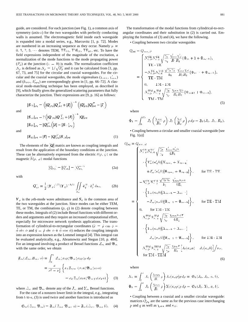
Fig. 2. Small coaxial iris introduced in a circular waveguide. (a) Normalizedshunt inductance for aTE excitation. (b) Normalized shunt susceptance foraTM excitation.
• Coupling between two coaxial waveguides [see Fig. 1(b)]
Qpq =Qmn; il
=
PTEp PTEq p= q �
0
mn�0
il f�+��+g=4;for TE - TE
NTEx; pN
TMx; q
p p q �
0
mn�il �f��+��g=(4k0);for TE - TM
0; for TM - TE
NTMx; pN
TMx; q q= p �mn�il �f�+ ��+g=R1;
for TM - TM
NTMx; pN
TEMx; q p=k0 �0n�Y0(�mnb1)
� J0(�mnb1)�J0(�mnb1) �mn; for TM - TEM
NTEMx; p NTM
x; q k0= q �0l�Y0(�ilb2)
� J0(�ilb2)�J0(�ilb2) �il; for TEM - TM
ln(a=b)= ln(a1=b1) ln(a2=b2); for TEM - TEM(7)
(a)
(b)
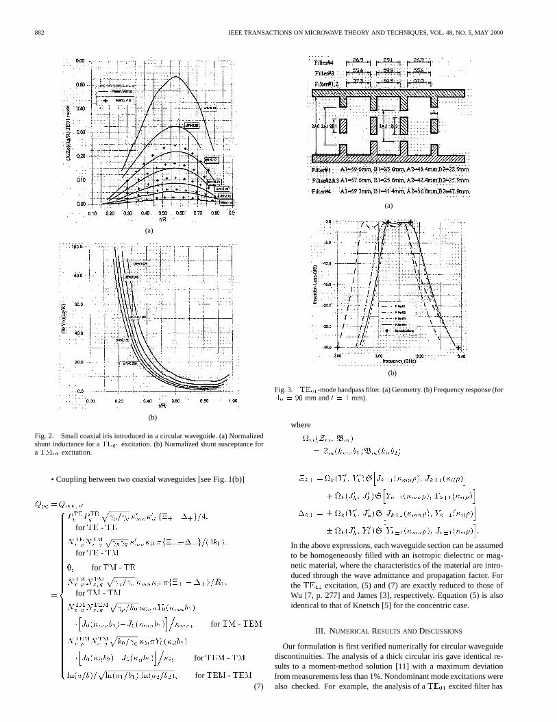
Fig. 3. TE -mode bandpass filter. (a) Geometry. (b) Frequency response (forA = 90 mm andt = 1 mm).
where
m(Zm; m)
= Zm(kmnb1) m(kilb2)
�k� =k(Y0
k; Y0
k) Jk�1(�mn�); Jk�1(�il�)
+ k(J0
k; J0
k) Yk+1(�mn�); Yk+1(�il�)
�k� = � k(Y0
k; J0
k) Jk�1(�mn�); Yk�1(�il�)
� k(J0
k; Y0
k) Yk�1(�mn�); Jk�1(�il�) :
In the above expressions, each waveguide section can be assumedto be homogeneously filled with an isotropic dielectric or mag-netic material, where the characteristics of the material are intro-duced through the wave admittance and propagation factor. FortheTE11 excitation, (5) and (7) are exactly reduced to those ofWu [7, p. 277] and James [3], respectively. Equation (5) is alsoidentical to that of Knetsch [5] for the concentric case.
III. N UMERICAL RESULTS AND DISCUSSIONS
Our formulation is first verified numerically for circular waveguidediscontinuities. The analysis of a thick circular iris gave identical re-sults to a moment-method solution [11] with a maximum deviationfrom measurements less than 1%. Nondominant mode excitations werealso checked. For example, the analysis of aTE01 excited filter has
IEEE TRANSACTIONS ON MICROWAVE THEORY AND TECHNIQUES, VOL. 48, NO. 5, MAY 2000 883
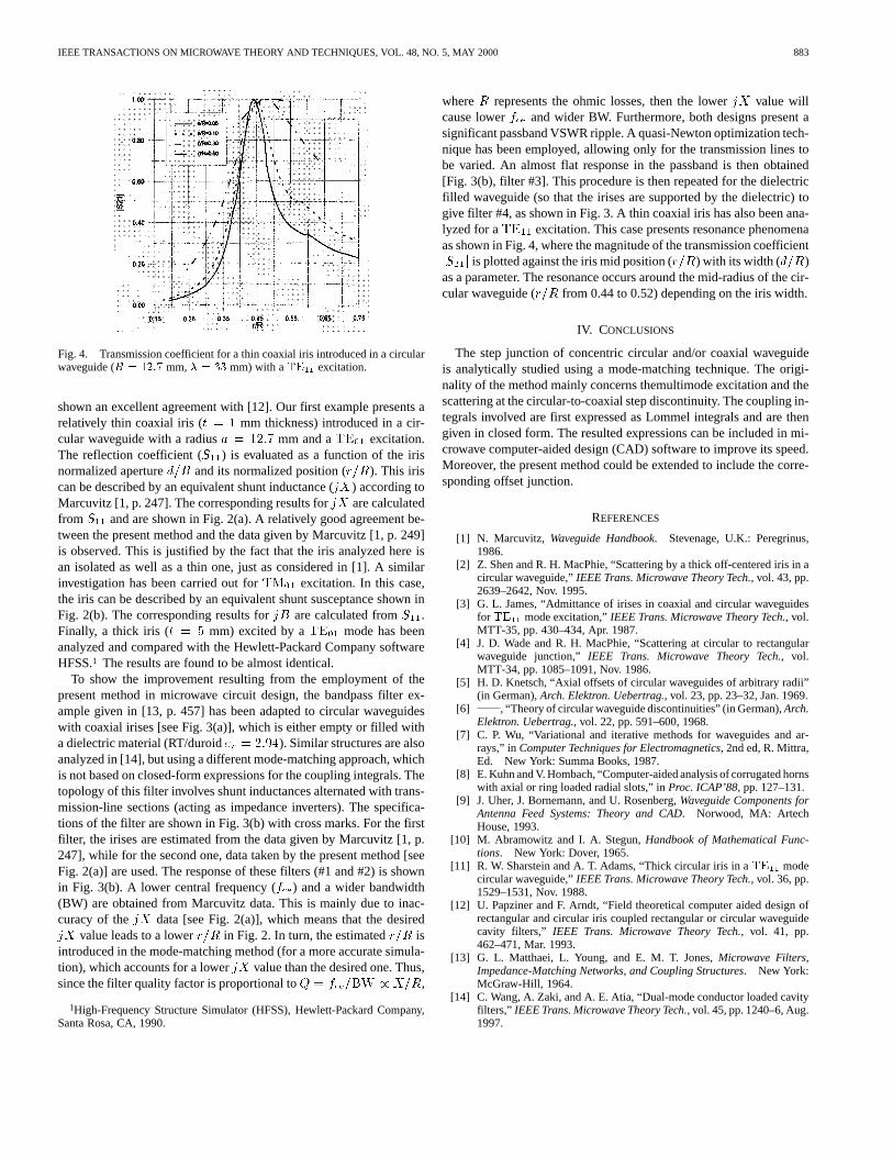
Fig. 4. Transmission coefficient for a thin coaxial iris introduced in a circularwaveguide (R = 12:7 mm,� = 33 mm) with aTE excitation.
shown an excellent agreement with [12]. Our first example presents arelatively thin coaxial iris (t = 1 mm thickness) introduced in a cir-cular waveguide with a radiusa = 12:7 mm and aTE01 excitation.The reflection coefficient (S11) is evaluated as a function of the irisnormalized apertured=R and its normalized position (r=R). This iriscan be described by an equivalent shunt inductance (jX) according toMarcuvitz [1, p. 247]. The corresponding results forjX are calculatedfrom S11 and are shown in Fig. 2(a). A relatively good agreement be-tween the present method and the data given by Marcuvitz [1, p. 249]is observed. This is justified by the fact that the iris analyzed here isan isolated as well as a thin one, just as considered in [1]. A similarinvestigation has been carried out forTM01 excitation. In this case,the iris can be described by an equivalent shunt susceptance shown inFig. 2(b). The corresponding results forjB are calculated fromS11.Finally, a thick iris (t = 5 mm) excited by aTE01 mode has beenanalyzed and compared with the Hewlett-Packard Company softwareHFSS.1 The results are found to be almost identical.
To show the improvement resulting from the employment of thepresent method in microwave circuit design, the bandpass filter ex-ample given in [13, p. 457] has been adapted to circular waveguideswith coaxial irises [see Fig. 3(a)], which is either empty or filled witha dielectric material (RT/duroid"r = 2:94). Similar structures are alsoanalyzed in [14], but using a different mode-matching approach, whichis not based on closed-form expressions for the coupling integrals. Thetopology of this filter involves shunt inductances alternated with trans-mission-line sections (acting as impedance inverters). The specifica-tions of the filter are shown in Fig. 3(b) with cross marks. For the firstfilter, the irises are estimated from the data given by Marcuvitz [1, p.247], while for the second one, data taken by the present method [seeFig. 2(a)] are used. The response of these filters (#1 and #2) is shownin Fig. 3(b). A lower central frequency (fce) and a wider bandwidth(BW) are obtained from Marcuvitz data. This is mainly due to inac-curacy of thejX data [see Fig. 2(a)], which means that the desiredjX value leads to a lowerr=R in Fig. 2. In turn, the estimatedr=R isintroduced in the mode-matching method (for a more accurate simula-tion), which accounts for a lowerjX value than the desired one. Thus,since the filter quality factor is proportional toQ = fce=BW / X=R,
1High-Frequency Structure Simulator (HFSS), Hewlett-Packard Company,Santa Rosa, CA, 1990.
whereR represents the ohmic losses, then the lowerjX value willcause lowerfce and wider BW. Furthermore, both designs present asignificant passband VSWR ripple. A quasi-Newton optimization tech-nique has been employed, allowing only for the transmission lines tobe varied. An almost flat response in the passband is then obtained[Fig. 3(b), filter #3]. This procedure is then repeated for the dielectricfilled waveguide (so that the irises are supported by the dielectric) togive filter #4, as shown in Fig. 3. A thin coaxial iris has also been ana-lyzed for aTE11 excitation. This case presents resonance phenomenaas shown in Fig. 4, where the magnitude of the transmission coefficientjS21j is plotted against the iris mid position (r=R) with its width (d=R)as a parameter. The resonance occurs around the mid-radius of the cir-cular waveguide (r=R from 0.44 to 0.52) depending on the iris width.
IV. CONCLUSIONS
The step junction of concentric circular and/or coaxial waveguideis analytically studied using a mode-matching technique. The origi-nality of the method mainly concerns themultimode excitation and thescattering at the circular-to-coaxial step discontinuity. The coupling in-tegrals involved are first expressed as Lommel integrals and are thengiven in closed form. The resulted expressions can be included in mi-crowave computer-aided design (CAD) software to improve its speed.Moreover, the present method could be extended to include the corre-sponding offset junction.
REFERENCES
[1] N. Marcuvitz, Waveguide Handbook. Stevenage, U.K.: Peregrinus,1986.
[2] Z. Shen and R. H. MacPhie, “Scattering by a thick off-centered iris in acircular waveguide,”IEEE Trans. Microwave Theory Tech., vol. 43, pp.2639–2642, Nov. 1995.
[3] G. L. James, “Admittance of irises in coaxial and circular waveguidesfor TE mode excitation,”IEEE Trans. Microwave Theory Tech., vol.MTT-35, pp. 430–434, Apr. 1987.
[4] J. D. Wade and R. H. MacPhie, “Scattering at circular to rectangularwaveguide junction,” IEEE Trans. Microwave Theory Tech., vol.MTT-34, pp. 1085–1091, Nov. 1986.
[5] H. D. Knetsch, “Axial offsets of circular waveguides of arbitrary radii”(in German),Arch. Elektron. Uebertrag., vol. 23, pp. 23–32, Jan. 1969.
[6] , “Theory of circular waveguide discontinuities” (in German),Arch.Elektron. Uebertrag., vol. 22, pp. 591–600, 1968.
[7] C. P. Wu, “Variational and iterative methods for waveguides and ar-rays,” inComputer Techniques for Electromagnetics, 2nd ed, R. Mittra,Ed. New York: Summa Books, 1987.
[8] E. Kuhn and V. Hombach, “Computer-aided analysis of corrugated hornswith axial or ring loaded radial slots,” inProc. ICAP’88, pp. 127–131.
[9] J. Uher, J. Bornemann, and U. Rosenberg,Waveguide Components forAntenna Feed Systems: Theory and CAD. Norwood, MA: ArtechHouse, 1993.
[10] M. Abramowitz and I. A. Stegun,Handbook of Mathematical Func-tions. New York: Dover, 1965.
[11] R. W. Sharstein and A. T. Adams, “Thick circular iris in aTE modecircular waveguide,”IEEE Trans. Microwave Theory Tech., vol. 36, pp.1529–1531, Nov. 1988.
[12] U. Papziner and F. Arndt, “Field theoretical computer aided design ofrectangular and circular iris coupled rectangular or circular waveguidecavity filters,” IEEE Trans. Microwave Theory Tech., vol. 41, pp.462–471, Mar. 1993.
[13] G. L. Matthaei, L. Young, and E. M. T. Jones,Microwave Filters,Impedance-Matching Networks, and Coupling Structures. New York:McGraw-Hill, 1964.
[14] C. Wang, A. Zaki, and A. E. Atia, “Dual-mode conductor loaded cavityfilters,” IEEE Trans. Microwave Theory Tech., vol. 45, pp. 1240–6, Aug.1997.