Embed Size (px)
Citation preview
A micro membrane vibrator with thermally drivenbimorph cantilever beams
Chun-Chieh Tsao Wensyang Hsu*Graduate Student Assoc. Professor
Institute of Mechanical EngineeringNational Chiao Tung University
Hsin Chu, Taiwan
ABSTRACTA micro membrane vibrator consisting of bimorph cantilever beams and a membrane is designed, fabricated, and tested here.Due to the discrepancy of thermal expansion coefficients between different layers, the membrane moves with temperaturechange. The four-layer structure including Si02-polysilicon-insulated Si02-aluminum is fabricated with four masks. Thenumerical finite element program ANSYS 5 1 is used to investigate the behavior of different designs to have largerdisplacement and force. According to the testing results, we observe that our designs can induce the maximum Z-axisdisplacement up to 1 17 ,um when input power is 6.98 W. The working frequency is about 40 Hz when the amplitude is kept
between 2 and 5 um approximately.
Keywords: bimorph, membrane vibrator, micromachining
1. INTRODUCTIONIn order to allow large volume stroke, two important components of micropumps including membrane vibrators and
chamber structures are developed progressively. In the part of membrane vibrators, choosing the driving types such asmagnetic, electrostatic, piezoelectric and thermal forces is the most important issue to induce a larger volume stroke.
The development of miniaturized fluid pumping systems started in 1980 with the work of Smits and Wallmark usingpiezoelectric bimorphs. In 1988, H. T. G. Van Lintel et a!. presented the micropumps which have a thin glass pumpmembrane actuated by a piezoelectric disc with a diameter of 12.5 mm.[2] In 1989, Masayshi Esashi et al. presented apiezoelectric micropump with the smaller pumping area of 2x2mm2 on a silicon wafer.[31 In 1990, the new actuatingprinciple of an electro-thermopneumatic liquid pump was presented by F. C. M. Van De Dol et al..[4] The pump membraneis driven from gas contained in a cavity controlled by resistive heating. In 1992, a bulk micromachined pump withelectrostatic actuation which can be operated with high frequencies up to 100 Hz was presented by R. Zengerle et al.[l] InI 995, R. Zengerle et a!. presented a bi-directional silicon electrostatic micropump which can be operated with higherfrequencies from 2 kHz to 6 kHz.[5]
According to the correlating research, electrostatic and piezoelectric forces are unstable to deliver the large force.Piezoelectric drives are difficult to manufacture ifthe needed size is below 4mm.[1] Magnetic materials are not compatiblewith the standard IC technology. Therefore, the bimorph effect that is a kind of electro-thermo-mechanical behavior isadopted to be the primary driving principle for its large force and high compatibility with IC fabrication. Here, a micromembrane vibrator with four layers including SlO, -polysilicon-SiO, - aluminum will be designed and fabricated to act as
the driving component of micropumps.
2. DESIGN PRINCIPLE OF MICRO MEMBRANE VIBRATORSAs shown in Figure 2. 1 , two designed bimorph beams consist of aluminum film on top and two layers below : Si02 and
polysilicon in sequence. Aluminum and Si02 are chosen because of the large discrepancy of their thermal expansioncoefficients. Polysilicon layer provides the source of heaters. After applying electric current to the polysilicon layer, the
*W H. (correspondence): E-mail: [email protected]; Telephone: 88635712121-55111; FAX: 88635720634
195SPIE Vol. 3241 . 0277-786X/971$lO.OO
Downloaded From: http://proceedings.spiedigitallibrary.org/ on 04/28/2014 Terms of Use: http://spiedl.org/terms

temperature rises and the himorph beam bends downward along negative Z-axis. The curvature, k=1/r, is expressed forrectangular cross sections as following.
k =
- 6blb2E1E2t112(t1+12)(a2-a1)AT ' (1)-(ME1112)2 +(b2E2•t22)2 +2blb2E1E2tlt2(2t12 +3t1t2+2t22)
r : the radius of curvature of the beamA T : the change in temperature
E1,E2 : Young's modulusI 2 : the thermal expansion coefficients
ti, t2 : the thickness ofdifferent layersbi, b2 : the width ofdifferent layers
The deflection d at the free end ofthe bimorph beam from the constant curvature k introduced by thermal strain is
d=— for L<<r , (2)2
Figure 2.2 shows the simulation ofthe tip displacement along Z-axis for the rectangular and trapezoidal bimorph beamsfrom top view heated at 200 ° Cuniformly by Ansys 5 . 1 . The thicknesses of aluminum, Si02 and polysilicon films are 1.0,0.5 and 0.3 urn respectively. Figure 2.3 shows the finite element analysis results and the tip deflection calculated by usinganalytical model. The maximum difference between the analytic model and Ansys 5. 1 is 1 .409 %. Furthermore, changing theshapes of polysilicon layers is also simulated that the design (b) enables to have larger displacement along Z axis than design(a) in Figure 2.4.
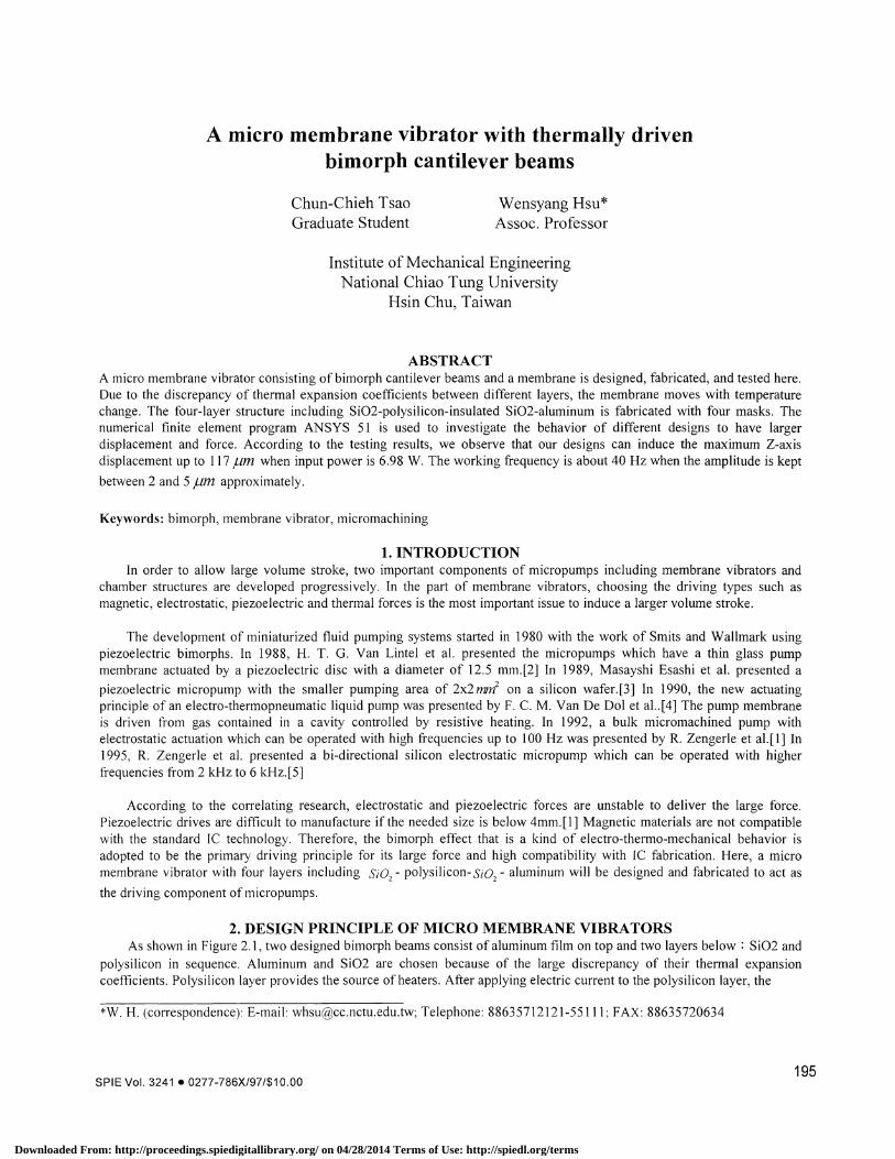
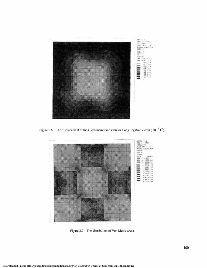
By means of attaching four bimorph beams to the membrane, a micro membrane vibrator is shown in Figure 2.5. Asheating four bimorph beams, the bottom membrane deflects due to the bending of the beams. Figure 2.3-3 shows thedisplacement of the micro membrane vibrator along Z-axis in simulation as four beams are heated to 200 °cuniformly. Themaximum displacement along negative Z-axis is 93.753 jtm and the net volume stroke is 23.95x 10⁶ 1um3. Figure 2.7 showsthe distribution of Von Mesis stress. The maximum Von Mesis stress is 0.56 GPa in the base of four bimorph beams. Thestress also concentrates in the membrane obviously. The factor of safety is about 12.5. The maximum deflection is generallyproportional to temperature as shown in Figure 2.8.
heating resistor
360
-:a
Aluminum
flllPoly-Si
196
unit:
Figure 2.1 Materials of two bimorph beam structures
Downloaded From: http://proceedings.spiedigitallibrary.org/ on 04/28/2014 Terms of Use: http://spiedl.org/terms

(ID
Nt(O
C
E0
(ID
H
(b) Trapezoidal type ( maximum deflection : 263.82 ,um)
Figure 2.2 Simulations ofthe tip displacement along Z-axis from top view
—4— Analysis (rect.) —— FEM (rect.) —&--- FEM (trap.)
300
250
200
150
100
50
040 60 80 100 120 140 160 180 200
Temperature (degree)
Figure 2.3 The results offinite element analysis and analytical model
I 97
Downloaded From: http://proceedings.spiedigitallibrary.org/ on 04/28/2014 Terms of Use: http://spiedl.org/terms

198
Design (b) Maximum deflection (199.425 /1)Figure 2.4 Two designs and the finite element results in polysilicon layer
1.0
0.5
0.3
1.0
Design (a) Maximum deflection (145.163 pm)
Figure 2.5 The dimensions of the micro membrane vibrator
Downloaded From: http://proceedings.spiedigitallibrary.org/ on 04/28/2014 Terms of Use: http://spiedl.org/terms
aSSS
Figure 2.6 The displacement of the micro membrane vibrator along negative Z-axis (200 °C)
iaSa':S
199
Figure 2.7 The distribution of Von Mesis stress
Downloaded From: http://proceedings.spiedigitallibrary.org/ on 04/28/2014 Terms of Use: http://spiedl.org/terms

160
140
120
!800I)6040
20
0
50 100 150 200 250 300
Figure 2.8 The maximum Z-axis deflection vs. Temperature
3. FABRICATIONA Si02 film of 1 .0 urn is oxidized firstly in a double-polished wafer that is regarded as the membrane of the
microvibrator. By means of KOH etching selectivity between Si02 and Si, this film can also defend against KOH etching inthe front side of wafers during KOH backside etching. In order to heat the bimorph beam, a layer of polysilicon with POC13driven-in under the bimorph beam is deposited about 3000 A to be the heating resistor. The temperature rises as electriccurrent passes through polysilicon film. After patterning the polysilicon layers, heating resistors and electric contact pads aredefined respectively. These steps are shown in Figure 3.1 (a)-(d).
Because of large discrepancy of thermal expansion coefficients and small Young's modulus, 5i02 and Aluminum arechosen to be the bimorph materials. The second 5i02 film is oxidized thermally about 5000 A between polysilicon andaluminum layers, which not only constructs the bimorph beam but isolates polysilicon and aluminum films. After patterningthe second 5i02 film, aluminum is evaporated upon the second 5i02 layer and patterned. The steps are illustrated in Figure3 . 1 (e)-(h). Before patterning 5i02 films in the back side of the wafer, photoresist are coated and baked in the front side toprotect from etching 5i02 films. The IR aligner is helpful to align the patterns in opposite side. The steps are shown inFigure 3.1 (i)-(k).
During the process of KOH backside etching , the devices in the front side are protected by the acrylic chuck as Figure3.1 (1) shows. Until the silicon is etched appropriately, the membrane vibrators with four bimorph beams and a membraneare completed after removing the acrylic chuck as shown in Figure 3.1 (m).
200
(a) Initial RCA clean
double-polished water
(c) LPCVD polysilicon
double-polished wafer
(b) Wet oxidation Si02-(1)
double-polished wafer
(d) Mask #1 etching polysilicon
double-polished wafer
Temp. °C
Downloaded From: http://proceedings.spiedigitallibrary.org/ on 04/28/2014 Terms of Use: http://spiedl.org/terms

(e) Wet oxidation Si02-(2)
Zt277&OZ#V///7///Y//('/ _______ (V( ½'''
double-polished water
(I) Mask #2 etching Si02-(2)
V///ØY/({//(//(//(///V/((áfr'7{/
double-polished water
(g) Aluminum evaporation
double-polished water
(i) Coating photoresist
.: ///// / ;/(I !I !i !i! i!i ! I 1 !j 1 !j ! i!iJ Ii!i 1 !f!i!i!I 1 1
Ldouble-polished water
(h) Same mask #2 etching aluminum
C) IR Aligner mask #3 in the back side
(m) Remove acrylic and strong adhesive
Si02-<1>
mnic Polysilicon & P drive-in
Si02-<2>
Aluminum
Strong adhesive
Figure 3.2-1 Fabrication process
201
(k) Etching Si02-(l) in the back side (1) KOH etch silicon in the back side
himorph beam
heating resistormicro membrane
contact pad
Downloaded From: http://proceedings.spiedigitallibrary.org/ on 04/28/2014 Terms of Use: http://spiedl.org/terms
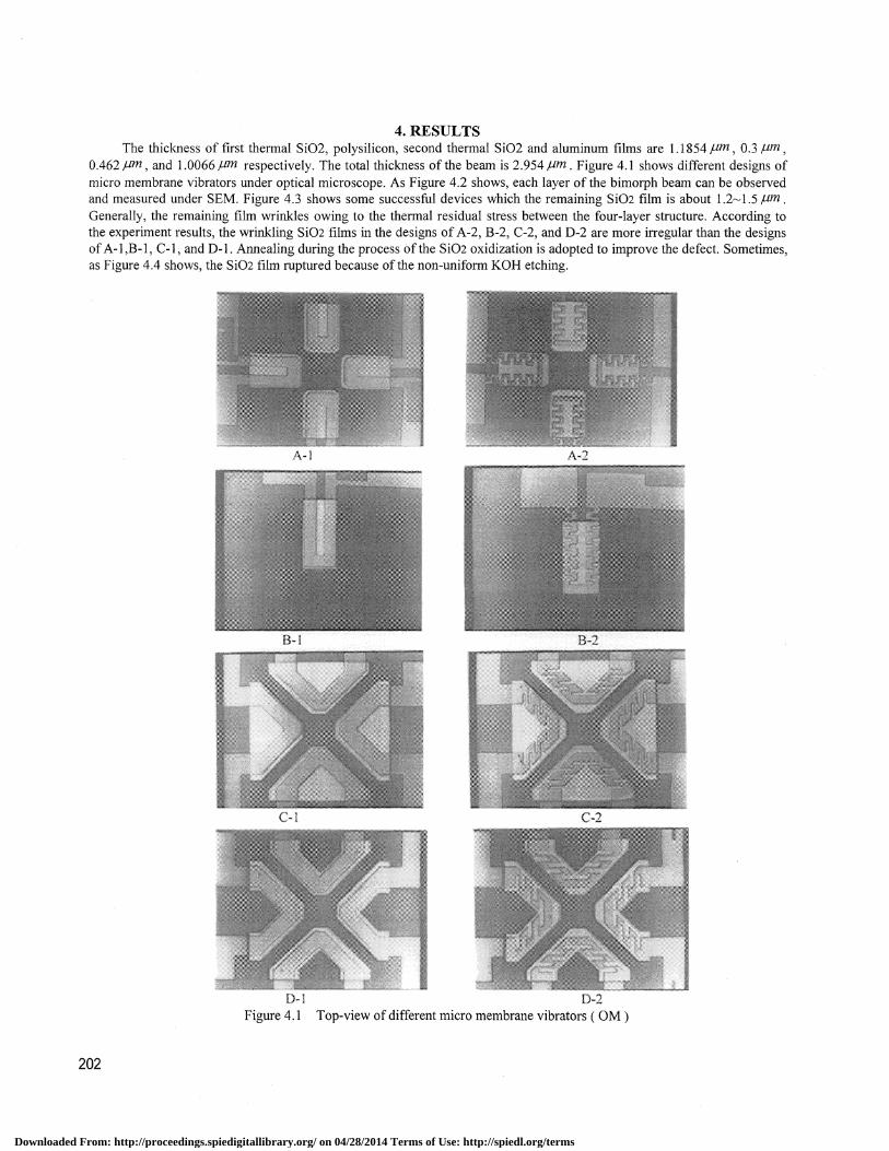
4. RESULTSThe thickness of first thermal Si02, polysilicon, second thermal Si02 and aluminum films are 1 .1854 /tm ,0.3 tim,
0.462 tim , and 1 .0066 pm respectively. The total thickness of the beam is 2.954im . Figure 4. 1 shows different designs ofmicro membrane vibrators under optical microscope. As Figure 4.2 shows, each layer of the bimorph beam can be observedand measured under SEM. Figure 4.3 shows some successful devices which the remaining Si02 film is about 1 .21 .5tim.Generally, the remaining film wrinkles owing to the thermal residual stress between the four-layer structure. According tothe experiment results, the wrinkling Si02 films in the designs of A-2, B-2, C-2, and D-2 are more irregular than the designsof A-l,B-1, C-i, and D-l. Annealing during the process of the Si02 oxidization is adopted to improve the defect. Sometimes,as Figure 4.4 shows, the Si02 film ruptured because of the non-uniform KOH etching.
202
Figure 4.1 Top-view of different micro membrane vibrators ( OM)
Downloaded From: http://proceedings.spiedigitallibrary.org/ on 04/28/2014 Terms of Use: http://spiedl.org/terms

Figure 4.3 Top view ofsuccessful devices from the backside (C-i, C-2)
Figure 4.4 The remaining ruptured films owing to non-uniform KOH etching
203
i .k t : w
Figure 4.2 SEM shows the bimorph beam structures
Downloaded From: http://proceedings.spiedigitallibrary.org/ on 04/28/2014 Terms of Use: http://spiedl.org/terms
204
U(ci
I he broken part
The melted partI:
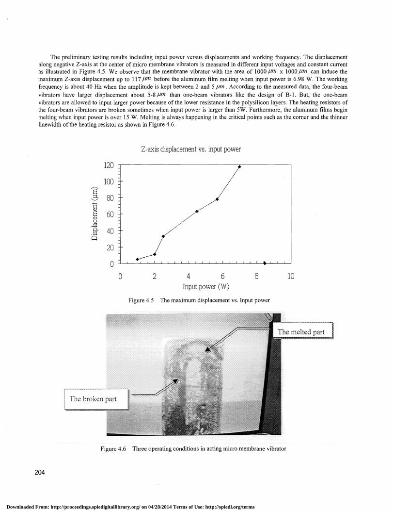
The preliminary testing results including input power versus displacements and working frequency. The displacementalong negative Z-axis at the center of micro membrane vibrators is measured in different input voltages and constant currentas illustrated in Figure 4.5 . We observe that the membrane vibrator with the area of 1000 tm x 1000 /m can induce themaximum Z-axis displacement up to 1 17 pm before the aluminum film melting when input power is 6.98 W. The workingfrequency is about 40 Hz when the amplitude is kept between 2 and 5 ,um .According to the measured data, the four-beamvibrators have larger displacement about 5-8 /Lm than one-beam vibrators like the design of B- 1 . But, the one-beamvibrators are allowed to input larger power because of the lower resistance in the polysilicon layers. The heating resistors ofthe four-beam vibrators are broken sometimes when input power is larger than SW. Furthermore, the aluminum films beginmelting when input power is over 15 W. Melting is always happening in the critical points such as the corner and the thinnerlinewidth of the heating resistor as shown in Figure 4.6.
Z-axis displacement vs. input power
120
100
80
60
40
20
0
0 2 4 6 8 10
Input power (W)
Figure 4.5 The maximum displacement vs. Input power
Figure 4.6 Three operating conditions in acting micro membrane vibrator
Downloaded From: http://proceedings.spiedigitallibrary.org/ on 04/28/2014 Terms of Use: http://spiedl.org/terms

5. CONCLUSIONSThe preliminary micro membrane vibrator has been designed, fabricated and tested. Our designs can induce the large
deflection up to 1 1 7 jim . Although the driving frequency of the thermally driven membrane has to be low, the devices canwork properly at 40 Hz when the amplitude is kept between 2 and 5,um . The improved and simplified fabrication process isunder way.
6. ACKNOWLEDGMENTSThe Semiconductor Research Center in National Chiao Tung University provides facilitation experiment. The associate
Researcher, Yuh-Sheng Lin, and Micro-Electro-Mechanical Systems of Mechanical Industry Research Laboratories inIndustrial Technology Research Institute are acknowledged for providing fabrication in measuriement. The project issupported by National Science Council under grant N5C86-2221-E009-042.
7. REFERENCE1 . R. Zengerle, A. Richter, H. Sandmaier, "A MICRO MEMBRANE PUMP WITH ELECTROSTATIC ACTUATION",
Sensors and Actuators, 20(1989) 163-169.2. H. T. G. Van Lintel, "A PIEZOELECTRIC MICROPUMP BASED ON MIRO-MACHINING OF SILICON", Sensors
and actuators, 15(1988) 153-167.3. Massayoshi Esashi, Shuichi Shoji and Akira Nakano, "Normally Closed Microvalve and Micropump Fabricated on a
Silicon Wafer', Sensors and Actuators, 20(1989) 163-169.4. F. C. M. Van De Pol, H. T. G. Van Lintel, M. Elwenspoek and J. H. J. Fluitman, "A Thermopneumatic Micropump Based
on Micro-engineering Techniques", Sensors and Actuators, A21-A23 (1990) 198-202.5. R. Zengerle, S. Kiuge, M. Richter, A. Richter, "A Bidirectional Silicon Micro-pump", 1995 IEEE.
205
Downloaded From: http://proceedings.spiedigitallibrary.org/ on 04/28/2014 Terms of Use: http://spiedl.org/terms