Embed Size (px)
Citation preview
A METHODOLOGY TO DEVELOP ONTOLOGY OF
ADDITIVE MANUFACTURING USING FORMAL
ATTRIBUTES SPECIFICATION TEMPLATE (FAST)
SYAZWANI BT MOHD HASHIM
B051110040
UNIVERSITI TEKNIKAL MALAYSIA MELAKA
2015

B051110040 B
AC
HE
LOR
OF
MA
NU
FA
CT
UR
ING
EN
GIN
EE
RIN
G (M
AN
UF
AC
TU
RIN
G D
ES
IGN
) (HO
NS
.) 2015 UT
eM
UNIVERSITI TEKNIKAL MALAYSIA MELAKA
BORANG PENGESAHAN STATUS LAPORAN PROJEK SARJANA MUDA
TAJUK: A Methodology to Develop Ontology of AM Using Formal Attributes
SESI PENGAJIAN: 2014/15 Semester 2 Saya : SYAZWANI BT MOHD HASHIM mengaku membenarkan Laporan PSM ini disimpan di Perpustakaan Universiti Teknikal Malaysia Melaka (UTeM) dengan syarat-syarat kegunaan seperti berikut:
1. Laporan PSM adalah hak milik Universiti Teknikal Malaysia Melaka dan penulis. 2. Perpustakaan Universiti Teknikal Malaysia Melaka dibenarkan membuat salinan
untuk tujuan pengajian sahaja dengan izin penulis. 3. Perpustakaan dibenarkan membuat salinan laporan PSM ini sebagai bahan
pertukaran antara institusi pengajian tinggi.
4. **Sila tandakan ( )
SULIT
TERHAD
TIDAK TERHAD
(Mengandungi maklumat yang berdarjah keselamatan atau kepentingan Malaysia sebagaimana yang termaktub dalam AKTA RAHSIA RASMI 1972)
(Mengandungi maklumat TERHAD yang telah ditentukan oleh organisasi/badan di mana penyelidikan dijalankan)
(TANDATANGAN PENULIS)
Alamat Tetap: NO. 21 B Kampung Batang Kulim
Kota Lama Kanan,33040
Kuala Kangsar , Perak Darul Ridzuan
Tarikh: 24JUNE 2015
Disahkan oleh:
(TANDATANGAN PENYELIA)
Cop Rasmi:
Tarikh:
** Jika Laporan PSM ini SULIT atau TERHAD, sila lampirkan surat daripada pihak berkuasa/organisasi berkenaan dengan menyatakan sekali sebab dan tempoh laporan PSM ini perlu dikelaskan sebagai SULIT atau TERHAD.
DECLARATION
I hereby, declared this report entitled “A Methodology to Develop Ontology of Additive
Manufacturing Using Formal Attributes Specification Template (FAST)” is the result of
my own research except as cited in references.
Signature : ……………………………………………….
Author’s Name : ……………………………………………….
Date : ………………………………………………..
APPROVAL
This report is submitted to the Faculty of Manufacturing Engineering of UTeM as a partial
fulfillment of the requirements for the degree of Bachelor of Manufacturing Engineering
(Manufacturing Design) with Honours. The member of the supervisory committee is as
follow
………………………………….
(Supervisor)
UNIVERSITI TEKNIKAL MALAYSIA MELAKA
A METHODOLOGY TO DEVELOP ONTOLOGY OF ADDITIVE
MANUFACTURING USING FORMAL ATTRIBUTES
SPECIFICATION TEMPLATE (FAST)
This report is submitted in accordance with requirement of the Universiti Teknikal
Malaysia Melaka (UTeM) for Bachelor Degree of Manufacturing Engineering (Design)
with Honours
By
SYAZWANI BT MOHD HASHIM
B05111040
921103085294
FACULTY OF MANUFACTURING ENGINEERING
2015
i
ABSTRACT
Additive Manufacturing offers design creativity and freedom in product developing
process. As a result, large number of design information is generated and accumulated.
This resulting a time consuming for designer in searching the right information. In this
project the additive manufacturing processes have been classified according to their
attributes and an ontology of additive manufacturing is developed. Ontology allows the
designers to obtain knowledge from previous method to be shared and reused for future
references. The key point in developing the AM ontology is the combination of Formal
Concept Analysis (FCA) and attribute that is obtained using a systematic guidelines called
Formal Attributes and Specification Template (FAST). The attributes are characterized in
terms of its mereological and topological structure and its involvement with one or more
processes. FAST express the formal attributes in terms of: (1) inputs (a.k.a objects that are
always changed by the process); (2) outputs (a.k.a objects that are always produced by the
process); (3) participating physical objects (including locations, agents, and performer)
other than inputs and outputs; (4) sub-activities (a.k.a sub-activities that compose the
process). FCA is a method based on applied lattice and order theory, is selected as the
taxonomy generator (class hierarchy).The developed class hierarchy was evaluated by
homogeneous cluster analysis. The results of evaluation show that FAST method allow the
finding of similarities between classes.
ii
ABSTRAK
Additive Manufacturing adalah teknologi yang memberi peluang kreativiti dan kebebasan
dalam proses menghasilkan produk. Ini telah menyebabkan pengumpulan data yang terlalu
banyak. Berikutan itu, mencari informasi yang mengambil masa yang lama. Dalam projek
ini proses additive manufacturing telah di kelaskan mengikut ciri setiap proses dan
ontology telah dibina. Ontology dibina adalah untuk membolehkan ilmu atau pengetahuan
daripada kaedah yang telah digunapakai terhadap proses-proses terdahulu dapat
dikongsikan dan diguna semula untuk rujukan di masa hadapan. Kunci kepada penghasilan
AM ontology adalah dengan kombinasi kaedah Formal Concept Attributes (FCA) dan
Formal Attributes Specification Template (FAST). Ciri-ciri proses telah dikelaskan
mengikut merelogi dan struktur topologi dan kaitan antara suatu proses dengan proses
yang lain. FAST mencirikan kelas mengikut kriteria (1) input (objek yang sentiasa berubah
megikut proses); (2) outputs (objek yang sentiasa dihasilkan oleh proses); (3) fizikal objek
yang terlibat ( termasuk lokasi, agen dan pelaku) selain daripada input dan output, (4) sub-
aktiviti ( sub-aktiviti yang membantu proses utama). Kaedah FCA yang menghasilkan
lattice dan teori susunan telah digunakan sebagai taxonomy generato untuk pembinaan
kelas hierarki. Pembinaa kelas hierarki kemudiannya di nilai melalui homogeneous cluster
analysis. Keputusan penilaian telah menunjukkan FAST dapat membantu dalam mencari
ciri yang sama antara kelas.

iii
DEDICATION
Dedicated to my father, Mohd Hashim b. Ayob and my mother Shandi bt Ngah Ahmad,
beloved brother and sister, friends and most of all to my supervisor without whom this
project would have been completed within a year.
iv
ACKNOWLEDGEMENT
Alhamdullilah, I praised and thank to Allah S.W.T for his greatness of giving me
strength and courage to complete this project. My appreciation goes to many people who
has assisted me throughout the completion of this project. I am indebted to my family
especially my parents for their encouragement and support. My deepest appreciation and
gratitude goes to my supervisor, Dr. Suriati bt Akmal , for her valuable time, guidance,
insights, unconditional support, and patience that made this project attainable. My special
thanks go to my panels for their valuable advices and last but not least, I would like to
thank to my friends for all their contribution directly or indirectly in giving opinion,
sharing, motivate and inspired me to to complete this work.
v
TABLE OF CONTENTS
Abstract .................................................................................................................................. i
Abstrak .................................................................................................................................. ii
Dedication ............................................................................................................................ iii
Acknowledgement ............................................................................................................... iv
Table of Content ................................................................................................................... v
List of Tables ..................................................................................................................... viii
List of Figures ...................................................................................................................... ix
List of Abbreviation ............................................................................................................. xi
1. INTRODUCTION........................................................................................................... 1
1.1 Background.............................................................................................................. 1
1.2 Problem Statement................................................................................................... 3
1.3 Objective .................................................................................................................. 4
1.4 Scope ....................................................................................................................... 4
2. LITERATURE REVIEW .............................................................................................. 5
2.1 Additive Manufacturing .......................................................................................... 5
2.1.1 What is Additive Manufacturing ..................................................................... 5
2.1.2 Additive Manufacturing Processes .................................................................. 7
2.2 Ontology ................................................................................................................ 16
2.2.1 What is Ontology ........................................................................................... 16
2.2.2 Methodology of Ontology.............................................................................. 18
vi
2.2.3 Ontology Engineering .................................................................................... 19
2.2.4 Ontology for a Process ................................................................................... 21
2.2.5 Formal Concept Analysis ............................................................................... 22
3. METHODOLOGY ....................................................................................................... 24
3.1 Introduction ........................................................................................................... 24
3.2 Development of Ontology ..................................................................................... 24
3.2.1 Step 1 : Identification of the purpose and scope of the project ...................... 25
3.2.2 Step 2 : Identification of the potential classes to be defined under the scope of
the project................................................................................................................ 25
3.2.3 Step 3 : Identification of the formal attributes ............................................... 25
3.2.4 Step 4 : Identification of the formal attributes ............................................... 28
3.2.5 Step 5 : Use the FCA to generate concept lattice........................................... 29
3.2.6 Step 6 : Analyze the lattice and resolve inconsistencies ................................ 30
3.2.7 Step 7 : Create a class hierarchy with an upper ontology .............................. 31
3.2.8 Step 8 : Integrate the class hierarchy with an upper ontology ....................... 31
3.2.9 Step 9 : Formally define each class by adding axioms, additional classes and
relationship .............................................................................................................. 31
4. RESULT AND DISCUSSION ..................................................................................... 32
4.1 Ontology for Additive Manufacturing Process .................................................... 32
4.2 FAST .................................................................................................................... 33
4.3 Ontology Construction .......................................................................................... 34
4.4 Evaluation of Ontology .... 49
vii
5. CONCLUSION AND RECOMMENDATION .......................................................... 52
5.1 Conclusion ............................................................................................................ 52
5.2 Recommendation .................................................................................................. 53
REFERENCES .................................................................................................................. 54
viii
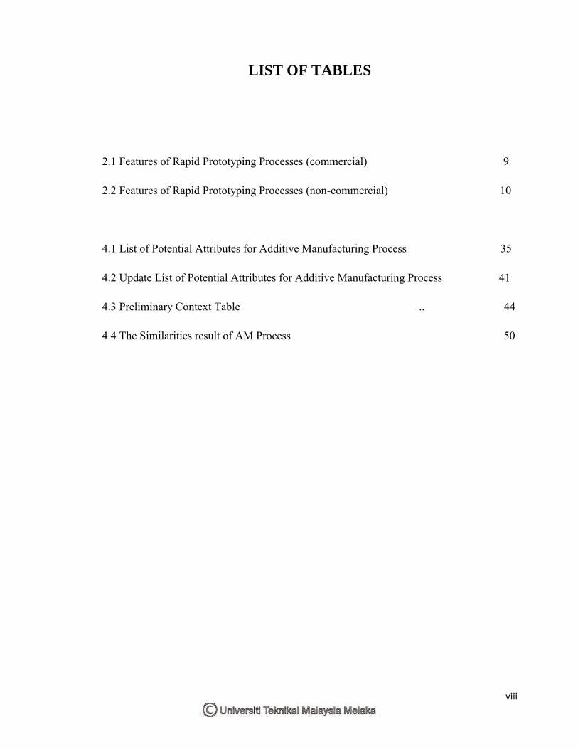
LIST OF TABLES
2.1 Features of Rapid Prototyping Processes (commercial) 9
2.2 Features of Rapid Prototyping Processes (non-commercial) 10
4.1 List of Potential Attributes for Additive Manufacturing Process 35
4.2 Update List of Potential Attributes for Additive Manufacturing Process 41
4.3 Preliminary Context Table .. 44
4.4 The Similarities result of AM Process 50
ix
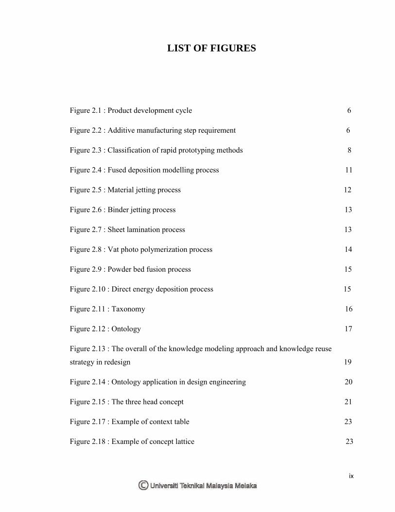
LIST OF FIGURES
Figure 2.1 : Product development cycle 6
Figure 2.2 : Additive manufacturing step requirement 6
Figure 2.3 : Classification of rapid prototyping methods 8
Figure 2.4 : Fused deposition modelling process 11
Figure 2.5 : Material jetting process 12
Figure 2.6 : Binder jetting process 13
Figure 2.7 : Sheet lamination process 13
Figure 2.8 : Vat photo polymerization process 14
Figure 2.9 : Powder bed fusion process 15
Figure 2.10 : Direct energy deposition process 15
Figure 2.11 : Taxonomy 16
Figure 2.12 : Ontology 17
Figure 2.13 : The overall of the knowledge modeling approach and knowledge reuse
strategy in redesign 19
Figure 2.14 : Ontology application in design engineering 20
Figure 2.15 : The three head concept 21
Figure 2.17 : Example of context table 23
Figure 2.18 : Example of concept lattice 23
x
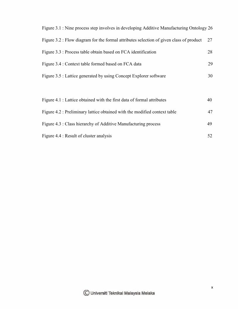
Figure 3.1 : Nine process step involves in developing Additive Manufacturing Ontology 26
Figure 3.2 : Flow diagram for the formal attributes selection of given class of product 27
Figure 3.3 : Process table obtain based on FCA identification 28
Figure 3.4 : Context table formed based on FCA data 29
Figure 3.5 : Lattice generated by using Concept Explorer software 30
Figure 4.1 : Lattice obtained with the first data of formal attributes 40
Figure 4.2 : Preliminary lattice obtained with the modified context table 47
Figure 4.3 : Class hierarchy of Additive Manufacturing process 49
Figure 4.4 : Result of cluster analysis 52
xi
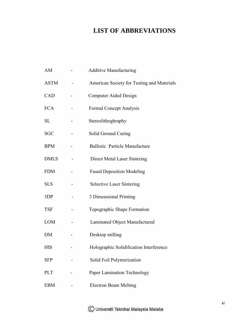
LIST OF ABBREVIATIONS
AM - Additive Manufacturing
ASTM - American Society for Testing and Materials
CAD - Computer Aided Design
FCA - Formal Concept Analysis
SL - Stereolithoghraphy
SGC - Solid Ground Curing
BPM - Ballistic Particle Manufacture
DMLS - Direct Metal Laser Sintering
FDM - Fused Deposition Modeling
SLS - Selective Laser Sintering
3DP - 3 Dimensional Printing
TSF - Topographic Shape Formation
LOM - Laminated Object Manufactured
DM - Desktop milling
HIS - Holographic Solidification Interference
SFP - Solid Foil Polymerization
PLT - Paper Lamination Technology
EBM - Electron Beam Melting

xii
DED - Direct Energy Deposition
MASON - Manufacturing Semantic Ontology
FAST - Formal Attributes Specification Template
1
CHAPTER 1
INTRODUCTION
1.1 Background
There are two ways of manufacturing methods for creating a physical object, subtractive
and additive manufacturing process. The subtractive manufacturing process is the
traditional process which involves a removal of material. An example of the process are
milling, drilling, and boring. While additive manufacturing (AM) is another method of
manufacturing process that involves the latest technologies in which part are produced by
adding layer-by-[layer deposition of material. AM offers a geometrical freedom, such as
design complexity, part consolidation, parts customization and material combination for
each part production. The additive manufacturing cycle consists of geometric creation
using modeling modeler, determination of suitable deposition orientation, slicing,
generation of material deposition paths, part deposition and post processing operations
(Thrimurthulu et al., 2003).
In order to develop the Ontology of Additive Manufacturing the classification of each
process is necessary and important to obtain the information and characterize the potential
process classes. AM consist of four categories; (1) powder bed process, (2) material
deposition process, (3) 3D printing and (4) liquid. Each category is only suitable for certain
AM methods. As an example, powder bed processes category is for the laser sintering (LS)
, laser melting (LM) and electron beam melting (EBM) methods which do not involve the
blown powder or extrusion process. Gibson et al. (2010) found that Pham (1998) made a
2
comprehensive two dimensional classification method based on earlier documented
process classification made by Kruth (1991). The first dimension refers to the method by
which the layers are constructed. The earlier development of AM technology is a single
point source which is implemented to draw across the surface of base material. Then the
system has developed a new method by adding the sources in order to increase the
throughput example are 1D, 2x1D, array of 1D channel and 2D channel. However, this
classifications results in numerous dissimilar processes that are grouped together. Also,
this work added material as a new factor for further classification and improvement. The
method proposed by Pham (1998) is lacking of the deposition of composite material using
and extrusion based system as the material is excluded in their data. As with many
classification there can be sometimes processes or system that lie outside them. (Gibson et
al., 2010)
The classification of these processes were keep changing from time to time parallel with
the evolution of CAD technology. Therefore, the proper classification data of AM process
is required in order to enable the designer have the advantage of design creativity and
freedom of AM in which it faster the product development time.
Recently, the use of ontologies for managing the information and knowledge of AM has
been reported in literature. Ontology is one approach to the computer representation of
processes, it captured the semantics of things represented in specific domain which
compose of classes represent a set of things that share the same attributes (Akmal &
Batres, 2013). It is popular in engineering knowledge modeling and retrieval for its
overwhelming searching ability than exact-match searching method (Liu et al., 2010). It
has been used for the last decades for a set of tasks such as improving communication
between agents (human/software) or reusing data model or knowledge schema. All these
tasks deal with the capability of being used or operated reciprocally and can be applied in
different domains. Consequently, ontologies have evolved and several kinds of ontologies
have been proposed in different field (Roussey, 2011). Several ontologies have been
developed for generic knowledge representation for example PRONTO, MASON and
ADACOR.
3
In developing and ontology-based for redesigning process plans in AM, Liu and
Rosen(2010) suggest that the knowledge modeling techniques support the application from
three aspects ; (1) design feature ontology , (2) representation of manufacturing rules and
(3) redesign flow of process planning. The key idea is that a new process plan under new
manufacturing requirement could be obtained by modification of certain variables of the
current process. Therefore, in this project, a methodology to develop AM ontology using a
systematic guideline of formal attributes characterization and formal concept analysis is
proposed.
1.2 Problem statement
There are numerous ways to classify AM technologies. A popular approach is to classify
according to baseline technology, like whether the process uses lasers, printer technology,
extrusion technology, etc. Another approach is to collect processes together according to
the type of raw material input (Gibson et al., 2010). The problem with these classification
methods is that some processes get lumped together in what seems to be an odd
combination and there is no clear representation of data that can be understand and access
by the user easily. Example like Selective Laser Sintering being grouped together with 3D
printing or that some processes that may appear to produce similar result end up being
separated (Gibson et al., 2010). Therefore, in order to have a better data classification for
additive manufacturing, a formal concept analysis (FCA) is used. Formal concept analysis
is a technique for knowledge processing that is based on applied lattice and order theory.
4
1.3 Objective
1. To classify the additive manufacturing processes according to their processes
attributes
2. To develop an ontology of additive manufacturing using the combination of formal
concept analysis and a set of process characterization.
1.4 Scope
In developing this ontology for additive manufacturing a formal concept analysis (FCA)
will be used in order to obtain the functional system required. The FCA concepts can be
partially ordered into a lattice, which a main concepts subsumes another concept. Lattice
concept will be generated by using a proper algorithm. From that a context table can be
generated which allow to determine the subclass and attribute of a system. The attributes
stated in this research according to the relationship between additive manufacturing
process, material and the channel use to distribute the layer. Resulted from the data, a class
hierarchy will be develop and convert it into a computer-processable form by using
Protégé ontology editor. Protégé will facilitates the specification of classes, relation and
axioms. Then, OWL language is used to save the ontologies which will be useful for
automatic reasoning and integration.
5
CHAPTER 2
LITERATURE REVIEW
2.1 Additive Manufacturing
2.1.1 What is additive Manufacturing
Additive layer manufacturing, or rapid prototyping, rapid manufacturing, layered
manufacturing, direct digital manufacturing, solid free form fabrication, digital
manufacturing and freeform fabrication are the other names that can be used to represent
the additive manufacturing. AM is a process of producing a product by receiving a 3D
CAD data from any design software which then will be converted into an STL file before
sending it to the machine for fabrication. This usually involves an addition of material
layer by layer. Gradually AM technology has simplified the process of manufacturing
complex design, as using a 3D CAD system will enable the model to be fabricated without
any need for process planning (Gibson et al., 2010). In other manufacturing processes a
detail of process planning must be made. Several factors must be taken into consideration
such as analysis of part geometry to identify the critical point, what additional fixtures
need to be designed to complete the part, and what tools should be used throughout the
whole process. Figure 2.1 shows the product development cycle of manufacturing.

6
Geometric modelling
Data transfer and CAD interface
Slicing Merging
Building the model
Starting the machine
Final post curing and
finishing work
Figure 2.1 : Product Development Cycle (Noorani, 2006)
Additive manufacturing processes are gradually expanding through growing
interconnection in between networks of machine, manufacturing lines, cells, plants or
enterprises and also enhanced by the massive development in CAD/CAM technologies.
This process has been a benchmarked of flexible automation and it has incredibly reduced
the design cycle time to produce an intricate product (Srivastava et al., 2014). Figure 2.2
shows the seven (7) steps of requirement for Additive Manufacturing.
Some classification has been made according to their similar attributes, for example base
on their technology, whether its user laser or extrusion or another example of classification
Design Concept
Parametric Design (CAD)
Analysis and Optimization
(CAE)
Creation of prototypes
(RP)
Prototype Testing and Evaluation
Meet Design Criteria
Final Product
Figure 2.2 : Additive Manufacturing step requirement (Srivastava et al.,2014)

![2014 IEEE International Conference on Big Data The ...A. Ontology Design Patterns One such emerging methodology is that of Ontology Design Patterns (ODPs) [12]. ODPs enable horizontal](https://img.pdfslide.us/doc/110x75/5f0ff00e7e708231d446a1de/2014-ieee-international-conference-on-big-data-the-a-ontology-design-patterns.jpg)

![Developing Domain Ontology for Issuing Certificate …can lead to less re-work. In Ontology Development 101 guide [3], ontology development methodology for declarative frame-based](https://img.pdfslide.us/doc/110x75/5f47656e22fa2956456ae3b4/developing-domain-ontology-for-issuing-certificate-can-lead-to-less-re-work-in.jpg)


![The Chronious Ontology Suite: Methodology and Design Principles Luc Schneider[1], Mathias Brochhausen[1,2] [1] Institute for Formal Ontology and Medical](https://img.pdfslide.us/doc/110x75/56649eca5503460f94bd9204/the-chronious-ontology-suite-methodology-and-design-principles-luc-schneider1.jpg)