Embed Size (px)
Citation preview
A Methodology for DevelopingA Methodology for Developing Industrial Embedded Systems: Industrial Embedded Systems:
An Hardware/Software Co-Design An Hardware/Software Co-Design ApproachApproach
UNIVERSIDADE DO MINHO
ESCOLA DE ENGENHARIA 2000-Apr-07
João Miguel FernandesJoão Miguel Fernandes([email protected])
Dept. InformáticaDept. Informática
MICEI-99/00
2
OutlineOutline
1. Introduction1. Introduction
2. Fundamental Concepts2. Fundamental Concepts
3. Analysis Issues3. Analysis Issues
4. Conclusions4. Conclusions
5. Future Work5. Future Work
3
1. Introduction1. Introduction
What is our R&D job?What is our R&D job?
– Define new methodologies and architectural solutions Define new methodologies and architectural solutions to help systems (hardware/software) engineers to do to help systems (hardware/software) engineers to do their job, in an easier way.their job, in an easier way.
What is our application area?What is our application area?
– Industrial real-time applications demanding direct Industrial real-time applications demanding direct intervention in real-time control, supervision and intervention in real-time control, supervision and monitoring, computer vision, robotic systems and monitoring, computer vision, robotic systems and industrial communications.industrial communications.
4
1. Introduction1. Introduction
What are our main concerns?What are our main concerns?
– Control the complexity in system design.Control the complexity in system design.
– Guarantee the models’ continuity during reification Guarantee the models’ continuity during reification stages.stages.
– Use non-conventional target architectures in a Use non-conventional target architectures in a technologically-transparent way.technologically-transparent way.
What are our preferable target What are our preferable target architectures?architectures?
– Embedded, heterogeneous, reconfigurable and Embedded, heterogeneous, reconfigurable and distributed processing architectures.distributed processing architectures.
5
2. 2. Fundamental ConceptsFundamental Concepts- Systems’ Characteristics- Systems’ Characteristics - -
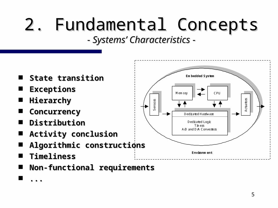
State transitionState transition ExceptionsExceptions HierarchyHierarchy ConcurrencyConcurrency DistributionDistribution Activity conclusionActivity conclusion Algorithmic constructionsAlgorithmic constructions TimelinessTimeliness Non-functional requirementsNon-functional requirements ......
Memory CPU
Sen
sors
Act
uato
rs
Embedded System
Dedicated Hardware
Dedicated LogicTimers
A/D and D/A Converters
Environment
6
2. 2. Fundamental ConceptsFundamental Concepts- HW/SW Co-Design- HW/SW Co-Design - -
AnalogInterface
Memory
Cost
Performance
SOFTWARE
HARDWARE
BehaviouralSpecification
+Restrictions
restrictions
mixedimplementation
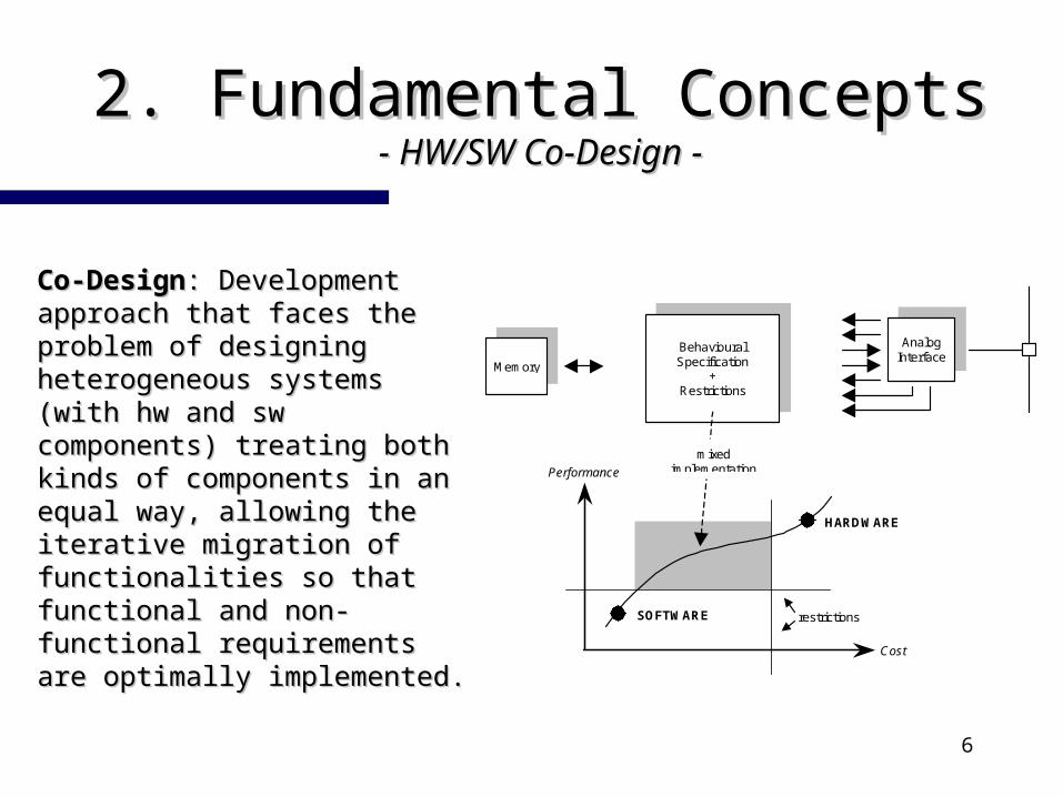
Co-DesignCo-Design: Development : Development approach that faces the approach that faces the problem of designing problem of designing heterogeneous systems heterogeneous systems (with hw and sw (with hw and sw components) treating both components) treating both kinds of components in an kinds of components in an equal way, allowing the equal way, allowing the iterative migration of iterative migration of functionalities so that functionalities so that functional and non-functional and non-functional requirements are functional requirements are optimally implemented. optimally implemented.
7
2. 2. Fundamental ConceptsFundamental Concepts- HW/SW Co-Design- HW/SW Co-Design - -
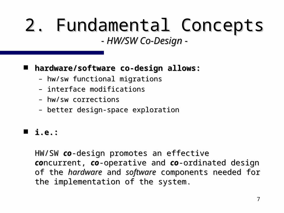
hardware/software co-design allows:hardware/software co-design allows:– hw/sw functional migrationshw/sw functional migrations– interface modificationsinterface modifications– hw/sw correctionshw/sw corrections– better design-space explorationbetter design-space exploration
i.e.:i.e.:
HW/SW HW/SW coco-design promotes an effective -design promotes an effective coconcurrent, ncurrent, coco--operative and operative and coco-ordinated design of the -ordinated design of the hardwarehardware and and softwaresoftware components needed for the implementation of components needed for the implementation of the system.the system.
8
2. 2. Fundamental ConceptsFundamental Concepts- Virtual Prototyping- Virtual Prototyping - -
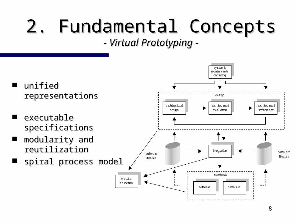
unified representations unified representations
executable specificationsexecutable specifications
modularity and modularity and reutilizationreutilization
spiral process modelspiral process model
sy stem’srequirements
capturing
architectural
design
architectural
ev aluation
design
architectural
ref inement
integration
metrics
collection
sof tware
libraries
hardware
libraries
sof tware hardware
sy nthesis
9
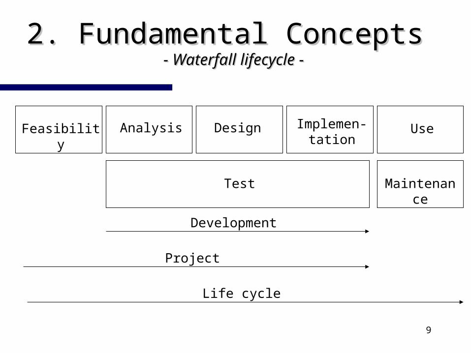
2. 2. Fundamental ConceptsFundamental Concepts - - Waterfall lifecycle Waterfall lifecycle --
Feasibility Analysis Design Implemen-tation
Use
MaintenanceTest
Development
Project
Life cycle
10
2. 2. Fundamental ConceptsFundamental Concepts - - UML Notation UML Notation --
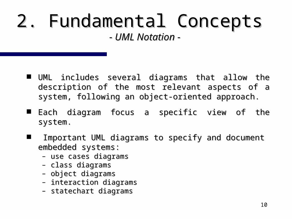
UML includes several diagrams that allow the UML includes several diagrams that allow the description of the most relevant aspects of a system, description of the most relevant aspects of a system, following an object-oriented approach. following an object-oriented approach.
Each diagram focus a specific view of the system.Each diagram focus a specific view of the system.
Important UML diagrams to specify and document Important UML diagrams to specify and document embedded systems:embedded systems:– use cases diagramsuse cases diagrams– class diagramsclass diagrams– object diagramsobject diagrams– interaction diagramsinteraction diagrams– statechart diagramsstatechart diagrams
11
2. 2. Fundamental ConceptsFundamental Concepts - - UML UML DiagramsDiagrams --
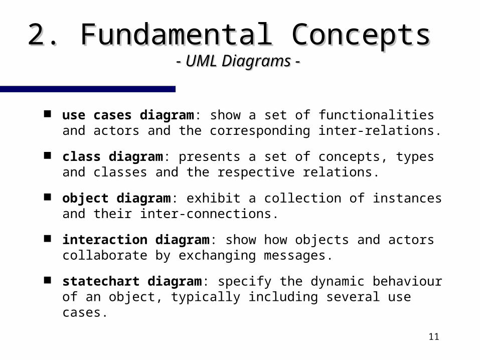
use cases diagram: show a set of functionalities and actors and the corresponding inter-relations.
class diagram: presents a set of concepts, types and classes and the respective relations.
object diagram: exhibit a collection of instances and their inter-connections.
interaction diagram: show how objects and actors collaborate by exchanging messages.
statechart diagram: specify the dynamic behaviour of an object, typically including several use cases.
12
3. 3. Analysis IssuesAnalysis Issues- Process Model- Process Model - -
An
aly
sis
7. protocol modelling
13. comparison
valid
non v
alid
3. description
Design
Viability Studies
11. specification
10. classification
4. transformation
6. behaviouralmodelling
5. data path/plantmodelling
8. selection
2. functional modelling
1. environment capturing
9. controloformalization
ContextDiagrams
Use CaseDiagrams
Textual Descriptionsof Use Cases
ClassDiagrams
ObjectDiagrams
Data Path/PlantSpecification
Sequence andScenary
Diagrams
Specification ofData Path/Plant
Using
Oblog RepositorySequenceDiagrams
Control Cycle inshobi-PN v2.0
Implementation
12. simulation
user's
requirem
ents
syste
m's
requirem
ents
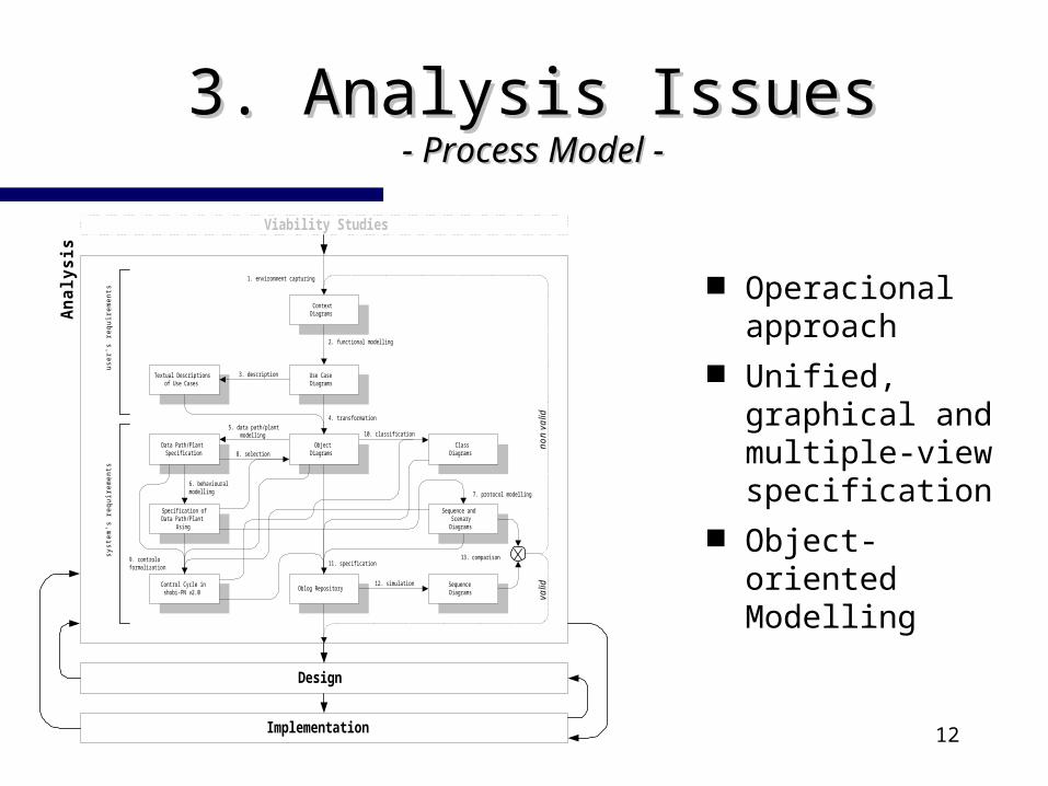
Operacional approach
Unified, graphical and multiple-view specification
Object-oriented Modelling
13
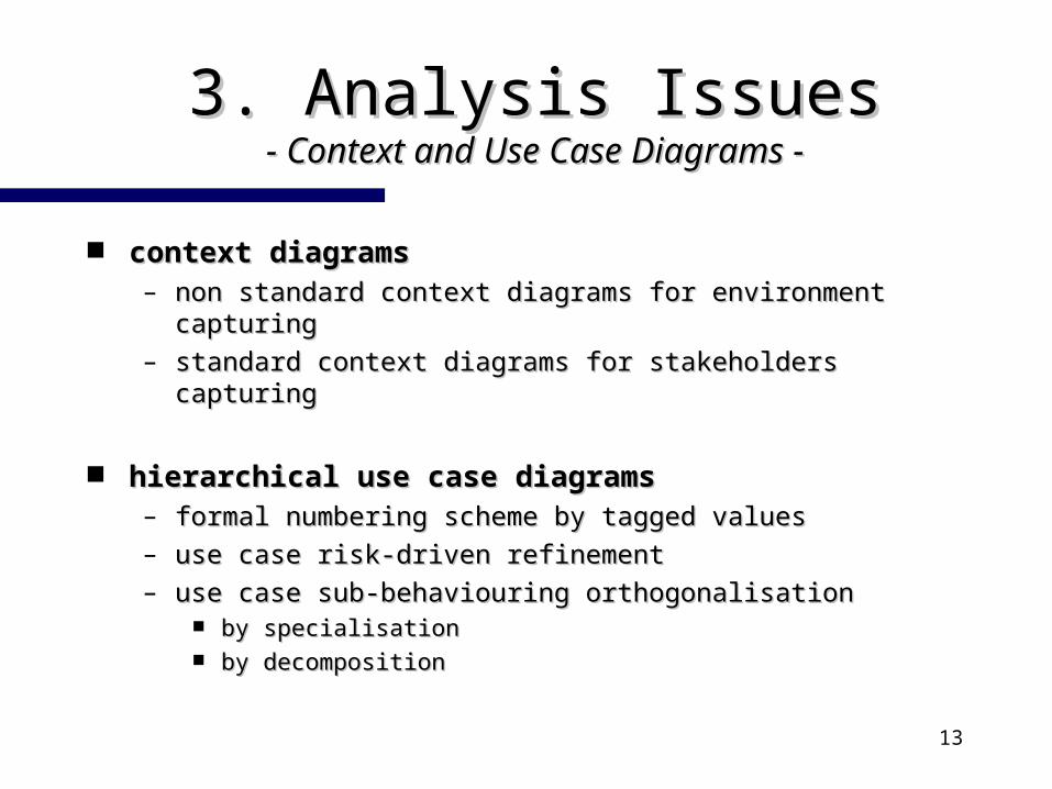
3. 3. Analysis IssuesAnalysis Issues- Context and Use Case Diagrams- Context and Use Case Diagrams - -
context diagramscontext diagrams– non standard context diagrams for environment capturingnon standard context diagrams for environment capturing– standard context diagrams for stakeholders capturingstandard context diagrams for stakeholders capturing
hierarchical use case diagramshierarchical use case diagrams– formal numbering scheme by tagged valuesformal numbering scheme by tagged values– use case risk-driven refinementuse case risk-driven refinement– use case sub-behaviouring orthogonalisationuse case sub-behaviouring orthogonalisation
by specialisationby specialisation by decompositionby decomposition
14
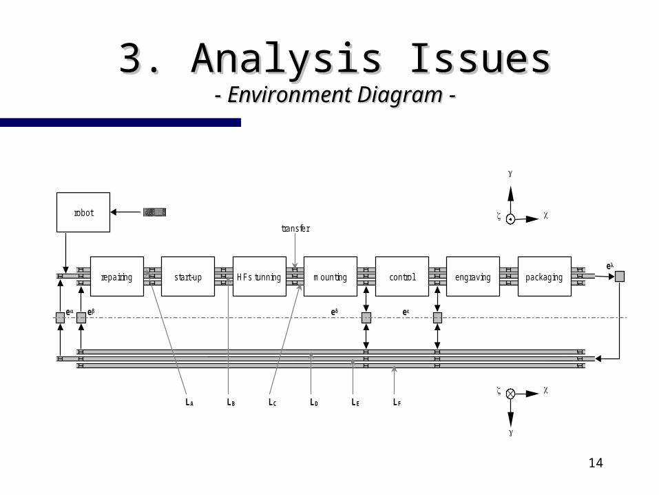
3. 3. Analysis IssuesAnalysis Issues- Environment Diagram- Environment Diagram - -
HFs tunningrepairing start-up mounting control engraving packaging
robot
LA LB LC LD LE LF
e e e e
e
transfer
15
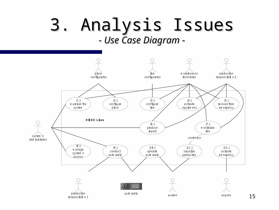
3. 3. Analysis IssuesAnalysis Issues- Use Case Diagram- Use Case Diagram - -
{6.}produce
report
HIDRO Lines
worker
{10.}operate
auto-radio
productionresponsible n.2
system 'sadm inistrator
m aintenancetechnician
lineconfigurator
placeconfigurator
anyone
{8.}m anagesystem 'saccess
{2.}configure
place
{11.}visualize
production
{12.}activate
em ergency
«extends»
productionresponsible n.1
{1.}m aintain the
system
{3.}configure
line
{4.}activate
equipm ent
{7.}m onitorize
line
{5.}recover fromem ergency
{9.}conduct
auto-radio
auto-radio
16
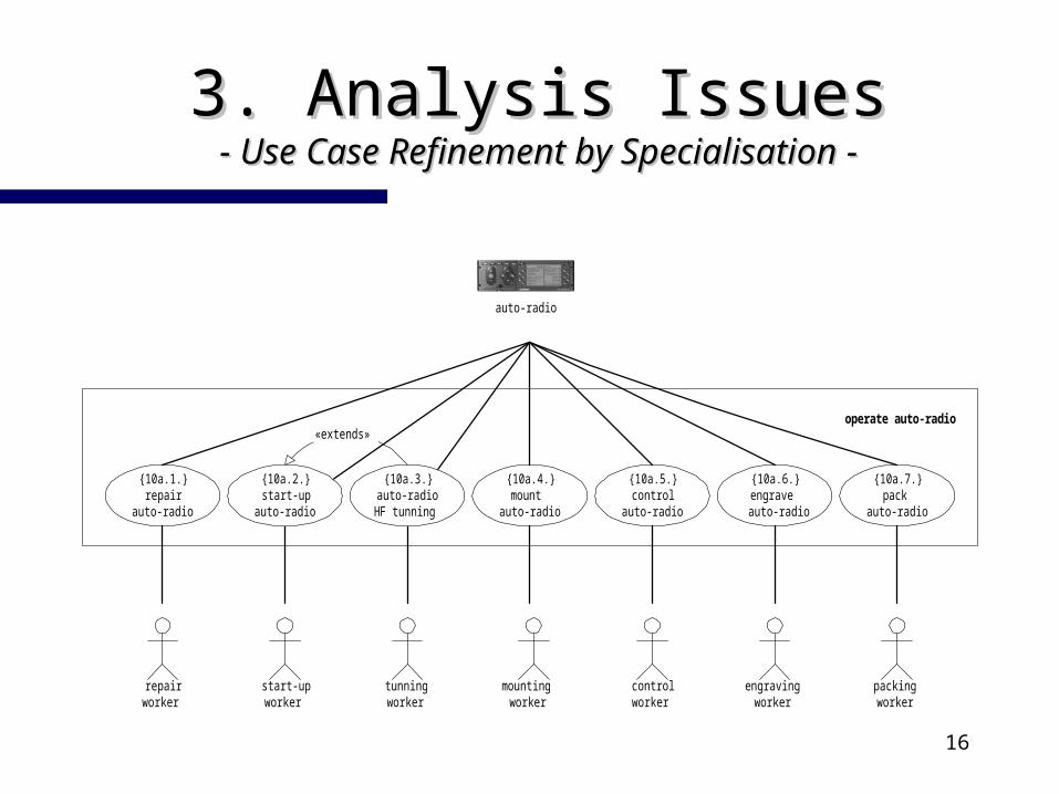
3. 3. Analysis IssuesAnalysis Issues- Use Case Refinement by Specialisation- Use Case Refinement by Specialisation - -
repairworker
packingworker
controlworker
tunningworker
start-upworker
{10a.1.}repair
auto-radio
{10a.4.}mount
auto-radio
{10a.5.}control
auto-radio
{10a.6.}engrave
auto-radio
{10a.7.}pack
auto-radio
operate auto-radio
mountingworker
engravingworker
«extends»
{10a.2.}start-up
auto-radio
{10a.3.}auto-radioHF tunning
auto-radio
17
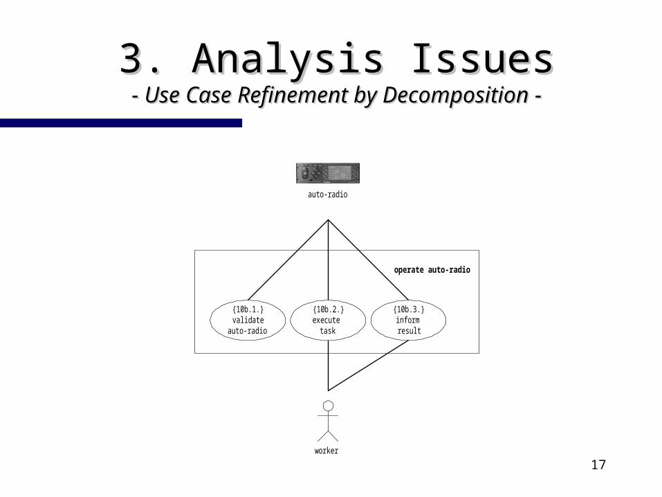
3. 3. Analysis IssuesAnalysis Issues- Use Case Refinement by Decomposition- Use Case Refinement by Decomposition - -
worker
{10b.1.}validate
auto-radio
operate auto-radio
{10b.2.}execute
task
{10b.3.}informresult
auto-radio
18
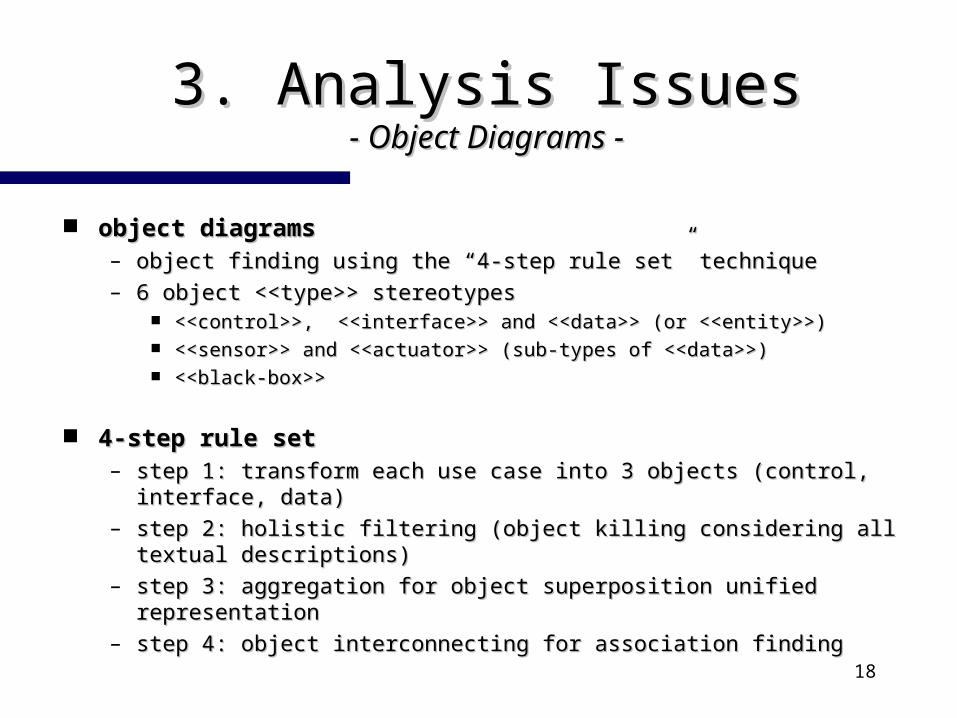
3. 3. Analysis IssuesAnalysis Issues- Object Diagrams- Object Diagrams - -
object diagramsobject diagrams– object finding using the “4-step rule set” techniqueobject finding using the “4-step rule set” technique– 6 object <<type>> stereotypes6 object <<type>> stereotypes
<<control>>, <<interface>> and <<data>> (or <<entity>>)<<control>>, <<interface>> and <<data>> (or <<entity>>) <<sensor>> and <<actuator>> (sub-types of <<data>>)<<sensor>> and <<actuator>> (sub-types of <<data>>) <<black-box>><<black-box>>
4-step rule set4-step rule set– step 1: transform each use case into 3 objects (control, interface, step 1: transform each use case into 3 objects (control, interface,
data)data)– step 2: holistic filtering (object killing considering all textual step 2: holistic filtering (object killing considering all textual
descriptions)descriptions)– step 3: aggregation for object superposition unified representationstep 3: aggregation for object superposition unified representation– step 4: object interconnecting for association findingstep 4: object interconnecting for association finding
19
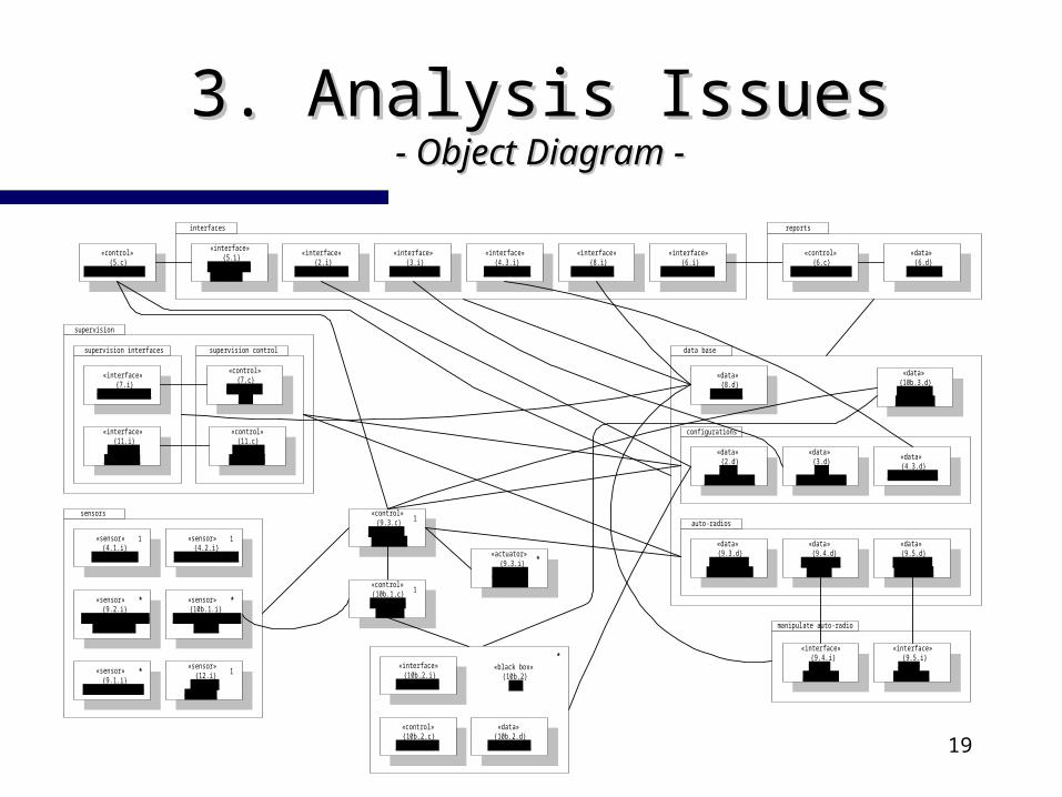
3. 3. Analysis IssuesAnalysis Issues- Object Diagram- Object Diagram - -
«data»{8.d}
passwords
«data»{10b.3.d}
resultadosdas tarefas
data base
«data»{9.3.d}
auto-radiosin production
«data»{9.5.d}
auto-rádiossolicitados
«data» {9.4.d}
auto-radioshandled
auto-radios
«data»{2.d}place
configurations
«data»{4.3.d}
postos activos
«data»{3.d}line
configurations
configurations
supervision
«interface»{11.i}
visualizeproduction
«interface»{7.i}
monitorize line
supervision interfaces
«control»{11.c}
visualizeproduction
«control»{7.c}
monitorizeline
supervision control
«control»{5.c}
emergency recover
manipulate auto-radio
sensors
«sensor»{4.2.i}
activate transport
1«sensor»{4.1.i}
activate line
1
«sensor»{12.i}
activateemergency
1«sensor»{9.1.i}
detect auto-radio
*
«sensor»{9.2.i}
identify auto-radioin transport
* «sensor»{10b.1.i}
identify auto-radioin site
*
«actuator»{9.3.i}
transporteauto-radio
*
«control»{9.3.c}
conductioncontroller
1
«interface»{6.i}
produce reports
«interface»{8.i}
manage acess
«interface»{4.3.i}
activate site
«interface»{3.i}
configure line
«interface»{2.i}
configure place
«interface»{5.i}
recover fromemergency
interfaces
«control»{6.c}
reports generator
«data»{6.d}
relatórios
reports
«control»{10b.1.c}
auto-radioverifier
1
«interface»{10b.2.i}
execute task
«control»{10b.2.c}
execute task
«data»{10b.2.d}
execute task
«black box»{10b.2}
site
*«interface»
{9.4.i}handle
auto-radio
«interface»{9.5.i}
demandconduction

20
3. 3. Analysis IssuesAnalysis Issues- Sequence Diagrams- Sequence Diagrams - -
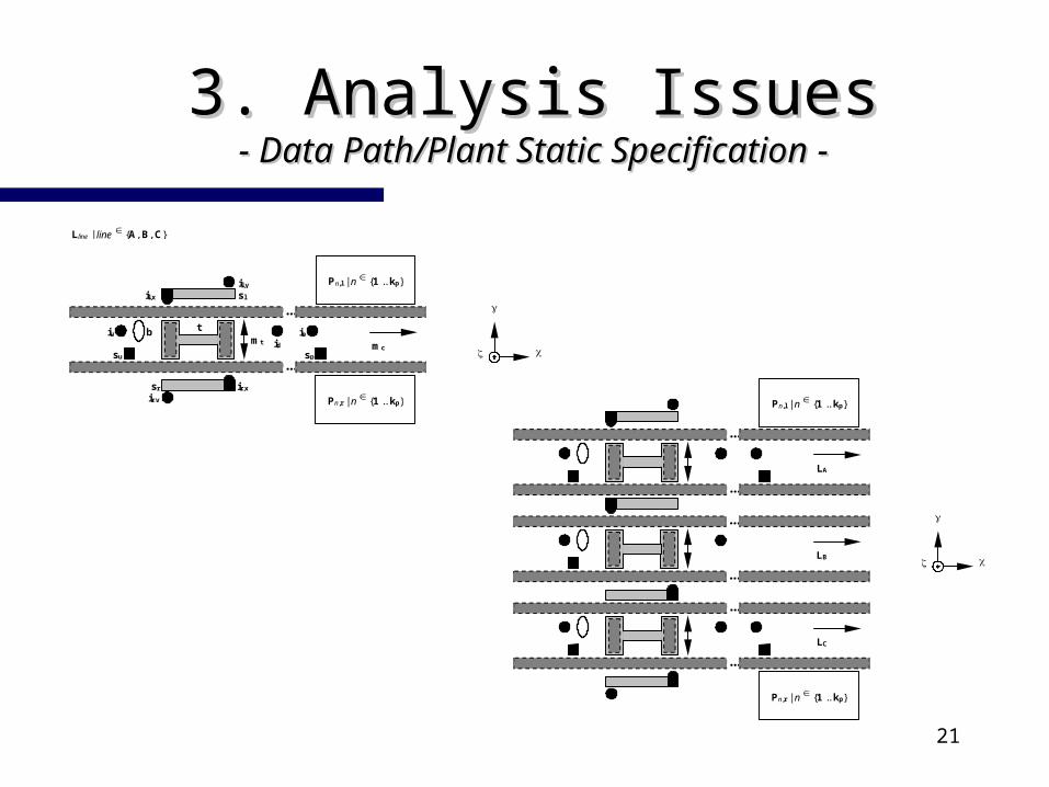
non standard data path/plant diagramsnon standard data path/plant diagrams– data path/plant’s resources static specificationdata path/plant’s resources static specification– UML does not define any diagram for thatUML does not define any diagram for that
extended sequence diagramsextended sequence diagrams– timing inscriptionstiming inscriptions
non standard scenery diagramsnon standard scenery diagrams– sequence diagrams with pictorial objectssequence diagrams with pictorial objects
21
3. 3. Analysis IssuesAnalysis Issues- Data Path/Plant Static Specification- Data Path/Plant Static Specification - -
mc
...
...
Pn,l | n {1 .. kp}
mt idip
spsu
iu b t
ir,xsr
slil,x
Lline | line {A, B, C}
Pn,r | n {1 .. kp}
il,y
ir,y
LA
...
...
Pn,l | n {1 .. kp}
LC
...
...
Pn,r | n {1 .. kp}
LB
...
...
22
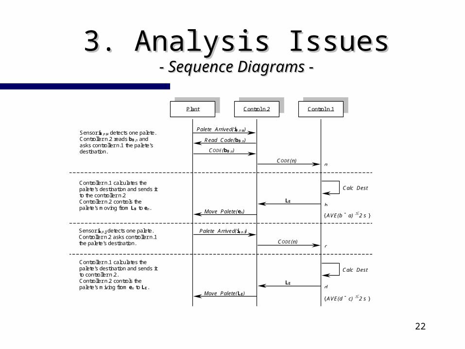
3. 3. Analysis IssuesAnalysis Issues- Sequence Diagrams- Sequence Diagrams - -
Plant Control n.2 Control n.1
Palete_Arrived(iB,n,u)
CODE(bB,n)
CODE(n)
Read_Code(bB,n)
Calc_Dest
Move_Palete(en)
LE
Sensor iB,n,u detects one palete.Controller n.2 reads bB,n andasks controller n.1 the palete’sdestination.
Controller n.1 calculates thepalete’s destination and sends itto the controller n.2Controller n.2 controls thepalete’s moving from LB to en.
CODE(n)
{ AVE(b a) 2 s }
a
b
Palete_Arrived(ie,n,j)
Calc_Dest
Move_Palete(LE)
LE
Sensor ie,n,j detects one palete.Controller n.2 asks controller n.1the palete’s destination.
Controller n.1 calculates thepalete’s destination and sends itto controller n.2.Controller n.2 controls thepalete’s miving from en to LE.
c
d
{ AVE(d c) 2 s }
23
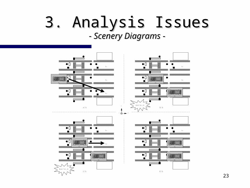
3. 3. Analysis IssuesAnalysis Issues- Scenery Diagrams- Scenery Diagrams - -
L A
. . .
. . .
L C
. . .
. . .
L B
. . .
. . .
# 1
L A
. . .
. . .
L C
. . .
. . .
L B
. . .
. . .
# 1
L A
. . .
. . .
L C
. . .
. . .
L B
. . .
. . .
# 1
L A
. . .
. . .
L C
. . .
. . .
L B
. . .
. . .
s t a r t T I M E _ B L
f i n i s h T I M E _ B L
a ) t 1 b ) t 2
c ) t 3 d ) t 4
# 2
# 2
# 1
# 2
24
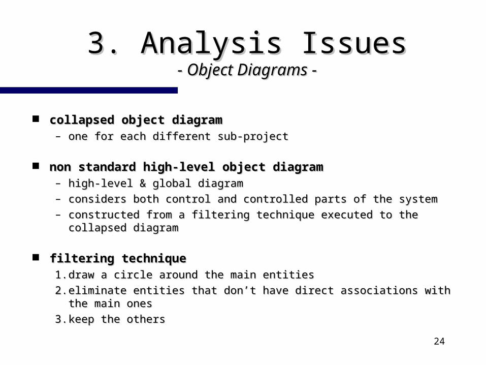
3. 3. Analysis IssuesAnalysis Issues- Object Diagrams- Object Diagrams - -
collapsed object diagramcollapsed object diagram– one for each different sub-projectone for each different sub-project
non standard high-level object diagramnon standard high-level object diagram– high-level & global diagramhigh-level & global diagram– considers both control and controlled parts of the systemconsiders both control and controlled parts of the system– constructed from a filtering technique executed to the collapsed constructed from a filtering technique executed to the collapsed
diagramdiagram
filtering techniquefiltering technique1.1. draw a circle around the main entitiesdraw a circle around the main entities
2.2. eliminate entities that don’t have direct associations with the main eliminate entities that don’t have direct associations with the main onesones
3.3. keep the otherskeep the others
25
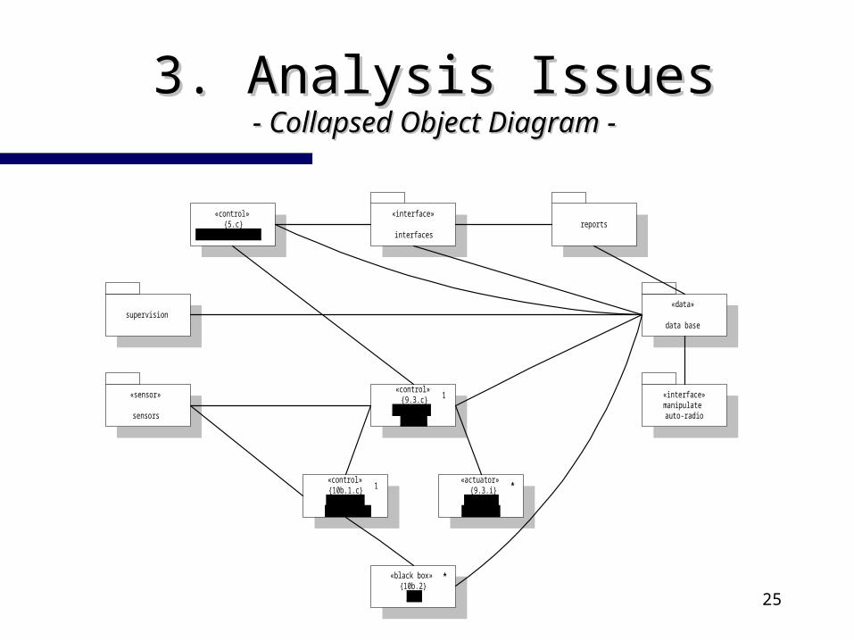
3. 3. Analysis IssuesAnalysis Issues- Collapsed Object Diagram- Collapsed Object Diagram - -
«control»{5.c}
emergency recoverreports
«interface»manipulateauto-radio
supervision
«sensor»
sensors
«control»{10b.1.c}
auto-radioveriifcation
1«actuator»
{9.3.i}transport
auto-radio
*
«control»{9.3.c}
conductioncontrol
1
«interface»
interfaces
«data»
data base
«black box»{10b.2}
site
*

26
3. 3. Analysis IssuesAnalysis Issues- Filtering the Collapsed Object Diagram- Filtering the Collapsed Object Diagram - -
«control»{5.c}
emergency recoverreports
«interface»manipulateauto-radio
supervision
«sensor»
sensors
«control»{10b.1.c}
auto-radioveriifcation
1«actuator»
{9.3.i}transport
auto-radio
*
«control»{9.3.c}
conductioncontrol
1
«interface»
interfaces
«data»
data base
«black box»{10b.2}
site
*
27
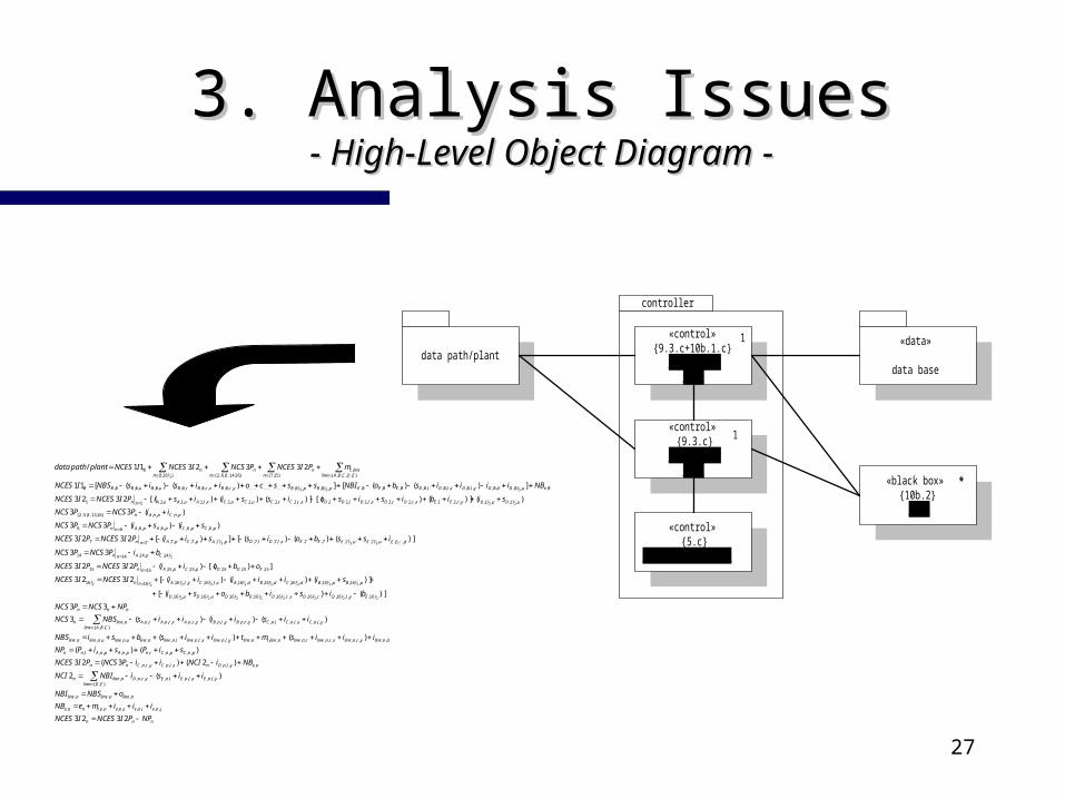
3. 3. Analysis IssuesAnalysis Issues- High-Level Object Diagram- High-Level Object Diagram - -
«control»{5.c}
emetgency recover
«control»{9.3.c+10b.1.c}
controllern. 1
1
«black box»{10b.2}
site
*
«control»{9.3.c}
controllern. 2
controller
data path/plant«data»
data base
1
nnn
jneinesnenetnne
nlinenlinenline
ylnExlnElnEyrnDEDline
nlinen
neylnDnxlnCyrnCnn
pnCpnCrnpnApnAlnn
dnlineyrnlinexrnlinernlinenlinetnlineylnlinexlnlinelnlinenlineunlineunlinenline
ylnCxlnClnCyrnBylnByrnAxrnArnACBAline
nlinen
nnn
EylDrDxrDDDuDuD
pBpBdCdBdAxlCylAnn
EDDpCpAnn
CpAnn
dEuEuEEExlDlDpApCpAnn
pCpCpApAnn
pnCpnAn
uDuDyrEExrDrDxlDlDDxrCrCuCuCxlAuAuAnn
euDdDylDxlDlDEEEpBpByrBxrBrBuBuBB
EDCBAlinelinec
nn
nn
nn
NPPINCESINCES
iiimeNB
oNBSNBI
iisiNBINCI
NBiNCIiiPNCSPINCES
siPsiPNP
iiismtiisbsiNBS
iisiiiisNBSNCS
NPNCSPNCS
bisibosi
siiiiiiINCESINCES
oboiiPINCESPINCES
biPNCSPNCS
issboissiiPINCESPINCES
sisiPNCSPNCS
iiPNCSPNCS
siibisisoissiisiPINCESINCES
NBiiiisboNBIssscoiisisNBSINCES
mPINCESPNCSINCESINCESplantpathdata
2323
)(2
)2()3(23
)()(
)()(
)()()(3
33
)]()([
)]()()([2323
])[()(2323
33
)]()()([])([2323
)()(33
)(33
)()]()[()]()()[(2323
])()([])()([11
2332311/
,,,,,,,,,
,,,
,,,,,,,,,,,},{
,
,,,,,,,,,,
,,,,,,,,,,
,,,,,,,,,,,,,,,,,,,,,,,,,,,
,,,,,,,,,,,,,,,,,,,,,,},,{
,
16,,,16,,16,,,16,16,16,,16,,16,
,16,,16,,16,,16,,16,,,16,,,16,1616
15,15,15,,15,,15,1515
14,,14,1414
,6,,7,,7,7,7,,,7,,7,,7,,7,,7,77
,6,,6,,6,,6,66
,,,,}16,13..8,5..2{
,1,,1,,,1,1,,,1,,1,,,1,,1,1,,,1,,1,,1,,1,,,1,,1,,1,11
0,,0,,0,,,0,,,0,,0,0,0,0,,0,,0,.........,,0,,,0,,0,,0,,0,0,0
},,,,{,
}15,7{}16,14..8,6..2{}16,1{0
21
21
21
21
21
21
21
21
21
21
21
21
21
21
21
212
1
21
......
32
31
31
21
21
32
32
31
21
28
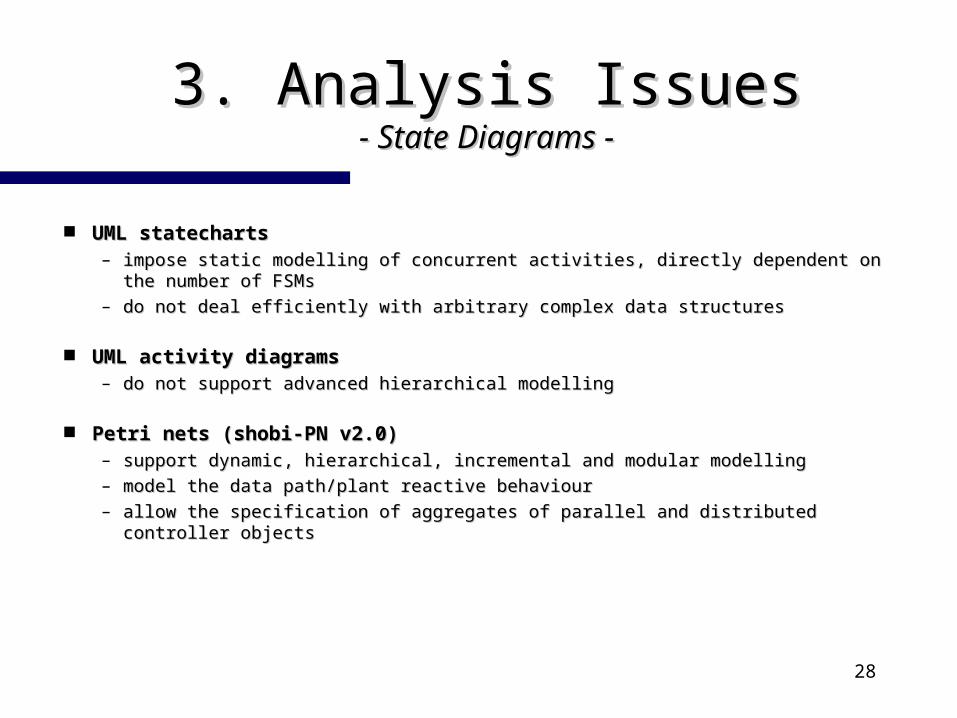
3. 3. Analysis IssuesAnalysis Issues- State Diagrams- State Diagrams - -
UML statechartsUML statecharts– impose static modelling of concurrent activities, directly dependent on the impose static modelling of concurrent activities, directly dependent on the
number of FSMsnumber of FSMs– do not deal efficiently with arbitrary complex data structuresdo not deal efficiently with arbitrary complex data structures
UML activity diagramsUML activity diagrams– do not support advanced hierarchical modellingdo not support advanced hierarchical modelling
Petri nets (shobi-PN v2.0)Petri nets (shobi-PN v2.0)– support dynamic, hierarchical, incremental and modular modellingsupport dynamic, hierarchical, incremental and modular modelling– model the data path/plant reactive behaviourmodel the data path/plant reactive behaviour– allow the specification of aggregates of parallel and distributed controller objectsallow the specification of aggregates of parallel and distributed controller objects
29
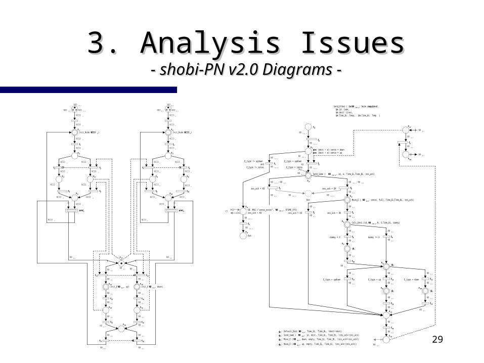
3. 3. Analysis IssuesAnalysis Issues- shobi-PN v2.0 Diagrams- shobi-PN v2.0 Diagrams - -
NCS3 n
NCS3 n
Init_Node ( NCS3 n)
NBS A ,n
NBS C ,nNBS B ,n
NCS3 n
NCS3 n
NCS3 nNCS3 n
NCS3 n NCS3 n
NCS3 nNCS3 n
NCS3 n
NCS3 nNCS3 n
NCI3 n
NCI3 n
Init_Node ( NCI3 n)
NBI D ,n
NBI F ,nNBI E ,n
NCI3 n
NCI3 n
NCI3 nNCI3 n
NCI3 n NCI3 n
NCI3 nNCI3 n
NCI3 n
NCI3 nNCI3 n
NB e ,nNB e ,nNB e ,n
NB e ,n
NB e ,n
NB e ,n
NB e ,n
NB e ,n
NB e ,n
NB e ,n
Init_E ( NB e ,n , up)
NB e ,n
NB e ,n
NB e ,n
NB e ,n
Init_E ( NB e ,n , down)
NB e ,n
NB e ,n NB e ,n
NB e ,nNB e ,n
NCI3 nNCS3 n
s1
s2
s3 s4
s5
s7
s8 s9
s10
s6
s11
s12 s13
s14 s15
s16
t1
t3t2
t4 t5
amt 1
t6
t8t7
t9 t10
amt 2
t12t11
t13 t14
t15 t16
t17 t18
* 1 : Default_Dest ( NB e ,n , Time_GL, Time_BL, !dest>>dest)
Ret
res_ack = OK
NB line ,n
NB line ,n
res_ack = KO
Send_Same ( NB l ine ,n , id, e, Time_GL, Time_BL, res_ack)
* 2 : Send_Same ( NB e,n , id, dest, Time_GL, Time_BL, !res_ack>>res_ack)
* 3 : Move_E ( NB e ,n , down, empty, Time_GL, Time_BL, !res_ack>>res_ack1)
NB e ,n
NB e ,n
Move_E ( NB e,n , sense, full, Time_GL, Time_BL, res_ack)
res_ack = OK
Calc_Dest (id, NB line ,n .N, 3, Time_BL, dummy)
dummy = X dummy != X
NB e ,n
NB e ,n
E_type = updown E_type = downE_type = up
* 2
* 1
* 3 * 4
NB line ,n+NB e ,nNB line ,n+NB e ,n
NB e,n
NB e ,nNB e ,n
NB e ,nNB e ,n
NB e,nNB e ,n
NB e,nNB e ,n
NB e ,n
NB e,nNB e ,n
NB e,n
NB e ,n NB e,n
NB e,n
NB e,n
NB e,n
NB e,n
NB e,n
NB e,n
* 4 : Move_E ( NB e ,n , up, empty, Time_GL, Time_BL, !res_ack>>res_ack1)
Send_Other ( in NB line ,n : Node require d ,in id: Code,in dest: Lines,in Time_GL: Temp, in Time_BL: Temp )
NB e ,n
NB e ,n
NB e ,n
pre (dest > e) sense = downpre (dest < e) sense = up
NB line ,n
NB e ,n
NB e,n
NB line ,n
E_type = updownor
E_type = sense
E_type != updownand
E_type != sense
NB line ,n
NB line ,nNB line ,n
NB line ,n
NB line ,n
NB line ,n
C1 .MSG ("sense_error", NB l ine ,n , $TIME_SYS)res_ack = KO res_ack = KO
C1
sei
seo
te
Ret
t2
s2
s1
s0
t0
t1
t3 t4
t5 t6
t7
t8 t9
t10
t11 t12 t13
t14 t15
t16
s3
s4
s6
s5
s7
s8
s9 s10
s11
s12
30
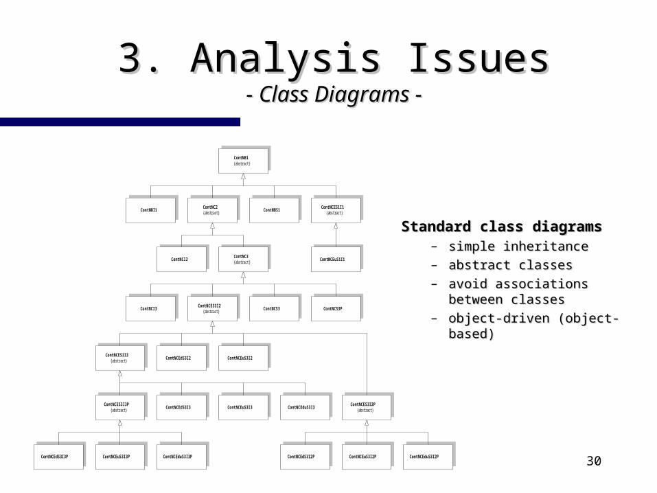
3. 3. Analysis IssuesAnalysis Issues- Class Diagrams -- Class Diagrams -
Standard class diagramsStandard class diagrams– simple inheritancesimple inheritance– abstract classesabstract classes– avoid associations between avoid associations between
classesclasses– object-driven (object-object-driven (object-
based)based)
ContNCES1I1{abstract}
ContNCS3PContNCES3I2{abstract}
ContNCEuS3I2ContNCEdS3I2ContNCES3I3{abstract}
ContNCES3I2P{abstract}
ContNCEduS3I2PContNCEuS3I2PContNCEdS3I2P
ContNCEduS3I3ContNCEuS3I3ContNCEdS3I3ContNCES3I3P
{abstract}
ContNCEduS3I3PContNCEuS3I3PContNCEdS3I3P
ContNC2{abstract}
ContNB1{abstract}
ContNBS1
ContNC3{abstract}
ContNCS3
ContNCI2
ContNBI1
ContNCI3
ContNCEuS1I1
31
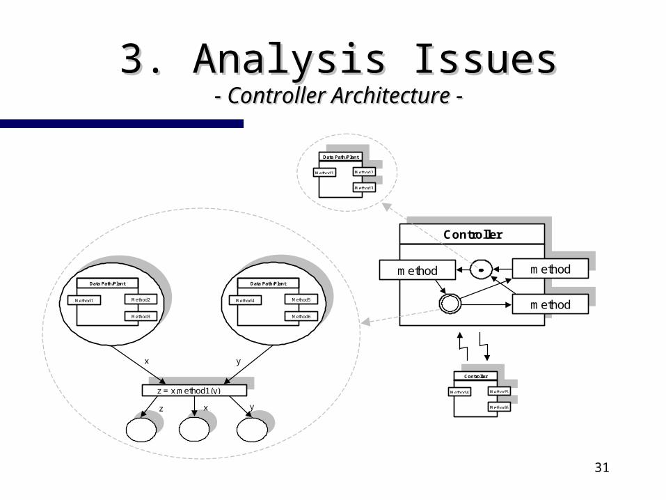
3. 3. Analysis IssuesAnalysis Issues- Controller Architecture -- Controller Architecture -
Method4
Controller
Method6
Method5
method
Controller
method
method
Method1
Data Path/Plant
Method3
Method2
Method4
Data Path/Plant
Method6
Method5Method1
Data Path/Plant
Method3
Method2
z = x.method1(y)
x y
yxz
32
3. 3. Analysis IssuesAnalysis Issues- OBLOG Generation -- OBLOG Generation -
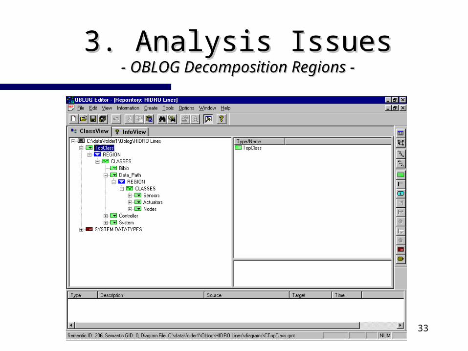
3 decomposition regions3 decomposition regions– data pathdata path
sub-region sub-region sensorssensors sub-region sub-region actuatorsactuators sub-region sub-region nodesnodes
– controllercontroller specifies the aggregates of state-machinesspecifies the aggregates of state-machines
– system system specifies the final system to be implementedspecifies the final system to be implemented
33
3. 3. Analysis IssuesAnalysis Issues- OBLOG Decomposition Regions -- OBLOG Decomposition Regions -
34
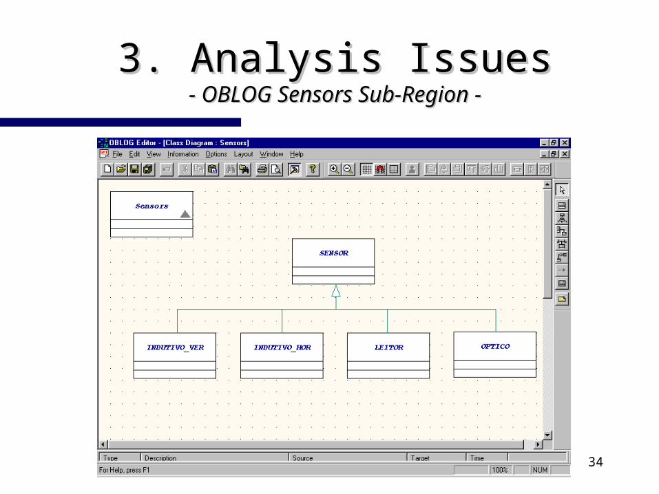
3. 3. Analysis IssuesAnalysis Issues- OBLOG Sensors Sub-Region -- OBLOG Sensors Sub-Region -
35
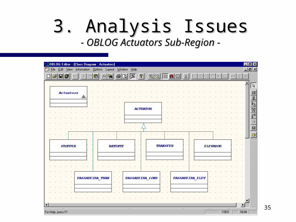
3. 3. Analysis IssuesAnalysis Issues- OBLOG Actuators Sub-Region -- OBLOG Actuators Sub-Region -
36
3. 3. Analysis IssuesAnalysis Issues- OBLOG Generation -- OBLOG Generation -
special attention must be paid to the following issuesspecial attention must be paid to the following issues– state state Oblog is not state oriented Oblog is not state oriented– synchronism synchronism Oblog is inherently asynchronous Oblog is inherently asynchronous– hierarchy hierarchy Oblog does not directly support structural hierarchies Oblog does not directly support structural hierarchies
3 sets of rules have been defined to allow the generation 3 sets of rules have been defined to allow the generation of Oblog to specify parallel controllersof Oblog to specify parallel controllers1) rule-set for the definition of an abstract class of parallel controllers1) rule-set for the definition of an abstract class of parallel controllers
2) rule-set for emulating state orientation2) rule-set for emulating state orientation
3) rule-set for the construction of a collection of sub-machines3) rule-set for the construction of a collection of sub-machines
37
3. 3. Analysis IssuesAnalysis Issues- OBLOG Generation -- OBLOG Generation -
rule-set for emulating state orientationrule-set for emulating state orientation– state change methods (Oblog self initiative operations)state change methods (Oblog self initiative operations)– event reaction oriented transition methods (event reaction operations)event reaction oriented transition methods (event reaction operations)– eventless transition methods (event reaction operations)eventless transition methods (event reaction operations)– state methodsstate methods– exception handling to handle behavioural abortionsexception handling to handle behavioural abortions
rule-set for the construction of a collection of sub-machinesrule-set for the construction of a collection of sub-machines– upper to lower level machine communication by direct invocationupper to lower level machine communication by direct invocation– lower to upper level machine communication bylower to upper level machine communication by
multicast sub_param (sender << “net1_s2”, param << condition_out) multicast sub_return (sender << “send_other_amt2”, ret << TRUE)
38
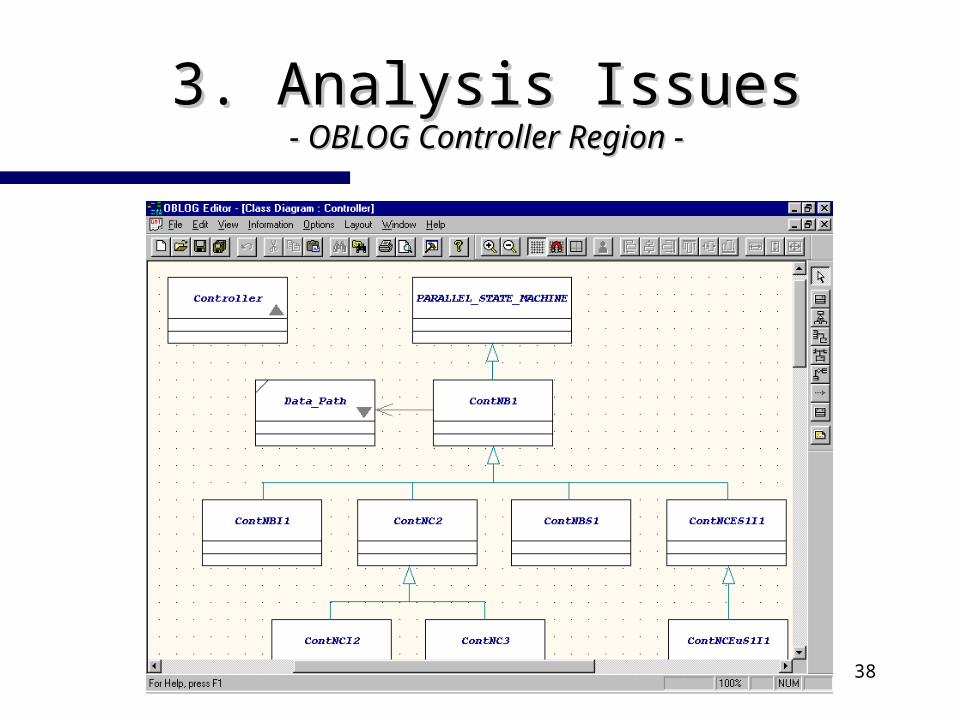
3. 3. Analysis IssuesAnalysis Issues- OBLOG Controller Region -- OBLOG Controller Region -
39
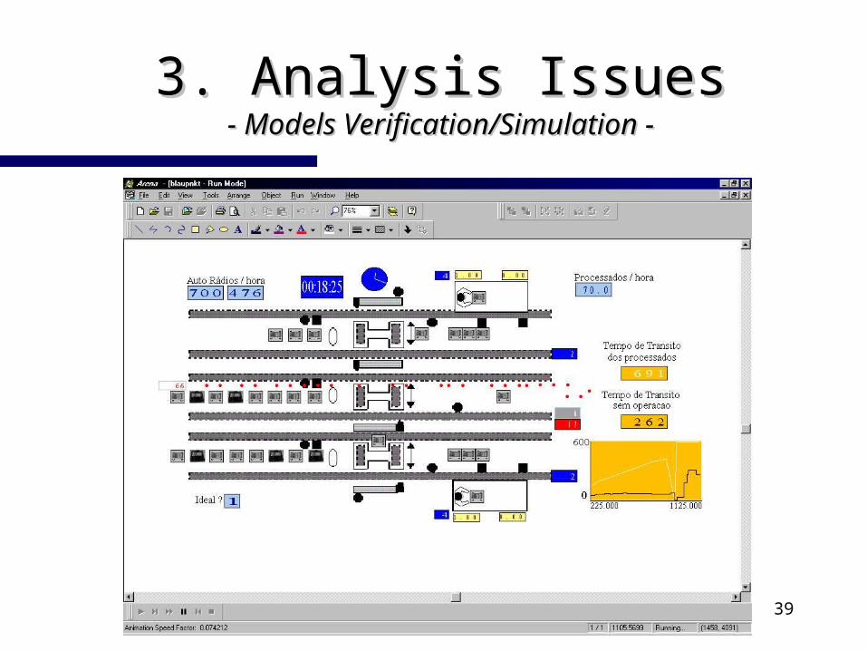
3. 3. Analysis IssuesAnalysis Issues- Models Verification/Simulation -- Models Verification/Simulation -
40
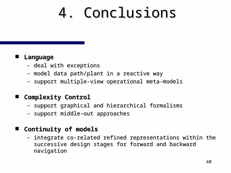
4. 4. ConclusionsConclusions
LanguageLanguage– deal with exceptionsdeal with exceptions– model data path/plant in a reactive waymodel data path/plant in a reactive way– support multiple-view operational meta-modelssupport multiple-view operational meta-models
Complexity ControlComplexity Control– support graphical and hierarchical formalismssupport graphical and hierarchical formalisms– support middle-out approachessupport middle-out approaches
Continuity of modelsContinuity of models– integrate co-related refined representations within the integrate co-related refined representations within the
successive design stages for forward and backward navigationsuccessive design stages for forward and backward navigation
41
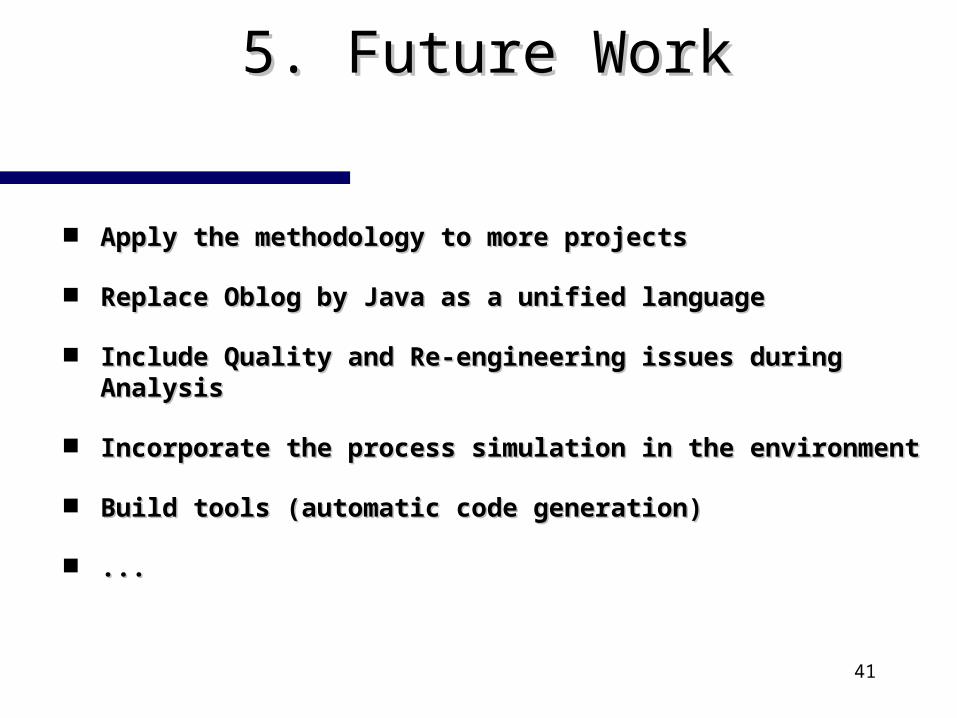
5. 5. Future WorkFuture Work
Apply the methodology to more projects Apply the methodology to more projects
Replace Oblog by Java as a unified languageReplace Oblog by Java as a unified language
Include Quality and Re-engineering issues during Include Quality and Re-engineering issues during AnalysisAnalysis
Incorporate the process simulation in the Incorporate the process simulation in the environmentenvironment
Build tools (automatic code generation)Build tools (automatic code generation)
......


![arXiv:1712.02098v1 [astro-ph.HE] 6 Dec 2017 · PDF fileBlazar spectral variability as explained by a twisting inho-mogeneous jet C. M. Raiteri1, M. Villata1, J. A. Acosta-Pulido2;3,](https://img.pdfslide.us/doc/110x75/5a781bc47f8b9a4b538e7661/arxiv171202098v1-astro-phhe-6-dec-2017-a-blazar-spectral-variability.jpg)