Embed Size (px)
Citation preview
J. Biomedical Science and Engineering, 2010, 3, 138-147 JBiSE doi:10.4236/jbise.2010.32019 Published Online February 2010 (http://www.SciRP.org/journal/jbise/).
Published Online February 2010 in SciRes. http://www.scirp.org/journal/jbise
A method to fabricate small features on scaffolds for tissue engineering via selective laser sintering S. Lohfeld1, M. A. Tyndyk1, S. Cahill1,2, N. Flaherty1, V. Barron1, P. E. McHugh1,2 1National Centre for Biomedical Engineering Science, National University of Ireland, Galway, Ireland 2Department of Mechanical and Biomedical Engineering, College of Engineering and Informatics, National University of Ireland, Galway, Ireland Email: [email protected]
Received 24 November 2009; revised 18 December 2009; accepted 21 December 2009.
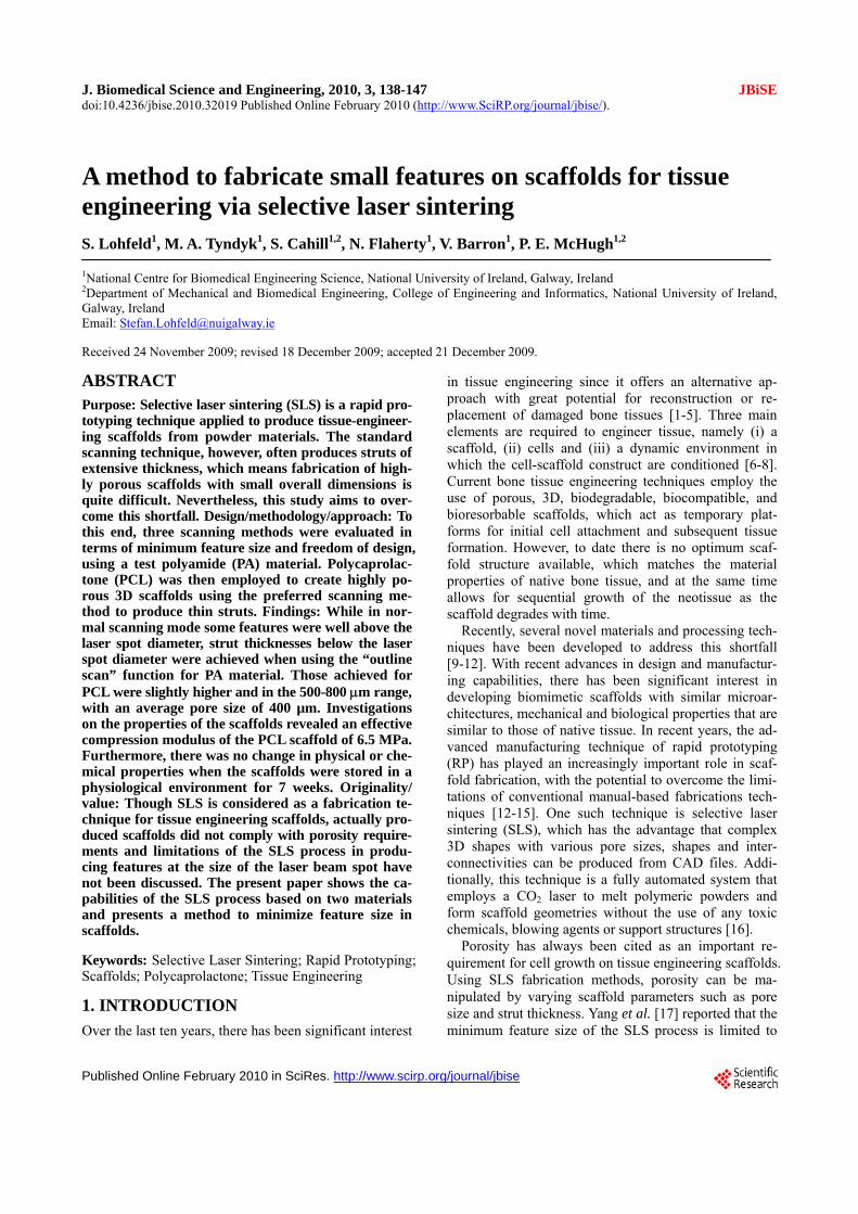
ABSTRACT Purpose: Selective laser sintering (SLS) is a rapid pro- totyping technique applied to produce tissue-engineer- ing scaffolds from powder materials. The standard scanning technique, however, often produces struts of extensive thickness, which means fabrication of high- ly porous scaffolds with small overall dimensions is quite difficult. Nevertheless, this study aims to over-come this shortfall. Design/methodology/approach: To this end, three scanning methods were evaluated in terms of minimum feature size and freedom of design, using a test polyamide (PA) material. Polycaprolac-tone (PCL) was then employed to create highly po-rous 3D scaffolds using the preferred scanning me- thod to produce thin struts. Findings: While in nor-mal scanning mode some features were well above the laser spot diameter, strut thicknesses below the laser spot diameter were achieved when using the “outline scan” function for PA material. Those achieved for PCL were slightly higher and in the 500-800 m range, with an average pore size of 400 µm. Investigations on the properties of the scaffolds revealed an effective compression modulus of the PCL scaffold of 6.5 MPa. Furthermore, there was no change in physical or che- mical properties when the scaffolds were stored in a physiological environment for 7 weeks. Originality/ value: Though SLS is considered as a fabrication te- chnique for tissue engineering scaffolds, actually pro- duced scaffolds did not comply with porosity require-ments and limitations of the SLS process in produ- cing features at the size of the laser beam spot have not been discussed. The present paper shows the ca-pabilities of the SLS process based on two materials and presents a method to minimize feature size in scaffolds.
Keywords: Selective Laser Sintering; Rapid Prototyping; Scaffolds; Polycaprolactone; Tissue Engineering
1. INTRODUCTION
Over the last ten years, there has been significant interest
in tissue engineering since it offers an alternative ap-proach with great potential for reconstruction or re-placement of damaged bone tissues [1-5]. Three main elements are required to engineer tissue, namely (i) a scaffold, (ii) cells and (iii) a dynamic environment in which the cell-scaffold construct are conditioned [6-8]. Current bone tissue engineering techniques employ the use of porous, 3D, biodegradable, biocompatible, and bioresorbable scaffolds, which act as temporary plat-forms for initial cell attachment and subsequent tissue formation. However, to date there is no optimum scaf-fold structure available, which matches the material properties of native bone tissue, and at the same time allows for sequential growth of the neotissue as the scaffold degrades with time.
Recently, several novel materials and processing tech-niques have been developed to address this shortfall [9-12]. With recent advances in design and manufactur-ing capabilities, there has been significant interest in developing biomimetic scaffolds with similar microar-chitectures, mechanical and biological properties that are similar to those of native tissue. In recent years, the ad-vanced manufacturing technique of rapid prototyping (RP) has played an increasingly important role in scaf-fold fabrication, with the potential to overcome the limi-tations of conventional manual-based fabrications tech-niques [12-15]. One such technique is selective laser sintering (SLS), which has the advantage that complex 3D shapes with various pore sizes, shapes and inter-connectivities can be produced from CAD files. Addi-tionally, this technique is a fully automated system that employs a CO2 laser to melt polymeric powders and form scaffold geometries without the use of any toxic chemicals, blowing agents or support structures [16].
Porosity has always been cited as an important re-quirement for cell growth on tissue engineering scaffolds. Using SLS fabrication methods, porosity can be ma-nipulated by varying scaffold parameters such as pore size and strut thickness. Yang et al. [17] reported that the minimum feature size of the SLS process is limited to

S. Lohfeld et al. / J. Biomedical Science and Engineering 3 (2010) 138-147
Copyright © 2010 SciRes. JBiSE
139
400 µm, which basically is due to the laser spot diameter. In this situation a requirement for high porosity, com-bined with a small pore size, necessitates the generation of a low scaffold strut thickness. However, specific de-tails about scaffold strut thickness in the literature are difficult to obtain. When strut thickness values are quoted, as for example by Das et al. [18] and Partee et al. [19], they are deemed to be multiples of the proposed laser spot diameter; at least 700 µm. Some studies concentrate on the size of the pores without giving details on the achieved strut thickness [20,21], while Smith et al. [22] gave no dimensions of the actual scaffold features at all. Other studies discussed selective laser sintering of scaf-folds, however, for the experiments simple flat disks were manufactured to investigate sintering of the mate-rial used. In these cases the pore size and shape were not the specific focus, but the porosity was generated by adjusting the process parameters [16,23]. A comparison between intended design (CAD) and actual achieved structure is often missing. Williams et al. [21] designed pores of 1.75 to 2.5 mm and calculated porosities of 63.1% to 79%, while the porosity of the fabricated scaf-folds actually achieved was consistently 27 percentage points lower than the values aimed for. This was due to particle size and growth of the struts by heat conduction into adjacent powder particles.
Strut thickness is an important consideration in SLS fabricated scaffolds to achieve high porosities with small pores. Due to the importance of being able to generate thin struts, the study presented here was focussed on an examination of the different SLS scan options with a view to generating a minimum strut thickness. With pro- cess parameters for sintering of polycaprolactone (“PCL”), determined as part of the study, scaffolds were fabricated and characterised in terms of strut morphology and me-chanical properties.
2. MATERIALS AND METHODS
2.1. SLS Processing Methods
In this study, a Sinterstation 2500plus (DTM, USA) was employed to fabricate the scaffolds. Initially, Duraform PA powder (polyamide, “PA”) (3D Systems, UK) was employed to optimise the build parameters. Thereafter, PCL (CAPA6501, Solvay, UK) was used to fabricate the scaffolds. The software “Sinter v3.3” (3D Systems) was used to prepare the builds. The Sinterstation 2500plus is actually optimised to build large models and the optics focus the CO2 laser spot to a diameter of about 400 to 500 µm. To achieve feature sizes in the appropriate range for tissue engineering scaffolds, as a first step, the laser processing parameters have to be optimised.
The main sintering path of the laser is along the x-axis of the machine, which is parallel to the front wall of the build chamber. In general, the cross sections of the 3D
models are sintered with parallel line scans in the x-direction, incrementally shifted in the y-direction (fill scan). In the y-direction, thin walls or struts are fabri-cated by single dot-like shots, building up to form a line parallel to the y-axis, as pictured in Figure 1. Ideally, a strut built this way has a thickness similar to the laser spot diameter.
Surfaces that have not been parallel to the y-axis dur-ing fabrication may appear stepped due to the scanning technique. To reduce this, a so-called “outline scan” can be added to improve the surface quality. After perform-ing the fill scan, the laser scans along the edge of the part in each cross section similar to a plotter. As laser power and offset values of both the fill scan and the out-line scan can be controlled separately, the latter can be used to fabricate thin, smooth walls in any direction in the x-y-plane by turning off the “fill scan” completely.
To compensate for the diameter of the laser spot when scanning, the laser usually is offset from the edges of the cross section. Depending on the offset value and the di-mensions of the strut in the 3D design, one or two main struts in the fabricated scaffold can be created. This will be explained further below.
In order to find the most suitable method to fabricate thin struts in scaffolds, the present paper investigated three approaches:
a) using the fill scan and a laser offset of about half of the strut thickness
b) using the outline scan, but no laser offset (laser path along the edge of the strut)
c) using the outline scan and a laser offset of about half of the strut thickness
Method a) is the common sintering technique used for all models fabricated using the Sinterstation. Therefore,
Figure 1. Build preview showing the laser scan paths. Thin lines parallel to the y direction of the build chamber consist of single laser shots aligned along the y axis.

S. Lohfeld et al. / J. Biomedical Science and Engineering 3 (2010) 138-147
Copyright © 2010 SciRes. JBiSE
140
Figure 2. Laser spot over-lap when the strut thickness t is smaller than the laser spot diameter D.
Figure 3. Designed 3D model (left) and actually built model (right).
it was investigated to examine the accuracy of the scaf-folds generated using the standard sintering technique.
Method b) fabricated a frame around the designed strut with two short and two long edges. During the de-sign stage it was taken into account that the long edges were likely to be fused together if their distance (= strut width) was less than the laser spot diameter of 410 µm. This is due to an overlap of the laser spot in the centre of the strut when scanning around the edge of the strut (Figure 2). Therefore, the strut width was set to 800 µm, and the distance between the struts was set to be the same to ensure even distances between the sintered paths. Each single strut in the 3D design actually resulted in
Figure 4. Laser scans along the centreline of each strut.
two struts connected at the ends in the fabricated scaf-fold (Figure 3). As only one pass of the laser per strut was used here, these struts were expected to have the smallest achievable dimensions. For Method c) the offset value was set to approximately half the thickness of a designed strut to make the laser scan along the centre line of each strut (Figure 4). As the outline has to be a closed line, the laser scanned along the centre line twice. It was assumed that this adds to the thickness of the final fabricated strut. On the other hand, unlike Method b), the fabricated scaffold resembled the 3D design as the actual strut thickness achieved by this method has been antici-pated in the design.
2.2. Scaffold Design Dependence of SLS Parameter settings
All scaffolds were designed using Pro/Engineer Wildfire (PTC, USA) and exported into the. STL file format. Scaffolds designed for Method a) consisted of four struts per layer, each strut 500 µm wide and with 2 mm dis-tance between the centrelines of the struts. For Method b) four struts per layer were necessary in the 3D design to result in eight struts in the fabricated model. In this case, the struts were designed with a width of 1 mm, a height of 500 µm and a centreline separation distance of 2 mm. Scaffolds designed for Method c) consisted of eight struts per layer, each 500 µm wide, with a distance of 1 mm between the strut centrelines. In all cases the layers were oriented alternating parallel to the x or to the y-axis. Three layers with a height of 500 µm each and, to dis-tinguish between top and bottom of the scaffold, a top layer of 1000 µm height, were included. CAD images of the models are illustrated in Figure 5.
The important sintering parameters can be seen in Ta-ble 1. The laser power was reduced for Methods b) and c) because the laser scan speed is slower in the “outline scan” mode. When not reducing the laser power, the energy density
LPED
SS LS
(1)

S. Lohfeld et al. / J. Biomedical Science and Engineering 3 (2010) 138-147
Copyright © 2010 SciRes. JBiSE
141
(with ED = energy density in J/mm², LP = laser power in Watt, SS = scan spacing in mm, and LS = laser scan speed in mm/s), as described in Caulfield et al. [24], would have been excessive over Method a), resulting in thicker struts.
Using the laser scan method that was found to be most suitable to fabricate thin struts, a parameter study was performed to find process parameters most suitable for sintering PCL scaffolds. The variable parameters were laser power (3.5 up to 11.5 W with 0.5 W increments),
number of scans (one or two) and preheat temperature for the powder (38℃ up to 50℃). Subsequently, cylin-drical scaffolds with diameters of 5 and 8 mm (Figure 6) were fabricated from PCL. Resulting from the parameter study, the powder bed preheat temperature was set to 38℃ and sintering was performed with a single scan at a laser power of 4 W. The scaffolds were sliced into 45 horizontal layers with a layer thickness of 0.11 mm each. Each set of struts consisted of 5 layers.
Figure 5. CAD models for scan method experiments.
Table 1. Sintering parameters for the polyamide scaffolds.
Laser offset Fabrication method
x-direction µm y-direction µm
Laser powerW
Scan spacing mm
a) 240 200 9 0.10
b) 0 0 5 n/a
c) 243 243 5 n/a
Figure 6. CAD models for PCL scaffolds.

S. Lohfeld et al. / J. Biomedical Science and Engineering 3 (2010) 138-147
Copyright © 2010 SciRes. JBiSE
142
Figure 7. Polyamide models fabricated via the three scan methods.
Table 2. Strut width in x and y directions for each SLS fabrication method.
Strut Width Method a) Method b) Method c)
x - direction [µm] 325 +/- 8 325 +/- 21 355 +/- 20
y - direction [µm] 955 +/- 49 330 +/- 20 375 +/- 8
2.3. Characterisation of Scaffold Properties
2.3.1. Strut Morphology The scaffold structures were examined by scanning elec-tron microscopy (SEM) (Hitachi, UK). All surfaces were coated with gold using an Emitech K550 gold coater (Emitech, UK) to avoid charging under the electron beam. The pore size, pore area, and strut thickness values as well as the surface topography were obtained using Im-ageJ analysis software (NIH, Public Domain).
2.3.2. Compression Tests To determine the effective modulus of the scaffolds, the PCL scaffolds (diameter 5 mm) were tested in compres-sion (n=6). The influence of cells and physiological con-ditions on the effective modulus were investigated using two additional scaffolds, one of which was seeded with SaOs-2 cells in a well (3x10⁴ cells/well) and left in the physiological solution described below for seven weeks, while the other was stored as is in the solution for seven weeks. All compression tests were carried out on a Zwick Z2.5 (Zwick Testing Machines Ltd., UK) using a 1 kN load cell and at a compression rate of 1 mm/min. The modulus values were determined from subsequent stress-strain graphs.
2.3.3. Stability of the SLS Fabricated Scaffold in a Physiological Environment
To examine the physical integrity of the SLS fabricated constructs in a physiological environment, scaffolds were stored in the cell media solutions. Subsequently, the scaffolds were covered with 1 ml of media contain-
ing 500 ml RPMI-1640, 5 ml penicillin-strep- tomycin, 5 ml L-glutamine, 50 ml and 10 % foetal bovine serum and incubated at 37℃, 100 % humidity and 5 % CO2 for 7 weeks (n=6). Thereafter, the scaffolds were visually examined using scanning electron microscopy; the po-rosity and surface topography were also examined. Be-cause of the non-conductive nature of the polymer, sam-ples were gold-coated prior to imaging. Samples were viewed and images captured over a range of magnifica-tions. Furthermore, to determine if there were any ad-verse affects on the chemical composition of the scaf-folds after storage in the cell culture media over a 7- week period, Fourier transform infra red spectroscopy (FTIR-ATR Shimadzu, UK) was employed (n=6). Spec-tra were recorded in the wavelength range of 4000 and 400 cm−1 by 2 cm−1 resolution in 16 scans.
3. RESULTS
3.1. Optimisation of Scaffold Structure
While for the struts in the x-direction the thickness was satisfying when using the standard scanning method, perpendicular struts had an excessive thickness, see Fig-ure 7. As shown in Table 2, the struts in y-direction fab-ricated using Method a) were found to be more than twice the laser diameter, possibly caused by too much energy applied to a small area in the fast shot of the laser, or due to an inaccurate control of the laser beam move-ment. Though the laser spot diameter is only 410 µm, the struts were 955 ± 49 µm wide. There were no gaps found between them. This was in contrast to the struts parallel

S. Lohfeld et al. / J. Biomedical Science and Engineering 3 (2010) 138-147
Copyright © 2010 SciRes. JBiSE
143
Figure 8. Curved struts following cutting a cylindrical section from the original design approach not suited for cylindrical scaffolds.
Figure 9. Photograph of the 8 mm and 5 mm PCL scaffolds.
to the main sintering direction of the laser along the x-axis of the build chamber, which tended to match the size of the laser spot diameter. Hence, this method was deemed unsuitable for scaffold fabrication. Methods b) and c), on the other hand, resulted in scaffold struts that were in both x- and y-direction even less thick than the laser beam spot diameter. For Method b), struts in the x-direction and y-direction were about the same widths of 325 +/- 20 µm. This matched the width of the struts in the x-direction achieved with Method a), because for this direction the scanning technique is the same for these two methods. With Method c) slightly higher widths as Method b) were achieved in both directions. This was attributed to the fact that with Method c) each strut was scanned twice along its centre.
Method b) gave the best results in achieving minimal strut thickness. However, it has a few general drawbacks. Using this method it is quite difficult to foresee the structure of the fabricated scaffold based on the designed one, as each strut in the 3D design results in two struts in
the built model. In addition, this method is only suitable when the edges of the design are parallel. Using a cylin-drical design, some of the fabricated struts would be curved (Figure 8). Therefore, Method b) is not suited for scaffolds with curved surfaces, such as cylindrical scaf-folds. Finally, the flow through the structure from the sides is obstructed, because some of the struts are con-nected at their ends, unless this part is cut away. Due to the good results obtained using Method c), it was chosen for further scaffold fabrication. The thickness achieved was only slightly higher than for Method b), it allows for more complex designs, and, when anticipating the fabri-cated strut thickness in the 3D design, final outcome and design do not differ. Non-parallel shapes can be built as intended, and there is virtually no limitation in the mac-roscopic shape of the scaffold, i.e. cylindrical scaffolds can be fabricated.
It was observed that when processing PCL with me- thod c), the achievable minimal strut thickness was higher then when processing PA. In the x-direction it was 450 µm, while it was approximately 700 to 800 µm in y-direction. The increased thickness compared to the PA samples is due to the different process parameters used and different thermal properties of the material. The difference between struts in x- and y-direction, however, is surprising, as sintering conditions for both directions were the same. In an additional test of all three methods applied to PCL material, however, Method c still gave the best results. In order to achieve pores of 300 to 400 µm diameter, the number of struts in the y-direction was reduced to three compared to five struts parallel to the x-axis in a 5 mm diameter cylindrical scaffold. In an 8 mm diameter scaffold there were six struts parallel to the y-axis and eight parallel to the x-axis. At the bottom and at the top of the scaffolds, two perpendicular struts were added to increase the mechanical stability and prevent inclining when loaded with compression forces. Based on the CAD design, the scaffolds had a porosity of 50 %. The fabricated scaffolds are shown in Figure 9.

S. Lohfeld et al. / J. Biomedical Science and Engineering 3 (2010) 138-147
Copyright © 2010 SciRes. JBiSE
144
3.2. Materials Properties of the Scaffolds
3.3.1. Strut Morphology Visual inspection of the PCL constructs using SEM re-vealed strut thickness values of approximately 500 µm and 800 µm, respectively, depending on their orientation. The average pore size was around 400 µm (Figure 10a). On the microscale each strut within the scaffold con-sisted of a large number of randomly oriented grains (Figure 10 a, b, c). The grains had different shapes and their surface area ranged from 500 to 5000 mm². The surface of the single particles appeared smooth and each grain had rounded, regular edges (Figure 10d). The grains were usually connected by molten material through sintering, however, many grains were connected to each other by a system of thin struts, leaving an inter-nal microporosity within each strut.
3.3.2. Compression Tests The effective modulus for the untreated scaffolds was determined to be 6.5 ± 0.7 MPa. The effective moduli for both scaffolds stored in the physiological solution for seven weeks, whether or not seeded with cells, are within one standard deviation of this value.
3.3.3. Stability of the SLS Fabricated Scaffold in a Physiological Environment
The surface topography of the scaffolds stored in the physiological solution (Figure 11) appeared to be slightly different to the as-fabricated PCL scaffolds. The number of grains in the struts appeared to be reduced; there were more areas where no separate grains were attached. The grains appeared to have irregular shapes with uneven, jagged surfaces (Figure 11 d).
As-fabricated scaffolds
(a) (b)
(c) (d))
Figure 10. SEM analysis of strut morphology. Untreated scaffold at various magnifications, (a) X30, (c) X100, (e) X 250, (g) X 1000.

S. Lohfeld et al. / J. Biomedical Science and Engineering 3 (2010) 138-147
Copyright © 2010 SciRes. JBiSE
145
Scaffold after immersion in physiological solution
(a) (b)
(c) (d))
Figure 11. SEM images of scaffold after seven weeks in media at various magnifications, (b) X 30, (d) X100, (f) X 250, (h) X1000.
Figure 12. FTIR spectra showing chemical composition of SLS scaffolds. There is no change in the functional groups after 7 weeks in media, suggesting the SLS fabricated scaffold maintains its chemical integrity.

S. Lohfeld et al. / J. Biomedical Science and Engineering 3 (2010) 138-147
Copyright © 2010 SciRes. JBiSE
146
Based on the FTIR analysis, it was seen that the chemi-cal composition of the scaffolds stored in the media did not change over a 7-week period (Figure 12). The char-acteristic C–H stretching of CH2 and CH3 groups of saturated structures was observed in the range 2980–2850 cm−1. Typical absorption frequencies associated with ester moieties present in PCL were readily evidenced mainly at 1740 cm−1 (C=O stretching). The absorption band at 1220 cm−1 was attributable to the C(O)–O and C–N stretching and N–H bending (amide III) vibrations. Thereby, no alteration in the chemical composition of the scaffolds was observed.
4. DISCUSSION
The selected approach to fabricate scaffolds using the outline scan function of the Sinterstation proved to be successful with respect to producing minimal strut thick- nesses, which to date had not been seen for selective laser sintered PCL scaffolds. The phenomenon of dif-ferent strut thicknesses in x- and y-directions is more obvious for the PCL scaffolds than for PA. This is pro- bably due to the different heat conduction properties of this material and will be further investigated. However, as it occurs for both tested materials, an influence of the prototyper’s non-accessible scan parameters is undeni-able. Nonetheless, porous PCL scaffolds were fabricated by selective laser sintering, using a Sinterstation, with a pore size range of 300–400 m in diameter and a mini-mum wall thickness of 450 m in the x-direction and 700 m in the y-direction.
In addition, there was no dramatic change in the physical properties or chemical composition of the SLS fabricated scaffolds stored in a cell culture environment for 7 weeks. This was echoed in the mechanical proper-ties. Though signs of degradation of the material were obvious, the mechanical performance of the scaffolds remained unchanged after 7 weeks under the influence of the physiological solution and cells. Degradation ap-peared to be limited to surface particles that did not con-tribute to the mechanical properties as they did not have a strong mechanical bond to the main structure. More-over, the mechanical property values were at the lower end of the compressive modulus values quoted for can-cellous bone [25].
Taken together, these results highlight the potential of the described selective laser sintering method as an al-ternative fabrication technique for highly porous tissue engineering scaffolds with minimal strut thickness. Op-timisation of process parameters to further reduce the strut thickness, in particular for PCL, is currently in pro-gress.
5. ACKNOWLEDGEMENTS The authors acknowledge research funding from the European Union through the STEPS FP6 project (contract number FP6-500465) and
also the partners in the STEPS project for their input. M.A. Tyndyk acknowledges funding from the Irish Research Council for Science, Engineering and Technology (IRCSET) through a Postdoctoral Fel-lowship. The authors acknowledge support from the Programme for Research in Third Level Institutions (PRTLI) administered by the Higher Education Authority.
REFERENCES
[1] Cancedda, R., Dozin, B., Giannoni, P. and Quarto, R. (2003) Tissue engineering and cell therapy of cartilage and bone. Matrix Biology, 22, 81-91.
[2] Hollister, S.J., Maddox, R.D. and Taboas, J.M. (2002) Optimal design and fabrication of scaffolds to mimic tis-sue properties and satisfy biological constraints. Bioma-terials, 23, 4095-4103.
[3] Holy, C.E., Shoichet, M.S. and Davies, J.E. (2000) En-gineering three-dimensional bone tissue in vitro using biodegradable scaffolds: Investigating initial cell-seeding density and culture period. Journal of Biomedical Mate-rials Research, Part A, 51, 376-382.
[4] Hutmacher, D.W. (2000) Scaffolds in tissue engineering bone and cartilage. Biomaterials, 21, 2529-2543.
[5] Schimandle, J.H. and Boden, S.D. (1997) Bone substi-tutes for lumbar fusion: Present and future. Operative Te- chniques in Orthopaedics, 7, 60-67.
[6] Bancroft, G.N., Sikavitsas, V.I. and Mikos, A.G. (2003) Technical note: Design of a flow perfusion bioreactor system for bone tissue-engineering applications. Tissue Engineering, 9, 549-554.
[7] Bilodeau, K. and Mantovani, D. (2006) Bioreactors for tissue engineering: Focus on mechanical constraints, a comparative review. Tissue Engineering, 12(8), 2367- 2383.
[8] Yu, X., Botchwey, E.A., Levine, E.M., Pollack, S.R. and Laurencin, C.T. (2004) Bioreactor-based bone tissue en-gineering: The influence of dynamic flow on osteoblast phenotypic expression and matrix mineralization. Pro-ceedings of the National Academy of Sciences of the United States of America, 101, 11203-11208.
[9] Adachi, T., Osako, Y., Tanaka, M., Hojo, M. and Hollister, S.J. (2006) Framework for optimal design of porous scaffold microstructure by computational simulation of bone regeneration. Biomaterials, 27, 3964-3972.
[10] Green, D., Walsh, D., Mann, S. and Oreffo, R.O.C. (2002) The potential of biomimesis in bone tissue engineering: Lessons from the design and synthesis of invertebrate skeletons. Bone, 30, 810-815.
[11] Lohfeld, S., Barron, V. and Mchugh, P.E., (2005) Bio-models of bone: A review. Annals of Biomedical Engi-neering, 33, 1295-1311.
[12] Hutmacher, D.W., Sittinger, M. and Risbud, M.V. (2004) Scaffold-based tissue engineering: Rationale for compu- ter-aided design and solid free-form fabrication systems. Trends in Biotechnology, 22, 354-362.
[13] Leong, K.F., Cheah, C.M. and Chua, C.K. (2003) Solid freeform fabrication of three-dimensional scaffolds for engineering replacement tissues and organs. Biomaterials, 24, 2363-2378.
[14] Moroni, L., De Wijn, J.R. and Van Blitterswijk, C.A. (2006) 3D fiber-deposited scaffolds for tissue engineer-ing: Influence of pores geometry and architecture on dy-namic mechanical properties. Biomaterials, 27, 974-985.

S. Lohfeld et al. / J. Biomedical Science and Engineering 3 (2010) 138-147
Copyright © 2010 SciRes. JBiSE
147
[15] Woesz, A., Rumpler, M., Stampfl, J., Varga, F., Fratzl- Zelman, N., Roschger, P., Klaushofer, K. and Fratzl, P. (2005) Towards bone replacement materials from cal-cium phosphates via rapid prototyping and ceramic gel-casting. Materials Science and Engineering C, 25, 181- 186.
[16] Tan, K.H., Chua, C.K., Leong, K.F., Cheah, C.M., Cheang, P., Abu Bakar, M.S. and Cha, S.W. (2003) Scaf-fold development using selective laser sintering of poly-etheretherketone-hydroxyapatite biocomposite blends. Bio- materials, 24, 3115-3123.
[17] Yang, S., Leong, K.F., Du, Z. and Chua, C.K. (2002) The design of scaffolds for use in tissue engineering. Part II. Rapid prototyping techniques. Tissue Engineering, 8, 1- 11.
[18] Das, S., Hollister, S.J., Flanagan, C., Adewunmi, A., Bark, K., Chen, C., Ramaswamy, K., Rose, D. and Widjaja, E. (2003) Freeform fabrication of nylon-6 tissue engineer-ing scaffolds. Rapid Prototyping Journal, 9, 43-49.
[19] Partee, B., Hollister, S.J. and Das, S. (2006) Selective la- ser sintering process optimization for layered manufac-turing of CAPA 6501 polycaprolactone bone tissue engi-neering scaffolds. Journal of Manufacturing Science and Engineering, 128, 531-540.
[20] L. Liulan, H. Qingxi, H. Xianxu, and X. Gaochun, (2007) Design and fabrication of bone tissue engineering scaf-
folds via rapid prototyping and CAD. Journal of Rare Earths, 25(2), 379-383.
[21] Williams, J.M., Adewunmi, A., Schek, R.M., Flanagan, C. L., Krebsbach, P.H., Feinberg, S.E., Hollister, S. J. and Das, S. (2005) Bone tissue engineering using polycaprolactone scaffolds fabricated via selective laser sintering. Biomate-rials, 26, 4817-4827.
[22] Smith, M.H., Flanagan, C.L., Kemppainen, J.M., Sack, J. A., Chung, H., Das, S., Hollister, S.J. and Feinberg, S.E. (2007) Computed tomography-based tissue-engineered scaffolds in craniomaxillofacial surgery. The Interna-tional Journal of Medical Robotics and Computer As-sisted Surgery, 3, 207-216.
[23] Wiria, F.E., Leong, K.F., Chua, C.K. and Liu, Y. (2007) Poly-[epsilon]-caprolactone/hydroxyapatite for tissue en- gineering scaffold fabrication via selective laser sintering. Acta Biomaterialia, 3, 1-12.
[24] Caulfield, B., Mchugh, P.E. and Lohfeld, S. (2007) De-pendence of mechanical properties of polyamide com-ponents on build parameters in the SLS process. Journal of Materials Processing Technology, 182, 477-488.
[25] An, Y.H. (1999) Mechanical properties of bone, in An, Y. H. & Draughn, R.A. Editions. Mechanical testing of bone and the bone-implant interface. CRC Press, Boca Raton, Florida, USA, 41–64.