Embed Size (px)
Citation preview
A method for selecting macro-scale structures with axiallyloaded members
Damiano Pasini Æ Stuart C. Burgess ÆDavid J. Smith
Received: 22 August 2006 / Accepted: 30 January 2007� Springer Science+Business Media B.V. 2007
Abstract This paper presents a method to
support the selection of lightweight large-scale
structures. The method enables the ranking of
alternative structural forms, whose axially loaded
members can resist to either instability failure or
material yield. Unlike previous approaches for
concept design, this work models buckling failure
to assess the interaction between the choice of a
structural form and the choice of the cross-section
shapes of its constituents. Shape transformers and
scaling factors are introduced to characterize the
structural efficiency of alternative cross-sectional
shapes. Such parameters are dimensionless and
enable to measure the shape efficiency without
specifying the details of the cross-section geom-
etry. The approach eases optimization at the
concept design stage and it permits to assess how
the selection of the member cross-sections
impacts the lightweight potential of the structural
topology. The model is used to construct charts
for optimizing and selecting alternative forms.
The method is applied in an industrial setting in
order to compare three different structural con-
cepts for a particular design application. The case
study identified the potential performance of
three structural forms and gave insight into the
selection of the parameters that most influence
structural performance.
Keywords Lightweight design � Optimization
charts � Performance indices � Shape transformers �Structural concept selection
1 Introduction
Mass-efficiency is often an important design goal
for large-scale structures such as bulk material
handling equipment, cranes and bridges. A single
machine for bulk handling of iron ore or coal can
weigh up to several thousand tonnes. Such a large
mass leads to high material costs, high manufac-
turing costs and high transport costs. Low mass is
also an important means for reducing environ-
mental impact. In order to achieve low mass it is
necessary to select an efficient structural form at
the conceptual design stage. The selection of an
efficient structural form is a challenge for a
number of reasons:
D. Pasini (&)Department of Mechanical Engineering, McGillUniversity, Montreal, QC, Canada H3A 2K6e-mail: [email protected]
S. C. Burgess � D. J. SmithDepartment of Mechanical Engineering, BristolUniversity, Queen’s Building, University Walk,Clifton, Bristol BS8 1TR, UK
S. C. Burgesse-mail: [email protected]
D. J. Smithe-mail: [email protected]
123
Int J Mech Mater Des
DOI 10.1007/s10999-007-9022-6
• There is a wide range of different structural
forms to choose from.
• There is a wide range of cross-sectional shapes
and materials of constituent elements to
choose from.
• Buckling failure modes must be considered in
the selection process, especially for large
structural forms.
Over the last century, many authors have
investigated the optimum selection of structural
concepts. Michell (1904) was the first who set the
basis of a fundamental theory for modeling
optimum structural forms. In the 1960’s Chan
(1960, 1963) used the Michell theory to develop a
method of graphical construction of theoretically
optimal layouts. Cox (1965) attempted to prove
the validity of the fundamental theory for
practical cases of structural design. In more recent
years, Burgess (1998) presented a method for
ranking the efficiency of simply supported and
centrally loaded structures using optimum Mic-
hell layouts as a benchmark. This was also applied
to structures subjected to different load cases
(Burgess et al. 2001). However, in all the above
research studies for concept design, failure by
buckling was not modelled.
Other related works by Cox (1965), Shanley
(1960), Caldwell and Woodhead (1973), and
Ashby (1991) focused on cross-sectional shape
selection and material selection of a single struc-
tural element. However, these methods cannot be
integrated with form selection unless all dimen-
sions of cross-sections (length, width, and thick-
ness) are assumed to remain proportional. This
limitation was overcome recently with a method
that can model the efficiency of cross-sections
where there is scaling in any arbitrary direction
(Pasini 2006a, b; Pasini et al. 2003).
This paper presents a method for modeling the
efficiency of large-scale structural forms where
buckling is included. Whereas previous approaches
for concept selection consider yield as the only
failure mode (Michell 1904; Chan 1960, 1963; Cox
1965; Burgess 1998; Burgess et al. 2001; Shanley
1960; Caldwell and Woodhead 1973), this work
introduces shape transformers, scaling factors and
an envelope efficiency parameter to characterize
the geometric cross-section properties that govern
buckling resistance. Parametric equations and
design charts are developed to support the
selection of structural forms and have been applied
to an industrial case study. The charts give the
designer insight into the interaction between cross-
section selection and form selection.
2 Research context
This research work was carried out in collabora-
tion with a company specializing in handling
equipment for loading, unloading and storing bulk
products. A main service of the company is to
design and manufacture machines specialized in
moving raw material from their source to the
ultimate point of use via railways, ships and
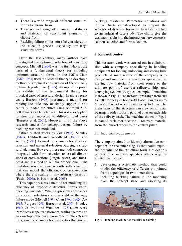
conveying systems. A typical example of machine
is shown in Fig. 1. The installations range from 300
to 6000 tonnes per hour with boom lengths up to
65 m and bucket wheel diameter up to 10 m. The
main mass of the structure can slew on an axial
bearing in order to form parallel piles on each side
of the railway track. The machine shown in Fig. 1
is named reclaimer because it recovers material
from the bucket wheel to the central pillar.
2.1 Industrial requirements
The company aimed to identify alternative con-
cepts for the reclaimer (Fig. 1) that could exploit
the potential of the structural form. Besides this
purpose, the industry specifies others require-
ments that include:
1. developing a systematic method that could
model the efficiency of different pin-jointed
frame topologies in two dimensions.
2. including buckling failure in the modeling
from the concept stage and assessing its
Fig. 1 Handling machine for material reclaiming
Int J Mech Mater Des
123
impact on the selection of structural form
concepts.
3. exploring how the structural efficiency
changes with the framework size, which is
specified by the max height and span of a
machine.
4. discriminating the efficiency benefits pro-
vided by the form of a structure from those
provided by its cross-sections.
5. providing design charts that show trends of
performance in addition to the optimum values.
2.2 Assumptions
For modeling structural efficiency at the concept
stage of design, the following simplifications were
arranged with the industry:
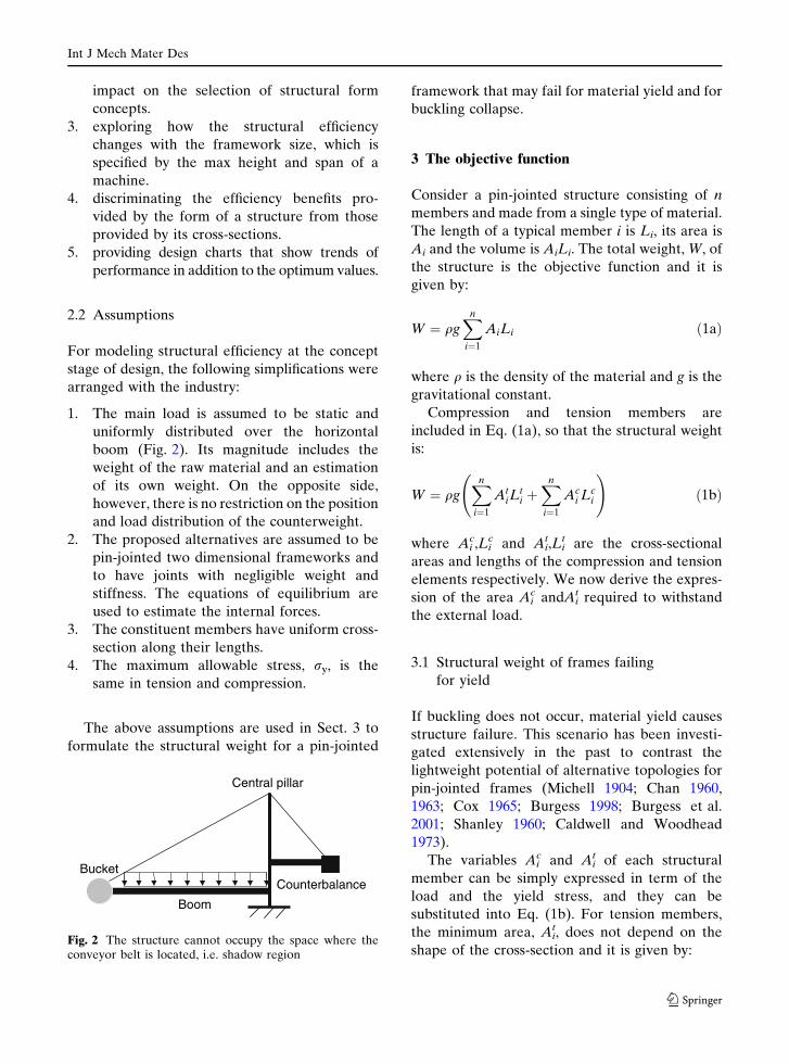
1. The main load is assumed to be static and
uniformly distributed over the horizontal
boom (Fig. 2). Its magnitude includes the
weight of the raw material and an estimation
of its own weight. On the opposite side,
however, there is no restriction on the position
and load distribution of the counterweight.
2. The proposed alternatives are assumed to be
pin-jointed two dimensional frameworks and
to have joints with negligible weight and
stiffness. The equations of equilibrium are
used to estimate the internal forces.
3. The constituent members have uniform cross-
section along their lengths.
4. The maximum allowable stress, ry, is the
same in tension and compression.
The above assumptions are used in Sect. 3 to
formulate the structural weight for a pin-jointed
framework that may fail for material yield and for
buckling collapse.
3 The objective function
Consider a pin-jointed structure consisting of n
members and made from a single type of material.
The length of a typical member i is Li, its area is
Ai and the volume is AiLi. The total weight, W, of
the structure is the objective function and it is
given by:
W ¼ qgXn
i¼1
AiLi ð1aÞ
where q is the density of the material and g is the
gravitational constant.
Compression and tension members are
included in Eq. (1a), so that the structural weight
is:
W ¼ qgXn
i¼1
AtiL
ti þXn
i¼1
Aci Lc
i
!ð1bÞ
where Aic,Li
c and Ait,Li
t are the cross-sectional
areas and lengths of the compression and tension
elements respectively. We now derive the expres-
sion of the area Aic andAi
t required to withstand
the external load.
3.1 Structural weight of frames failing
for yield
If buckling does not occur, material yield causes
structure failure. This scenario has been investi-
gated extensively in the past to contrast the
lightweight potential of alternative topologies for
pin-jointed frames (Michell 1904; Chan 1960,
1963; Cox 1965; Burgess 1998; Burgess et al.
2001; Shanley 1960; Caldwell and Woodhead
1973).
The variables Aic and Ai
t of each structural
member can be simply expressed in term of the
load and the yield stress, and they can be
substituted into Eq. (1b). For tension members,
the minimum area, Ait, does not depend on the
shape of the cross-section and it is given by:
Central pillar
BucketCounterbalance
Boom
Fig. 2 The structure cannot occupy the space where theconveyor belt is located, i.e. shadow region
Int J Mech Mater Des
123
Ati ¼
Fti
ryð2Þ
where Fit is the internal force in each tension
element caused by the load requirement.
Similarly, for compressive members where
buckling does not govern, the minimum area,
Aic, of an element does not depend on the shape
of the cross-section and it is given by:
Aci ¼
Fci
ryð3Þ
where Fic is the internal force in each compression
member caused by the load requirement.
Substituting Eqs. (2) and (3) in (1b) gives the
total weight of a framework as:
W ¼ qg
ry
Xn
i¼1
Fti L
ti þXn
i¼1
Fci Lc
i
!ð4Þ
Equation (4) confirms that the weight of a
structure varies with the number of members, n,
the forces magnitude, the member lengths as well
as the material properties. Because the geometry
of a cross-section is not a variable, only a change
of the structural form affects the objective func-
tion. Minimizing Eq. (4) provides the optima
number and member lengths that yield the
lightest topology.
In the past (Michell 1904; Chan 1960, 1963;
Cox 1965; Burgess 1998; Burgess et al. 2001), Eq.
(4) was used to explore the lightweight potential
of alternative theoretic pin-jointed frames. How-
ever, for practical structures, especially for large-
scale structures, Eq. (4) is of limited use, for
buckling is often a common failure mode that
cannot be neglected. The following section dis-
cusses such an issue and addresses a way to
include instability resistance in the model.
3.2 Structural weight for frames failing
for either buckling or yield
Large-scale structures can fail by mechanical
instability before the yield compressive stress is
reached. In this case, Eq. (3) does not describe the
minimum area for compressive member and
Equation (4) does not give the correct estimation
of the structural weight. The reason is that the
resistance to buckling is determined by the
efficiency of the cross-section and the element
length. Therefore, an expression of the cross-
section area is required to prevent buckling
failure. This section examines models for buckling
prediction and presents the approach that will be
used in this work.
The Euler formula is commonly used to model
buckling failure. It is quite appropriate for long
and slender struts with very small imperfections,
but it gives an inaccurate prediction for practical
cases. Real struts of any slenderness, indeed,
collapse at buckling loads less than the Euler
estimations. Improved models propose to adjust
the formula with a different value of the Young’s
Modulus. For example, Engesser (1889) suggests
replacing the Young’s modulus with the tangent
modulus,Et, while Karman (1956) proposes to use
the reduced modulus,Er. However, both the
models do not describe accurately instability.
The merit of presenting an exhaustive model
capable of describing the phenomenon is of
Shanley (1946). His theory of inelastic buckling
explains that buckling starts at Et and reaches Er
when the load increase causes large deformation.
Although Shanley’s theory gives an accurate
prediction of instability, its use can be problem-
atic when buckling is modeled at the concept
stage. The reason is that the estimation of both Et
and Er requires experimental data. The former
needs the strain-stress distribution to be evalu-
ated, and the latter involves also the modeling of
the convex and concave side of a strut.
Because the focus of this work is placed on the
concept design, a handier model is necessary. We
decide to opt for the Rankine and Gordon
formula. This approach is not as accurate as that
of Shanley, but it has the advantage that only
material and geometric properties are needed.
The formula is semi-empiric and it describes the
stress caused by either buckling or yield failure
for a strut of any length and with geometric
imperfections. His expression, rf, represents the
stability and strength constraint of a compressive
member, i, such that:
Int J Mech Mater Des
123
rf ¼Fc
i
Aci
¼ ry
1þ lLc
i
rgi
� �2ð5Þ
where l ¼ ry
p2Edepends on the material properties
and rgi, is the radius of gyration of the cross-
section.
From Eq. (5), the minimum area, Aic, required
to prevent both yield and buckling failure is:
Aci ¼
Fci ðr2
gi þ lLci
2Þryr2
gi
ð6Þ
The key parameter in Eq. (6) is the radius of
gyration. Once the designer specifies the cross-
section geometry of a member of given length and
material, rg can be evaluated to determine the
design variable, Aic, which represents the mini-
mum area required by each member to withstand
the internal force Fic.
It is noted that Aic is the minimum area of all
compressive loaded members of a frame. How-
ever, some elements are loaded more than
others and are more vulnerable to buckling. A
valuable alternative to this approach where the
cross-sectional area, i.e. expression (6), of each
members is minimized with respect to the
member stability constraint, i.e. expression (5),
involves two steps, as described in (Guo et al.
2005). The first is to impose a change of the
cross section area for only the heavily loaded
members. The second is to include in the
problem formulation the stability constraint of
the overall system.
We now recall that one key requirement of the
Industrial partner is to explore how the choice of
the member cross-sections impacts the selection
of a topology concept. If Eq. (6) were used in such
a form, then the designer would be forced to
decide at the onset all the geometric details of a
cross-section, and then calculate the value of rg.
As known, this task is left at later design stages
when the details of the geometry are defined. A
way to avoid such a decision is to provide
dimensionless parameters that describe the effi-
ciency of a cross-section and that may be substi-
tuted in Eq. (6). A method to do so is presented in
the following section.
4 Modelling the buckling resistance of different
cross-sections
To express the radius of gyration in term of
dimensionless parameters, we resort to Shape
Transformers and scaling factors (Pasini 2006a, b;
Pasini et al. 2003). This approach has been
introduced recently for comparing the relative
efficiency of cross-sections in bending and for
developing charts of material and shape selection.
It is well suited to optimize and select concepts at
the early stage of design.
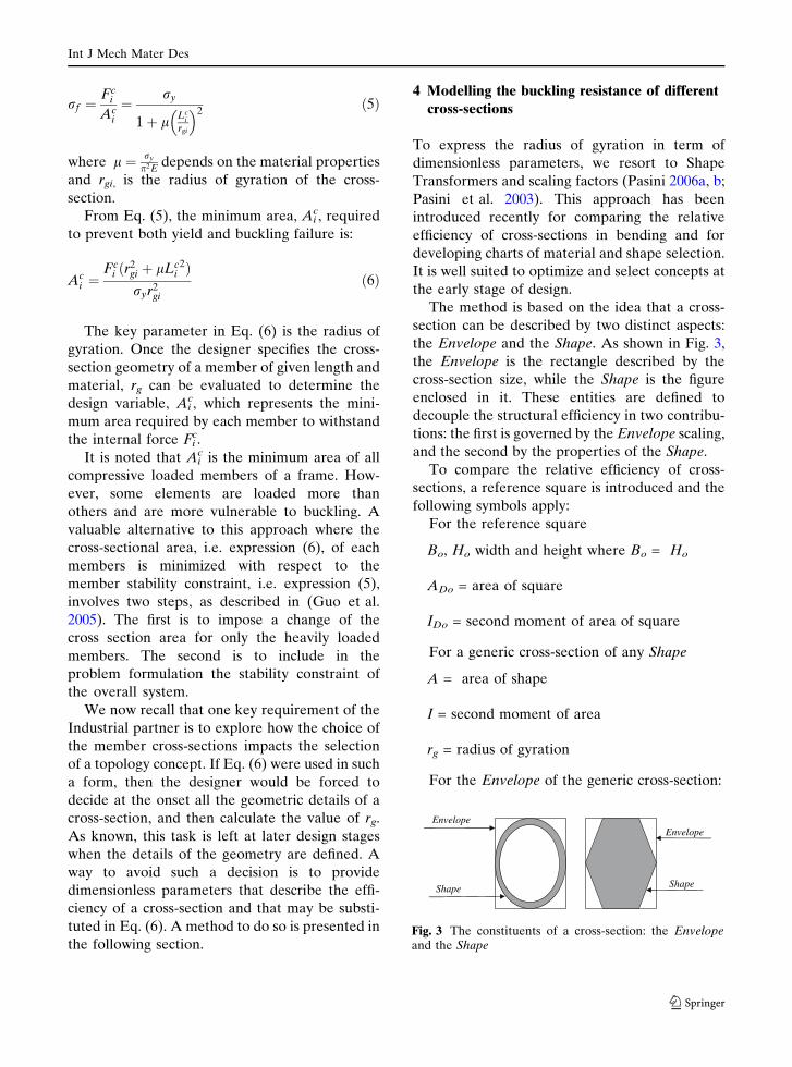
The method is based on the idea that a cross-
section can be described by two distinct aspects:
the Envelope and the Shape. As shown in Fig. 3,
the Envelope is the rectangle described by the
cross-section size, while the Shape is the figure
enclosed in it. These entities are defined to
decouple the structural efficiency in two contribu-
tions: the first is governed by the Envelope scaling,
and the second by the properties of the Shape.
To compare the relative efficiency of cross-
sections, a reference square is introduced and the
following symbols apply:
For the reference square
Bo, Ho width and height where Bo = Ho
ADo = area of square
IDo = second moment of area of square
For a generic cross-section of any Shape
A = area of shape
I = second moment of area
rg = radius of gyration
For the Envelope of the generic cross-section:
EnvelopeEnvelope
ShapeShape
Fig. 3 The constituents of a cross-section: the Envelopeand the Shape
Int J Mech Mater Des
123
B,H: width and height
AD = area of Envelope
ID = second moment of area of Envelope
rgD = radius of gyration
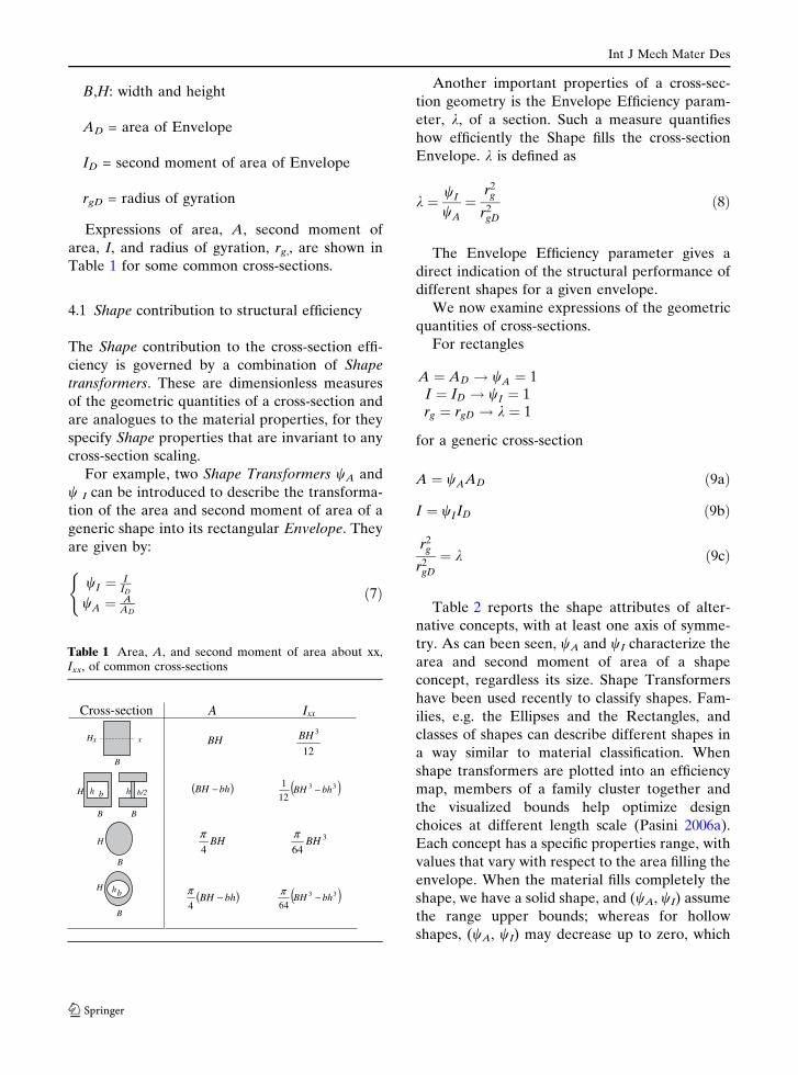
Expressions of area, A, second moment of
area, I, and radius of gyration, rg,, are shown in
Table 1 for some common cross-sections.
4.1 Shape contribution to structural efficiency
The Shape contribution to the cross-section effi-
ciency is governed by a combination of Shape
transformers. These are dimensionless measures
of the geometric quantities of a cross-section and
are analogues to the material properties, for they
specify Shape properties that are invariant to any
cross-section scaling.
For example, two Shape Transformers wA and
w I can be introduced to describe the transforma-
tion of the area and second moment of area of a
generic shape into its rectangular Envelope. They
are given by:
wI ¼ IID
wA ¼ AAD
(ð7Þ
Another important properties of a cross-sec-
tion geometry is the Envelope Efficiency param-
eter, k, of a section. Such a measure quantifies
how efficiently the Shape fills the cross-section
Envelope. k is defined as
k ¼ wI
wA
¼r2
g
r2gD
ð8Þ
The Envelope Efficiency parameter gives a
direct indication of the structural performance of
different shapes for a given envelope.
We now examine expressions of the geometric
quantities of cross-sections.
For rectangles
A ¼ AD ! wA ¼ 1I ¼ ID ! wI ¼ 1rg ¼ rgD ! k ¼ 1
for a generic cross-section
A ¼ wAAD ð9aÞ
I ¼ wIID ð9bÞ
r2g
r2gD
¼ k ð9cÞ
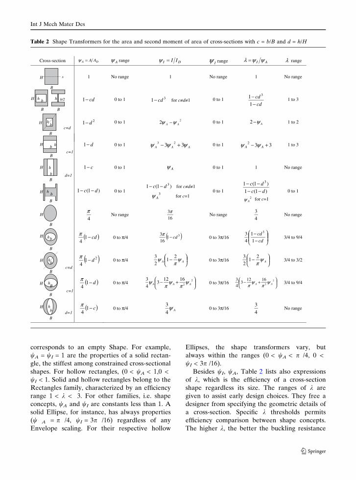
Table 2 reports the shape attributes of alter-
native concepts, with at least one axis of symme-
try. As can been seen, wA and wI characterize the
area and second moment of area of a shape
concept, regardless its size. Shape Transformers
have been used recently to classify shapes. Fam-
ilies, e.g. the Ellipses and the Rectangles, and
classes of shapes can describe different shapes in
a way similar to material classification. When
shape transformers are plotted into an efficiency
map, members of a family cluster together and
the visualized bounds help optimize design
choices at different length scale (Pasini 2006a).
Each concept has a specific properties range, with
values that vary with respect to the area filling the
envelope. When the material fills completely the
shape, we have a solid shape, and (wA, wI) assume
the range upper bounds; whereas for hollow
shapes, (wA, wI) may decrease up to zero, which
Table 1 Area, A, and second moment of area about xx,Ixx, of common cross-sections
Cross-section A Ixx
BH12
3BH
( )bhBH − ( )33
12
1bhBH −
BH4
π 3
64BH
π
( )bhBH −4
π ( )33
64bhBH −π
B
xH x
bh b/2h
BB
H
B
H
B
hbH
Int J Mech Mater Des
123
corresponds to an empty Shape. For example,
wA = wI = 1 are the properties of a solid rectan-
gle, the stiffest among constrained cross-sectional
shapes. For hollow rectangles, (0 < wA < 1,0 <
wI < 1. Solid and hollow rectangles belong to the
Rectangles family, characterized by an efficiency
range 1 < k < 3. For other families, i.e. shape
concepts, wA and wI are constants less than 1. A
solid Ellipse, for instance, has always properties
(w A = p /4, wI = 3p /16) regardless of any
Envelope scaling. For their respective hollow
Ellipses, the shape transformers vary, but
always within the ranges (0 < wA < p /4, 0 <
wI < 3p /16).
Besides wI, wA, Table 2 lists also expressions
of k, which is the efficiency of a cross-section
shape regardless its size. The ranges of k are
given to assist early design choices. They free a
designer from specifying the geometric details of
a cross-section. Specific k thresholds permits
efficiency comparison between shape concepts.
The higher k, the better the buckling resistance
Table 2 Shape Transformers for the area and second moment of area of cross-sections with c = b/B and d = h/H
Cross-section DA AA=ψ Aψ range DI II=ψIψ range AI ψψλ = λ range
1 No range 1 No range 1 No range
cd−1 0 to 1 31 cd− for c≠d≠1 0 to 1 cd
cd
−−
1
1 31 to 3
21 d− 0 to 1 22 AA ψψ − 0 to 1 Aψ−2 1 to 2
d−1 0 to 1 AAA ψψψ 33 23 +− 0 to 1 332 +− AA ψψ 1 to 3
c−1 0 to 1 Aψ 0 to 1 1 No range
)1( dc −− 0 to 1 )1(1 3dc −− for c≠d≠1
3Aψ for c=1
0 to 1 )1(1
)1(1 3
dc
dc
−−−−
2Aψ for c=1
0 to 1
4
πNo range
16
3πNo range
4
3No range
( )cd−14
π0 to π/4 ( )31
16
3cd−π
0 to 3π/16 ⎟⎟⎠
⎞⎜⎜⎝
⎛−
−cd
cd
1
1
4
3 3
3/4 to 9/4
( )214
d−π0 to π/4 ⎟
⎠⎞⎜
⎝⎛ − AA ψ
πψ 2
12
30 to 3π/16 ⎟
⎠⎞⎜
⎝⎛ − Aψ
π2
12
33/4 to 3/2
( )d−14
π0 to π/4 ⎟
⎠⎞⎜
⎝⎛ +− 2
2
16123
4
3AAA ψ
πψ
πψ 0 to 3π/16 ⎟
⎠⎞⎜
⎝⎛ +− 2
2
16123
4
3AA ψ
πψ
π 3/4 to 9/4
( )c−14
π0 to π/4 Aψ
4
30 to 3π/16
4
3No range
B
bh b/2h
BB
H
H x
hbH
c=dB
B
b hH
c=1
b
hH
d=1B
1H hb
B
H
B
B
hbH
B
hb
H
c=d
B
hB
H
c=1
B
hb
Hd=1
Int J Mech Mater Des
123
of the shape. These ranges, however, are theo-
retical because real cross-sections have reduced
ranges due to the difficult task of manufacturing
a material into a thin wall, shear failure require-
ments, and local instability. Shape transformers
have been recently used to develop design charts
that give insight into material and shape selec-
tion at different length scale (Pasini 2006a, b;
Pasini et al. 2003).
4.2 Envelope contribution to structural
efficiency
For a given type of shape such as a rectangular
section, it is well known that deep sections are
most efficient. This section describes a way of
modeling the efficiency of different envelopes for
a given shape. We specify a linear multiplicator, v,
for the relative arbitrary envelope scaling
between the height of the cross-section and the
square, as:
v ¼ H
Hoð10Þ
Thus the radius of gyration, rgD, of a generic
rectangle (wA = wI = k = 1) with respect to that,
rgDo, of the reference square is given by:
r2gD
r2gDo
¼ v2 ð11Þ
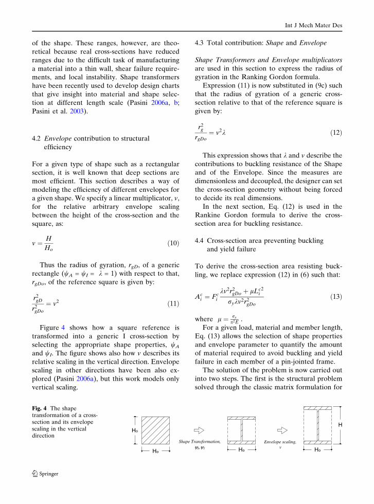
Figure 4 shows how a square reference is
transformed into a generic I cross-section by
selecting the appropriate shape properties, wA
and wI. The figure shows also how v describes its
relative scaling in the vertical direction. Envelope
scaling in other directions have been also ex-
plored (Pasini 2006a), but this work models only
vertical scaling.
4.3 Total contribution: Shape and Envelope
Shape Transformers and Envelope multiplicators
are used in this section to express the radius of
gyration in the Ranking Gordon formula.
Expression (11) is now substituted in (9c) such
that the radius of gyration of a generic cross-
section relative to that of the reference square is
given by:
r2g
rgDo¼ v2k ð12Þ
This expression shows that k and v describe the
contributions to buckling resistance of the Shape
and of the Envelope. Since the measures are
dimensionless and decoupled, the designer can set
the cross-section geometry without being forced
to decide its real dimensions.
In the next section, Eq. (12) is used in the
Rankine Gordon formula to derive the cross-
section area for buckling resistance.
4.4 Cross-section area preventing buckling
and yield failure
To derive the cross-section area resisting buck-
ling, we replace expression (12) in (6) such that:
Aci ¼ Fc
i
kv2r2gDo þ lLc
i2
rykv2r2gDo
ð13Þ
where l ¼ ry
p2E.
For a given load, material and member length,
Eq. (13) allows the selection of shape properties
and envelope parameter to quantify the amount
of material required to avoid buckling and yield
failure in each member of a pin-jointed frame.
The solution of the problem is now carried out
into two steps. The first is the structural problem
solved through the classic matrix formulation for
Envelope scaling,v
Shape Transformation,ψA,ψ I
H
Ho Ho
Ho
Ho
Fig. 4 The shapetransformation of a cross-section and its envelopescaling in the verticaldirection
Int J Mech Mater Des
123
a given pin-jointed framework. This requires the
use of equilibrium and compatibility conditions to
determine the unknown internal forces, Fic, as
function of the material properties and design
variables. The second one is the optimization
problem resolved by finding the cross-section area
variables that minimize the objective function.
This involves minimizing the frame weight given
by 1(b) with respect to the stability and strength
constraint, i.e. relation (13), of each frame mem-
ber. For a given concept, the result is an optimal
function, which is expressed in term of the cross-
section properties that enable the search of the
lightest structural form. The designer can there-
fore evaluate the impact that the selection of the
shape transformers has on the choice of an
optimum topology. This is shown in the next
section for three concepts of interest to the
collaborating company.
5 Industrial case study: the alternative structural
forms
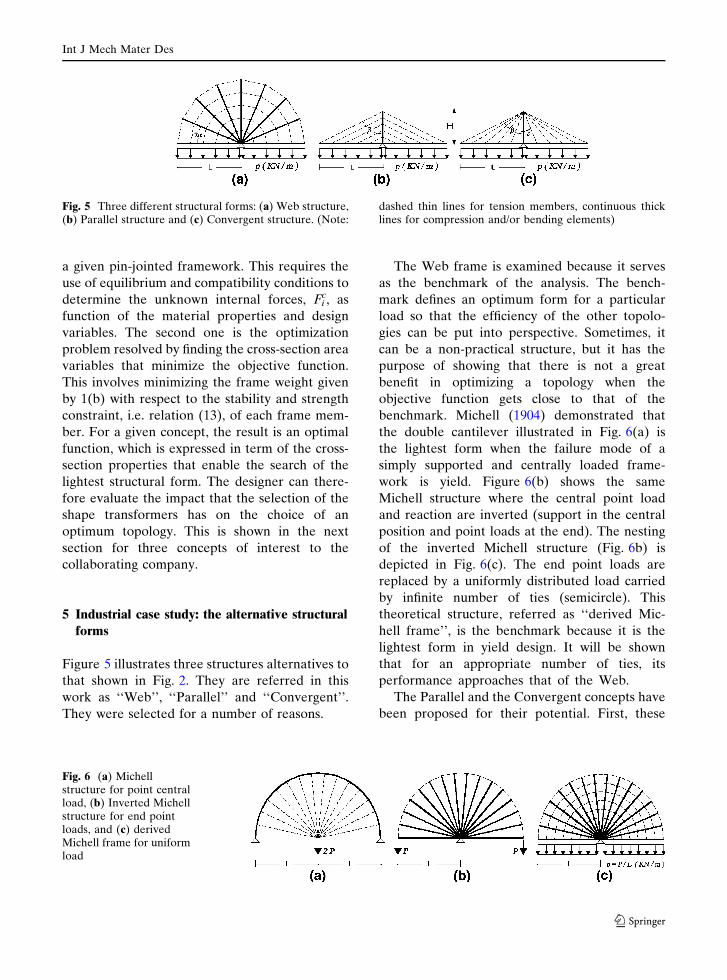
Figure 5 illustrates three structures alternatives to
that shown in Fig. 2. They are referred in this
work as ‘‘Web’’, ‘‘Parallel’’ and ‘‘Convergent’’.
They were selected for a number of reasons.
The Web frame is examined because it serves
as the benchmark of the analysis. The bench-
mark defines an optimum form for a particular
load so that the efficiency of the other topolo-
gies can be put into perspective. Sometimes, it
can be a non-practical structure, but it has the
purpose of showing that there is not a great
benefit in optimizing a topology when the
objective function gets close to that of the
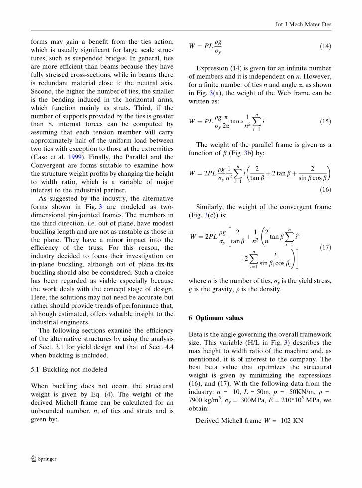
benchmark. Michell (1904) demonstrated that
the double cantilever illustrated in Fig. 6(a) is
the lightest form when the failure mode of a
simply supported and centrally loaded frame-
work is yield. Figure 6(b) shows the same
Michell structure where the central point load
and reaction are inverted (support in the central
position and point loads at the end). The nesting
of the inverted Michell structure (Fig. 6b) is
depicted in Fig. 6(c). The end point loads are
replaced by a uniformly distributed load carried
by infinite number of ties (semicircle). This
theoretical structure, referred as ‘‘derived Mic-
hell frame’’, is the benchmark because it is the
lightest form in yield design. It will be shown
that for an appropriate number of ties, its
performance approaches that of the Web.
The Parallel and the Convergent concepts have
been proposed for their potential. First, these
Fig. 5 Three different structural forms: (a) Web structure,(b) Parallel structure and (c) Convergent structure. (Note:
dashed thin lines for tension members, continuous thicklines for compression and/or bending elements)
Fig. 6 (a) Michellstructure for point centralload, (b) Inverted Michellstructure for end pointloads, and (c) derivedMichell frame for uniformload
Int J Mech Mater Des
123
forms may gain a benefit from the ties action,
which is usually significant for large scale struc-
tures, such as suspended bridges. In general, ties
are more efficient than beams because they have
fully stressed cross-sections, while in beams there
is redundant material close to the neutral axis.
Second, the higher the number of ties, the smaller
is the bending induced in the horizontal arms,
which function mainly as struts. Third, if the
number of supports provided by the ties is greater
than 8, internal forces can be computed by
assuming that each tension member will carry
approximately half of the uniform load between
two ties with exception to those at the extremities
(Case et al. 1999). Finally, the Parallel and the
Convergent are forms suitable to examine how
the structure weight profits by changing the height
to width ratio, which is a variable of major
interest to the industrial partner.
As suggested by the industry, the alternative
forms shown in Fig. 3 are modeled as two-
dimensional pin-jointed frames. The members in
the third direction, i.e. out of plane, have modest
buckling length and are not as unstable as those in
the plane. They have a minor impact into the
efficiency of the truss. For this reason, the
industry decided to focus their investigation on
in-plane buckling, although out of plane fix-fix
buckling should also be considered. Such a choice
has been regarded as viable especially because
the work deals with the concept stage of design.
Here, the solutions may not need be accurate but
rather should provide trends of performance that,
although estimated, offers valuable insight to the
industrial engineers.
The following sections examine the efficiency
of the alternative structures by using the analysis
of Sect. 3.1 for yield design and that of Sect. 4.4
when buckling is included.
5.1 Buckling not modeled
When buckling does not occur, the structural
weight is given by Eq. (4). The weight of the
derived Michell frame can be calculated for an
unbounded number, n, of ties and struts and is
given by:
W ¼ PLqg
ryð14Þ
Expression (14) is given for an infinite number
of members and it is independent on n. However,
for a finite number of ties n and angle a, as shown
in Fig. 3(a), the weight of the Web frame can be
written as:
W ¼ PLqg
ry
p2a
tan a1
n2
Xn
i¼1
i ð15Þ
The weight of the parallel frame is given as a
function of b (Fig. 3b) by:
W ¼ 2PLqg
ry
1
n2
Xn
i¼1
i2
tan bþ 2 tan bþ 2
sin b cos b
� �
ð16Þ
Similarly, the weight of the convergent frame
(Fig. 3(c)) is:
W ¼ 2PLqg
ry
2
tan bþ 1
n2
2
ntan b
Xn
i¼1
i2
"
þ2Xn
i¼1
i
sin bi cos bi
!# ð17Þ
where n is the number of ties, ry is the yield stress,
g is the gravity, q is the density.
6 Optimum values
Beta is the angle governing the overall framework
size. This variable (H/L in Fig. 3) describes the
max height to width ratio of the machine and, as
mentioned, it is of interest to the company. The
best beta value that optimizes the structural
weight is given by minimizing the expressions
(16), and (17). With the following data from the
industry: n = 10, L = 50m, p = 50KN/m, q =
7900 kg/m3, ry = 300MPa, E = 210*103 MPa, we
obtain:
Derived Michell frame W = 102 KN
Int J Mech Mater Des
123
Web: W = 112 KN
Convergent: Wmin = 160 KN for b = 58.18�
Parallel: Wmin = 142 KN for b = 45�
n = 10 is a sufficient number of ties to meet the
assumptions and to get the performance of the
Web closed to that of the derived Michell’s frame.
Therefore, the Web form is taken as the bench-
mark structure to compare to the Convergent and
the Parallel forms.
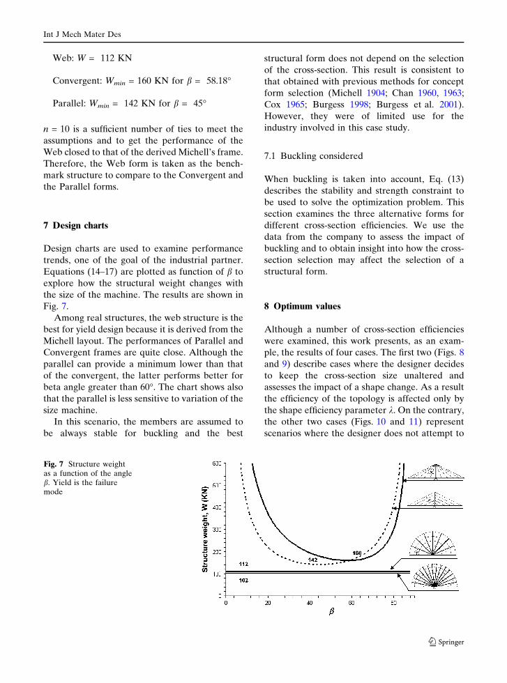
7 Design charts
Design charts are used to examine performance
trends, one of the goal of the industrial partner.
Equations (14–17) are plotted as function of b to
explore how the structural weight changes with
the size of the machine. The results are shown in
Fig. 7.
Among real structures, the web structure is the
best for yield design because it is derived from the
Michell layout. The performances of Parallel and
Convergent frames are quite close. Although the
parallel can provide a minimum lower than that
of the convergent, the latter performs better for
beta angle greater than 60�. The chart shows also
that the parallel is less sensitive to variation of the
size machine.
In this scenario, the members are assumed to
be always stable for buckling and the best
structural form does not depend on the selection
of the cross-section. This result is consistent to
that obtained with previous methods for concept
form selection (Michell 1904; Chan 1960, 1963;
Cox 1965; Burgess 1998; Burgess et al. 2001).
However, they were of limited use for the
industry involved in this case study.
7.1 Buckling considered
When buckling is taken into account, Eq. (13)
describes the stability and strength constraint to
be used to solve the optimization problem. This
section examines the three alternative forms for
different cross-section efficiencies. We use the
data from the company to assess the impact of
buckling and to obtain insight into how the cross-
section selection may affect the selection of a
structural form.
8 Optimum values
Although a number of cross-section efficiencies
were examined, this work presents, as an exam-
ple, the results of four cases. The first two (Figs. 8
and 9) describe cases where the designer decides
to keep the cross-section size unaltered and
assesses the impact of a shape change. As a result
the efficiency of the topology is affected only by
the shape efficiency parameter k. On the contrary,
the other two cases (Figs. 10 and 11) represent
scenarios where the designer does not attempt to
Fig. 7 Structure weightas a function of the angleb. Yield is the failuremode
Int J Mech Mater Des
123
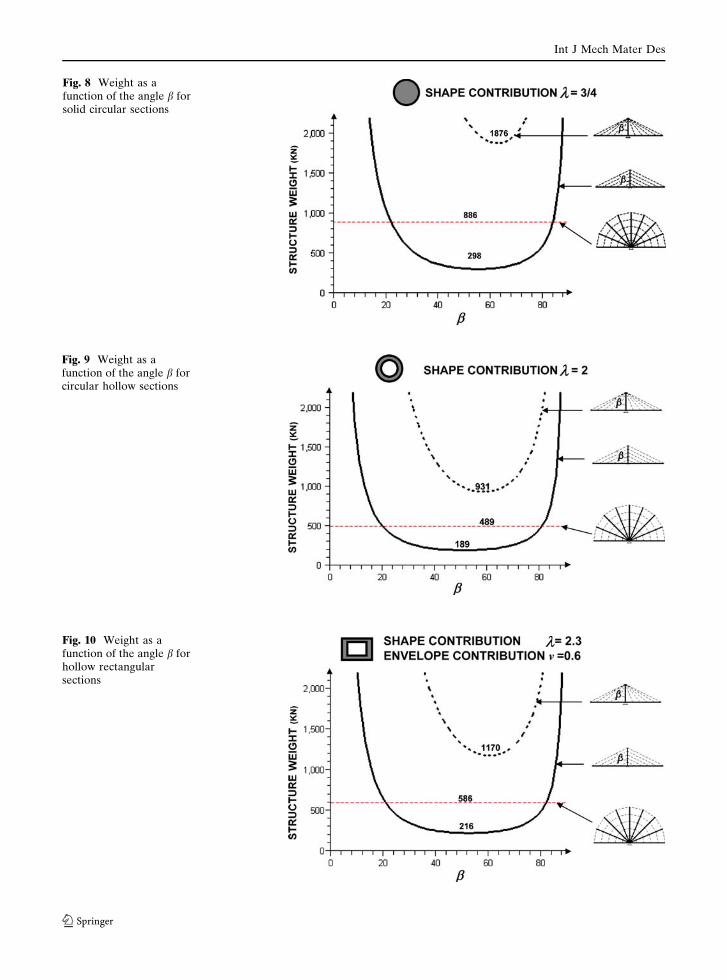
Fig. 10 Weight as afunction of the angle b forhollow rectangularsections
Fig. 9 Weight as afunction of the angle b forcircular hollow sections
Fig. 8 Weight as afunction of the angle b forsolid circular sections
Int J Mech Mater Des
123
minimize weight by optimizing the shape; rather
he chooses to scale the envelope. Hence the shape
efficiency contribution remains constant and the
envelope contribution is the only one governing
relative weight variation. The following report the
four cases.
1) We start with solid circular cross-sections
that have shape efficiency of k = 3/4 (see
Table 2). The minimum structural weight
and the optimum values of the variable bare:
Web: W = 886 KN
Convergent: Wmin = 1876 KN for b = 62.64�
Parallel: Wmin = 298 KN for b = 54.88�
2) Then we select a different shape, i.e. hollow
circular cross-section, that still belong to the
Ellipses family. From Table 2, the shape
efficiency contribution for this family should
be in the range 3/4 < k < 9/4. We chose k = 2
and we do not impose any scaling of the
envelope with respect to the previous case.
Thus, the minimum structural weight and the
optimum values of the variable b are given
by:
Web: W = 489 KN
Convergent: Wmin = 931 KN for b = 58.7�
Parallel: Wmin = 189 KN for b = 51.1�
3) In this scenario, we change shape properties
as well impose envelope scaling. An hollow
rectangular cross-section with shape effi-
ciency of k = 2.3 is chosen. The envelope
scaling is imposed to be v = 0.6. Here, the
minimum structural weight and the optimum
values of the variable b are:
Web: W = 586 KN
Convergent: Wmin = 1170 KN for b = 60.4�
Parallel: Wmin = 216 KN for b = 52.5�
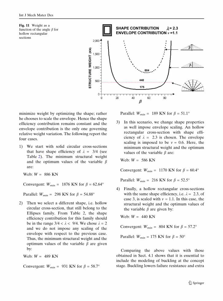
4) Finally, a hollow rectangular cross-sections
with the same shape efficiency, i.e. k = 2.3, of
case 3, is scaled with v = 1.1. In this case, the
structural weight and the optimum values of
the variable b are given by:
Web: W = 440 KN
Convergent: Wmin = 804 KN for b = 57.2�
Parallel: Wmin = 175 KN for b = 50�
Comparing the above values with those
obtained in Sect. 4.1 shows that it is essential to
include the modeling of buckling at the concept
stage. Buckling lowers failure resistance and extra
Fig. 11 Weight as afunction of the angle b forhollow rectangularsections
Int J Mech Mater Des
123
material is required to prevent failure. As
expected, the impact on the efficiency is sub-
stantial. The weight can double that obtained for
yield failure in the best scenario. But in the worse,
it can be up to 18 times.
9 Design charts
This section examines the weight trends for the
alternative structural forms resisting buckling.
The plots are shown in Figs. 8–11, and are given
in term of shape and envelope contributions for
the cross-section efficiencies considered in this
work. These are shown at the top of each chart. A
number of insight can be drawn by inspecting the
charts.
When the curves are compared to those
obtained for yield failure (Fig. 7), it can be seen
that the ranking of the structural form has
changed and there is a considerable effect on
the selection of the best form. The Web is not the
lightest structure concept because it has numer-
ous struts required to withstand buckling. This
feature impacts also the general performance
trends of the concepts. The curves in buckling
design are afar one from another and their
relative position is not as close as that obtained
for yield design.
The convergent frame performs always worse
because the central pillar has to support a
constant compressive force along the whole
length. This does not occur in the parallel frame
where the height decrease of each strut pair
lowers the vertical load. Furthermore, the parallel
is to be preferred because its performance is less
sensitive to variation of b. This feature is signif-
icant because gives the designer the freedom to
accommodate constraints that may limit the
design space.
Other insight can be drawn by inspection of
the charts in Figs. 8–11. Reductions in weight are
obtained by using the efficiency range shown in
Table 2 for different shape concepts. For exam-
ple, the plain comment that hollow sections
perform generally better than solid cross-sections
for a given envelope can be obtained when the
trends in Fig. 8 are contrasted to those in Fig. 9.
However, the benefit differs for each typology.
The convergent form makes the most of the
selection of hollow cross-section, because the
weight reduction is 50% of that obtained with
solid cross-section. The same shape change
applied to the Web and Parallel typologies,
however, yield to a lower performance benefits,
i.e. 45% and 37% respectively. On the other
hand, when hollow shapes are chosen to provide
the same efficiency, as the hollow rectangular
cross-sections illustrated in Figs. 10 and 11, the
designer can still obtain 20% of weight variation
by the sole envelope contribution. This confirms
that decoupling the shape contribution from that
of the envelope gives designers the freedom to
decide whether the lightest typology is obtained
by optimizing either the shape or the size or
both.
Besides the impact that the selection of the
cross-section has on the choice of a structural
form, the case study has shown also that the effect
of ties is beneficial for large scale structures.
However, only a proper selection of the Shape
and Envelope parameters can exploit the benefit
of a structural form.
10 Concluding remarks
Unlike previous methods of form selection for
the early stage of design, this paper has pre-
sented a method for modelling the mass-effi-
ciency of large-scale structures where buckling is
included as a failure mode. The method models
the geometric properties of arbitrary scaled
cross-sections and defines dimensionless effi-
ciency factors. These are included in parametric
equations that are used at the concept stage in
order to provide insight into the efficiency of a
structural concept. Design charts have shown
that the interaction between structural form and
cross-sections of compressive members affects
the selection of the best structure. The method
has been carried out on an industrial case study
in order to compare three different structural
forms for a particular design application. The
case study identified the potential of the three
structural forms and gave insight into the selec-
tion of the parameters that optimize structural
efficiency.
Int J Mech Mater Des
123
Acknowledgements The authors would like toacknowledge the support of Eng. Tony Burnett of MetsoMinerals Industries Inc., for his support and comments onthis work.
References
Ashby, M.F.: Materials and shape. Acta Metall. Mater.39(6), 1025–1039 (1991)
Burgess, S.C.: The ranking of efficiency of structural layoutsusing form factors. J. Eng. Sci. 212, 117–128 (1998)
Burgess, S.C., Pasini, D., Smith, D.J.: Form factors: A designmethod to support the selection of structural concepts.ICED 01, pp. 179–186, Glasgow, 21–23 (2001)
Caldwell, J.B., Woodhead, R.G.: Ship structures: somepossibilities for improvement. North East Cost Insti-tution – Inst. Eng. & Shipbuilders – Transaction, vol.89, pp. 101–120 (1973)
Case, J., Chilever, L., Ross, C.T.F.: Strength of materialsand structures. Arnold, London (1999)
Chan, A.S.L.: The Design of Michell Optimum Structures.The college of Aeronautics, Cranfield Report 142(1960)
Chan, H.S.Y.: Optimum Michell Frameworks for ThreeParallel forces. The College of Aeronautics, CranfieldReport 167 (1963)
Cox, H.L.: The Design of Structures of Least Weight.Pergamon Press, Oxford (1965)
Engesser, F.: Ueber die Knickfesrigkeit Gerader StTMbe.Zeitschrift for Architektur und Ingenieurwesen, vol.35, No. 4 Hannover, reported in Timoshenko, S.P.(1953). History of strength of materials. McGraw-Hill,New York (1889)
Guo, X., Cheng, G.D., Olhoff, N.: Optimum design of trusstopology under buckling constraints. Struct. Multidisc.Optim. 30(3), 169–180 (2005)
Karman, T.: Collected woks of Theodore von Karman.Butterworths Scientific Publications, London (1956)
Michell, A.G.M.: The limits of economy of material inframe-structures. Phil. Mag. 8, 589–597 (1904)
Pasini, D.: Shape transformers for material and shapeselection of lightweight beams. J. Mater. Design(2006a) in press
Pasini, D.: Material and shape selection for optimizingflexural vibrations in multilayered resonators. J. Mi-croelectromech. Syst. 15(6), 1745–1758 (2006b)
Pasini, D., Smith D.J., Burgess S.C.: (2003), Structuralefficiency maps for beams subjected to bending. P.Instn. Mech. Engrs. Part L: J. Mater. Design Appl.217(3), 207–220
Shanley, F.R.: The column paradox. J. Aeronaut. Sci.13(12) (1946)
Shanley, F.R.: Weight-strength Analysis of Aircraft Struc-tures, 2nd edn. Dover, New York (1960)
Int J Mech Mater Des
123