Embed Size (px)
Citation preview
ORNL/CP-94457
A METHOD FOR EFFICIENT FRACTIONAL SAMPLE DELAY GENERATION FOR REAL-TIME FREQUENCY-DOMAIN BEAMFORMERS
J. Eric Breeding Thomas P. Karnowski
Oak Ridge National Laboratory*
Paper to be presented at the International Conference on Signal Processing
Applications and Technology Boston, Mass.
October 24-26, 1995
-The suknmed mauaapt hss been authored by a contrkta of tho U S Government vda conbat No DE- AC05-840R21400 Aaxx&@y tho U S Goverrmwnt retam a mnexduwve rowb-har lrame to p&kh a reproducs the publrshed f a m of ths conmkmon. a anow O h r 6 to do 50 fa u s GoMmment PurPoses-
* Managed by Lockheed Martin Energy Systems, Inc. for the U.S. Department of Energy under contract DE-AC05-840R2 1400.
DISCLAIMER
This report was prepared as an account of work sponsored by an agency of the United States Government. Neither the United States Government nor any agency thereof, nor any of their employees, make any warranty, express or implied, or assumes any legal liabili- ty or responsibility for the accuracy, completeness, or usefulness of any information, appa- ratus, product, or process disclosed, or represents that its use would not infringe privately owned rights. Reference herein to any specific commercial product, pmess, or service by trade name, trademark, manufacturer, or otherwise does not necessarily constitute or imply its endorsement, recommendation, or favoring by the United States Government or any agency thereof. The views and opinions of authors expressed herein do not necessar- ily state or reflect those of the United States Government or any agency thereof.
A METHOD FOR EFFICIENT FRACTIONAL SAMPLE DELAY GENERATION FOR REAL-TIME FREQUENCY-DOMAIN BEAMFORMERS
J. Eric Breeding and Thomas P. Karnowski Oak Ridge National Laboratory*
P.O. Box 2008, Oak Ridge, Tennessee 3783 1-6007
Abstract
This paper presents an efficient method for fractional delay filter generation for fkequency-domain beamformers. A common misunderstanding regarding frequency- domain beamforming is that any fractional time shift can be achieved using the delay property of the discrete Fourier transform (DFT). Blind application of the DFT delay property introduces circular convolution errors that may adversely affect the beam’s time series. The method presented avoids these errors while enabling real-time processing.
I. Background
The beam pattern is the magnitude response of a spatial filter produced by summing the output signals from all sensors in an array. This filter response is characterized by a main lobe and several sidelobes. The main lobe is often referred to as the passband or maximum response axis (MRA) of the filter response [ 13. Beamforming may be defined as the process of changing the MRA of the array response using the weighted delay-and- sum beamformer equation given by [2]
M b(nT)=Cw,x,(nT-n,T) ,
i=I
where b(nT) is the time series beam, x, (nT) is the output signal of the i-th sensor, A4 is the number of sensors, Tis the temporal
sampling interval, and W, denotes the shading coefficient for the z-th sensor. Each time shift, ni, is selected on the basis of the desired MRA. Because the signals from the sensors are sampled, the achievable time shifts are limited to a set of quantized delays. Consequently, the number of achievable MRA steering directions is also limited.
The number of achievable steering directions is increased by increasing the sampling resolution [ 11. Because of the large amount of data produced by a sensor array, the most efficient method of increasing the sampling resolution is the generation of fractional samples. Interpolation beamforming is a technique that uses multirate digital signal processing to effectively increase the physical sampling frequency by a factor of L in order to increase the number of achievable steering directions [ 13. The interpolation beamformer equation is given by
b(nT) = M w, x, [ nT- (q +?)TI,
i= l
where m, is an integer from 0 to L - 1 and m,/L is the fractional delay required for the i- th sensor.
In the literature, the concept of fractional time shifts is traditionally approached from the time-domain beamforming perspective. Although the most intuitive approach, time- domain beamforming is not always the
* Managed by Lockheed Martin Energy Systems, Inc. for the U.S. Department of Energy under contract DE- AC0.5-840R2 1400.
preferred method. A technique that is becoming more feasible for real-time applications with the progress in high-speed computing is frequency-domain beamforming. Frequency-domain beamforming offers some computational advantages over the time-domain approach, particularly when an application calls for simultaneous production of multiple beams. Regardless of the implementation, the need for fractional sample generation exists. The purpose of Section I1 is to examine the interpolation beamformer from a frequency- domain perspective.
II. Fractional Delay Generation Using DFT Delay Property
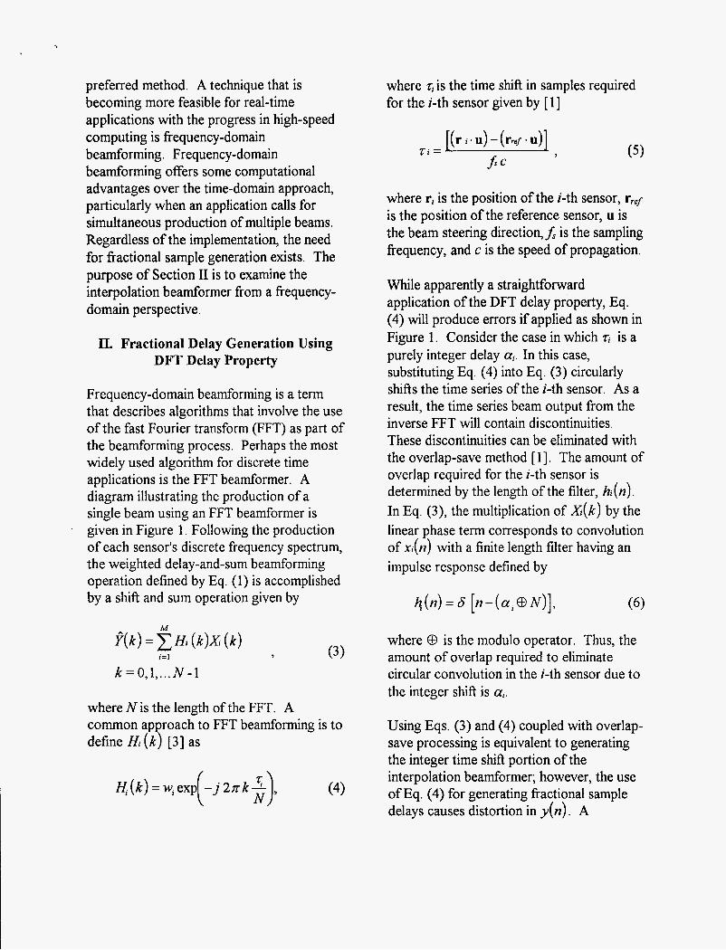
Frequency-domain beamforming is a term that describes algorithms that involve the use of the fast Fourier transform (FFT) as part of the beamforming process. Perhaps the most widely used algorithm for discrete time applications is the FFT beamformer. A diagram illustrating the production of a single beam using an FFT beamformer is given in Figure 1. Following the production of each sensor's discrete frequency spectrum, the weighted delay-and-sum beamforming operation defined by Eq. (1) is accomplished by a shift and sum operation given by
M
f( k) = 2 Hi (k)X (k) i=l >
k = 0,1,. .. N - I
where N is the length of the FFT. A common ap roach to FFT beamforming is to define Hi (k P [3] as
If(k)=w,exp -j27rk- , ( 3 (4)
where %is the time shift in samples required for the i-th sensor given by [ 11
where ri is the position of the z-th sensor, r,,f is the position of the reference sensor, u is the beam steering direction,f, is the sampling frequency, and c is the speed of propagation.
While apparently a straightforward application of the DFT delay property, Eq. (4) will produce errors if applied as shown in Figure 1. Consider the case in which q is a purely integer delay a,. In this case, substituting Eq. (4) into Eq. (3) circularly shifts the time series of the z-th sensor. As a result, the time series beam output from the inverse FFT will contain discontinuities. These discontinuities can be eliminated with the overlap-save method [ 11. The amount of overlap required for the i-th sensor is determined by the length of the filter, h ( n ) . In Eq. (3), the multiplication of X(k) by the linear phase term corresponds to convolution of xl(n) with a finite length filter having an impulse response defined by
where 0 is the modulo operator. Thus, the amount of overlap required to eliminate circular convolution in the i-th sensor due to the integer shift is a,.
Using Eqs. (3) and (4) coupled with overlap- save processing is equivalent to generating the integer time shift portion of the interpolation beamformer; however, the use of Eq. (4) for generating fractional sample delays causes distortion in y(n) . A
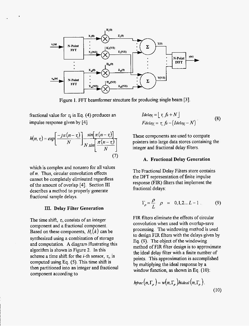
Figure 1. FFT beamformer structure for producing single beam [3].
fractional value for rj in Eq. (4) produces an impulse response given by [4]
N sin
(7)
which is complex and nonzero for all values of n. Thus, circular convolution effects cannot be completely eliminated regardless of the amount of overlap [4]. Section I11 describes a method to properly generate fractional sample delays.
III. Delay Filter Generation
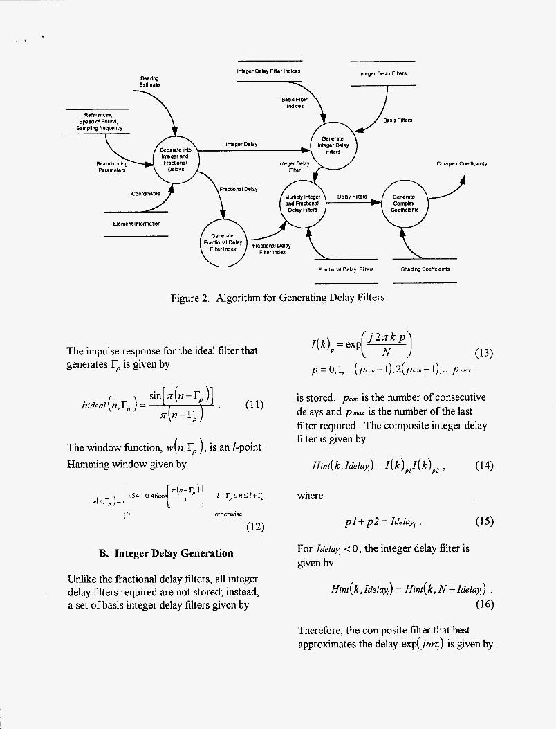
The time shift, .zi, consists of an integer component and a fractional com onent. Based on these components, H, P k ) can be synthesized using a combination of storage and computation. A diagram illustrating this algorithm is shown in Figure 2. In this scheme a time shift for the i-th sensor, Ti, is computed using Eq. (5). This time shift is then partitioned into an integer and fractional component according to
These components are used to compute pointers into large data stores containing the integer and fractional delay filters.
A. Fractional Delay Generation
The Fractional Delay Filters store contains the DFT representation of finite impulse response (FIR) filters that implement the fractional delays:
rp=- P p = O J , ~ ... L - 1 . L (9)
FIR filters eliminate the effects of circular convolution when used with overlap-save processing. The windowing method is used to design FIR filters with the delays given by Eq. (9). The object of the windowing method of FIR filter design is to approximate the ideal delay filter with a finite number of points. This approximation is accomplished by multiplying the ideal response by a window fbnction, as shown in Eq. (10):
.
Bearing Estimata
\
Integer Delay Fllter lndkes
Basis Filter indices
Integer Delay Fibers
-7-
Fractanal Delay Filters Shading Coeffckints
Figure 2. Algorithm for Generating Delay Filters.
The impulse response for the ideal filter that generates rp is given by
The window fbnction, w( n, rp ), is an I-point Hamming window given by
B. Integer Delay Generation
Unlike the fractional delay filters, all integer delay filters required are not stored; instead, a set of basis integer delay filters given by
p = 0, l,.. .(pm - 1),2(PO,- 1) ,... p m a r
is stored. PO, is the number of consecutive delays and p m a r is the number of the last filter required. The composite integer delay filter is given by
Hint( k , Idelq) = I ( k)pl I( k)pz ,
where
pl+ p 2 = Idelayi .
For Ideluyi < 0 , the integer delay filter is given by
(14)
Hint( k, Idelax) = Hint( k, N + Idehx) . (16)
Therefore, the composite filter that best approximates the delay exp(j0.r;) is given by
IV. Memory Requirements
The method presented in Section I11 provides significant improvement in required data storage. If every integer delay is stored, the amount of storage required for the integer and fractional delays is ( N + L)N complex words. This storage requirement would have exceeded the available 16 MB of memory in the array processor used for this application. Using the method in Section 111, all possible integer delays are obtained by a single complex vector multiplication. Splitting the integer delays in this manner results in a substantial memory storage savings. This technique requires Q sets of filter coefficients, where Q is given by
Solving for the minimum value of Q yields
Thus, the required storage space is reduced by a factor of F, where F is given by
For N >> L , the required storage space is reduced by approximately f i / 2 .
V. Summary
This paper presents a method for generating phase shifts for fkequency-domain
beamformers. The method utilizes the concept of fractional and integer delays to achieve the desired phase shift. The fractional delay component is produced by using FIR delay filters which are computed and stored prior to starting the beamformer. The use of FIR delay filters produces phase shifts without the circular convolution errors caused by blind application of the DFT delay property. The integer delays are produced efficiently by combining storage and computational resources. A base set of integer delays is generated and stored. From this set, all integer delays for a given FFT size are obtainable with a single complex vector multiplication. This compromise between memory storage and computation enables real-time frequency-domain beamforming operations.
VI. References
Neilson, Richard 0. Sonar Signal Processing. Boston: Artech House, 1991. Dudgeon, Dan E. and Russell M. Mersereau. Multidimensional Digital Signal Processing. Englewood Cliffs, NJ: Prentice Hall, 1984. Mucci, Ronald A. “A Comparison of Efficient Beamforming Algorithms”, IEEE Trans. Acoust., Speech, Signal Processing, Vol. ASSP- 32, (1984). Bomar, Bruce W. and L. Montgomery Smith. “Frequency-Domain Implementation of Fractional Sample Delays for Beamforming,” University of Tennessee Space Institute Report, 1991.
M98000325 I11111111 Ill lllll11111111111111111111111111111111111111
Report Number (14) f l il c P -- _. 9 LfLf57
Publ.
DOE


![Fractional Cascading Fractional Cascading I: A Data Structuring Technique Fractional Cascading II: Applications [Chazaelle & Guibas 1986] Dynamic Fractional](https://img.pdfslide.us/doc/110x75/56649ea25503460f94ba64dd/fractional-cascading-fractional-cascading-i-a-data-structuring-technique-fractional.jpg)