Embed Size (px)
Citation preview

A MEMS Based A MEMS Based Experimental Experimental
Colloid Thruster Package for Nano satellitesColloid Thruster Package for Nano satellites
Barry Kent, John Stark, Bob Stevens, Matt Alexander,Adam Baker, Dave Gibbon, Douglas Liddle
Space Science and Technology Department, Rutherford Appleton Laboratory,[email protected]
Department of Engineering, Queen Mary, University of London,[email protected]
Central Microstructures Facility, Rutherford Appleton Laboratory, [email protected]
Surrey Satellite Technology Ltd, University of Surrey,[email protected]
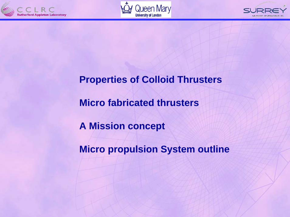
Properties of Colloid Thrusters
Micro fabricated thrusters
A Mission concept
Micro propulsion System outline

Comparison Parameters
Thrust
Specific Impulse
Delta V
=
=
M• Ve
Ve
g=TM• g
Mo Total spacecraft massg Acceleration due to gravityVe Exhaust velocityM Mass flow rateMf Mass of fuel
.
Thruster
= Ve Ln Mo
Mo - Mf
Mission Thruster S/C System

Basic Relationships for Electric Propulsion
qm
2 V½
Ve =Exhaust velocity
Mass Flow rate
Thrust
m Droplet massq droplet chargeV acceleration voltageM mass flow rateIb Beam current
.
M• = mq
Ib
T = M• qm
2 V½
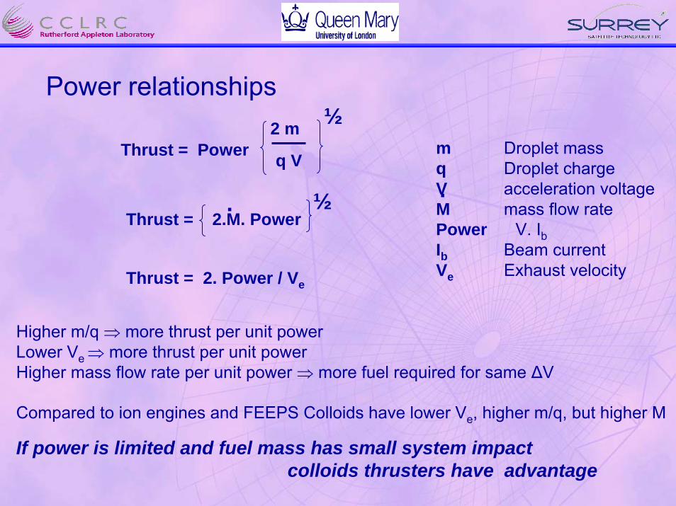
Power relationships
Thrust = Power2 m
q V
½m Droplet massq Droplet chargeV acceleration voltageM mass flow ratePower V. IbIb Beam currentVe Exhaust velocity
.Thrust = 2.M. Power
½.
Thrust = 2. Power / Ve
Higher m/q ⇒ more thrust per unit powerLower Ve ⇒ more thrust per unit powerHigher mass flow rate per unit power ⇒ more fuel required for same ∆V
Compared to ion engines and FEEPS Colloids have lower Ve, higher m/q, but higher M
If power is limited and fuel mass has small system impact colloids thrusters have advantage

Scaling Review (Electric Propulsion Thrusters with Isp > 300)
Type Gridded HET FEEP PPT MPD ArcJet Colloid
Thrust (mN) 1-50 1-70 µN -few 5 µN - mN 1N+ 1-few µN –few
Isp 2500 1000 5000 600 1000 300 3005000 1800 7000 1400 5000 600 1000
Rel System Mass High High Low High High Medium Low
Rel System Vol High High Low Medium Medium Medium Low
Rel Power High Medium Medium Low High High Low
Reference – Quinetiq Miniaturised EP Study

Summary of System Requirements for various missionsSummary of System Requirements for various missions
Science Small Satellite FormationFlying
(LISA Darwin) ( SSTL-DMC) (Proba 2.25)
Property
Thrust range (µN) 0.5 – 500 2,000 – 4,000 < 2000
Thrust Stability (µN) 0.1 - -
Specific Impulse (sec) ~ 500 >300 >500

Electrospray Components
Nano emitter
Taylor Cone
Fluid jet
Spray
560µm

Micro fabricated Colloid thruster concept
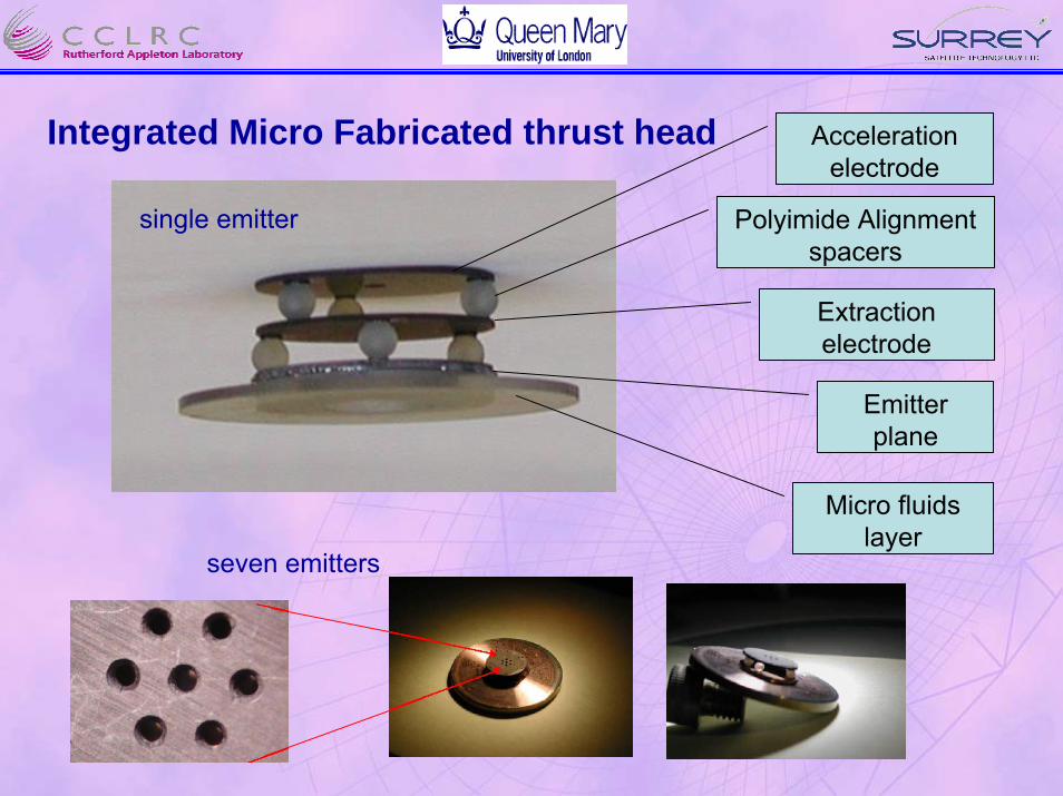
Acceleration electrode
Integrated Micro Fabricated thrust head
Extraction electrode
Polyimide Alignment spacers
single emitter
Emitter plane
Micro fluids layer
seven emitters
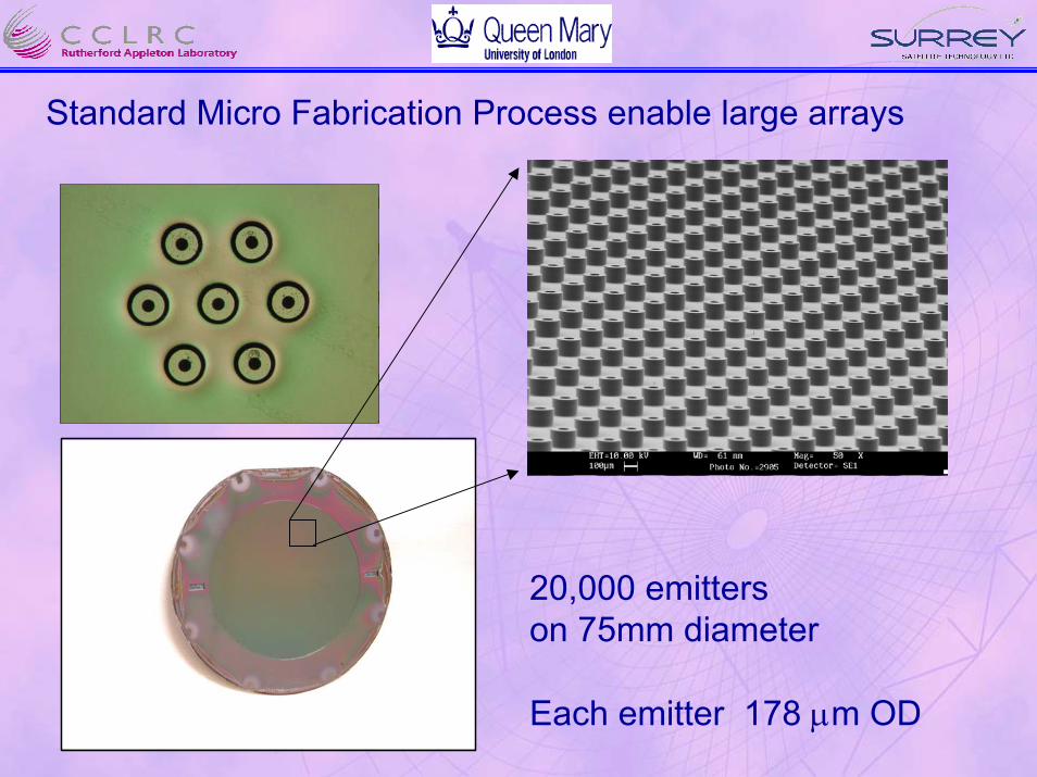
Standard Micro Fabrication Process enable large arrays
20,000 emitters on 75mm diameter
Each emitter 178 µm OD
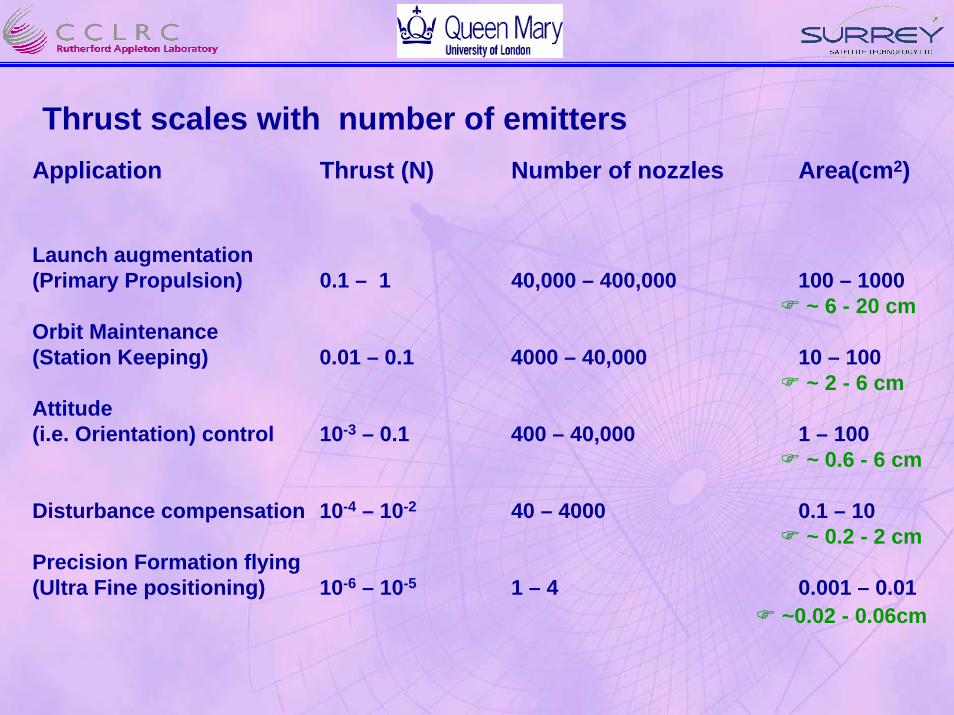
Thrust scales with number of emitters Application Thrust (N) Number of nozzles Area(cm2)
Launch augmentation(Primary Propulsion) 0.1 – 1 40,000 – 400,000 100 – 1000
~ 6 - 20 cmOrbit Maintenance(Station Keeping) 0.01 – 0.1 4000 – 40,000 10 – 100
~ 2 - 6 cmAttitude(i.e. Orientation) control 10-3 – 0.1 400 – 40,000 1 – 100
~ 0.6 - 6 cm
Disturbance compensation 10-4 – 10-2 40 – 4000 0.1 – 10~ 0.2 - 2 cm
Precision Formation flying(Ultra Fine positioning) 10-6 – 10-5 1 – 4 0.001 – 0.01
~0.02 - 0.06cm
Reference Mission
• Concept: formation flying/station-keeping using variable low thrust, with low thrust noise.
• Target mission is to track the motion of a nano satellite relative to a micro satellite
• Assumed baseline orbit is 700 km
• Launch near solar minimum conditions ~ 2006
• Micro satellite has mass 100kg, projected area 600mmx 800mmDrag at 700km (low solar activity) ~5x10⁻⁷ N
• Nano satellite has mass 10kg, projected area 465mmx 210mmDrag at 700km (low solar activity) ~9x10⁻⁸ N

• Mission analysis is based upon a linearized simulation
• Assumption that the major perturbation is due to atmospheric drag
• Require the orbit to remain near circular
• Adopt the approach of Cornelisse:
h = 2 x x - sin
h: change in height at altitude r0; T is thrust applied over time tVco local circular velocity; µ Earth’s gravitational parameter
• Neglect effects due to J2 etc
µro
2Tm
Vco tro
Vco tro
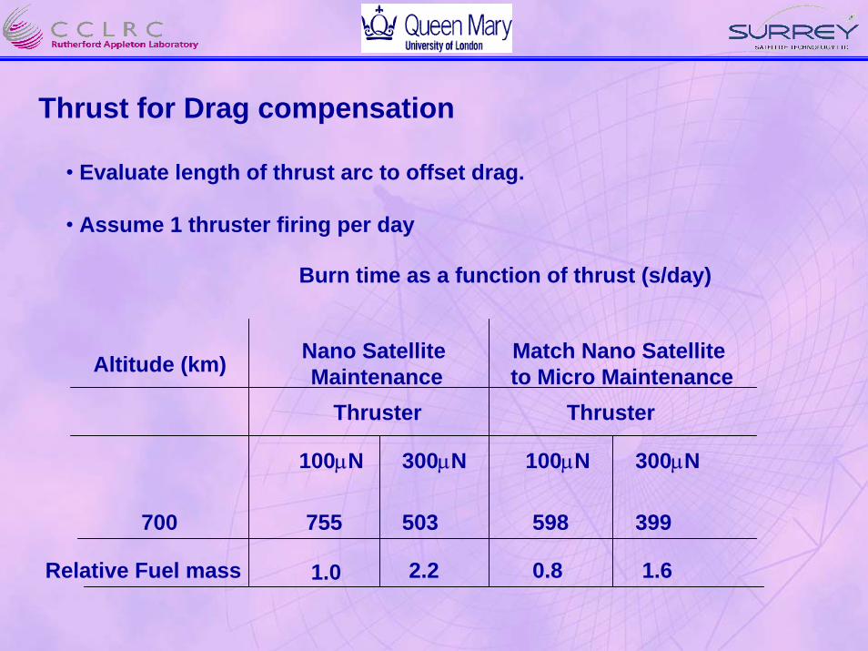
Thrust for Drag compensation
• Evaluate length of thrust arc to offset drag.
• Assume 1 thruster firing per day
Burn time as a function of thrust (s/day)
Nano SatelliteMaintenance
Match Nano Satelliteto Micro Maintenance
100µN 300µN 100µN 300µN
Altitude (km)
700 755 503 399598
Thruster Thruster
Relative Fuel mass 1.0 2.2 0.8 1.6
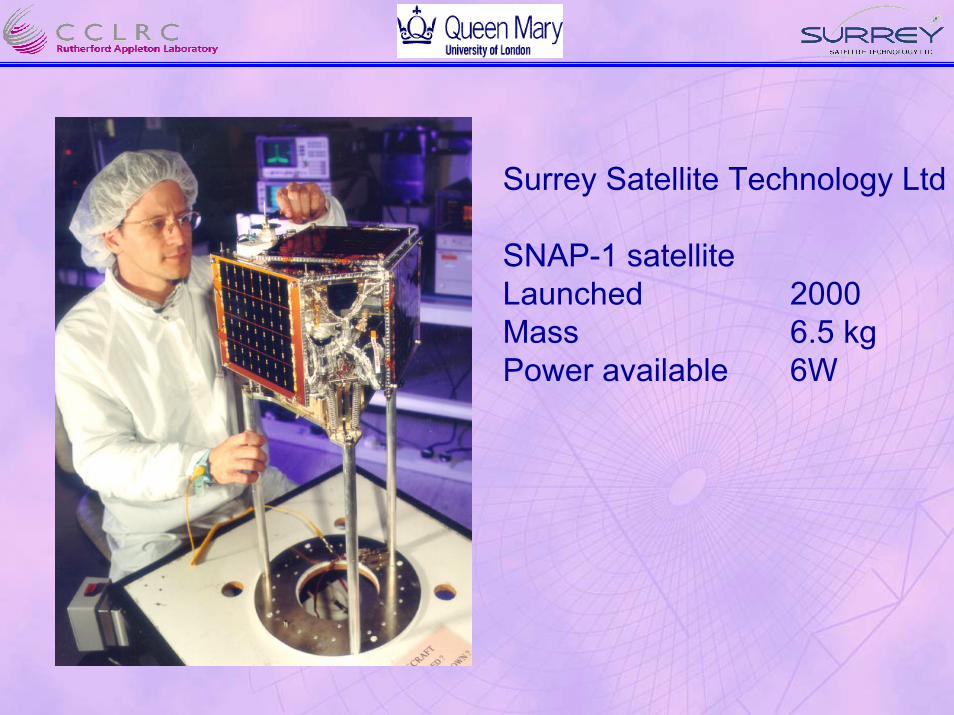
Surrey Satellite Technology Ltd
SNAP-1 satellite Launched 2000Mass 6.5 kgPower available 6W
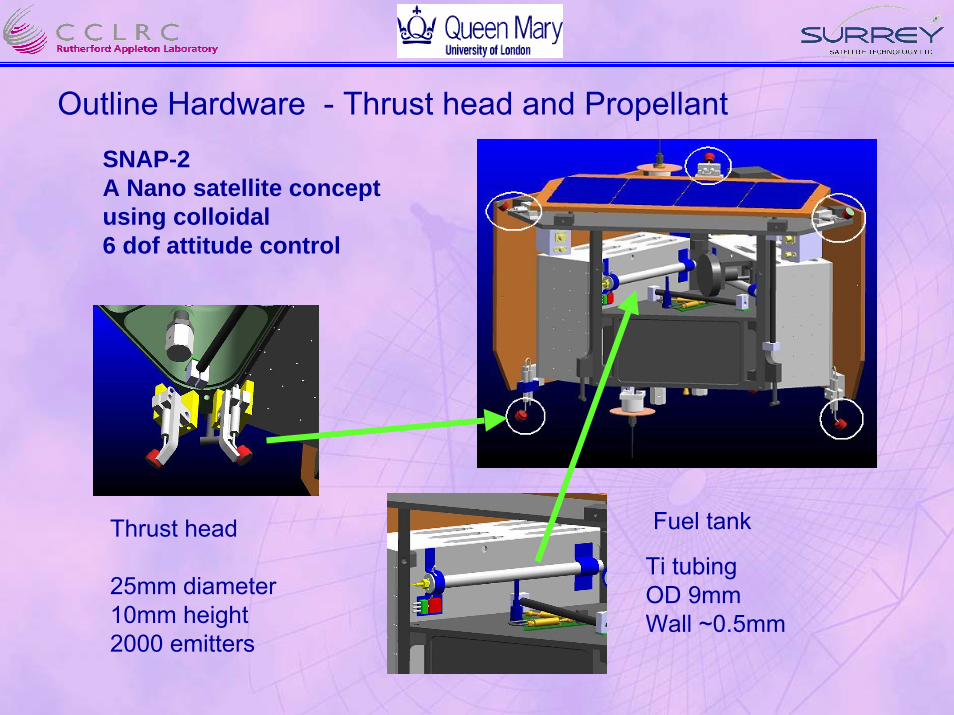
Outline Hardware - Thrust head and PropellantSNAP-2A Nano satellite concept using colloidal 6 dof attitude control
Fuel tankThrust head
25mm diameter10mm height2000 emitters
Ti tubing OD 9mmWall ~0.5mm

Outline Hardware - Propellant control valve
Example solenoid fluidcontrol valve
Lee Company
Power requirement ~ 0.75W

Outline Hardware - High Voltage supply
Cube
22 mm side
28g

S/C 0V
HT 1
HT 2
8kV
+200V
10kV +8 kV
+5V
(10kV isolated)5V PSU
Floats to 8kV+5V + Float
Optical link
Conducting fluid link
Thruster head
NeutraliserNeutraliser
psu
MonitorsT & P
Fuel Tank
S/C power S/C data bus
Interface circuitry 1
Valves
Interface circuitry 2
Propulsion System Connectivity
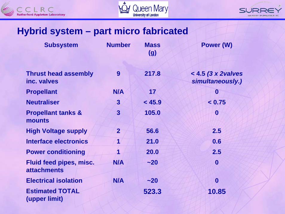
Hybrid system – part micro fabricatedSubsystem Number Mass
(g)Power (W)
Thrust head assembly inc. valves
9 217.8 < 4.5 (3 x 2valves simultaneously.)
Propellant N/A 17 0Neutraliser 3 < 45.9 < 0.75Propellant tanks & mounts
3 105.0 0
High Voltage supply 2 56.6 2.5Interface electronics 1 21.0 0.6Power conditioning 1 20.0 2.5Fluid feed pipes, misc. attachments
N/A ~20 0
Electrical isolation N/A ~20 0Estimated TOTAL (upper limit)
523.3 10.85
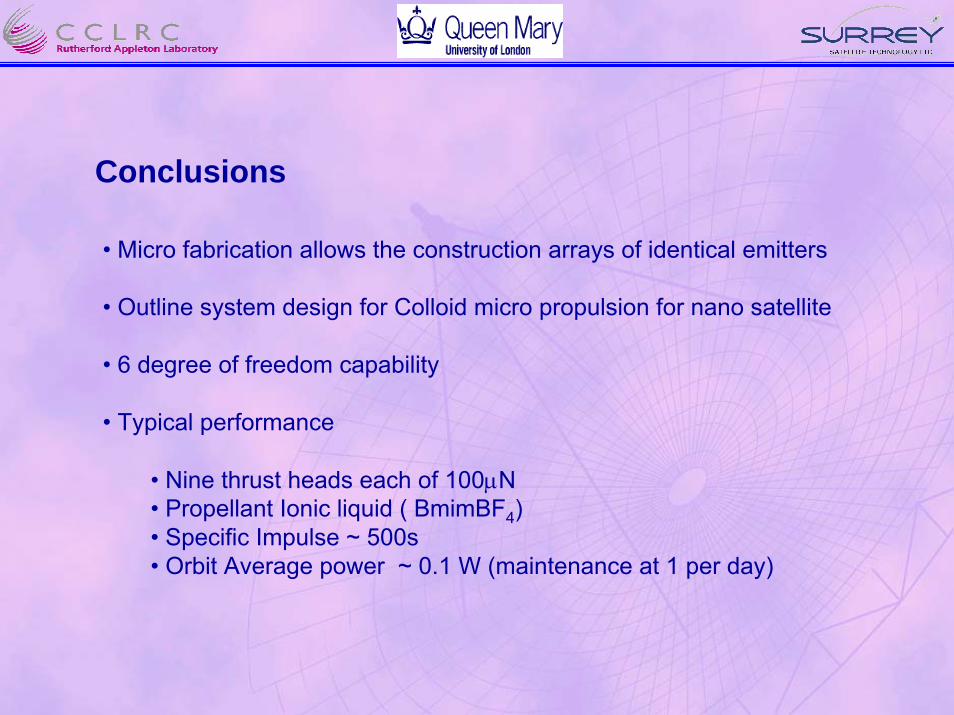
Conclusions
• Micro fabrication allows the construction arrays of identical emitters
• Outline system design for Colloid micro propulsion for nano satellite
• 6 degree of freedom capability
• Typical performance
• Nine thrust heads each of 100µN• Propellant Ionic liquid ( BmimBF4)• Specific Impulse ~ 500s• Orbit Average power ~ 0.1 W (maintenance at 1 per day)