Embed Size (px)
DESCRIPTION
PRESSURE SENSITIVE ADHESIVE
Citation preview
A MECHANISM-BASED APPROACH — VOID
GROWTH AND COALESCENCE IN POLYMERIC
ADHESIVE JOINTS
CHEW HUCK BENG
(M.Eng, B.Eng (Hons), NUS)
A THESIS SUBMITTED
FOR THE DEGREE OF DOCTOR OF PHILOSOPHY
DEPARTMENT OF MECHANICAL ENGINEERING
NATIONAL UNIVERSITY OF SINGAPORE
2007

ii
To my parents,
and my wife,
who truly are the wind beneath my wings.

iii
LIST OF PUBLICATIONS
Journal Papers
[1] Chew, H. B., Guo, T. F. and Cheng, L., Vapor pressure and residual stress effectson the toughness of polymeric adhesive joints. Engineering Fracture Mechanics,71 (2004), 2435-2448.
[2] Chew, H. B., Guo, T. F. and Cheng, L., Vapor pressure and residual stress effectson the failure of an adhesive film. International Journal of Solids and Structures,42 (2005), 4795-4810.
[3] Chew, H. B., Guo, T. F. and Cheng, L., Vapor pressure and residual stress effectson mixed mode toughness of an adhesive film. International Journal of Fracture,134 (2005), 349-368.
[4] Chew, H. B., Guo, T. F. and Cheng, L., Vapor pressure and voiding effects onthin film damage. Thin Solid Films, 504 (2006), 325-330.
[5] Chew, H. B., Guo, T. F. and Cheng, L., Effects of pressure-sensitivity and plasticdilatancy on void growth and interaction. International Journal of Solids andStructures, 43 (2006), 6380-6397.
[6] Chew, H. B., Guo, T. F. and Cheng, L., Pressure-sensitive ductile layers − I.Modeling the growth of extensive damage. International Journal of Solids andStructures, 44 (2007), 2553-2570.
[7] Chew, H. B., Guo, T. F. and Cheng, L., Pressure-sensitive ductile layers − II. 3Dmodels of extensive damage. International Journal of Solids and Structures, 44(2007), 5349-5368.
[8] Chew, H. B., Guo, T. F. and Cheng, L., Influence of non-uniform initial porositydistribution on adhesive failure in electronic packages. IEEE Transactions onComponents and Packaging Technologies, (2007), in Press.
Conference Papers
[1] Chew, H. B., Guo, T. F. and Cheng, L., Modeling interface delamination in plasticIC packages. Proceedings of APACK 2001 Conference on Advances in Packaging(ISBN 981-04-4638-1), 5-7 Dec 2001, Singapore, pp. 381- 388.
[2] Chew, H. B., Guo, T. F. and Cheng, L., A mechanism-based approach for inter-face toughness of ductile layer joining elastic solids. JSME/ASME Proceedings ofInternational Conference on Materials and Processing, 15-18 Oct 2002, Hawaii,Vol. 1, pp. 570-575.
[3] Chew, H. B., Guo, T. F. and Cheng, L., Computational study of vapor pressure andresidual stress effects on adhesive failure. Proceedings of International Conferenceon Scientific & Engineering Computation, 30 June - 02 July 2004, Singapore.

iv
[4] Chew, H. B., Guo, T. F. and Cheng, L., Computational study of compressivefailure of metallic foam. Proceedings of International Conference on Computa-tional Methods (ISBN-10 1-4020-3952-2), 15-17 Dec 2004, Singapore, Vol. 1, pp.563-568.
[5] Chew, H. B., Guo, T. F. and Cheng, L., Vapor pressure and voiding effects on thinfilm damage. Presented in International Conference on Materials for AdvancedTechnologies, 3-8 July 2005, Singapore.
[6] Chew, H. B., Guo, T. F. and Cheng, L., Influence of non-uniform initial porositydistribution on adhesive failure in electronic packages. Proceedings of 7th Elec-tronics Packaging Technology Conference (ISBN 0-7803-9578-6), 7-9 Dec 2005,Singapore, Vol. 2, pp. 6-11.
[7] Chew H. B., Guo, T. F. and Cheng, L., Void growth and damage ahead of a crackin pressure-sensitive dilatant polymers. Proceedings of International Conferenceon High Performance Structures and Materials (ISSN 1743-3509), 3-5 May 2006,Ostend, Belgium, Vol. 85, pp. 501-510.
[8] Chew, H. B., Guo, T. F. and Cheng, L., Modeling adhesive failure in electronicpackages. Proceedings of 8th Electronics Packaging Technology Conference (ISBN1-4244-0664-1), 6-8 Dec 2006, Singapore, Vol. 2, pp. 787-792.

v
ACKNOWLEDGEMENTS
I wish to acknowledge and thank those people who contributed to this thesis:
A/Prof. Cheng Li, thesis advisor, for her unwavering guidance and support
throughout the course of my studies at NUS. She never fails to pepper our conversations
with words of encouragement, or to slow down in her hectic schedule and provide a
listening ear whenever I needed one. The patience and care she demonstrated have not
only made my research journey fun and interesting, but most of all have enriched my
life with ever greater rewards.
Dr. Guo Tian Fu, research fellow and mentor, for his invaluable guidance and
insightful knowledge in continuum mechanics. His passion and enthusiasm for research
work was contagious and had been, and most surely will continue to be, a strong inspi-
ration to me.
Fellow postgraduates, Chong Chee Wei, and Tang Shan, for their friendships
and the moral support they had lent when I most needed it.
Directors and staff of EFE Engineering Pte Ltd, who were very supportive of my
undertaking throughout the first two years of my research journey on a part-time basis.
Eunice See, my other half, for having absolute confidence in me, and for giving me
the space and understanding I needed to work on my research at an excruciatingly slow
pace.
Finally, I am forever indebted to my parents and brother for their most precious
gift to me — love. I can never thank them enough for the love, understanding, patience
and encouragement that they had unselfishly given when I most needed them. Not
forgetting my furry companion Jo-Jo, who even after 12 wonderful years, never fails to
teach me the simplicity of love.

vi
TABLE OF CONTENTS
DEDICATION . . . . . . . . . . . . . . . . . . . . . . . . . . . . . . . . . . . . ii
LIST OF PUBLICATIONS . . . . . . . . . . . . . . . . . . . . . . . . . . . . iii
ACKNOWLEDGEMENTS . . . . . . . . . . . . . . . . . . . . . . . . . . . . v
LIST OF TABLES . . . . . . . . . . . . . . . . . . . . . . . . . . . . . . . . . x
LIST OF FIGURES . . . . . . . . . . . . . . . . . . . . . . . . . . . . . . . . xi
LIST OF SYMBOLS . . . . . . . . . . . . . . . . . . . . . . . . . . . . . . . . xvii
SUMMARY . . . . . . . . . . . . . . . . . . . . . . . . . . . . . . . . . . . . . . xix
1 INTRODUCTION . . . . . . . . . . . . . . . . . . . . . . . . . . . . . . . 1
2 BACKGROUND THEORY AND MODELING . . . . . . . . . . . . 6
2.1 Micromechanics of ductile fracture . . . . . . . . . . . . . . . . . . . . . 6
2.2 Mathematical models for void growth . . . . . . . . . . . . . . . . . . . 8
2.3 Mechanism-based models . . . . . . . . . . . . . . . . . . . . . . . . . . 8
2.3.1 Traction-separation relation . . . . . . . . . . . . . . . . . . . . 9
2.3.2 Cell element approach . . . . . . . . . . . . . . . . . . . . . . . 9
2.4 Pressure-dependent yielding . . . . . . . . . . . . . . . . . . . . . . . . 11
2.5 Crazing . . . . . . . . . . . . . . . . . . . . . . . . . . . . . . . . . . . . 14
2.5.1 Craze formation and growth . . . . . . . . . . . . . . . . . . . . 15
2.5.2 Micromechanical modeling . . . . . . . . . . . . . . . . . . . . . 17
2.5.3 Pressure-sensitivity effects . . . . . . . . . . . . . . . . . . . . . 18
3 MECHANISMS OF FAILURE FORADHESIVE LAYERWITHCEN-TERLINE CRACK . . . . . . . . . . . . . . . . . . . . . . . . . . . . . . 20
3.1 Introduction . . . . . . . . . . . . . . . . . . . . . . . . . . . . . . . . . 20
3.2 Modeling aspects . . . . . . . . . . . . . . . . . . . . . . . . . . . . . . 22
3.2.1 Adhesive properties . . . . . . . . . . . . . . . . . . . . . . . . . 22
3.2.2 Material model . . . . . . . . . . . . . . . . . . . . . . . . . . . 24
3.2.3 Boundary value problem . . . . . . . . . . . . . . . . . . . . . . 25
3.3 Uniform initial porosity distribution . . . . . . . . . . . . . . . . . . . . 27
3.3.1 Failures of low and high porosity adhesives . . . . . . . . . . . . 28
3.3.2 Temperature/moisture effects on failures of low porosity adhesives 31
3.3.3 Temperature/moisture effects on failures of high porosity adhesives 37

vii
3.4 Non-uniform initial porosity distribution . . . . . . . . . . . . . . . . . 37
3.4.1 Failures of low and high porosity adhesives . . . . . . . . . . . . 37
3.4.2 Vapor pressure induced adhesive failures . . . . . . . . . . . . . 39
3.5 Concluding remarks . . . . . . . . . . . . . . . . . . . . . . . . . . . . . 42
4 PARALLEL DELAMINATION ALONG INTERFACES OF DUC-TILE ADHESIVE JOINTS . . . . . . . . . . . . . . . . . . . . . . . . . 44
4.1 Introduction . . . . . . . . . . . . . . . . . . . . . . . . . . . . . . . . . 44
4.2 Problem formulation . . . . . . . . . . . . . . . . . . . . . . . . . . . . 45
4.3 Results and discussion . . . . . . . . . . . . . . . . . . . . . . . . . . . 47
4.3.1 Film-substrate CTE mismatch . . . . . . . . . . . . . . . . . . . 48
4.3.2 Residual stress in film . . . . . . . . . . . . . . . . . . . . . . . 50
4.3.3 Vapor pressure at film-substrate interface . . . . . . . . . . . . 52
4.3.4 Porosity of film-substrate interface . . . . . . . . . . . . . . . . 53
4.3.5 Strain hardening of film . . . . . . . . . . . . . . . . . . . . . . 53
4.3.6 Thickness of film . . . . . . . . . . . . . . . . . . . . . . . . . . 54
4.4 Concluding remarks . . . . . . . . . . . . . . . . . . . . . . . . . . . . . 57
5 INTERFACIAL TOUGHNESS OF DUCTILE ADHESIVE JOINTSUNDER MIXED MODE LOADING . . . . . . . . . . . . . . . . . . . 59
5.1 Introduction . . . . . . . . . . . . . . . . . . . . . . . . . . . . . . . . . 59
5.2 Modeling aspects . . . . . . . . . . . . . . . . . . . . . . . . . . . . . . 60
5.2.1 Material model . . . . . . . . . . . . . . . . . . . . . . . . . . . 60
5.2.2 Small-scale yielding . . . . . . . . . . . . . . . . . . . . . . . . . 62
5.3 Crack growth procedure and validation . . . . . . . . . . . . . . . . . . 65
5.3.1 Parametric dependence . . . . . . . . . . . . . . . . . . . . . . . 65
5.3.2 Model validation . . . . . . . . . . . . . . . . . . . . . . . . . . 65
5.4 Steady-state toughness . . . . . . . . . . . . . . . . . . . . . . . . . . . 68
5.4.1 Vapor pressure effects . . . . . . . . . . . . . . . . . . . . . . . . 68
5.4.2 Residual stress and vapor pressure effects . . . . . . . . . . . . . 70
5.4.3 Layer thickness effects . . . . . . . . . . . . . . . . . . . . . . . 73
5.5 Concluding remarks . . . . . . . . . . . . . . . . . . . . . . . . . . . . . 74
6 PRESSURE-SENSITIVITY AND PLASTIC DILATANCY EFFECTSON VOID GROWTH AND INTERACTION . . . . . . . . . . . . . . 76
6.1 Introduction . . . . . . . . . . . . . . . . . . . . . . . . . . . . . . . . . 76
6.2 Material model . . . . . . . . . . . . . . . . . . . . . . . . . . . . . . . 78

viii
6.3 Numerical modeling . . . . . . . . . . . . . . . . . . . . . . . . . . . . . 79
6.3.1 The axisymmetric cell . . . . . . . . . . . . . . . . . . . . . . . 79
6.3.2 Modeling aspects . . . . . . . . . . . . . . . . . . . . . . . . . . 80
6.4 Single void results . . . . . . . . . . . . . . . . . . . . . . . . . . . . . . 81
6.4.1 Initially spherical voids . . . . . . . . . . . . . . . . . . . . . . . 83
6.4.2 Initially ellipsoidal voids . . . . . . . . . . . . . . . . . . . . . . 85
6.4.3 Implications to IC package failure . . . . . . . . . . . . . . . . . 87
6.5 Multiple size-scale void interaction . . . . . . . . . . . . . . . . . . . . 92
6.6 Concluding remarks . . . . . . . . . . . . . . . . . . . . . . . . . . . . . 96
7 PRESSURE-SENSITIVE DUCTILE LAYERS: MODELINGTHEGROWTHOF EXTENSIVE DAMAGE . . . . . . . . . . . . . . . . . . . . . . . . 98
7.1 Introduction . . . . . . . . . . . . . . . . . . . . . . . . . . . . . . . . . 98
7.2 Problem modeling . . . . . . . . . . . . . . . . . . . . . . . . . . . . . . 99
7.2.1 Discrete void implementation . . . . . . . . . . . . . . . . . . . 100
7.2.2 Internal pressure . . . . . . . . . . . . . . . . . . . . . . . . . . 102
7.2.3 Model parameters . . . . . . . . . . . . . . . . . . . . . . . . . . 103
7.3 Unit-cell behavior . . . . . . . . . . . . . . . . . . . . . . . . . . . . . . 103
7.3.1 Equibiaxial straining . . . . . . . . . . . . . . . . . . . . . . . . 104
7.3.2 Uniaxial straining . . . . . . . . . . . . . . . . . . . . . . . . . . 105
7.4 Failure mechanisms in pressure-insensitive adhesives . . . . . . . . . . . 106
7.5 Damage evolution in pressure-sensitive adhesives . . . . . . . . . . . . . 108
7.5.1 Associated normality flow, β = α . . . . . . . . . . . . . . . . . 108
7.5.2 Non-associated flow, β < α . . . . . . . . . . . . . . . . . . . . . 111
7.5.3 Relative cell size . . . . . . . . . . . . . . . . . . . . . . . . . . . 113
7.6 Void coalescence and fracture toughness trend . . . . . . . . . . . . . . 115
7.7 Vapor pressure effects on adhesive damage . . . . . . . . . . . . . . . . 118
7.8 Concluding remarks . . . . . . . . . . . . . . . . . . . . . . . . . . . . . 120
8 PRESSURE-SENSITIVE DUCTILE LAYERS: 3DMODELS OF EX-TENSIVE DAMAGE . . . . . . . . . . . . . . . . . . . . . . . . . . . . . 122
8.1 Introduction . . . . . . . . . . . . . . . . . . . . . . . . . . . . . . . . . 122
8.2 Problem formulation . . . . . . . . . . . . . . . . . . . . . . . . . . . . 123
8.3 Model comparison . . . . . . . . . . . . . . . . . . . . . . . . . . . . . . 126
8.3.1 Three-dimensional versus two-dimensional discrete voids . . . . 127
8.3.2 Discrete voids versus computational cell elements . . . . . . . . 128

ix
8.4 Shape evolution and intervoid ligament reduction . . . . . . . . . . . . 130
8.4.1 Pressure-sensitivity effects . . . . . . . . . . . . . . . . . . . . . 130
8.4.2 Relative cell size effects . . . . . . . . . . . . . . . . . . . . . . . 133
8.5 Damage and fracture of pressure-sensitive adhesives . . . . . . . . . . . 136
8.5.1 Damage evolution ahead of crack . . . . . . . . . . . . . . . . . 136
8.5.2 Void coalescence and fracture toughness trends . . . . . . . . . 140
8.6 Softening-rehardening yield characteristics . . . . . . . . . . . . . . . . 143
8.7 Concluding remarks . . . . . . . . . . . . . . . . . . . . . . . . . . . . . 146
9 SUMMARY OF CONCLUSIONS . . . . . . . . . . . . . . . . . . . . . 149
9.1 Mechanisms of failure in adhesive joints . . . . . . . . . . . . . . . . . . 149
9.2 Interfacial toughness of adhesive joints . . . . . . . . . . . . . . . . . . 150
9.3 Pressure-sensitivity and plastic dilatancy effects . . . . . . . . . . . . . 151
9.4 Industrial implications . . . . . . . . . . . . . . . . . . . . . . . . . . . 153
9.5 Recommendations for future work . . . . . . . . . . . . . . . . . . . . . 153
REFERENCES . . . . . . . . . . . . . . . . . . . . . . . . . . . . . . . . . . . 156
APPENDIX A – THE CRACK DRIVING FORCE . . . . . . . . . . 165
APPENDIX B – RADIAL EQUILIBRIUM SOLUTION FOR AX-ISYMMETRIC VOID GROWTH . . . . . . . . . . . . . . . . . . . . . 167
APPENDIX C –VOIDGROWTHOFANAXISYMMETRIC PLANESTRAIN UNIT-CELL . . . . . . . . . . . . . . . . . . . . . . . . . . . . 169
APPENDIX D –STRAIN LOCALIZATION BEHAVIOROF AUNIT-CELL . . . . . . . . . . . . . . . . . . . . . . . . . . . . . . . . . . . . . . . 172

x
LIST OF TABLES
6.1 Peak axial stress for σ0/E = 0.002, ν = 0.3, N = 0.1 . . . . . . . . . . . 86
6.2 Critical mean stress for several void shapes under ψ = 0. σ0/E = 0.002, ν =0.3, N = 0.1, f0 = 0.005. . . . . . . . . . . . . . . . . . . . . . . . . . . 88
7.1 Critical mean stress and applied loads for cells ahead of the crack inpressure-sensitive adhesives with D = h/2, σ0/E = 0.01,N = 0.1. . . . . 112
7.2 Average critical porosity across cell distribution and cell sizes for severalpressure-dependent parameters. . . . . . . . . . . . . . . . . . . . . . . . 117

xi
LIST OF FIGURES
1.1 Typical fracture surface for rubber-modified adhesive (Imanaka et al., 2003). 4
2.1 Schematic of the Cell Element Approach. . . . . . . . . . . . . . . . . . 10
2.2 (a) Yield envelopes in the σ3 = 0 plane for PMMA at four temperatures(Quinson et al., 1997). (b) Effect of hydrostatic pressure on the compres-sive stress-strain curves of polycarbonate (Spitzig and Richmond, 1979). 12
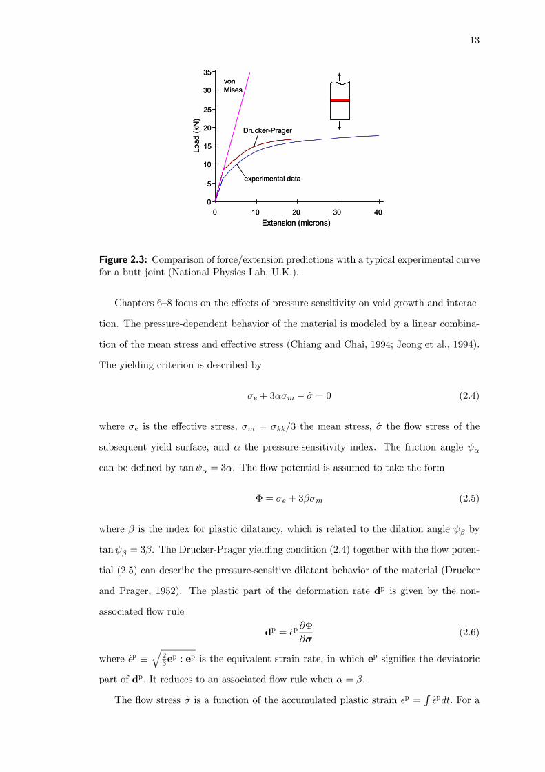
2.3 Comparison of force/extension predictions with a typical experimentalcurve for a butt joint (National Physics Lab, U.K.). . . . . . . . . . . . 13
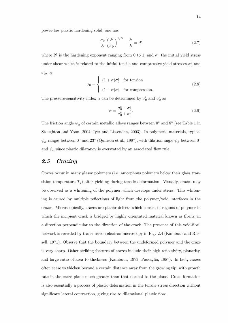
2.4 One-half of a craze in homopolystyrene, with centre of the craze at left-hand edge of top micrograph, and the right-hand craze tip at right sideof bottom micrograph (Kambour and Russell, 1971). . . . . . . . . . . . 15
2.5 Schematic illustration of the crazing mechanism (Krishnamachari, 1993). 16
2.6 Biaxial stress envelopes for craze initiation and yielding (Sternstein andOngchin, 1969). . . . . . . . . . . . . . . . . . . . . . . . . . . . . . . . . 17
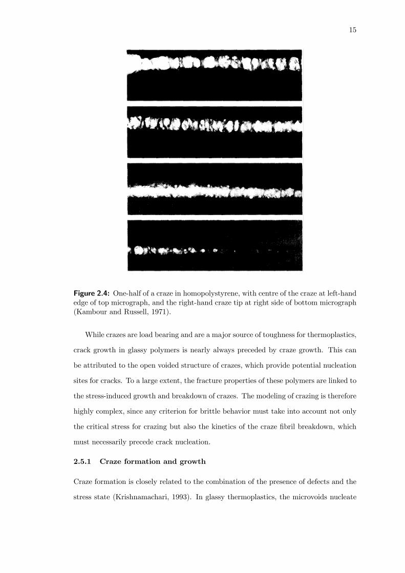
3.1 Three types of package cracks. (a) Type I; (b) Type II; (c) Type III. . . 21
3.2 Porosity distribution in a typical Ball Grid Array package (Trigg, 2003). 22
3.3 Typical solder reflow temperature profile. . . . . . . . . . . . . . . . . . 23
3.4 An adhesive (with a centerline crack) bonded to two elastic substratessubject to remote elastic KI field. . . . . . . . . . . . . . . . . . . . . . . 24
3.5 Finite element mesh for small scale yielding analysis. (a) Mesh of outerregion. (b) Refined mesh of inner region. (c) Near-tip mesh with severallayers of void-containing cell elements (D/2 byD/2). Cell is characterizedby f0 and p0. . . . . . . . . . . . . . . . . . . . . . . . . . . . . . . . . . 26
3.6 Porosity f and mean stress σm/σ0 ahead of crack (X2 = 0); f0 = 0.01,remote load only. . . . . . . . . . . . . . . . . . . . . . . . . . . . . . . . 29
3.7 Porosity f and mean stress σm/σ0 ahead of crack (X2 = 0); f0 = 0.05,remote load only. . . . . . . . . . . . . . . . . . . . . . . . . . . . . . . . 30
3.8 Porosity f ahead of crack (X2 = 0) and along adhesive/substrate interface(X2 = 0.5h) under four types of loading. f0 = 0.01, (i) remote load only;(ii) p0 = σ0, σR = 0; (iii) σR = σ0, p0 = 0; (iv) p0 = σR = σ0. . . . . . . 31
3.9 Contours of f = 0.05 for J/(σ0h) = 0.070 and J/(σ0h) = 0.088 under fourtypes of loading. f0 = 0.01, (i) remote load only; (ii) p0 = σ0, σR = 0;(iii) σR = σ0, p0 = 0; (iv) p0 = σR = σ0. . . . . . . . . . . . . . . . . . . 33
3.10 Mean stress under four types of loading for f0 = 0.01. (a) and (b) Stressahead of crack (X2 = 0); (i) remote load only; (ii) p0 = σ0, σR = 0; (iv)p0 = σR = σ0. (c) Stress along adhesive/substrate interface (X2 = 0.5h);(iii) σR = σ0, p0 = 0. . . . . . . . . . . . . . . . . . . . . . . . . . . . . . 34

xii
3.11 Porosity f ahead of crack (X2 = 0) under four types of loading. f0 = 0.05,(i) remote load only; (ii) p0 = σ0, σR = 0; (iii) σR = σ0, p0 = 0; (iv)p0 = σR = σ0. . . . . . . . . . . . . . . . . . . . . . . . . . . . . . . . . . 35
3.12 Mean stress ahead of crack (X2 = 0) under four types of loading. f0 =0.05, (i) remote load only; (ii) p0 = σ0, σR = 0; (iii) σR = σ0, p0 = 0; (iv)p0 = σR = σ0. . . . . . . . . . . . . . . . . . . . . . . . . . . . . . . . . . 36
3.13 Schematic of non-uniform initial porosity distribution in the adhesive film. 38
3.14 Contours of f = 0.05 for J/(σ0h) = 0.088 and J/(σ0h) = 0.094 withf0 = 0.01, p0 = σR = 0, (a) ∆f0/f0 = 0.0; (b) ∆f0/f0 = 0.3; (c)∆f0/f0 = 0.6. . . . . . . . . . . . . . . . . . . . . . . . . . . . . . . . . . 39
3.15 Contours of f = 0.1 for J/(σ0h) = 0.053 and J/(σ0h) = 0.070 withf0 = 0.05, p0 = σR = 0, (a) ∆f0/f0 = 0.0; (b) ∆f0/f0 = 0.3; (c)∆f0/f0 = 0.6. . . . . . . . . . . . . . . . . . . . . . . . . . . . . . . . . . 40
3.16 Contours of f = 0.05 for J/(σ0h) = 0.080 and J/(σ0h) = 0.094 withf0 = 0.01, p0 = σ0, σR = 0, (a) ∆f0/f0 = 0.0; (b) ∆f0/f0 = 0.6. . . . . . 41
3.17 Contours of f = 0.1 for J/(σ0h) = 0.050 and J/(σ0h) = 0.070 withf0 = 0.05, p0 = σ0, σR = 0, (a) ∆f0/f0 = 0.0; (b) ∆f0/f0 = 0.6. . . . . . 42
4.1 (a) Schematic of asymptotic crack problem involving parallel cracks alongfilm-substrate interfaces. (b) Finite element mesh showing close-up viewof crack-tip and void-containing cell elements. . . . . . . . . . . . . . . . 46
4.2 Crack growth induced by cool down process for three levels of CTE mis-match. (a) Temperature drop vs. crack growth along film-substrate in-terface of the joint; (b) crack growth resistance of the joint. . . . . . . . 49
4.3 Residual stress effect on crack growth along joint interface. (a) Crackgrowth resistance of the joint; (b) steady-state toughness of the joint; (c)plastic zone shape and size. . . . . . . . . . . . . . . . . . . . . . . . . . 51
4.4 Vapor pressure effect at film-substrate interface on crack growth resis-tance of the joint. (a) σR/σ0 = 0; (b) σR/σ0 = 1; (c) and (d) plasticzones corresponding to three cases considered in (a) and (b) respectively. 53
4.5 Effect of film-substrate porosity on crack growth resistance of the joint.(a) σR/σ0 = 1; p0/σ0 = 0; (b) σR/σ0 = 1; p0/σ0 = 1. . . . . . . . . . . . 54
4.6 Effect of hardening of film on crack growth resistance of the joint. (a)σR/σ0 = 1; p0/σ0 = 0; (b) σR/σ0 = 1; p0/σ0 = 1. . . . . . . . . . . . . . 55
4.7 Effect of thickness of film on crack growth resistance of the joint. (a)σR/σ0 = 0, p0/σ0 = 0; (b) σR/σ0 = 1, p0/σ0 = 0; (c) σR/σ0 = 1,p0/σ0 = 1. . . . . . . . . . . . . . . . . . . . . . . . . . . . . . . . . . . . 56
5.1 An adhesive (with an interface crack) joining two elastic substrates. . . 61
5.2 Finite element mesh for small-scale yielding analysis with h/D = 40. (a)Mesh of outer region. (b) Near-tip mesh with a strip of void-containingcell elements (D by D). The state of the cell is characterized by f0 and p0. 63
xiii
5.3 (a) Crack growth resistance plots for f0 = 0.05, N = 0.1, under ψ = 0◦,20◦ and 40◦. The solid curves are for p0 = 0 and the dotted curves forp0 = σ0. (b) Deformed mesh with scaling factor of 3 under ψ = 0◦, 20◦
and 40◦ for p0 = 0 at ∆a/D = 13.5 (crack advance by 14 elements). . . 66
5.4 Interface toughness versus mode mixity for three levels of elastic modulusmismatches with f0 = 0.05, N = 0.1. . . . . . . . . . . . . . . . . . . . . 68
5.5 Interface toughness versus mode mixity for three levels of vapor pressurewith (a) f0 = 0.05; (b) f0 = 0.01. The solid line curves are for N = 0.1and the dotted curves for N = 0.2. . . . . . . . . . . . . . . . . . . . . . 69
5.6 Interface toughness versus mode mixity for three levels of residual stresswith N = 0.1, (a) f0 = 0.05; (b) f0 = 0.01. The solid line curves are forp0 = 0 and the dotted curves for p0 = σ0. . . . . . . . . . . . . . . . . . 70
5.7 Interface toughness versus residual stress for three levels of vapor pressurefor ψ = 40◦, (a) f0 = 0.05; (b) f0 = 0.01. The solid line curves are forN = 0.1 and the dotted curves for N = 0.2. . . . . . . . . . . . . . . . . 72
5.8 Interface toughness versus mode mixity for three film thicknesses withf0 = 0.05, N = 0.1. The solid line curves are for p0 = 0 and the dottedcurves for p0 = σ0. . . . . . . . . . . . . . . . . . . . . . . . . . . . . . . 72
5.9 Interface toughness versus film thickness for f0 = 0.05, N = 0.1. The jointis subjected to four types of loading: remote load only; p0 = σ0, σR = 0;σR = σ0, p0 = 0; p0 = σR = σ0. (a) ψ = 0◦ (b) ψ = 20◦ (c) ψ = 40◦ (d)ψ = 60◦. . . . . . . . . . . . . . . . . . . . . . . . . . . . . . . . . . . . . 73
6.1 A unit cell in an axisymmetric state, with geometric parameters andsymmetry lines. . . . . . . . . . . . . . . . . . . . . . . . . . . . . . . . . 78
6.2 Finite element mesh for an initially (a) spherical void (b) oblate void(a/b = 3) with porosity f0 = 0.05 in a spherical matrix. . . . . . . . . . 82
6.3 Stress-strain curves of a cell volume containing a single void showinginfluence of plastic dilatancy β under ψ = 0. σ0/E = 0.01, ν = 0.4, N = 0for f0 = 0.01 with ψα = 0
◦, 15◦. . . . . . . . . . . . . . . . . . . . . . . . 83
6.4 (a) Stress-strain curves of a cell volume containing a single void show-ing influence of macroscopic strain triaxialities ψ = −0.3, 0, 1. σ0/E =0.01, ν = 0.4, N = 0 for f0 = 0.01 with ψα = 0
◦, 10◦, 20◦. (b) Void evolu-tion contours for f0 = 0.01 with ψα = 0
◦, 20◦ under ψ = 0. . . . . . . . . 84
6.5 Void shape effects for a cell volume containing a single void under uniaxialstraining (ψ = 0): (a) mean stress as a function of the evolution ofvoid volume fraction; (b) deviatoric stress against mean stress. σ0/E =0.01, ν = 0.4, N = 0 for f0 = 0.05, ψα = 0
◦, 10◦. . . . . . . . . . . . . . . 87
6.6 Critical mean stress plots showing (a) void shape effects with void vol-ume fraction under triaxial straining (ψ = 1); (b) void volume fractioninfluence with friction angle under uniaxial straining (ψ = 0). σ0/E =0.01, ν = 0.4, N = 0. . . . . . . . . . . . . . . . . . . . . . . . . . . . . . 89
6.7 Internal pressure effects for ψα = 0◦ and 20◦ on (a) spherical void growth
with various f0; (b) void growth with varying void shapes for f0 = 0.05.σ0/E = 0.01, ν = 0.4, N = 0. . . . . . . . . . . . . . . . . . . . . . . . . . 91

xiv
6.8 (a) Finite element mesh for a cell element containing a large void withf0 = 0.005, and a population of discrete microvoids; (b) close-up of themesh around one of the microvoids. . . . . . . . . . . . . . . . . . . . . . 92
6.9 Stress-strain curves of a cell volume with discrete microvoids for severalψα for (a) ψ = 0; (b) ψ = −0.7. σ0/E = 0.002, ν = 0.3, N = 0.1. . . . . 94
6.10 Stress-strain curves of a cell volume with discrete microvoids for severalψα for (a) ψ = 0; (b) ψ = −0.7. σ0/E = 0.01, ν = 0.4,N = 0.1. . . . . . 95
6.11 Contour maps of deformed void shapes for ψα = 0◦ and 15◦ at severalloading instants for (a) ψ = 0; (b) ψ = −0.7. σ0/E = 0.01, ν = 0.4, N = 0.1. 96
7.1 (a) An adhesive (with a centerline crack) bonded to two elastic substratessubject to remote elastic KI field. (b) Close-up view of the finite elementmesh near the crack-tip for f0 = 0.05, D = h/2. . . . . . . . . . . . . . . 101
7.2 Effects of pressure-sensitivity and plastic dilatancy for a unit-cell vol-ume containing a single void. (a) In-plane mean stress versus porosity ffor equibiaxial straining under associated flow. (b) Macroscopic stress-strain curves for uniaxial straining under non-associated flow. σ0/E =0.01, N = 0, f0 = 0.05. . . . . . . . . . . . . . . . . . . . . . . . . . . . 104
7.3 Distribution of porosity f ahead of crack (X2 = 0) for D = h/4; σ0/E =0.01, N = 0.1 (a) f0 = 0.005; (b) f0 = 0.05. . . . . . . . . . . . . . . . . 106
7.4 Distribution of porosity f ahead of crack (X2 = 0) for several pressure-sensitivity levels with α = β; D = h/2, σ0/E = 0.04, N = 0.1 (a)f0 = 0.005; (b) f0 = 0.05. . . . . . . . . . . . . . . . . . . . . . . . . . . 108
7.5 Distribution of porosity f ahead of crack (X2 = 0) for several pressure-sensitivity levels with α = β; D = h/2, σ0/E = 0.01, N = 0.1 (a)f0 = 0.005; (b) f0 = 0.05. . . . . . . . . . . . . . . . . . . . . . . . . . . 109
7.6 Distribution of porosity f ahead of crack (X2 = 0) for several pressure-sensitivity levels with α = β; D = h/2, σ0/E = 0.004, N = 0.1 (a)f0 = 0.002; (b) f0 = 0.005. . . . . . . . . . . . . . . . . . . . . . . . . . . 111
7.7 Distribution of porosity f ahead of crack (X2 = 0) for several plasticdilatancy levels with friction angles ψα = 10◦ and ψα = 20◦; σ0/E =0.04, N = 0.1 (a) f0 = 0.005; (b) f0 = 0.05. . . . . . . . . . . . . . . . . 113
7.8 Porosity f and mean stress Σm/σ0 evolution for unit-cells ahead of thecrack at X1/h = 2 for several cell sizes. f0 = 0.005, σ0/E = 0.01, N = 0.1.114
7.9 Crack growth resistance curves for (a) several cell sizes with f0 = 0.01 andf0 = 0.05; (b) f0 = 0.05 with ψα = ψβ = 0
◦ and 10◦. σ0/E = 0.01, N = 0.1.116
7.10 Distribution of (a) porosity f and (b) mean stress Σm/σ0 ahead of thecrack for f0 = 0.01 at J/(σ0h) = 0.06 with several internal pressures,p/σ0 = 0, 0.5 and 1. . . . . . . . . . . . . . . . . . . . . . . . . . . . . . 118
7.11 Distribution of (a) porosity f and (b) mean stress Σm/σ0 ahead of thecrack for f0 = 0.05 at J/(σ0h) = 0.03 with several internal pressures,p/σ0 = 0, 0.5 and 1. . . . . . . . . . . . . . . . . . . . . . . . . . . . . . 119

xv
8.1 (a) Schematic of periodic void distribution ahead of a crack. (b) Anadhesive with a centerline crack bonded to two elastic substrates subjectto remote elastic KI field. (c) Finite element mesh showing close-up viewof crack-tip and discrete voids with f0 = 0.01, D/h = 1/4. . . . . . . . . 124
8.2 Comparison of two- and three-dimensional discrete voids for porositydistribution f ahead of crack (X2 = 0) in pressure-insensitive layers(α = β = 0). σ0/E = 0.01, N = 0.1, D/h = 1/4, (a) f0 = 0.01; (b)f0 = 0.05. . . . . . . . . . . . . . . . . . . . . . . . . . . . . . . . . . . . 126
8.3 Comparison of three-dimensional discrete voids and computational cell el-ements for the porosity distribution f ahead of crack (X2 = 0) in pressure-insensitive layers (α = β = 0). σ0/E = 0.01, N = 0, D/h = 1/4, (a)f0 = 0.01; (b) f0 = 0.05. . . . . . . . . . . . . . . . . . . . . . . . . . . . 129
8.4 Comparison of three-dimensional discrete voids with two-dimensional dis-crete voids and computational cell elements for the porosity distributionf ahead of crack (X2 = 0) in pressure-insensitive layers (α = β = 0).σ0/E = 0.002, N = 0, D/h = 1/4, (a) f0 = 0.01; (b) f0 = 0.05. . . . . . 130
8.5 Porosity and mean stress evolution for unit-cells ahead of the crack atX1/h = 1 and 5 for several pressure-sensitivity levels under associatedflow, α = β. D/h = 1/2, σ0/E = 0.01, N = 0.1, f0 = 0.01. . . . . . . . . 131
8.6 Void shape history at X1/h = 1 and 5 and ligament reduction his-tory located to the right of the corresponding voids for several pressure-sensitivity levels under associated flow, α = β. D/h = 1/2, σ0/E =0.01, N = 0.1, f0 = 0.01. . . . . . . . . . . . . . . . . . . . . . . . . . . 132
8.7 Porosity and mean stress evolution for unit-cell ahead of the crack atX1/h = 1 for several relative cell sizes under associated flow, α = β.σ0/E = 0.01, N = 0.1, f0 = 0.01. . . . . . . . . . . . . . . . . . . . . . . 134
8.8 Void shape history at X1/h = 1 and ligament reduction history locatedto the right of the corresponding void for several relative cell sizes underassociated flow, α = β. σ0/E = 0.01, N = 0.1, f0 = 0.01. . . . . . . . . . 135
8.9 Distribution of porosity f ahead of crack (X2 = 0) for several pressure-sensitivity levels under associated flow, α = β. D/h = 1/2, σ0/E = 0.01,N = 0.1, (a) f0 = 0.01; (b) f0 = 0.05. . . . . . . . . . . . . . . . . . . . . 137
8.10 Variation of damage process zone length L with applied load J/(σ0h)for several pressure-sensitivity levels under associated and non-associatedflows. D/h = 1/2, σ0/E = 0.01, N = 0.1, f0 = 0.01, (a) 3D discretevoids; (b) 2D discrete voids. . . . . . . . . . . . . . . . . . . . . . . . . . 138
8.11 Deformed finite element meshes for pressure-sensitive layers under associ-ated flow, α = β, at J/(σ0h) = 0.12. D/h = 1/2, σ0/E = 0.01, N = 0.1,f0 = 0.01, (a) ψα = 0
◦; (b) ψα = 20◦. . . . . . . . . . . . . . . . . . . . . 139
8.12 (a) Effective stress-strain plots for a plane strain unit-cell subjected toΣ11/Σ22 = 0.5 under associated and non-associated flows. σ0/E = 0.01,N = 0.1, f0 = 0.01. (b) Variation of JIC/(σ0h) with friction angleψα for pressure-sensitive layers under associated flow, α = β. D/h =1/2, σ0/E = 0.01, N = 0.1, f0 = 0.05. . . . . . . . . . . . . . . . . . . . 142
xvi
8.13 Uniaxial true stress-strain response for the unvoided material: softening-rehardening description where rate of rehardening is controlled by theparametric setting of ξ = 1 and η = 10, 20, 40, 100 for σ0/E = 0.01,ν = 0.4. . . . . . . . . . . . . . . . . . . . . . . . . . . . . . . . . . . . . 144
8.14 Distribution of porosity f ahead of crack (X2 = 0) for several η. D = h/2,σ0/E = 0.01, (a) f0 = 0.01; (b) f0 = 0.05. . . . . . . . . . . . . . . . . . 145
8.15 Deformed finite element meshes for polymeric layers with f0 = 0.01, D =h/2 at J/(σ0h) = 0.12. (a) η = 20, ψα = 0◦; (b) η = 20, ψα = 10◦; (c)η = 100, ψα = 0
◦; (d) η = 100, ψα = 10◦. . . . . . . . . . . . . . . . . . 148
D.1 Plastic strain contours for η = 20 and 100 under low stress triaxialityT = 2/3 for elastic-plastic material, i.e. α = β = 0. . . . . . . . . . . . . 173
D.2 Plastic strain contours for η = 20 and 100 under high stress triaxialityT = 2 for elastic-plastic material, i.e. α = β = 0. . . . . . . . . . . . . . 174
D.3 Plastic strain contours for η = 20 under stress triaxiality T = 1 at Ee =0.031 for several pressure-sensitivity levels: ψα = 0
◦, 10◦, 20◦. . . . . . . 174

xvii
LIST OF SYMBOLS
α pressure-sensitivity index, Eq. (2.4)
α coefficient of thermal expansion
β plastic-dilatancy index, Eq. (2.5)
∆a crack propagation distance
∆f0 amplitude of initial porosity non-uniformity
0 reference yield strain
p accumulated plastic strain
ξ index controlling the intrinsic yield point
Γ fracture resistance
Γss steady-state fracture toughness
ν, νs Poisson’s ratio of film/substrate
η index controlling the softening-rehardening shape of the stress-strain curve
μ, μs shear moduli for film/substrate
Φ flow potential
σ flow stress of the matrix
σe,Σe equivalent stress
σm,Σm mean stress
Σcm critical mean stress
σ0 reference yield stress
σR initial residual stress
ψ mode mixity level (chapter 5); strain proportion (chapter 6)
ψα friction angle
ψβ dilation angle
D cell size
E,Es Young’s modulus of film/substrate
G applied energy release rate
Gtip near-tip energy release rate

xviii
J J-integral
K applied remote load
KI ,KII mode I/II stress-intensity factor
Ktip near-tip complex stress intensity factor
N power-law hardening exponent
T current temperature (chapters 3—5); stress triaxiality (chapters 6—8)
T0 reference temperature
Tg glass transition temperature
f0, f initial/current void volume fraction
f0 mean initial porosity
f∗ accelerated value of the current void volume fraction
fC critical void volume fraction for coalescence
fE porosity to trigger cell extinction
fF void volume fraction at final rupture
ftip porosity denoting crack-tip location
h film thickness
p0, p initial/current internal vapor pressure
pc critical pressure
q1, q2 Gurson model calibration parameters

xix
SUMMARY
Polymeric adhesive joints are some of the most critical features in composites,
including multi-layered devices and plastic electronic packages. Such joints can fail by
ductile rupture arising from the high stress triaxiality within the layer, or by interface
de-adhesion which occurs when the bond strength is weak. These failure behaviors are
exacerbated by the presence of numerous pores and cavities within the adhesive film
as well as along the interfaces. Furthermore, the synergistic action of thermal stress
and vapor pressure under severe environmental conditions could trigger unstable void
growth and coalescence, which makes the joint more susceptible to delamination and
failure. These damaging effects of temperature and moisture on adhesive failure have
not received due attention in the literature.
In this thesis, detailed numerical studies are performed to examine the mechanics
and mechanisms of failure in polymeric adhesive joints. Part I involves the develop-
ment of a mechanism-based failure model to study the role of residual stress and vapor
pressure on void growth and rupture in constrained adhesive films. Damage in the adhe-
sive is modeled by void-containing cells that incorporate vapor pressure effects on void
growth and coalescence through a Gurson porous material relation. Thermal expansion
mismatch between the film and the substrates is treated as an initial residual stress in
the film.
The research addresses the three competing failure mechanisms in an adhesive with
a centerline crack: (i) extended contiguous damage zone emanating from the crack;
(ii) multiple damage zones forming at distances of several film thicknesses ahead of the
crack; and (iii) extensive damage developing along film-substrate interfaces. In general,
the operative mechanism depends on the porosity level/distribution of the adhesive as
well as the residual stress and vapor pressure levels. Vapor pressure, in particular,
accelerates voiding activity and growth of the damage zone, offering insights into the
catastrophic nature of popcorn cracking in electronic packages.

xx
Focus is also made on the cracking and toughness of joints formed by a ductile poly-
meric film and its elastic substrates. Results show that the combination of residual stress
with high vapor pressure can lead to brittle-like cracking of the interface, significantly
reducing joint toughness. Across all mode mixity levels, vapor pressure effects dominate
over residual stress. The adverse effects of vapor pressure are greatest in highly porous
adhesives subjected to a strong mode II component. The latter represents the likely
state of loading in residually-stressed adhesive films.
In contrast to metallic materials, the non-elastic deformation and flow stress of poly-
meric materials are strongly dependent on hydrostatic pressure. This sensitivity to hy-
drostatic pressure can also influence the fracture toughness of ductile materials, which
fail by void growth and coalescence. Previous studies primarily focused on the crack-tip
fields in unvoided pressure-sensitive dilatant materials, with very few studies examining
the contributions of pressure-sensitivity to void growth and interaction.
Part II of this research explores how pressure-sensitivity, α, and plastic dilatancy,
β, affect void growth, interaction and subsequently coalescence in polymers. To this
end, a representative material volume containing two size-scales of voids is subjected
to physical stress states similar to highly stressed regions ahead of a crack. Results
show that increasing pressure-sensitivity severely reduces the material’s stress carrying
capacity, while multiple void interactions were responsible for the sharp post-peak stress
drop, triggering rapid failure.
The mechanisms of void growth and coalescence in a pressure-sensitive adhesive are
also explored by explicitly modeling the process zone in the adhesive with discrete voids.
Using an associated flow rule (β = α), the study shows that pressure-sensitivity not only
intensifies damage levels but also increases its spatial extent several folds. The damage
level as well as its spatial extent is found to be even greater when a non-associated
flow rule (β < α) is deployed. In fact, both high porosity and high pressure-sensitivity
promote void interaction, leading to lowered toughness levels and brittle-like adhesive
cracking.
1
CHAPTER 1
INTRODUCTION
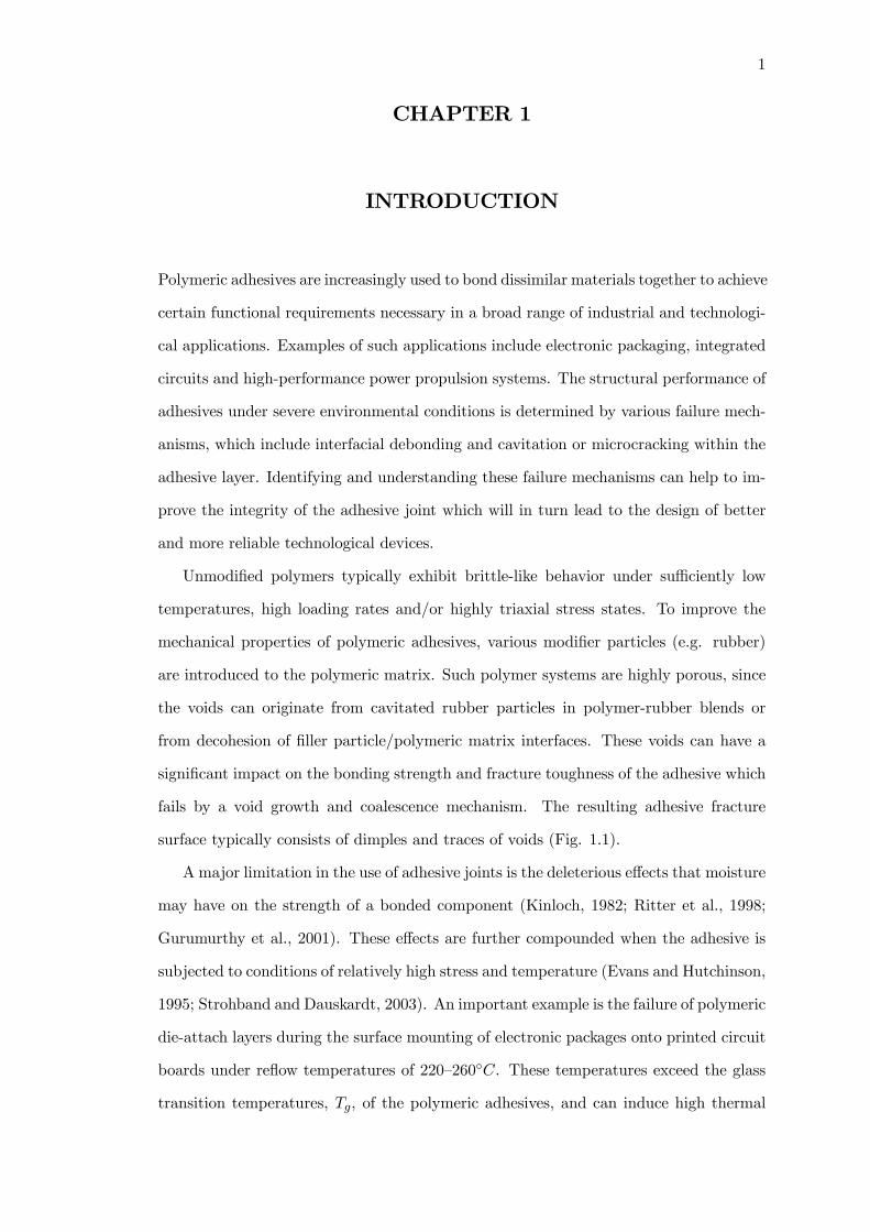
Polymeric adhesives are increasingly used to bond dissimilar materials together to achieve
certain functional requirements necessary in a broad range of industrial and technologi-
cal applications. Examples of such applications include electronic packaging, integrated
circuits and high-performance power propulsion systems. The structural performance of
adhesives under severe environmental conditions is determined by various failure mech-
anisms, which include interfacial debonding and cavitation or microcracking within the
adhesive layer. Identifying and understanding these failure mechanisms can help to im-
prove the integrity of the adhesive joint which will in turn lead to the design of better
and more reliable technological devices.
Unmodified polymers typically exhibit brittle-like behavior under sufficiently low
temperatures, high loading rates and/or highly triaxial stress states. To improve the
mechanical properties of polymeric adhesives, various modifier particles (e.g. rubber)
are introduced to the polymeric matrix. Such polymer systems are highly porous, since
the voids can originate from cavitated rubber particles in polymer-rubber blends or
from decohesion of filler particle/polymeric matrix interfaces. These voids can have a
significant impact on the bonding strength and fracture toughness of the adhesive which
fails by a void growth and coalescence mechanism. The resulting adhesive fracture
surface typically consists of dimples and traces of voids (Fig. 1.1).
A major limitation in the use of adhesive joints is the deleterious effects that moisture
may have on the strength of a bonded component (Kinloch, 1982; Ritter et al., 1998;
Gurumurthy et al., 2001). These effects are further compounded when the adhesive is
subjected to conditions of relatively high stress and temperature (Evans and Hutchinson,
1995; Strohband and Dauskardt, 2003). An important example is the failure of polymeric
die-attach layers during the surface mounting of electronic packages onto printed circuit
boards under reflow temperatures of 220—260◦C. These temperatures exceed the glass
transition temperatures, Tg, of the polymeric adhesives, and can induce high thermal
2
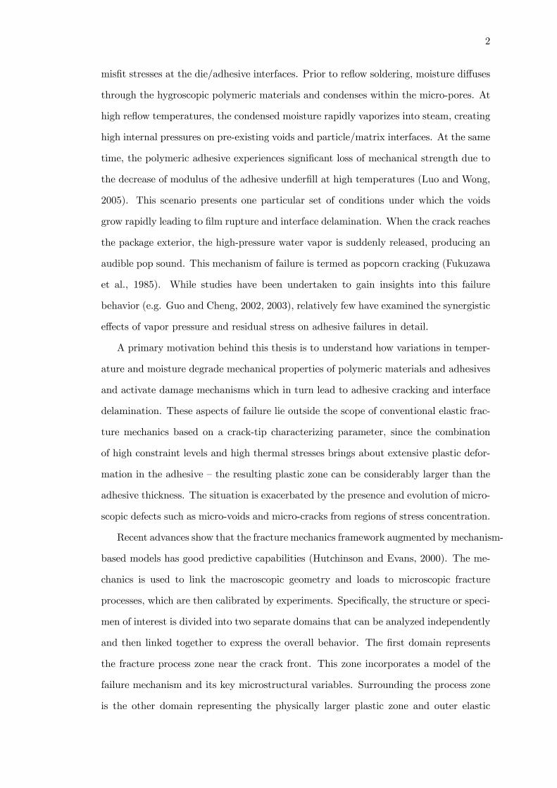
misfit stresses at the die/adhesive interfaces. Prior to reflow soldering, moisture diffuses
through the hygroscopic polymeric materials and condenses within the micro-pores. At
high reflow temperatures, the condensed moisture rapidly vaporizes into steam, creating
high internal pressures on pre-existing voids and particle/matrix interfaces. At the same
time, the polymeric adhesive experiences significant loss of mechanical strength due to
the decrease of modulus of the adhesive underfill at high temperatures (Luo and Wong,
2005). This scenario presents one particular set of conditions under which the voids
grow rapidly leading to film rupture and interface delamination. When the crack reaches
the package exterior, the high-pressure water vapor is suddenly released, producing an
audible pop sound. This mechanism of failure is termed as popcorn cracking (Fukuzawa
et al., 1985). While studies have been undertaken to gain insights into this failure
behavior (e.g. Guo and Cheng, 2002, 2003), relatively few have examined the synergistic
effects of vapor pressure and residual stress on adhesive failures in detail.
A primary motivation behind this thesis is to understand how variations in temper-
ature and moisture degrade mechanical properties of polymeric materials and adhesives
and activate damage mechanisms which in turn lead to adhesive cracking and interface
delamination. These aspects of failure lie outside the scope of conventional elastic frac-
ture mechanics based on a crack-tip characterizing parameter, since the combination
of high constraint levels and high thermal stresses brings about extensive plastic defor-
mation in the adhesive — the resulting plastic zone can be considerably larger than the
adhesive thickness. The situation is exacerbated by the presence and evolution of micro-
scopic defects such as micro-voids and micro-cracks from regions of stress concentration.
Recent advances show that the fracture mechanics framework augmented by mechanism-
based models has good predictive capabilities (Hutchinson and Evans, 2000). The me-
chanics is used to link the macroscopic geometry and loads to microscopic fracture
processes, which are then calibrated by experiments. Specifically, the structure or speci-
men of interest is divided into two separate domains that can be analyzed independently
and then linked together to express the overall behavior. The first domain represents
the fracture process zone near the crack front. This zone incorporates a model of the
failure mechanism and its key microstructural variables. Surrounding the process zone
is the other domain representing the physically larger plastic zone and outer elastic

3
region that can be described by continuum models of elastic-plastic behavior. Within
this framework, fracture resistance consists of two contributions: the intrinsic work of
separation in the process zone and the extrinsic plastic dissipation in the plastic zone.
This thesis adopts a mechanism-based failure model to study the role of residual
stress and vapor pressure on void growth and rupture in constrained adhesive films.
The model has been incorporated into a constitutive relation for porous materials, and
the augmented material model is then implemented into a nonlinear finite element code.
Background to the development of this model, together with a detailed literature review,
is provided in Chapter 2.
The research addresses several important aspects of adhesive failures. Chapter 3 ex-
amines the competing failure mechanisms in a polymeric adhesive with a centerline crack
sandwiched between elastic substrates. The adhesive film is stressed by remote loading
and residual stresses, while voids in the adhesive are pressurized by rapidly expanding
water vapor. The exhibited failure mechanisms include: (i) extended contiguous dam-
age zone emanating from the crack; (ii) multiple damage zones forming at distances of
several film thicknesses ahead of the crack; and (iii) extensive damage developing along
film-substrate interfaces. The effects of non-uniformity in the adhesive’s initial porosity
distribution on the failure mechanisms are also examined.
Crack growth computations are subsequently performed in Chapters 4 and 5 to study
the interfacial toughness in polymeric adhesive joints for two different crack geometries:
(a) parallel cracks along the film-substrate interfaces under mode I loading; and (b)
single film-substrate interfacial crack subjected to mixed mode loading. Finite element
predictions in these studies have provided new insights into adhesive failures under severe
humidity and temperature conditions. The model predictions were also found to be in
good agreement with published experimental results.
In contrast to the pressure-insensitive yielding and plastic incompressibility assump-
tion in classical metal plasticity, experimental studies have shown that the deformation
of polymeric materials is highly sensitive to hydrostatic pressure (e.g. Quinson et al.,
1997); some have observed that certain polymers exhibit modest levels of plastic dila-
tancy (e.g. G’Sell et al., 2002; Utz et al., 2004). Studies in this area have primarily
focused on the effects of pressure-sensitivity and plastic dilatancy on the crack-tip stress

4
Figure 1.1: Typical fracture surface for rubber-modified adhesive (Imanaka et al., 2003).
and deformation fields in unvoided polymers and adhesives (e.g. Li and Pan, 1990a, b;
Chowdhury and Narasimhan, 2000a, b; Subramanya et al., 2006). A clearer picture of
these distinctive characteristics of polymers can be obtained from the study of voided
materials, since typical polymer systems are highly porous.
In view of the above, efforts in this thesis have also been directed towards the micro-
mechanical analysis of porous pressure-sensitive dilatant polymers and adhesives. Chap-
ter 6 focuses on the void growth and interaction in pressure-sensitive dilatant materials
containing two size-scales of voids. The representative material volume is subjected to
physical stress states similar to highly stressed regions ahead of the crack. Building
on this knowledge, detailed two- and three-dimensional finite element computations are
performed in Chapters 7 and 8 to investigate the failure mechanisms in pressure-sensitive
dilatant adhesives. The damage process zone in these adhesives are explicitly modeled
using discrete voids to replicate the exact void growth behavior. The primary objective
is to ascertain how pressure-sensitivity and plastic dilatancy influence void growth and
coalescence ahead of a crack in polymeric adhesive joints, and how these parameters
contribute to the formation of extended damage zones.

5
The major findings of this research and recommendations for future work are sum-
marized in Chapter 9. While the subject of this research is relevant to a wide range
of industrial applications such as those mentioned above, strong emphasis in this thesis
is placed on adhesive failures in electronic packages in view of the rising trend towards
extreme miniaturization.

6
CHAPTER 2
BACKGROUND THEORY AND MODELING
The micromechanisms of fracture can be broadly classified into four categories: (i) duc-
tile fracture; (ii) cleavage fracture; (iii) intergranular fracture; and (iv) fatigue failure
(Anderson, 1995). In polymeric adhesive joints, the numerous pores and cavities ob-
served within the adhesive film as well as along the interfaces infers that ductile fracture
involving void growth and coalescence is the dominant failure mode.
2.1 Micromechanics of ductile fracture
Many ductile engineering materials contain voids, which originate from imperfections
during fabrication or from void nucleation at second-phase inclusions during deforma-
tion. In rubber modified epoxies, for example, the larger pores originate from cavitated
rubber blends or from the decohesion of filler particle/polymer matrix interfaces, while
the phenomenon of crazing can induce the formation of localized microporous zones.
When sufficient load is applied, the larger voids grow in tandem to the overall defor-
mation. A local zone of high stress concentration then emanates between these voids,
raising the stresses at the “sandwiched” micro-voids. Driven by stored elastic energy,
these micro-voids then undergo rapid plastic expansion. When the stress between these
voids reaches a critical level, the growth of a second set of micro-voids would initiate,
and the entire process repeats itself. As the voids grow and the mean spacing between
them shrinks to a critical size, the strain fields of the voids would start to interact. Neck-
ing occurs and the submicron ligament between the voids weakens and eventually fails
by microcleavage or shearing along crystallographic planes, thus forming a macro-crack.
Intense local stresses at this crack-tip would encourage further crack propagation by the
same void growth and coalescence mechanism described, ultimately leading to fracture.
An important aspect of ductile fracture is the cavitation instability phenomenon,
which is known as the rapid nucleation and growth of one or several voids in a solid
under sufficiently high hydrostatic stress. This rupture phenomenon was experimentally

7
observed in bonded rubber cylinders by Gent and Lindley (1959). A similar phenomenon
of rapid cavity growth causing failure of a lead wire bonded to a surrounding glass
cylinder was observed by Ashby et al. (1989). Dalgleish et al. (1988, 1989) and Reimanis
et al. (1990) conducted a series of experiments using ceramic plates sandwiching metal
foils. They showed that the constraint imposed by the stiff elastic substrates resulted in
high mean stresses at several foil thicknesses ahead of the crack-tip. When the interface
adhesion is strong and the foil thin, an array of cavities was found to nucleate and grow
at these highly stressed sites. This phenomenon was also observed in numerical studies
by Varias et al. (1991).
Huang et al. (1991) and Tvergaard et al. (1992) examined the cavitation states for a
spherical void in an infinite, remotely stressed elastic-plastic solid. They demonstrated
that the criterion for cavitation under multiaxial axisymmetric stressing depended on
the attainment of a critical value of the mean stress. Huang et al. (1996) showed that
this critical mean stress level decreases drastically as the void volume fraction increases.
Focusing on the thermal and moisture effects in electronic packages, Guo and Cheng
(2001) observed that the onset of unstable void growth was governed by a critical surface
traction, defined by the sum of the internal vapor pressure and externally applied stress.
In actual voided materials there is a distribution of void sizes, resulting from different
sizes of the inclusions at which the voids nucleate, different amounts of growth since
nucleation of each void, etc. Faleskog and Shih (1997) introduced a representative
material volume containing a single large void and a population of discrete microvoids
to understand the micromechanics of void growth. Final rupture was dominated by
a succession of rapidly growing microvoids, which involved the synergistic interaction
between elasticity associated with high stress triaxiality and stiffness softening caused by
plastic yielding. Tvergaard (1998) examined the behavior of very small voids growing
in the region between two larger voids, and affirmed the importance of plastic flow
localization in driving the cavitation of sufficiently small voids. Perrin and Leblond
(2000) performed an analytical study of void growth arising from two populations of
cavities of different size-scales. They observed that the smaller cavities in certain cases
could reach coalescence prior to the larger ones.

8
2.2 Mathematical models for void growth
Several analytical models have been developed to describe the evolution of void growth
and coalescence in ductile materials. The early works of McClintock (1968) and Rice and
Tracey (1969) derived mathematical relations for cylindrical and spherical void growth
in elasto-plastic solids. They suggested that the growth of voids depends on the imposed
equivalent plastic strain and the triaxiality ratio. Based on these concepts, Hancock and
Mackenzie (1976) proposed a simplified model, known as the Stress Modified Critical
Strain (SMCS) model, for capturing the ductile fracture mechanism in metals. They
assumed that ductile crack initiation occurs when the equivalent plastic strain exceeds
a critical value of the plastic strain corresponding to a critical void size. The SMCS
model accounts for the effects of stress triaxiality on void growth and coalescence, and
is also dependent on a length scale parameter.
The most widely known porous material model able to describe the plastic behavior
of voided materials under multi-axial load was put forth by Gurson (1977). A yield
condition, a flow law, a measure of void volume fraction, a rule for nucleating voids
and a law for the evolution of void volume fraction comprise the Gurson theory. The
Gurson model has a sound microstructural basis and key features of the model have been
validated by detailed finite element calculations and experiments on voided materials.
Tvergaard (1990) introduced two adjustment factors in the Gurson model to account for
the synergistic effects of void interactions and material strain hardening. Gologanu et al.
(1993, 1995) modified the Gurson model to account for void shape effects. More recently,
Guo and Cheng (2002) extended the Gurson model to incorporate vapor pressure as an
internal variable. Details on the extended Gurson model by Guo and Cheng (2002) are
provided at the end of Section 2.3.2.
2.3 Mechanism-based models
Mechanism-based computational models can link the microscopic fracture process of a
material to its macroscopic failure behavior, and are widely used in the prediction of
fracture and failure of structural components. Two well-known models are the traction-
separation relation and the cell element approach.

9
2.3.1 Traction-separation relation
The traction-separation relation was introduced by Needleman (1987) to study particle
debonding in metal matrices and subsequently by Tvergaard and Hutchinson (1992,
1994) to model crack growth resistance in homogeneous solids and along interfaces. A
traction-separation law simulating the fracture process is embedded within an elastic-
plastic continuum as a boundary condition along the line extending ahead of the crack.
This separation law, representing interface adhesion, is described by the peak traction of
the interface σ, and the work of separation per unit area Γ0. These two parameters may
be obtained by calibrating crack growth analysis curves to experimental measurements.
Once the parameters of the fracture process separation law are specified, the model can
be used to predict the relation between crack advance and applied stress. This method
was also employed by Tvergaard and Hutchinson (1996) and Strohband and Dauskardt
(2003) to study interface separation in residually-stressed thin film structures.
2.3.2 Cell element approach
Many metals which fail by void growth and coalescence display a macroscopically planar
fracture process zone of one or two void spacing in thickness. This zone is characterized
by intense plastic straining in the ligaments between voids which have undergone exten-
sive void growth. Away from this zone, little or no void growth is seen. Xia and Shih
(1995a) idealized the ductile fracture process by confining void growth and coalescence
to a material layer of initial thickness D ahead of the initial crack. This layer is mod-
eled by a single row of uniformly-sized cells. Each cell contains a void of initial volume
fraction f0, defined as the void volume over the cell volume. The Gurson’s relation
(Gurson, 1977) for dilatant plasticity was used to describe the progressive damage in
the cells resulting in material softening and, ultimately, loss of stress carrying capac-
ity. The material outside of this strip, known as the background material, was assumed
to be undamaged by void growth; its response was described by the J2 flow theory of
plasticity. A schematic of this model during crack growth is shown in Fig. 2.1.
Tvergaard and Hutchinson (1992) and Xia and Shih (1995b) have shown that large
inclusions as well as weakly bonded particles nucleate voids at stresses that are well
below those that develop ahead of the crack. For further simplification, one can neglect

10
the nucleation process and assume the voids to be pre-existing.
The cell element approach provides a unique concept for modeling ductile fracture.
When combined with finite element, a unified mathematical material model which can
give an accurate representation of this concept would provide the key to accurate pre-
diction of failure. Numerical aspects and calibration of the cell element approach are
discussed by Faleskog et al. (1998), and Gullerud et al. (2000). This methodology has
proven successful in predicting ductile crack growth in complex engineering applications
(Ruggieri et al., 1996).
Xia and Shih’s (1995a) cell element approach was motivated by ductile fracture in
metals. Imanaka et al. (2003) observed that the fracture surface of rubber-modified
epoxy resin under high stress triaxiality also consists of dimple surfaces and traces of
voids (Fig. 1.1). Away from the center of the crack-tip, void growth is suppressed. In
view of this, the applicability of the cell element approach can be extended to polymers.
A significant part of Chapters 3—5 is devoted to the study adhesive failures using
Xia and Shih’s methodology, where computational cells are deployed directly ahead of
the crack in the adhesive film. The behavior of these cell elements is described by the
Gurson flow potential Φ (Gurson, 1977; Tvergaard, 1990) extended to take account of
vapor pressure p (Guo and Cheng, 2002). It has the form:
Φ =³σeσ
´2+ 2q1f cosh
µ3q2 (σm + p)
2σ
¶−h1 + (q1f)
2i= 0 (2.1)
where σe denotes the equivalent macroscopic stress, σm the mean macroscopic stress
and σ the flow stress of the matrix. The micromechanics parameters q1 and q2 were
introduced by Tvergaard (1990) to improve model predictions for periodic arrays of
cylindrical and spherical voids.
Background Material
Background Material
fE f0
Cell Element
D
D
Figure 2.1: Schematic of the Cell Element Approach.

11
The vapor pressure, p, is a new internal variable given by
p
p0=
T
T0
f0f
1− f
1− f0e−3α∆T (2.2)
which relates the current state (p, f, T ) to the initial state (p0, f0, T0). In the above, α
is the coefficient of thermal expansion (CTE), ∆T is the temperature rise relative to
the reference temperature T0, and f is the current void volume fraction which obeys the
volumetric plastic strain rate relation
f = (1− f) trdp . (2.3)
For isothermal analysis, ∆T = 0. The extended Gurson model (2.1) together with (2.2)
and (2.3) describe the full process of void growth, coalescence and failure.
Detailed modeling of the fracture process zone using discrete voids will be carried
out in Chapters 7 and 8.
2.4 Pressure-dependent yielding
While the mechanical behavior of most metallic materials can be well described by
the von Mises yield criterion, experimental studies have shown that the deformation
of polymeric materials is highly sensitive to hydrostatic pressure (e.g. Quinson et al.,
1997; Spitzig and Richmond, 1979). The effect of pressure can be seen from the differ-
ence observed between the stress-strain curves under uniaxial tension and compression
(which are associated with a negative and positive pressure respectively), and also from
the increase in stress level with pressure in a constant strain rate test (Fig. 2.2). This
pressure-sensitive behavior is attributed to the reduction in molecular mobility by hy-
drostatic pressure (Hasan et al., 1993). Experimental results on certain metallic alloys
also reveal the dependence of yield stress on hydrostatic pressure, although to a lesser
extent compared to polymers (Spitzig and Richmond, 1984).
The above phenomenon can be explained by assuming a yield criterion based on
a combination of the mean stress and effective stress. For illustrative purposes, ex-
perimental data from a butt joint test for rubber-toughened adhesives by the National
Physics Lab, U.K., along with predictions using the von Mises and pressure-dependent
(Drucker-Prager) models, are shown in Fig. 2.3. Observe that the pressure-dependent
model provides quite a good fit to the experimental data for the polymeric adhesive.

12
(a) 360
340
320
300
280
260
240
220
200
180
160
140
120
100
80
60
40
20
0
50
45
40
35
30
25
20
15
10
5
00 0.05 0.10 0.15 0.20 0.25 0.30
Engineering Strain
Eng
inee
ring
Stre
ss, k
si
Eng
inee
ring
Stre
ss, M
Pa
(b)(a) 360
340
320
300
280
260
240
220
200
180
160
140
120
100
80
60
40
20
0
50
45
40
35
30
25
20
15
10
5
00 0.05 0.10 0.15 0.20 0.25 0.30
Engineering Strain
Eng
inee
ring
Stre
ss, k
si
Eng
inee
ring
Stre
ss, M
Pa
360
340
320
300
280
260
240
220
200
180
160
140
120
100
80
60
40
20
0
50
45
40
35
30
25
20
15
10
5
00 0.05 0.10 0.15 0.20 0.25 0.30
Engineering Strain
Eng
inee
ring
Stre
ss, k
si
Eng
inee
ring
Stre
ss, M
Pa
(b)
Figure 2.2: (a) Yield envelopes in the σ3 = 0 plane for PMMA at four temperatures(Quinson et al., 1997). (b) Effect of hydrostatic pressure on the compressive stress-straincurves of polycarbonate (Spitzig and Richmond, 1979).
In addition to pressure-sensitivity, studies have shown that the plastic flow of certain
polymers could be non-volume preserving (e.g. G’Sell et al., 2002; Utz et al., 2004). The
extent of plastic dilatancy of these materials, however, is overstated by an associated
flow rule (Chiang and Chai, 1994). This has motivated the use of a non-associated flow
rule in numerical studies by Chiang and Chai (1994) and Chowdhury and Narasimhan
(2000a), amongst others.
Numerical studies on crack-tip fields for homogeneous (unconstrained) pressure-
sensitive dilatant materials were conducted by Li and Pan (1990a, b) and Dong and
Pan (1991). They showed that increasing pressure-sensitivity reduces the magnitude
of hydrostatic stress ahead of the crack, and dramatically changes the size and shape
of the plastic zone. Chowdhury and Narasimhan (2000a) also observed that increasing
pressure-sensitivity in a constrained layer configuration relaxes the stress state ahead of
the crack, which could increase the fracture toughness of the layer. On the other hand,
Subramanya et al. (2006) demonstrated that pressure-sensitivity enhances the plastic
strain and crack opening displacements. These contrasting effects of pressure-sensitivity
could either hasten or retard ductile fracture.
13
0 10 20 30 400
5
10
15
20
25
30
35
Load
(kN
)
Extension (microns)
von Mises
Drucker-Prager
experimental data
0 10 20 30 400
5
10
15
20
25
30
35
Load
(kN
)
Extension (microns)
von Mises
Drucker-Prager
experimental data
Figure 2.3: Comparison of force/extension predictions with a typical experimental curvefor a butt joint (National Physics Lab, U.K.).
Chapters 6—8 focus on the effects of pressure-sensitivity on void growth and interac-
tion. The pressure-dependent behavior of the material is modeled by a linear combina-
tion of the mean stress and effective stress (Chiang and Chai, 1994; Jeong et al., 1994).
The yielding criterion is described by
σe + 3ασm − σ = 0 (2.4)
where σe is the effective stress, σm = σkk/3 the mean stress, σ the flow stress of the
subsequent yield surface, and α the pressure-sensitivity index. The friction angle ψα
can be defined by tanψα = 3α. The flow potential is assumed to take the form
Φ = σe + 3βσm (2.5)
where β is the index for plastic dilatancy, which is related to the dilation angle ψβ by
tanψβ = 3β. The Drucker-Prager yielding condition (2.4) together with the flow poten-
tial (2.5) can describe the pressure-sensitive dilatant behavior of the material (Drucker
and Prager, 1952). The plastic part of the deformation rate dp is given by the non-
associated flow rule
dp = ˙p∂Φ
∂σ(2.6)
where ˙p ≡q23ep : ep is the equivalent strain rate, in which ep signifies the deviatoric
part of dp. It reduces to an associated flow rule when α = β.
The flow stress σ is a function of the accumulated plastic strain p =R˙pdt. For a
14
power-law plastic hardening solid, one has
σ0E
µσ
σ0
¶1/N− σ
E= p (2.7)
where N is the hardening exponent ranging from 0 to 1, and σ0 the initial yield stress
under shear which is related to the initial tensile and compressive yield stresses σt0 and
σc0, by
σ0 =
⎧⎪⎨⎪⎩(1 + α)σt0 for tension
(1− α)σc0 for compression.(2.8)
The pressure-sensitivity index α can be determined by σt0 and σc0 as
α =σc0 − σt0σc0 + σt0
. (2.9)
The friction angle ψα of certain metallic alloys ranges between 0◦ and 8◦ (see Table 1 in
Stoughton and Yoon, 2004; Iyer and Lissenden, 2003). In polymeric materials, typical
ψα ranges between 0◦ and 23◦ (Quinson et al., 1997), with dilation angle ψβ between 0
◦
and ψα since plastic dilatancy is overstated by an associated flow rule.
2.5 Crazing
Crazes occur in many glassy polymers (i.e. amorphous polymers below their glass tran-
sition temperature Tg) after yielding during tensile deformation. Visually, crazes may
be observed as a whitening of the polymer which develops under stress. This whiten-
ing is caused by multiple reflections of light from the polymer/void interfaces in the
crazes. Microscopically, crazes are planar defects which consist of regions of polymer in
which the incipient crack is bridged by highly orientated material known as fibrils, in
a direction perpendicular to the direction of the crack. The presence of this void-fibril
network is revealed by transmission electron microscopy in Fig. 2.4 (Kambour and Rus-
sell, 1971). Observe that the boundary between the undeformed polymer and the craze
is very sharp. Other striking features of crazes include their high reflectivity, planarity,
and large ratio of area to thickness (Kambour, 1973; Passaglia, 1987). In fact, crazes
often cease to thicken beyond a certain distance away from the growing tip, with growth
rate in the craze plane much greater than that normal to the plane. Craze formation
is also essentially a process of plastic deformation in the tensile stress direction without
significant lateral contraction, giving rise to dilatational plastic flow.
15
Figure 2.4: One-half of a craze in homopolystyrene, with centre of the craze at left-handedge of top micrograph, and the right-hand craze tip at right side of bottom micrograph(Kambour and Russell, 1971).
While crazes are load bearing and are a major source of toughness for thermoplastics,
crack growth in glassy polymers is nearly always preceded by craze growth. This can
be attributed to the open voided structure of crazes, which provide potential nucleation
sites for cracks. To a large extent, the fracture properties of these polymers are linked to
the stress-induced growth and breakdown of crazes. The modeling of crazing is therefore
highly complex, since any criterion for brittle behavior must take into account not only
the critical stress for crazing but also the kinetics of the craze fibril breakdown, which
must necessarily precede crack nucleation.
2.5.1 Craze formation and growth
Craze formation is closely related to the combination of the presence of defects and the
stress state (Krishnamachari, 1993). In glassy thermoplastics, the microvoids nucleate

16
Crack Fibril deformation
MicrovoidformationCrack Fibril
deformation
Microvoidformation
Figure 2.5: Schematic illustration of the crazing mechanism (Krishnamachari, 1993).
from impurities, additives and other particulate matter at points of high stress concen-
tration. Initially, yielding takes place for the small volume of material in the peak stress
region. This is followed by rapid work hardening due to the high degree of orientation.
An increase in the applied stress then leads to a concentration of microvoids into bands
of fibrils which are known to exhibit extension ratios of up to 500% before breakage. The
voids and fibrils make up about 50% each by volume, and constitute a highly porous
material which is termed craze. On further stressing, a separation of the specimen will
occur through the crazed material. See illustration in Fig. 2.5.
In addition to externally applied loads, residual stresses resulting from the thermal
mismatch stresses between various interfaces can cause crazing. When coupled with
environmental effects such as the presence of moisture, the formation and growth of
surface crazes will be further accelerated, resulting in environmental stress cracking.
Environmental craze growth, however, does not occur if the stress intensity factor at the
crack-tip is below a critical level (Swallowe, 1999).
Since crazing requires void formation, a dilatational component of stress must be
involved. A well accepted craze yielding criterion under biaxial stress conditions was
proposed by Sternstein and Ongchin (1969) as follows:
σ1 − σ2 º A(T ) +B(T )
σ1 + σ2(2.10)
where σ1 and σ2 are the largest and smallest principle stress components in the polymer,
and A(T ) and B(T ) the temperature dependent constants. The term B(T )σ1+σ2
is associated
with a dilatation of the material that results in an increase in flow mobility and thus
allows flow under the action of the deviatoric stress component, σ1−σ2. A schematic of

17
Pure shear
Yield
Craze
Pure shear
Yield
Craze
Figure 2.6: Biaxial stress envelopes for craze initiation and yielding (Sternstein andOngchin, 1969).
the craze envelope superimposed on the von Mises envelope is shown in Fig. 2.6. Note
that the σ1 + σ2 = 0 line is an asymptote to the craze curve. Below this line, crazes
cannot occur since a hydrostatic tensile stress component is required.
2.5.2 Micromechanical modeling
Experimental studies by Kramer (1983) and Passaglia (1984) suggest that under monotonic
tensile loading, the crazing stress σd along the craze-bulk interface is approximately
uniform, similar to that postulated in the Dugdale model (Dugdale, 1960). This ap-
proximate constant stress over the face of the craze motivates the use of the Dugdale
model to calculate the craze opening displacement, which traditionally is used as the
failure criterion for the craze. However, the constant crazing stress assumption implied
the absence of any stress concentration inside the craze, which meant that the craze
could draw indefinitely.
The above paradox was resolved by Brown (1991). Noting the experimental observa-
tions of Behan et al. (1975) which revealed the existence of short fibrils running between
the main tensile fibrils, Brown (1991) demonstrated that these “cross-tie” fibrils could
transfer load between the main fibrils. He pointed out that this load transfer mecha-
nism allows the normal forces in the fibrils directly ahead of the crack-tip to reach the

18
breaking force of the chain and hence cause the failure of the crack. Brown (1991) then
derived a mathematical description of the local fibril peak stress near the true crack-tip,
accounting for both the microstructural details of the craze as well as its thickness, and
drew conclusions on fibril breakage and polymer fracture energy. Subsequent studies by
Hui et al. (1992) and Sha et al. (1995, 1997, 1999) derived more detailed and accurate
solutions.
To bridge the gap between fundamental knowledge of craze micromechanics and
the role of crazing in polymer fracture, Tijssens et al. (2000a, b) developed a new
cohesive surface model, viz. an elastic viscoplastic traction-separation relation, which
accounts for the three separate stages of craze-initiation, widening, and breakdown.
This cohesive surface model was later employed by Estevez et al. (2000) to study the
interaction between plastic flow and crazing for an initially blunt crack under mode I
loading. Gearing and Anand (2004) presented an alternative continuum constitutive
relation to model the competition between shear-yielding and crazing. These studies
have provided the framework for the quantitative prediction of the deformation and
fracture response of glassy polymers.
2.5.3 Pressure-sensitivity effects
As mentioned earlier, pressure-sensitive yielding and craze formation are characteris-
tics unique to polymers. Some preliminary understanding of the correlation between
pressure-sensitivity and the craze zone length can be obtained from the Dugdale strip
yield model (Dugdale, 1960), which assumes a long slender plastic zone at the crack-
tip in a nonhardening pressure-insensitive material (α = 0). Here, the crazing zone is
assumed to be in the shape of a narrow plastic strip located in the plane of the crack.
Thin and long fibrils that bridge the crack surfaces grow like micro necks, each fibril is
subjected to uniaxial tensile stress σd. The craze zone length L is given by the Dugdale
model as
L =π
8
µKI
σd
¶2. (2.11)
For the pressure-sensitive material in (2.4), the tensile stress σd at yielding is σd =
σ0/ (1 + α). Denoting L0 as the plastic zone size corresponding to α = 0, i.e. σd = σ0,

19
(2.11) can be rewritten in the form
L/L0 = (1 + α)2 . (2.12)
Clearly, one can see that an increase in pressure-sensitivity α strongly increases the zone
length L. Observe from (2.12) that an increase in friction angle ψα (= tan−1 3α) from
0◦ to 20◦ increases the damage zone length by about 25%.
While the subject of crazing is not the primary motivation behind this thesis, some
insights into the effects of pressure-sensitivity and dilatancy on crazing in highly con-
strained polymers can be obtained from Chapters 7 and 8. The reader should be mindful
that these studies do not account for craze-fibril formation and subsequent breakdown.
20
CHAPTER 3
MECHANISMS OF FAILURE FOR ADHESIVE LAYER
WITH CENTERLINE CRACK
Research scope
Initial porosity and vapor pressure effects on the adhesive failure mechanisms havebeen previously documented by use of a partially porous adhesive model. This chapteradopts a fully porous adhesive model which allows for a competition between possiblefailure mechanisms under the influence of vapor pressure, residual stress, and non-uniform initial porosity distribution.
Main findings
Three potential failure mechanisms have been identified: (i) extended contiguous dam-age zone emanating from the crack; (ii) multiple damage zones forming at distancesof several film thicknesses ahead of the crack; and (iii) extensive damage developingalong film-substrate interfaces. The operative mechanism is dependent on the initialporosity level/distribution in the adhesive as well as the residual stress and vaporpressure levels.
Extracts from this chapter can be found in Journal Papers [2, 7] and Conference Papers[3, 6].
3.1 Introduction
Surface-mount plastic encapsulated microcircuits (PEM) are susceptible to several types
of temperature- and moisture-induced interface delamination and package cracking dur-
ing the reflow soldering process (Omi et al., 1991). See schematic in Fig. 3.1. In type
I, the package crack originates from the die pad/molding compound interface delami-
nation. In type II, the package crack originates from the die attach/die pad interface
delamination. Type III refers to package cracking originating from the die surface/mold
compound interface delamination. Of the three, type II package cracking is least re-
ported and understood. This study aims to gain some understanding of type II crack-
ing, with particular attention to vapor pressure and residual stress effects on die attach
failure.
Computational studies on the failure of polymeric adhesives taking into account

21
Molding compound Die Die-attach
Die-pad
TYPE I Cracking
TYPE II Cracking
TYPE III Cracking
Figure 3.1: Three types of package cracks. (a) Type I; (b) Type II; (c) Type III.
of vapor pressure effects were made by Guo and Cheng (2003). The study described
the interplay between stress elevation induced by constrained plastic flow and stress
relaxation associated with vapor pressure assisted void growth and coalescence. Voiding
activity takes place through three competing failure mechanisms: near-tip void growth
and coalescence with the crack; void growth with formation of an extended damage zone
emanating from the crack; and rapid void growth at large distances ahead of the crack
leading to formation of multiple damaged zones. In their work, Guo and Cheng used
a “partially porous adhesive” model wherein damage was confined to a well-delineated
zone in the adhesive, viz. a single row of void-containing cells deployed directly ahead
of the crack. Some background to the model can be found in Chapter 2.
Typical polymeric adhesives contain numerous pores and cavities of various size
scales (see Fig. 3.2). This suggests that the whole polymeric adhesive could be treated
as a porous material for purposes of studying damage arising from void growth and
coalescence. Moreover, related studies showed that crack growth can occur at the crack
front or along film/substrate interfaces (e.g. Chowdhury and Narasimhan, 1995, 2000a).

22
Figure 3.2: Porosity distribution in a typical Ball Grid Array package (Trigg, 2003).
Thus it appears that competition between different failure mechanisms could not be
addressed by the partially porous adhesive model used in previous studies. Guided by
these observations, this chapter makes use of a “fully porous adhesive” model where
pre-existing voids are distributed throughout the adhesive. Using this model, the effects
of vapor pressure, residual stress, adhesive porosity, and non-uniform initial porosity
distribution on the outcome among competing failure mechanisms are investigated. The
porous adhesive is described by an extended Gurson model incorporating vapor pressure
effects (Guo and Cheng, 2002).
3.2 Modeling aspects
This section describes the problem formulation and material parameters for the small-
scale yielding analysis. Numerical details on the model implementation of vapor pressure
and residual stress will be presented.
3.2.1 Adhesive properties
As a first step towards understanding popcorn cracking, moisture analysis was carried
out to determine the maximum possible water weight gain per sample volume for a par-
ticular ambient condition by measuring the saturation concentration data, e.g. Galloway
and Miles (1997) for plastic ball grid array (PBGA) packages. The saturated concen-
tration of moisture in BT (bimaleimide triazine) epoxy is 0.0066 g/cm3 at equilibrium
for the 23◦C / 70% relative humidity condition whereas in the die attach it is 0.017
g/cm3. Such large levels of condensed moisture suggest the materials in question are
highly porous. For typical polymeric adhesives, the estimated void volume fractions,

23
Figure 3.3: Typical solder reflow temperature profile.
from available moisture analysis, range from 1% to 5%. The highly porous nature of
adhesives in flip-chip-on-board (FCOB) and PBGA packages was also observed by Trigg
(2003) using infrared microscopy (Fig. 3.2).
In a humid environment, moisture diffuses to the voids in the adhesive. During
reflow soldering, surface mount plastic encapsulated devices are exposed to temperatures
between 210◦C to 260◦C for periods of 30 seconds to 5 minutes. Such temperatures fall
near the glass transition temperature Tg of the polymeric materials. An example of a
typical solder reflow temperature profile is shown in Fig. 3.3. The mechanical properties
of polymeric materials are highly sensitive to temperature. For example, the behavior
of epoxy at the temperatures of interest is listed below:
E = 3 GPa, σ0 = 30− 80 MPa at room temperature (25◦C);
E = 300 MPa, σ0 = 2− 5 MPa at reflow temperature (220◦C).(3.1)
These values are obtained from a modulus diagram for amorphous polymers (e.g. Fig.
3.4 in Gibson and Ashby, 1997).
Under these conditions, the condensed moisture vaporizes with little time for the
moisture or vapor to escape. The fast ramp rate suggests the effects of time-dependent
void growth to be small. The rapidly expanding water vapor exerts internal pressures
on the voids that could reach 3-6 MPa (Liu and Mei, 1995). Such stress levels are
comparable to the yield strengths of epoxy molding compounds and epoxy adhesives as
listed in (3.1). Other studies indicate that the thermal expansion mismatch between the

24
Figure 3.4: An adhesive (with a centerline crack) bonded to two elastic substratessubject to remote elastic KI field.
adhesive and the die can generate stresses exceeding the yield strength of the adhesive
(Evans and Hutchinson, 1995; Tvergaard and Hutchinson, 1996).
3.2.2 Material model
This chapter addresses the competing failure mechanisms in symmetrically loaded joints.
The adhesive contains a centerline crack which is long compared to the thickness of the
adhesive, h, as well as the extent of the plastic zone that develops in the adhesive. Under
these conditions, the asymptotic problem shown in Fig. 3.4 is applicable. Similar model
problems (same domains but with different initial crack configurations) are adopted
study the interfacial toughness of adhesive joints in Chapters 4 and 5.
The two substrates have identical properties. They are elastic isotropic materials
with Young’s modulus, Es, and Poisson’s ratio, νs. The adhesive is elastically isotropic
with Young’s modulus E and Poisson’s ratio ν. The plastic response of the adhesive is
characterized by a J2 flow theory (isotropic hardening based on Mises yield condition).
The uniaxial tensile stress-strain behavior of the adhesive is described by a true stress-
logarithmic strain relation
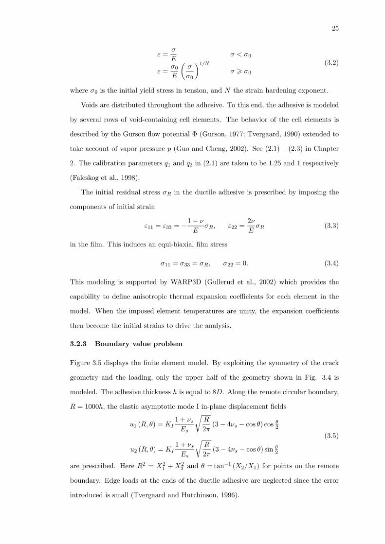
25
ε =σ
Eσ < σ0
ε =σ0E
µσ
σ0
¶1/Nσ > σ0
(3.2)
where σ0 is the initial yield stress in tension, and N the strain hardening exponent.
Voids are distributed throughout the adhesive. To this end, the adhesive is modeled
by several rows of void-containing cell elements. The behavior of the cell elements is
described by the Gurson flow potential Φ (Gurson, 1977; Tvergaard, 1990) extended to
take account of vapor pressure p (Guo and Cheng, 2002). See (2.1) — (2.3) in Chapter
2. The calibration parameters q1 and q2 in (2.1) are taken to be 1.25 and 1 respectively
(Faleskog et al., 1998).
The initial residual stress σR in the ductile adhesive is prescribed by imposing the
components of initial strain
ε11 = ε33 = −1− ν
EσR, ε22 =
2ν
EσR (3.3)
in the film. This induces an equi-biaxial film stress
σ11 = σ33 = σR, σ22 = 0. (3.4)
This modeling is supported by WARP3D (Gullerud et al., 2002) which provides the
capability to define anisotropic thermal expansion coefficients for each element in the
model. When the imposed element temperatures are unity, the expansion coefficients
then become the initial strains to drive the analysis.
3.2.3 Boundary value problem
Figure 3.5 displays the finite element model. By exploiting the symmetry of the crack
geometry and the loading, only the upper half of the geometry shown in Fig. 3.4 is
modeled. The adhesive thickness h is equal to 8D. Along the remote circular boundary,
R = 1000h, the elastic asymptotic mode I in-plane displacement fields
u1 (R, θ) = KI1 + νsEs
rR
2π(3− 4νs − cos θ) cos θ2
u2 (R, θ) = KI1 + νsEs
rR
2π(3− 4νs − cos θ) sin θ
2
(3.5)
are prescribed. Here R2 = X21 + X2
2 and θ = tan−1 (X2/X1) for points on the remote
boundary. Edge loads at the ends of the ductile adhesive are neglected since the error
introduced is small (Tvergaard and Hutchinson, 1996).

26
Figure 3.5: Finite element mesh for small scale yielding analysis. (a) Mesh of outerregion. (b) Refined mesh of inner region. (c) Near-tip mesh with several layers ofvoid-containing cell elements (D/2 by D/2). Cell is characterized by f0 and p0.

27
The computations are carried out using the finite element programWARP3D (Gullerud
et al., 2002). The finite element computational model consists of 2,257 three-dimensional,
8-node linear elements (two-dimensional plane strain elements are not included in the el-
ement library offered by WARP3D). Plane strain conditions are achieved by prescribing
out-of-plane displacements on all the nodes to vanish. The upper half of the adhesive
is modeled by eight rows of void-containing cell elements (see Fig. 3.5c). Each cell
element, of dimensions D/2 by D/2, has a void of initial volume fraction f0 associated
with initial vapor pressure p0. Hereafter, this computational model is referred to as the
fully porous adhesive (FPA) model.
For comparison purposes, computations were also performed in which void growth
is confined to a narrow zone directly ahead of the crack. In this case, only one row of
void-containing cell elements, each of dimension D/2 by D/2, is deployed ahead of the
crack. This partially porous adhesive (PPA) model is similar to the geometric models
employed by Guo and Cheng (2003) for damage evolution simulations and by Xia and
Shih (1995a) for crack growth studies. The void-free adhesive material is described by
(3.2).
For the crack geometry depicted in Fig. 3.4, Irwin’s relation between the stress
intensity factor KI and the energy release rate G for a plane strain crack in an elastic
solid is
G =1− ν2sEs
K2I . (3.6)
Small-scale yielding conditions prevail when the plastic zone size in the adhesive is
small compared to the distance to the remote boundary R. In this case, the J-integral
can be interpreted as the remote/applied energy release rate G. At various stages of
loading, the value of the J-integral is calculated on a number of contours around the
crack using the domain integral method (Moran and Shih, 1987). The domain integral
value is found to be in good agreement with the value given by (3.6). This consistency
check assures that small-scale yielding conditions are satisfied.
3.3 Uniform initial porosity distribution
In this section, void-containing cells of constant initial porosity are assumed to be uni-
formly distributed throughout the entire film.

28
From dimensional considerations, the spatial distribution of field quantities σm/σ0
and f depends on the following dimensionless geometric-material parameters:
J
σ0h,h
D;σ0E,Es
E,N, ν, νs; f0,
p0σ0
,σRσ0
. (3.7)
The properties of the elastic-plastic adhesive are specified by the parameters σ0/E =
0.01, ν = 0.4, and N = 0.1. Unless otherwise stated, the same material parameters are
also defined for the adhesives in Chapters 4 and 5. A typical level of elastic modulus
mismatch between the adhesive and the substrate considered is Es/E = 10, with νs =
0.3. Attention is directed towards the process related parameters below:
f0,p0σ0
,σRσ0
. (3.8)
3.3.1 Failures of low and high porosity adhesives
Sources that contribute to the initial porosity of an adhesive include the pre-existing
pores/cavities in the adhesive and filler particles that are weakly bonded to the polymeric
matrix. Results for the fully porous adhesive (FPA) are first presented.
Figure 3.6a displays the evolution of f for a low porosity adhesive, f0 = 0.01, under
pure remote loading. At applied load of J/(σ0h) = 0.082, the solid line labeled 0.082
shows voids adjacent to the crack-tip growing rapidly with near-tip f reaching about
0.1. At the same time, a second and smaller peak (f = 0.03) in void activity can be
found at distance X1 = 1.5h ahead of the crack. When the load is increased slightly
to J/(σ0h) = 0.089, there is a sudden burst in void activity. Voids in the vicinity of
X1 = 1.5h grow rapidly to levels well beyond f = 0.1. At even higher loadings not
shown here, the highly damaged zone centered about X1 = 1.5h joins with the crack
front. Concurrently, new zones of voiding are formed even further ahead of the crack.
To provide a more complete picture of the above sequence of void activity, the stress
profiles corresponding to J/(σ0h) = 0.082, and 0.089 shown in Fig. 3.6b are next
examined. The solid line labeled 0.082 shows the build up of the mean stress associated
with constrained plastic flow. At a higher load level of J/(σ0h) = 0.089, stresses in
vicinity of X1 = 1.5h fall sharply. The stress relaxation, extending over a spatial interval
of about 2h, is associated with rapid void growth centered aboutX1 = 1.5h shown in Fig.
3.6a. The solid lines in Fig. 3.6a and 3.6b depict the interplay between stress elevation

29
Figure 3.6: Porosity f and mean stress σm/σ0 ahead of crack (X2 = 0); f0 = 0.01,remote load only.
induced by constrained plastic flow and stress relaxation associated with extensive void
growth. The figure also shows that voiding occurs in a particular sequence — voiding
begins near the crack-tip followed by accelerated void growth at large distances ahead
of the crack. This voiding pattern is referred to as “multiple damage zone” mechanism.
At this juncture, results for the FPA model are compared against the partially porous
adhesive (PPA) model adopted by Guo and Cheng (2003) for adhesive failure. The
porosity distribution shown by the dashed curves in Fig. 3.6a and 3.6b are obtained
using the PPA model. It is noteworthy that the sequence of voiding and its patterns
(dashed lines) for the PPA are similar to those for the FPA (solid lines). However, at
comparable load levels, the PPA model overestimates the damage ahead of the crack.
Figure 3.7 presents results for a high porosity adhesive, f0 = 0.05. Results for the

30
Figure 3.7: Porosity f and mean stress σm/σ0 ahead of crack (X2 = 0); f0 = 0.05,remote load only.
FPA are taken up first. A zone of voiding emanates from the crack at low load — see
solid curve labeled by 0.044 in Fig. 3.7a. The corresponding stress distribution is shown
in Fig. 3.7b — see solid curve labeled by 0.044. As the load increases, voids further ahead
of the crack also grow by significant amounts — see solid curve labeled by 0.066. The
stress relaxation associated with this pattern of voiding shifts the peak stress location
further ahead of the crack — from X1 = 0.5h to X1 = 3h. The distance between the peak
stress location and the crack-tip demarcates the physical extent of the damage zone. At
J/(σ0h) = 0.066, the damage zone extends over a distance 3h ahead of the crack. This
pattern of adhesive failure is referred to as “contiguous damage zone” mechanism.
Void growth and stress distributions predicted by the PPA model are shown by
dashed lines in Fig. 3.7. While the pattern of voiding is similar to that for the FPA

31
Figure 3.8: Porosity f ahead of crack (X2 = 0) and along adhesive/substrate interface(X2 = 0.5h) under four types of loading. f0 = 0.01, (i) remote load only; (ii) p0 =σ0, σR = 0; (iii) σR = σ0, p0 = 0; (iv) p0 = σR = σ0.
model, the PPA model overestimates damage levels directly ahead of the crack.
The porosity profiles in Figs. 3.6 and 3.7 reveal a crucial character of adhesive
damage. The damage zone size is a nonlinear function of the applied load — a small load
increment can cause a disproportionately large increase in the damage zone size. For
example, a fifty percent increase in the load (from 0.044 to 0.066) produces a sixfold
increase in the size of the damage zone (from 0.5h to 3h, see Fig. 3.7).
3.3.2 Temperature/moisture effects on failures of low porosity adhesives
Vapor pressure and residual stress effects on damage in low porosity adhesives are taken
up here. High residual stresses, comparable to the adhesive’s yield strength, are not un-
common in IC packages where adhesives are deposited at elevated temperatures. Evans

32
and Hutchinson (1995), Huang et al. (1996) and Guo and Cheng (2001) have discussed
residual stress effects on voiding and interface cracking. Tvergaard and Hutchinson
(1996) showed that residual tensile stresses in a ductile adhesive can lower the joint
toughness significantly.
Moisture resides in pores and cavities of adhesives as well as at adhesive/particle and
adhesive/die interfaces. During the reflow soldering process, the condensed moisture
vaporizes. The rapidly expanding water vapor generates internal pressures (on the
voids) that can reach 3-6 MPa. These levels are comparable to the yield strengths of
the adhesives when the reflow soldering temperature exceeds the adhesive’s Tg.
Results for a low porosity adhesive, f0 = 0.01, are first presented. The stress arising
from thermal expansion mismatch between the adhesive and the substrate is treated as
an initial residual tensile stress of magnitude σR = σ0. Rapid vaporization of moisture at
high temperature introduces an initial vapor pressure on the void of magnitude p0 = σ0.
Figure 3.8a displays the damage distribution, at J/(σ0h) = 0.060, under four types
of loading: (i) remote load only; (ii) remote load with vapor pressure (p0 = σ0); (iii)
remote load with residual stress (σR = σ0); (iv) remote load with vapor pressure and
residual stress (p0 = σR = σ0). With the exception of loading type (iii), damage by void
growth under the other three load types is concentrated in the zone directly ahead of
the crack.
Figure 3.8b shows the damage distribution at J/(σ0h) = 0.088. As noted in the
previous section in connection with Fig. 3.6, the multiple damage zone mechanism
prevails under load type (i). Contiguous damage zones are formed under load types (ii)
and (iv).
Under load type (iii), voids near the mid-plane (X2 = 0) experienced relatively little
growth whereas voids at the adhesive/substrate interface grow rapidly. The dash lines in
Figs. 3.8a and 3.8b depict the progression of voiding at the adhesive/substrate interface
(X2 = 0.5h).
Figure 3.9 displays contour maps of void activity associated with load types (i)
through (iv). Three distinctive damage patterns can be seen. The topmost plot displays
contours of f = 0.05 under load type (i). At J/(σ0h) = 0.070 voiding occurs near the
tip. At J/(σ0h) = 0.088, intense voiding activity develops far ahead of the crack with
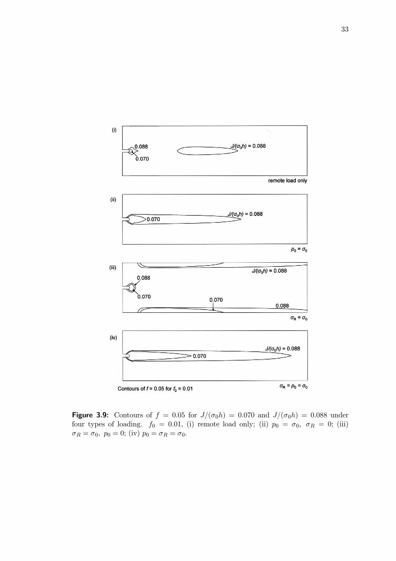
33
Figure 3.9: Contours of f = 0.05 for J/(σ0h) = 0.070 and J/(σ0h) = 0.088 underfour types of loading. f0 = 0.01, (i) remote load only; (ii) p0 = σ0, σR = 0; (iii)σR = σ0, p0 = 0; (iv) p0 = σR = σ0.

34
Figure 3.10: Mean stress under four types of loading for f0 = 0.01. (a) and (b) Stressahead of crack (X2 = 0); (i) remote load only; (ii) p0 = σ0, σR = 0; (iv) p0 = σR = σ0.(c) Stress along adhesive/substrate interface (X2 = 0.5h); (iii) σR = σ0, p0 = 0.

35
Figure 3.11: Porosity f ahead of crack (X2 = 0) under four types of loading. f0 = 0.05,(i) remote load only; (ii) p0 = σ0, σR = 0; (iii) σR = σ0, p0 = 0; (iv) p0 = σR = σ0.
the new damage zone being centered about X1 = 1.5h (compare with profile of solid line
in Fig. 3.8b). At even higher loads, additional zones of void activity form even further
ahead of the crack. This pattern of voiding has been referred to as multiple damage
zone mechanism.
The second and fourth plots show extended damage zones emanating from the crack
at J/(σ0h) = 0.070 and 0.088. The voiding pattern that develops under load type (ii)
and (iv) belong to the contiguous damage zone mechanism.
The third plot shows void growth occurring near the crack-tip as well as along the
adhesive/substrate interfaces under load type (iii). At both load levels, J/(σ0h) = 0.070
and 0.088, voiding occurs primarily along the adhesive-substrate interface with peak
porosities developing at about 45◦ to the initial crack-tip.
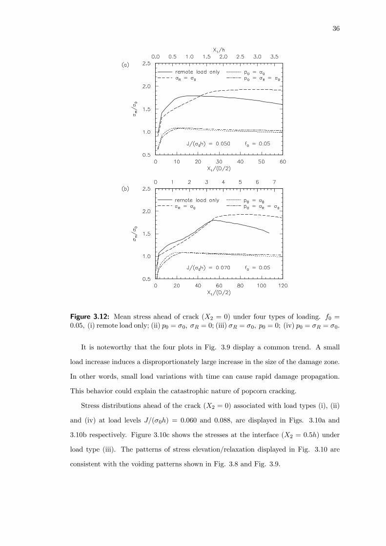
36
Figure 3.12: Mean stress ahead of crack (X2 = 0) under four types of loading. f0 =0.05, (i) remote load only; (ii) p0 = σ0, σR = 0; (iii) σR = σ0, p0 = 0; (iv) p0 = σR = σ0.
It is noteworthy that the four plots in Fig. 3.9 display a common trend. A small
load increase induces a disproportionately large increase in the size of the damage zone.
In other words, small load variations with time can cause rapid damage propagation.
This behavior could explain the catastrophic nature of popcorn cracking.
Stress distributions ahead of the crack (X2 = 0) associated with load types (i), (ii)
and (iv) at load levels J/(σ0h) = 0.060 and 0.088, are displayed in Figs. 3.10a and
3.10b respectively. Figure 3.10c shows the stresses at the interface (X2 = 0.5h) under
load type (iii). The patterns of stress elevation/relaxation displayed in Fig. 3.10 are
consistent with the voiding patterns shown in Fig. 3.8 and Fig. 3.9.

37
3.3.3 Temperature/moisture effects on failures of high porosity adhesives
Results for a high porosity adhesive, f0 = 0.05, are presented in this section. Figure
3.11a and 3.11b display the voiding profiles at J/(σ0h) = 0.050 and 0.070, respectively.
Voiding activity, under all four load types, is concentrated in the zone directly ahead of
the crack. The pattern of voiding belongs to the contiguous damage zone mechanism.
Figure 3.12 shows stress elevation/relaxation under the four load types. The stress
distributions for load types (i) and (iii) display the elevation/relaxation characteristics
seen in Figs. 3.7 and 3.10. By contrast stress distributions, associated with load types
(ii) and (iv), over the entire damage zone are relatively uniform. This suggests that
stress relaxation is balanced by stress elevation — a behavior that appears to be peculiar
to high porosity adhesive subjected to high vapor pressure.
3.4 Non-uniform initial porosity distribution
The analyses in the previous section assume the initial porosity in the adhesive to be
constant. The porosity distributions in typical adhesives are likely to be non-uniform.
In this section, the non-uniform initial porosity distribution in the adhesive is described
by a doubly-periodic function
f i,j0 = f0 +∆f0 cos¡2πXi
1/h¢cos³2πXj
2/h´
(3.9)
where f0 is the mean porosity, ∆f0 the amplitude of the non-uniformity which satisfies
the limits 0 ≤ ∆f0/f0 ≤ 1, and the indices i, j represent the element number in the X1and X2 directions respectively. A schematic of the initial porosity distribution governed
by the above doubly-periodic function is shown in Fig. 3.13. The associated initial
vapor pressure p0 is constant over the cells in the adhesive.
3.4.1 Failures of low and high porosity adhesives
Figure 3.14 shows the contour maps of void activity for low mean porosity adhesives with
f0 = 0.01. Contours of f = 0.05 are displayed for fixed load levels of J/(σ0h) = 0.088 and
0.094. For a uniform initial porosity distribution ∆f0/f0 = 0, the high stress triaxiality
in the adhesive drives the formation of a dominant damage zone some distances ahead
of the crack. With an increase in the amplitude of non-uniformity ∆f0/f0, the number
of unconnected damage sites correspondingly increases. For ∆f0/f0 = 0.3 in Fig. 3.14b,

38
Figure 3.13: Schematic of non-uniform initial porosity distribution in the adhesive film.
the primary damage site still occurs along the crack plane some distances ahead of the
crack-tip. The size of this damage zone, however, is comparatively smaller than for
∆f0/f0 = 0 in Fig. 3.14a. In addition, some unconnected damage zones are formed
both in front and behind of this primary voiding zone. For larger ∆f0/f0 of 0.6 in Fig.
3.14c, multiple damage zones are formed within the adhesive. Unlike Figs. 3.14a and
3.14b, these voiding sites are no longer directly ahead of the crack, but are located along
X2 = ±1/4h. At even higher loads, additional damage zones are formed even furtheraway from the crack-tip.
Figure 3.15 displays the contour maps of void activity f = 0.1 for high mean porosity
adhesives f0 = 0.05, with three amplitudes of non-uniformity: ∆f0/f0 = 0, 0.3 and 0.6.
For ∆f0/f0 = 0, the voiding pattern that develops belongs to the contiguous damage
zone mechanism. At the same load levels, contour maps for ∆f0/f0 = 0.3 show a
small concentrated voiding region emanating from the crack-tip, with some sporadic
unconnected damage sites developing further from the crack. For∆f0/f0 = 0.6, multiple
damage sites are formed both near and far away from the crack. The damage zones are
considerably smaller than for ∆f0/f0 = 0 and 0.3, which therefore suggests that less
concentrated voiding occurs in the adhesive. In addition, the location of these voiding
sites now span over a much larger region from the crack-tip.
As shown above, the formation of multiple damage zones in both high and low mean
porosity adhesives is closely linked with the doubly-periodic initial porosity distribution
governed by Eq. (3.9). Initiation of voiding begins at locations of maximum f0 — these
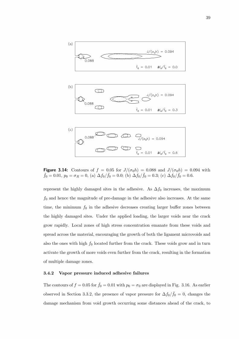
39
Figure 3.14: Contours of f = 0.05 for J/(σ0h) = 0.088 and J/(σ0h) = 0.094 withf0 = 0.01, p0 = σR = 0, (a) ∆f0/f0 = 0.0; (b) ∆f0/f0 = 0.3; (c) ∆f0/f0 = 0.6.
represent the highly damaged sites in the adhesive. As ∆f0 increases, the maximum
f0 and hence the magnitude of pre-damage in the adhesive also increases. At the same
time, the minimum f0 in the adhesive decreases creating larger buffer zones between
the highly damaged sites. Under the applied loading, the larger voids near the crack
grow rapidly. Local zones of high stress concentration emanate from these voids and
spread across the material, encouraging the growth of both the ligament microvoids and
also the ones with high f0 located further from the crack. These voids grow and in turn
activate the growth of more voids even further from the crack, resulting in the formation
of multiple damage zones.
3.4.2 Vapor pressure induced adhesive failures
The contours of f = 0.05 for f0 = 0.01 with p0 = σ0 are displayed in Fig. 3.16. As earlier
observed in Section 3.3.2, the presence of vapor pressure for ∆f0/f0 = 0, changes the
damage mechanism from void growth occurring some distances ahead of the crack, to

40
Figure 3.15: Contours of f = 0.1 for J/(σ0h) = 0.053 and J/(σ0h) = 0.070 withf0 = 0.05, p0 = σR = 0, (a) ∆f0/f0 = 0.0; (b) ∆f0/f0 = 0.3; (c) ∆f0/f0 = 0.6.
the formation of a contiguous damage zone extending from the crack. For a highly non-
uniform initial porosity distribution∆f0/f0 = 0.6, the damage mechanism under p0 = σ0
evolves from near-tip void growth and coalescence at low loads, to adhesive rupture
near the adhesive-substrate interfaces at high loads. The failure patterns in Figs. 3.16a
and 3.16b, which depict die-attach failures resulting from both the cracking of the die-
attach medium itself and from delamination of the film-substrate interfaces, have been
experimentally observed by Teh et al. (2005) for adhesives in flip-chip packages subjected
to high temperature and humidity conditions. Buchwalter et al. (2005) further showed
that delamination along the adhesive interfaces is particularly severe, since the interfaces,
already weakened by the combination of mechanical stress and moisture exposure, could
allow packets of water to collect and cause delamination during subsequent solder reflows.
The void evolution contours of f = 0.1 for f0 = 0.05 with p0 = σ0 are next examined
in Fig. 3.17. For ∆f0/f0 = 0, results show that the extent of damage in the adhesive
is relatively shorter than for p0 = 0 (Fig. 3.15a) at load levels of J/(σ0h) = 0.070. The

41
Figure 3.16: Contours of f = 0.05 for J/(σ0h) = 0.080 and J/(σ0h) = 0.094 withf0 = 0.01, p0 = σ0, σR = 0, (a) ∆f0/f0 = 0.0; (b) ∆f0/f0 = 0.6.
width of the fracture process zone, however, appears to be much thicker. More concen-
trated damage therefore occurs near the crack-tip. With a highly non-uniform initial
porosity distribution in Fig. 3.17b, rapid voiding occurs at periodic sites throughout
the adhesive at low loads of J/(σ0h) = 0.050 (dotted contours). At higher loads of
J/(σ0h) = 0.070 (solid contours), coalescence occurs and the periodic damage sites join
up with the main crack. These voiding patterns suggest that under the influence of va-
por pressure, the failure of high mean porosity adhesives with highly non-uniform initial
porosity distribution can be catastrophic. Voiding occurs simultaneously throughout
the adhesive, causing rapid failure with brittle-like cracking characteristics.
Computations for adhesives with non-uniform initial porosity distributions under
the influence of residual stresses have also been conducted. Similar damage patterns to
those found in adhesives with uniform initial porosity distribution were observed. In
the combined presence of residual stress and vapor pressure, the shape of the damage
patterns across all ∆f0/f0 was found to be similar to those for σR = 0, p0 = σ0 (Figs.
3.16 and 3.17). This suggests that while residual stress generally increases the extent
of adhesive damage, its influence on the damage patterns diminishes in the presence of
vapor pressure.

42
Figure 3.17: Contours of f = 0.1 for J/(σ0h) = 0.050 and J/(σ0h) = 0.070 withf0 = 0.05, p0 = σ0, σR = 0, (a) ∆f0/f0 = 0.0; (b) ∆f0/f0 = 0.6.
3.5 Concluding remarks
The computational study is focused on a ductile polymeric adhesive joining two elastic
substrates paying particular attention to failure mechanisms which are precursors to
popcorn cracking. The study shows that ductile polymeric adhesives can fail by one of
three damage mechanisms: (i) contiguous damage zone emanating from the crack; (ii)
multiple damage zones forming at distances of several adhesive thicknesses ahead of the
crack; and (iii) extensive damage zone advancing along the adhesive/substrate interfaces.
The results show a common character — the damage zone size is a nonlinear function
of the applied load. That is, a small increase in load can induce a disproportionately
large increase in the size of the damage zone. Experimental studies on type II package
cracking have shown that plastic packages could fail by interface delamination and/or
rupture of the die-attach layer (e.g. Teh et al., 2005, Alpern et al., 2002; Tay and Lin,
1999). The numerically simulated behaviors are consistent with these experimentally
observed failure mechanisms.
Assuming a uniform initial porosity distribution in the adhesive, results show that
the multiple damage zone mechanism is operative in low porosity adhesives, while a
rapidly advancing contiguous damage zone emanating from the main crack is found
in high porosity adhesives. The latter mechanism is also favored when the voids are
subjected to high vapor pressure. In low porosity adhesives, residual stress enhances
43
damage near the adhesive/substrate interface. The computational results also indicate
that residual tensile stress and in particular vapor pressure accelerate voiding activity
as well as the growth of the damage zone. This behavior offers an explanation for the
catastrophic nature of popcorn cracking.
The fully porous adhesive model used in this study appears capable of simulating all
three failure mechanisms noted above under a wide range of conditions. With one impor-
tant exception, the partially porous adhesive model correctly predicts voiding and stress
patterns in both low and high porosity adhesives. However it generally overestimates
the damage level ahead of the crack.
Porosity distributions in typical adhesives are likely to be non-uniform. The study
shows that increasing amplitudes of non-uniformity can result in the formation of mul-
tiple damage zones for both high and low mean porosity adhesives. When subjected
to high vapor pressure, increasing non-uniformity in f0 for low mean porosity adhe-
sives promotes delamination near the film-substrate interfaces; for high mean porosity
adhesives, rapid voiding occurs simultaneously throughout the adhesive, resulting in
large-scale adhesive damage.

44
CHAPTER 4
PARALLEL DELAMINATION ALONG INTERFACES
OF DUCTILE ADHESIVE JOINTS
Research scope
The separate effects of temperature and moisture on interface failure have been previ-ously studied. Their synergistic effects on parallel delamination and interfacial tough-ness of ductile adhesive joints under remote mode I loading are examined in thischapter.
Main findings
Residual stress in the film combined with vapor pressure enhance brittle-like crackingcharacteristics, bringing about severe reduction in toughness of the joint. When bothresidual stress and vapor pressure are present, vapor pressure effects are dominant.
Extracts from this chapter can be found in Journal Paper [1] and Conference Paper[2].
4.1 Introduction
A common electronic packaging problem is the cracking of adhesive joints related to the
thermal expansion mismatch between the film and the substrates. Various aspects of
interface cracking and debonding in a multilayer structure are addressed in an overview
article by Evans and Hutchinson (1995). Suo (1990) noted that laminated structures
subjected to high residual stress could simultaneously debond along both interfaces.
This phenomenon of parallel debonding was observed in preparing Al2O3—SiC—Al2O3
laminate. The laminates were diffusion bonded at an elevated temperature but debonded
into three separate pieces during the cool-down1. Similar failures have also been reported
in experimental studies on laminates with center notches or matrix cracks (O’Brien,
1987; Spearing et al., 1991). Likewise, failures in electronic packages attributable to
residual stresses induced by thermal expansion mismatch between polymer, metal and
silicon during the reflow process are discussed by Huang et al. (1996) and Guo and
1Private communication between Z. Suo and A.G. Evans reported by Suo (1990).

45
Cheng (2001).
Crack propagation along an interface between a ductile film and an elastic substrate
has been studied by Tvergaard and Hutchinson (1996). Among other things, they exam-
ined the effects of residual stress and film-substrate modulus mismatch on crack growth
resistance. This work as well as related earlier studies (Tvergaard and Hutchinson, 1992,
1994) have contributed to the present understanding of the contributions of the inter-
face adhesion energy as well as the plastic dissipation in the material surrounding the
interface to the crack growth resistance and the steady-state toughness, also referred to
as the joint toughness.
This chapter examines the phenomenon of parallel debonding along the interfaces of
a polymeric film joining elastic substrates. A crack growth model proposed by Xia and
Shih (1995a) is employed. The interface is modeled by a narrow strip of porous material
of initial thickness D; interface debonding occurs by a void growth and coalescence
mechanism. Vapor pressure and residual stress effects on crack growth resistance and
the toughness of the joint are examined. Other factors affecting joint toughness, such
as the porosity of the film-substrate interface as well as strain hardening and thickness
of the film are also discussed.
4.2 Problem formulation
This work addresses symmetrically loaded joints containing interface cracks that are
long compared to the thickness of the adhesive film as well as the extent of the plastic
zone that develops in the film. Under these conditions, the asymptotic problem shown
in Fig. 4.1a is applicable. The interface cracks are taken to be semi-infinite and are
loaded remotely by the symmetric mode I K-field prescribed in (3.5) under plane strain
conditions. Under this loading, the upper and lower interface cracks advance simulta-
neously.
The joint comprises a ductile film of thickness h joining two elastic substrates. The
film is elastically isotropic with Young’s modulus E and Poisson’s ratio ν. The plastic
response of the film is characterized by J2 flow theory. The two substrates have identical
properties. They are elastic isotropic materials with Young’s modulus, Es, and Poisson’s
ratio, νs.
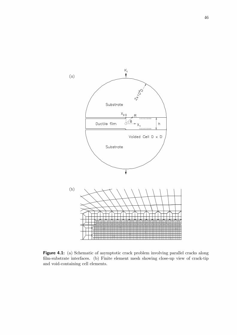
46
Figure 4.1: (a) Schematic of asymptotic crack problem involving parallel cracks alongfilm-substrate interfaces. (b) Finite element mesh showing close-up view of crack-tipand void-containing cell elements.
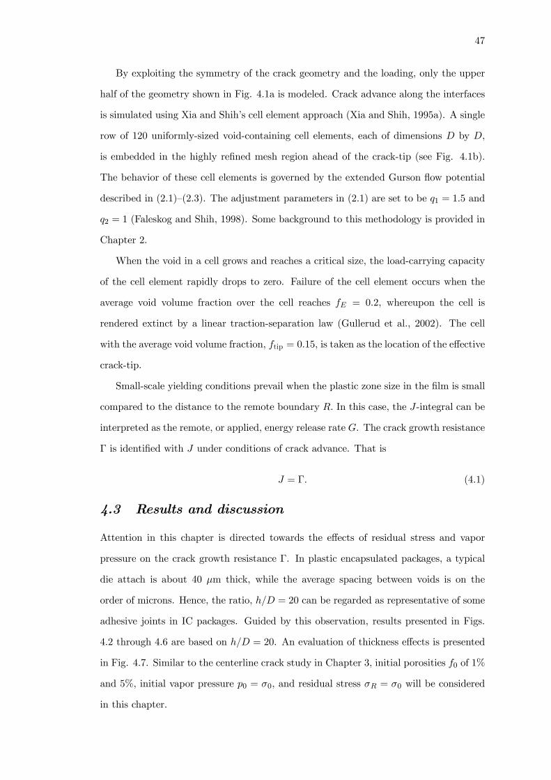
47
By exploiting the symmetry of the crack geometry and the loading, only the upper
half of the geometry shown in Fig. 4.1a is modeled. Crack advance along the interfaces
is simulated using Xia and Shih’s cell element approach (Xia and Shih, 1995a). A single
row of 120 uniformly-sized void-containing cell elements, each of dimensions D by D,
is embedded in the highly refined mesh region ahead of the crack-tip (see Fig. 4.1b).
The behavior of these cell elements is governed by the extended Gurson flow potential
described in (2.1)—(2.3). The adjustment parameters in (2.1) are set to be q1 = 1.5 and
q2 = 1 (Faleskog and Shih, 1998). Some background to this methodology is provided in
Chapter 2.
When the void in a cell grows and reaches a critical size, the load-carrying capacity
of the cell element rapidly drops to zero. Failure of the cell element occurs when the
average void volume fraction over the cell reaches fE = 0.2, whereupon the cell is
rendered extinct by a linear traction-separation law (Gullerud et al., 2002). The cell
with the average void volume fraction, ftip = 0.15, is taken as the location of the effective
crack-tip.
Small-scale yielding conditions prevail when the plastic zone size in the film is small
compared to the distance to the remote boundary R. In this case, the J-integral can be
interpreted as the remote, or applied, energy release rate G. The crack growth resistance
Γ is identified with J under conditions of crack advance. That is
J = Γ. (4.1)
4.3 Results and discussion
Attention in this chapter is directed towards the effects of residual stress and vapor
pressure on the crack growth resistance Γ. In plastic encapsulated packages, a typical
die attach is about 40 μm thick, while the average spacing between voids is on the
order of microns. Hence, the ratio, h/D = 20 can be regarded as representative of some
adhesive joints in IC packages. Guided by this observation, results presented in Figs.
4.2 through 4.6 are based on h/D = 20. An evaluation of thickness effects is presented
in Fig. 4.7. Similar to the centerline crack study in Chapter 3, initial porosities f0 of 1%
and 5%, initial vapor pressure p0 = σ0, and residual stress σR = σ0 will be considered
in this chapter.

48
For most of the computations, the properties of the elastic-plastic film are specified
by the parameters σ0/E = 0.01, N = 0.1 and ν = 0.4. The level of elastic modulus
mismatch between the film and the substrate considered is Es/E = 5, with νs = 0.3.
The thermal cooling problem is dealt with first to ascertain the effects of film-substrate
coefficient of thermal expansion (CTE) mismatch on parallel debonding. This is followed
by a more systematic study of residual stress and vapor pressure effects on interface
toughness.
4.3.1 Film-substrate CTE mismatch
To gain some understanding of CTE mismatch effects during the cool down process,
vanishing displacements are prescribed at the remote boundary to set KI = 0 in Eq.
(3.5), i.e. the substrates are rigidly constrained. A temperature change, ∆T = T − T0,
will induce stresses in both the film and substrate which can be calculated from the
objective Cauchy stress rate
∇σ = L :(d− dp − dth) (4.2)
where L is an isotropic fourth-order elasticity tensor, d is the total strain rate, dp the
plastic strain rate (for the elastic substrate dp = 0), and dth = αT1 is the thermal
strain rate, with α denoting the CTE (of the film or substrate). In the context to follow,
the CTE of the film and substrate are denoted by α and αs respectively. At the reflow
temperature, T0 = 220◦C, both film and substrates are assumed to be stress free.
Figure 4.2a shows the temperature drop ∆T vs. crack extension ∆a/D for three
levels of film-substrate CTE mismatch, α/αs = 10, 30, and 60 (αs for the substrate
is 2.8 × 10⁻⁶/◦C, representative of silicon). This range of α/αs encompasses adhesivejoints found in flip-chip solder die and IC packaging. Observe that crack growth at the
interface is negligible when the temperature drop is less than about 50◦C from the solder
reflow temperature. Further cooling results in rapid crack propagation. Qualitatively,
temperature change induces near uniform stresses along the film-substrate interfaces.
A threshold temperature is required for interfacial void growth to undergo cavitation
instability, resulting in rapid delamination. When α/αs is large, the temperature drop
associated with interface cracking is smaller. In contrast, a low α/αs requires a higher
threshold temperature for failure.
49
Figure 4.2: Crack growth induced by cool down process for three levels of CTE mis-match. (a) Temperature drop vs. crack growth along film-substrate interface of thejoint; (b) crack growth resistance of the joint.
Figure 4.2b shows the computed crack growth resistance curves, Γ/ (σ0D) vs. ∆a/D,
for the three cases α/αs = 10, 30, and 60. Here Γ is given by the J-integral computed
on a number of contours enclosing the damage process zone (ranging from 6 to 1000h
from the crack-tip) using the domain integral method (Moran and Shih, 1987). The
computed J-integrals are independent of the domain size. The R-curves display these
trends — initial crack growth is characterized by rapid increase in Γ. The rate of increase
of Γ slows down significantly for crack growth beyond about 10D. One can see the
three-fold drop in the crack growth resistance when α/αs increases from 10 to 60.
It should be noted that the boundary conditions imposed in the above model problem
are considerably more severe than those that exist during the solder reflow process.
Moreover, the yield strength of the polymer is a function of the temperature. This

50
notwithstanding, the R-curves in Fig. 4.2b provide (i) some quantitative indication
of how the level of film-substrate CTE mismatch affects the toughness of the joint
and (ii) toughness values for comparison with those obtained by isothermal analysis
incorporating initial residual stress σR/σ0 induced by CTE mismatch. This is addressed
in the next few sections.
4.3.2 Residual stress in film
In this and subsequent sections, the stresses at the interface and the resulting crack
growth are brought about by gradually increasing the remoteKI displacement field given
in Eq. (3.5). As a check that small scale yielding conditions are met, the J-integral is
computed for several outer annular spatial domains at every stage of the analysis. The
computed J-values and the prescribed K values were found to be consistent with (3.6).
The initial in-plane biaxial residual stress in the ductile film is prescribed by imposing
components of initial strain in the film. See Eqs. (3.3) and (3.4).
Figure 4.3a shows the effect of different levels of residual stress on crack growth at
the interface. An increase in residual tensile stress σR/σ0 lowers the rate of increase of Γ,
as well as reduces the steady-state toughness Γss. Following Tvergaard and Hutchinson
(1996), the toughness of the joint Γss is defined as the asymptotic value where Γ is
effectively independent of ∆a. It can be seen that Γss is reached after growth ranging
from about 10D to about 15D. A plot of Γss/(σ0D) as a function of σR/σ0 is provided
in Fig. 4.3b. Residual compressive stress increases the fracture toughness slightly, while
a residual tensile stress of σR/σ0 = 0.4 can lower the fracture toughness by about 40%.
Beyond about σR/σ0 = 0.4, further reduction in fraction toughness is minimal. Residual
stress of these levels are not uncommon in technological applications. Qualitatively
a residual tensile stress, acting in conjunction with remotely applied mode I loading,
increases the hydrostatic stresses ahead of the crack which in turn accelerates void
growth and coalescence. The rising R-curves in the transient crack growth plots in Fig.
4.3a are associated with plastic dissipation in the ductile film (observe advance of plastic
zone). A study of the evolution of plastic zones in the film can give further insights into
the fracture toughness of the film-substrate interface.
Figure 4.3c displays the plastic zones for four residual stress levels, σR/σ0 = 0.0,
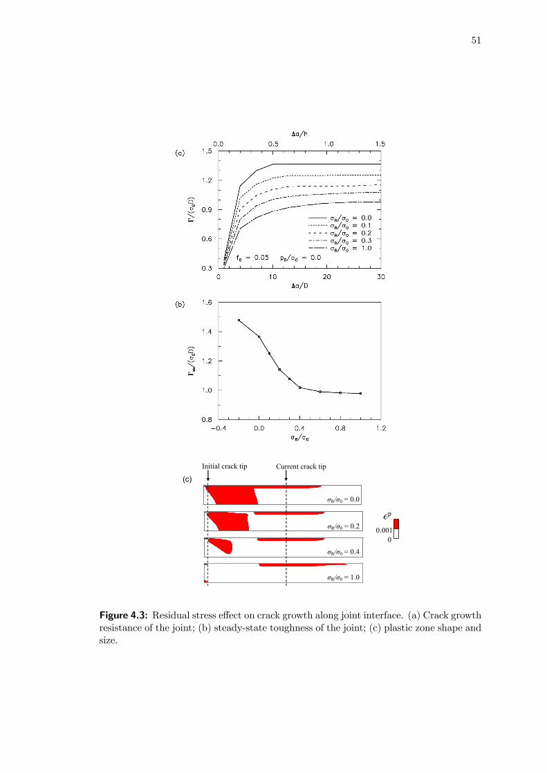
51
0 0.001
Initial crack tip Current crack tip
(c)
σR/σ0 = 0.0
σR/σ0 = 0.2
σR/σ0 = 0.4
σR/σ0 = 1.0
Figure 4.3: Residual stress effect on crack growth along joint interface. (a) Crack growthresistance of the joint; (b) steady-state toughness of the joint; (c) plastic zone shape andsize.

52
0.2, 0.4 and 1.0. In these plots, the crack has grown a distance of 2h. The plastic zones
are operationally defined by p > 0.001, where p is the accumulated plastic strain. The
actual plasticity that develops in the film occupies a much larger region since onset
of plasticity occurs when p > 0. Observe two features. Initially, the plastic zone,
p > 0.001, spreads out across the full width of the film. As the cracks grow, the plastic
zone changes its shape — the new growth of the plastic zone is confined to the vicinity
of the interface. It may also be noted that the overall size of the plastic zone decreases
with increase of σR/σ0. This behavior is consistent with the results shown in Fig. 4.3b.
4.3.3 Vapor pressure at film-substrate interface
Pores and cavities form at filler particle-polymer matrix interfaces, at polymer film-
substrate interfaces as well as in molding compounds of IC packages. In a humid en-
vironment, moisture diffuses to these voids. During reflow soldering, surface mount
plastic encapsulated devices are exposed to temperatures between 210 to 260◦C. At
these temperatures, the condensed moisture vaporizes. The rapidly expanding water
vapor exerts internal pressures on the voids that could reach 3-6MPa. Such stress levels
are comparable to the yield strengths of epoxy molding compounds and epoxy adhesives
whose glass transition temperatures Tg range between 150 to 300◦C.
Figure 4.4a shows how crack growth resistance is affected by the presence of vapor
pressure at the interface. Vapor pressure reduces both the rate of increase of Γ as well as
the steady-state toughness Γss. High vapor pressure, p0/σ0 = 1.5, can reduce fracture
toughness by a factor of 2, all other parameters remaining the same. The combined
effect of vapor pressure and residual tensile stress on crack growth resistance is shown
in Fig. 4.4b.
Figure 4.4c displays plastic zone sizes corresponding to three cases (p0/σ0 = 0.5, 1.0
and 1.5) considered in Fig. 4.4a. The cracks have grown by 2h and one can see that the
plastic zones associated with high vapor pressure (p0/σ0 > 1) are effectively confined
to the vicinity of the interface. Figure 4.4d displays plastic zones that develop under
the combined action of vapor pressure and residual tensile stress (three cases considered
in Fig. 4.4b). The plastic zones are narrow and are confined to the vicinity of the
interface. These results suggest the joint toughness of the interface to be significantly

53
0 0.001
Current crack tip Initial crack tip
p0/σ0 = 0.5
p0/σ0 = 1.0
p0/σ0 = 1.5
Current crack tip Initial crack tip
p0/σ0 = 0.5
p0/σ0 = 1.0
p0/σ0 = 1.5
(c)
(d)
Figure 4.4: Vapor pressure effect at film-substrate interface on crack growth resistanceof the joint. (a) σR/σ0 = 0; (b) σR/σ0 = 1; (c) and (d) plastic zones corresponding tothree cases considered in (a) and (b) respectively.
reduced under the combined action of thermal stress and vapor pressure.
4.3.4 Porosity of film-substrate interface
As noted earlier, estimates of porosity f0 based on moisture analyses range from 1% to
5% (Galloway and Miles, 1997). Figure 4.5a shows the interface R-curves for several
values of f0, with σR/σ0 = 1; Fig. 4.5b includes vapor pressure effects p0/σ0 = 1. One
can see the strong effect of porosity on crack growth resistance. For example, Γss for
f0 = 0.05 is about 50% lower than that for f0 = 0.005. Moreover high vapor pressure,
comparable to the material’s yield stress, can reduce Γss by as much as 30% (compare
Figs. 4.5a and 4.5b).
4.3.5 Strain hardening of film
Zhang et al. (2002) showed the interfacial fracture energy can be a strong function
of both the initial porosity and the strain hardening exponent. Figure 4.6a shows the
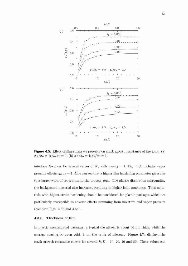
54
Figure 4.5: Effect of film-substrate porosity on crack growth resistance of the joint. (a)σR/σ0 = 1; p0/σ0 = 0; (b) σR/σ0 = 1; p0/σ0 = 1.
interface R-curves for several values of N , with σR/σ0 = 1; Fig. 4.6b includes vapor
pressure effects p0/σ0 = 1. One can see that a higher film hardening parameter gives rise
to a larger work of separation in the process zone. The plastic dissipation surrounding
the background material also increases, resulting in higher joint toughness. Thus mate-
rials with higher strain hardening should be considered for plastic packages which are
particularly susceptible to adverse effects stemming from moisture and vapor pressure
(compare Figs. 4.6b and 4.6a).
4.3.6 Thickness of film
In plastic encapsulated packages, a typical die attach is about 40 μm thick, while the
average spacing between voids is on the order of microns. Figure 4.7a displays the
crack growth resistance curves for several h/D — 10, 20, 40 and 80. These values can

55
Figure 4.6: Effect of hardening of film on crack growth resistance of the joint. (a)σR/σ0 = 1; p0/σ0 = 0; (b) σR/σ0 = 1; p0/σ0 = 1.
be regarded as representative of adhesive joints in packaging material. Results are
generated using a modified mesh of Fig. 4.1b, where the number of elements in the
film is correspondingly altered with the film thickness. In the absence of vapor pressure
and residual stress, the effect of h/D on joint toughness is substantial. An increase
in h/D from 10 to 20 raises the Γss by about 50%. The limit of fracture toughness
enhancement with film thickness appears to be reached when h/D = 80. By contrast,
under high residual stress σR/σ0 = 1, increasing h/D from 10 to 20 raises the Γss by
about 30% (Fig. 4.7b). Smaller enhancement in joint toughness for h/D of 40 and 80
can be seen. A similar behavior is observed under high vapor pressure p0/σ0 = 1 (Fig.
4.7c). The behavior under combined residual stress and vapor pressure follows closely
to that in Fig. 4.7c. In other words, when both residual stress and vapor pressure are

56
Figure 4.7: Effect of thickness of film on crack growth resistance of the joint. (a)σR/σ0 = 0, p0/σ0 = 0; (b) σR/σ0 = 1, p0/σ0 = 0; (c) σR/σ0 = 1, p0/σ0 = 1.

57
present, vapor pressure effects are dominant. These observations could be explained by
the plastic zone patterns shown in Figs. 4.3c, 4.4c, and 4.4d.
In the absence of vapor pressure and residual stress, initial plastic zone spreads out
across the full width of the film (Fig. 4.3c). An increase in h/D would permit greater
plastic dissipation in the ductile film, thereby enhancing the joint toughness. When the
extent of the plastic zone is smaller than the thickness of the film, the effect of h/D will
diminish. With pre-existing residual stress or vapor pressure in the film, the plastic zone
is confined to the vicinity of the interface (Figs. 4.3c, 4.4c and 4.4d). As such, increase
in the film thickness will produce smaller enhancement on the joint toughness.
4.4 Concluding remarks
Plastic encapsulated microcircuits are susceptible to interface cracking during solder
reflow that could possibly lead to popcorn cracking. The analysis of crack growth
during the cool down process (following solder reflow) provides some estimates of the
reduction in joint toughness related to film-substrate CTE mismatch. These estimated
joint toughness values are comparable to those obtained from isothermal analyses where
the CTE mismatch is treated by introducing an initial residual stress. Crack growth
computations show that residual stress in the film combined with vapor pressure enhance
brittle-like cracking characteristics, bringing about severe reduction in toughness of the
joint. The reduction in joint toughness can be compounded when the porosity of the
material near the interface is high.
Attention in this chapter is directed at residual stress and vapor pressure effects
on cracking and toughness of joints formed by a ductile polymeric film and its elastic
substrates. Residual stresses are induced by the CTE mismatch between the film and
substrates it joins. Tensile residual stress reduces joint toughness. The effects of rapid
moisture vaporization are manifested in several ways. High vapor pressure within cav-
ities accelerates void growth and coalescence. As a result, the toughness of the joint is
reduced significantly. When both residual stress and vapor pressure are present, vapor
pressure effects are dominant. It has also been observed that vapor pressure exerts trac-
tions on crack faces contributing to an additional driving force as well as mode mixity

58
shift (from shear-dominated to tension-dominated) both of which are increasing func-
tions of the crack size. The combination of accelerated void growth, increased driving
force and tension-dominant mode mixity enhances the prospects of brittle-like debond-
ing. A discussion of these aspects can be found in Liu et al. (2003) and Cheng and Guo
(2003).

59
CHAPTER 5
INTERFACIAL TOUGHNESS OF DUCTILE
ADHESIVE JOINTS UNDER MIXED MODE LOADING
Research scope
Mixed mode loading comprising of a strong mode II component represents the actualloading state in multilayers and IC devices, since residual stress induces a predomi-nantly mode II loading at the interfaces. This chapter examines the effects of vaporpressure and residual stress on the mixed mode interfacial toughness of the adhesivejoint.
Main findings
The adverse effects of vapor pressure are greatest under a strong mode II loading, andcan cause a several-fold drop in joint toughness. These interface toughness levels arecomparable with available experimental data.
Extracts from this chapter can be found in Journal Paper [3] and Conference Paper[1].
5.1 Introduction
Interfaces are among the most critical features of microelectronic packages. The chem-
istry aspects of moisture-assisted crack growth at epoxy-glass interfaces have been stud-
ied by Ritter et al. (1998). They observed that water molecules are preferentially
absorbed on glass surface, displacing epoxy molecules and breaking interface secondary
bonds. Moisture effects can cause significant reductions in epoxy-glass interface tough-
ness. Gurumurthy et al. (2001) examined the water-assisted sub-critical crack growth
along a polyimide passivation/epoxy underfill interface. They measured the sub-critical
crack growth velocity at various relative humidities and temperatures as a function of
the crack driving force, and showed that the presence of moisture produced a marked de-
crease (by up to a factor of 12) in the energy release rate for crack growth at measurable
velocities.
Chai (2003) and Madhusudhana and Narasimhan (2002) conducted experimental
and numerical investigations on the mixed mode toughness of an adhesive bond. They

60
observed the mode I fracture toughness to be weakly dependent on the film thickness,
while the toughness increases as the mode II component increases. An earlier experi-
mental study by Chai (1988) investigated the relationship between the adhesive bond
thickness and the shear fracture work under mode II and III loadings. Other studies
characterizing the voiding-induced crack growth in polymers were conducted by Tijssens
et al. (2000b) and Pijnenburg et al. (1999). More recently, Strohband and Dauskardt
(2003) showed that residual thin-film stresses under varying mode mixities could alter
plasticity in the ductile layer, and hence influence the macroscopic fracture energy.
This chapter addresses the interface cracking of an adhesive joint, with emphasis
on the effects of vapor pressure and residual stress on void growth. In IC packages,
residual stress arising from the mismatch in thermal expansion coefficients induces a
predominantly mode II component on the adhesive-substrate interfaces. Void growth
and coalescence occur under high vapor pressure superposed on this background stress.
In Chapter 4, void coalescence (and hence crack growth) was assumed to occur when the
porosity of a Gurson cell reaches a critical level. An improved void coalescence model
introduced by Tvergaard and Needleman (1984) could more realistically account for the
loss of macroscopic stress in a cell at large porosity levels. This model is adopted in this
chapter to accurately predict final package failure.
5.2 Modeling aspects
Figure 5.1 displays a crack along one of the interfaces of an adhesive film of thickness
h. The film is sandwiched between two substrates. The two substrates are taken to be
elastic with Young’s modulus, Es, and Poisson’s ratio, νs. The elastic properties of the
film are specified by E and ν.
5.2.1 Material model
Around the glass transition temperature, Tg, certain polymers including epoxies be-
have like elastic-plastic solids exhibiting extensive ductility and hardening. This study
assumes that the matrix material of the adhesive film can be described as an elastic-
plastic, power-law hardening material. The plastic response of the film is characterized
by a J2 flow theory. Above Tg, large viscoelastic or viscoplastic deformations are possi-
ble (Gibson and Ashby, 1997, Ch. 3). A related study characterizing the steady crack

61
Figure 5.1: An adhesive (with an interface crack) joining two elastic substrates.
growth in an elastic-viscoplastic medium has been carried out by Xia and Cheng (1996).
Interface delamination is modeled using Xia and Shih’s (1995a) cell element ap-
proach. A strip of void-containing cell elements is embedded at the film-substrate in-
terface ahead of the crack-tip. The behavior of these cell elements is described by the
extended Gurson flow potential in (2.1)1, with micromechanics parameters q1 and q2
taken to be 1.25 and 1 respectively (Faleskog et al., 1998).
Final failure of a porous ductile solid occurs by void coalescence. The Gurson con-
stitutive model (2.1) does not predict a realistic loss of macroscopic stress in a cell at
large void fractions. Tvergaard and Needleman (1984) introduced an accelerated value
of the current void volume fraction f , denoted by f∗, to overcome this deficiency. The
present work adopts
f∗ =
⎧⎪⎪⎪⎪⎨⎪⎪⎪⎪⎩f, f ≤ fC
fC +f∗U − fCfF − fC
(f − fC), fC < f ≤ fF
f∗U , f > fF
(5.1)
for use, where fC is the critical void volume fraction for coalescence, and fF is the void
1Note that the symbol f in (2.1) is to be replaced by f∗.

62
volume fraction at final rupture so that f∗(fF ) = f∗U = 1/q1. To model the complete
loss of material stress carrying capacity at a realistic void volume fraction, values of
fC = 0.15 and fF = 0.25 are used during which void coalescence takes place (Tvergaard
and Needleman, 1984).
The vapor pressure p in (2.1) is a new internal variable given by
p
p0=
⎧⎪⎪⎪⎪⎪⎪⎪⎨⎪⎪⎪⎪⎪⎪⎪⎩
T
T0
f0f
1− f
1− f0e−3α∆T , f ≤ fC
T
T0
f0fC
1− fC1− f0
e−3α∆T fF − f
fF − fC, fC < f ≤ fF
0, f > fF
(5.2)
which relates the current state (p, f, T ) to the initial state (p0, f0, T0). In the above, α
is the coefficient of thermal expansion (CTE), and ∆T is the temperature rise relative
to the reference temperature T0. For the present isothermal analysis, ∆T = 0. When
f = fF , the yield surface (2.1) shrinks to a point.
In the respective piecewise description of f∗ and p, the third branch for f > fF is
defined to predict an identically vanishing stress state even if f ≥ fF . In the numerical
implementation of this material model, a cubic transition around fC is inserted between
the first two branches of functions in (5.1) and (5.2) respectively. Such a spline smooth-
ing is necessary to improve convergence of the global Newton iterations, especially when
using a backward Euler integrator (Gullerud et al., 2002).
The void growth rate f is governed by the plastic volumetric strain rate in (2.3) with
nucleation neglected. The extended Gurson model (2.1) together with (2.3), (5.1) and
(5.2) describe the full process of void growth, coalescence and failure.
5.2.2 Small-scale yielding
Figure 5.2a displays the finite element mesh of the crack geometry in Fig. 5.1; Figure
5.2b displays the inner region of the finite element mesh near the crack-tip — a single
row of void-containing cell elements is embedded in the highly refined mesh region in
front of the initial crack-tip. Each cell element, of dimensions D by D, has a void of
initial volume fraction f0 associated with initial vapor pressure p0. The example mesh for
h/D = 40 contains 7,858 linear elements including 120 cell elements. The computations
are carried out under plane strain conditions using the finite element program WARP3D
(Gullerud et al., 2002).
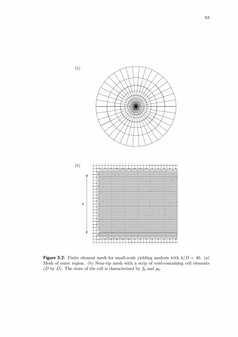
63
Figure 5.2: Finite element mesh for small-scale yielding analysis with h/D = 40. (a)Mesh of outer region. (b) Near-tip mesh with a strip of void-containing cell elements(D by D). The state of the cell is characterized by f0 and p0.

64
The applied remote load,K, is characterized by the mode mixity ψ = tan−1(KII/KI)
and the magnitude of stress intensity |K| =qK2
I +K2II . Here KI and KII are the
mode I and II stress intensity factors. Unless otherwise stated, the film thickness h is
taken to be 40D. Along the remote circular boundary, the elastic asymptotic in-plane
displacement fields
u1 (R, θ) = |K| 1 + νsEs
rR
2π
∙2(1− 2νs) cos θ
2cosψ + 4(1− νs) sin
θ
2sinψ
+(cosθ
2sinψ + sin
θ
2cosψ) sin θ
¸u2 (R, θ) = |K| 1 + νs
Es
rR
2π
∙4(1− νs) sin
θ
2cosψ − 2(1− 2νs) cos θ
2sinψ
−(cos θ2cosψ − sin θ
2sinψ) sin θ
¸(5.3)
are prescribed. Here R2 = X21 +X2
2 and θ = tan−1 (X2/X1) for points on the remote
boundary. Edge loads at the ends of the ductile adhesive are neglected since the error
introduced is small (Tvergaard and Hutchinson, 1996).
For the crack geometry in this study, Irwin’s relation between the stress intensity
factor K and the energy release rate G is given by (3.6). Small-scale yielding conditions
prevail when the plastic zone size in the film is small compared to the distance to the
remote boundary. Similar to studies conducted in Chapters 3 and 4, the J-integral
can be interpreted as the remote, or applied, energy release rate G. The crack growth
resistance Γ is identified with J under conditions of crack advance. At various stages
of loading, the value of the J-integral is calculated on a number of contours around the
crack using the domain integral method (Moran and Shih, 1987). The domain integral
value is found to be in good agreement with the value given by (3.6). This consistency
check assures that small-scale yielding conditions are satisfied.
Under small-scale yielding conditions, the applied energy release rate G can be ap-
proximately equated with the near-tip energy release rate Gtip in (A.1) in Appendix A.
From this relationship, the magnitude of K can be identified with that of the near-tip
complex stress intensity factor Ktip. Vapor pressure effects are manifested in two differ-
ent ways: (i) high vapor pressure within cavities accelerates the process of void growth
and coalescence; (ii) vapor pressure exerts tractions on crack faces and on defects at
interfaces. The former is modeled as an internal void pressure p in (2.1), while the latter
forms a component of Ktip. The applied K then represents the effective crack driving

65
force from the contributions of both the background stress and the traction-vapor pres-
sure on the crack faces. Details of the crack driving force can be found in Appendix
A.
5.3 Crack growth procedure and validation5.3.1 Parametric dependence
From dimensional considerations, the steady-state fracture resistance Γss depends on
the following dimensionless geometric-material parameters:
Γssσ0D
= F
µh
D;σ0E,Es
E,N, ν, νs; f0,
p0σ0;σRσ0;ψ
¶. (5.4)
The characteristic length, D, enters explicitly as a scaling length. Interpretations of D
and f0, in terms of the spacing between void nucleating second-phase particles and the
size of these particles in the context of metal fracture, can be found in Xia and Shih
(1995a) and Faleskog et al. (1998). In the present work, D is taken as a characteristic
length of the void growth-coalescence mechanism at the film-substrate interface. A cell
element extinction procedure of WARP3D is invoked in the computation to reduce plau-
sible divergence problems before steady-state toughness is reached. When the average
void volume fraction over the cell reaches fE (a value close to fF with small remaining
stresses), the cell is rendered extinct by a linear traction-separation law (Gullerud et al.,
2002). Computations in this study will be based on fE = 0.2. The cell with the average
void volume fraction, ftip = 0.1, is taken as the effective location of the crack-tip (Xia
and Shih, 1995a).
5.3.2 Model validation
To gain some understanding on the mixed mode toughness of the adhesive film, the
transient crack growth resistance curves for f0 = 0.05 are examined in Fig. 5.3a. The
polymeric adhesive is specified by the parameters σ0/E = 0.01, ν = 0.4 and N = 0.1,
while the level of elastic modulus mismatch between the film and substrate is Es/E = 10,
with νs = 0.3. Three mode mixity levels are considered: ψ = 0◦, 20◦ and 40◦. The crack
growth resistance Γ is the sum of the work in the fracture process zone Γ0, and the
plastic dissipation in the surrounding ductile material Γp. The resistance curves show a
common trend: A rapid rise in Γ characterizes the initial crack propagation, while the

66
Figure 5.3: (a) Crack growth resistance plots for f0 = 0.05, N = 0.1, under ψ = 0◦, 20◦
and 40◦. The solid curves are for p0 = 0 and the dotted curves for p0 = σ0. (b) Deformedmesh with scaling factor of 3 under ψ = 0◦, 20◦ and 40◦ for p0 = 0 at ∆a/D = 13.5(crack advance by 14 elements).

67
steady-state fracture toughness Γss is reached for nearly all curves after a transient crack
growth of ∆a/D ≤ 13. These trends are clearly identified in experimental investigationson the interfacial fracture behavior of a flip-chip package by Wang et al. (1998). One
can see that a higher ψ gives rise to a larger work of separation in the process zone.
The plastic dissipation surrounding the background material also increases, resulting in
higher joint toughness.
The deformed mesh (with scaling factor of 3) for ψ = 0◦, 20◦ and 40◦ at∆a/D = 13.5
(crack advance by 14 elements) is shown in Fig. 5.3b for p0 = 0. The arrows denote the
initial crack-tip locations. Observe the more dominant shear as ψ increases. This shear
loading contributes to the formation of a larger plastic zone, hence resulting in higher
Γss. The extensive plastic deformation zone that develops under shear loading has been
reported by Chiang and Chai (1994).
In the presence of vapor pressure, the joint toughness is significantly lowered (dotted
curves in Fig. 5.3a). In plastic encapsulated packages, a typical die attach is about 40 μm
thick (h = 40D = 40 μm; D = 1 μm). Assuming the adhesive under reflow conditions
has a yield strength of σ0 = 5 MPa, i.e. σ0D = 5 Nm−1, an increase in p0 from 0 to
σ0 under ψ = 0◦ reduces the joint toughness Γss from 3 to 2.5 Jm−2. Comparatively,
under ψ = 20◦, Γss is reduced from 3.7 to 2.7 Jm−2. With a higher mode mixity level of
ψ = 40◦, the reduction in joint toughness is more severe (from Γss = 4.8 to 3.2 Jm−2).
The above Γss values are strongly dependent on σ0 and can be considered as upper
limits, since the adhesive yield strength at reflow temperatures varies from 2-5 MPa (as
listed in (3.1)). In Evans et al. (1999), the estimated fracture toughness for interfaces
between thin films and thick substrates ranges between 2-5 Jm−2. Gurumurthy et al.
(2001) conducted an experimental study on crack growth along an interface between
polyimide passivation and epoxy underfill. They observed a marked reduction in the
interfacial fracture toughness under moisture-assisted delamination. In certain cases,
the joint toughness was reduced to levels of around 2 Jm−2, which is comparable to that
predicted in this numerical study for p0 = σ0.

68
Figure 5.4: Interface toughness versus mode mixity for three levels of elastic modulusmismatches with f0 = 0.05, N = 0.1.
5.4 Steady-state toughness
In this section, attention is directed to the effects of p0/σ0, σR/σ0 and h/D on the
steady-state joint toughness Γss under mixed-mode loading.
The properties of the elastic-plastic film are specified by the parameters σ0/E = 0.01
with ν = 0.4. From the parametric study of the elastic moduli mismatch effects on the
steady-state mixed mode toughness of the interface in Fig. 5.4, the shielding effects of
elastic substrates are found to be negligible for Es/E < 100. At higher Es/E ratios,
the stiffer substrates offer larger shielding effects, causing significant joint toughness
enhancement across all mode mixity levels. This can be seen by comparing the plots
for Es/E = 10 and 100 with Es/E = 1000, for the p0 = 0 case. Similar joint toughness
enhancement is noted for p0 = σ0. Based on these findings, the level of elastic modulus
mismatch between the film and the substrate is taken to be Es/E = 10 with νs = 0.3.
These material parameters are representative of polymer-silicon joints in IC packages.
5.4.1 Vapor pressure effects
Figure 5.5a displays the steady-state mixed mode toughness for f0 = 0.05 with three
levels of vapor pressure: p0/σ0 = 0, 0.5 and 1. The plots for f0 = 0.01 are displayed in
Fig. 5.5b. The solid curves represent the plastic hardening parameter of N = 0.1 while
the dotted curves represent N = 0.2. The effects of mode mixity are examined first.
The fracture toughness is greatly enhanced as the mode II component of the applied

69
Figure 5.5: Interface toughness versus mode mixity for three levels of vapor pressurewith (a) f0 = 0.05; (b) f0 = 0.01. The solid line curves are for N = 0.1 and the dottedcurves for N = 0.2.
load increases. In the presence of vapor pressure, the increase in the interface fracture
toughness Γss with ψ for high porosity adhesives becomes relatively smaller (Fig. 5.5a).
For example for f0 = 0.05, N = 0.1 with p0 = 0, an increase in mode mixity level from
pure mode I loading (ψ = 0◦) to a mode II dominant loading (ψ = 60◦) increases Γss
by five-fold; the increment is about 1.6 times for p0 = σ0.
For both porosity levels, vapor pressure causes significant reduction in joint tough-
ness. It is noteworthy that the adverse effects of vapor pressure on interface integrity
of highly porous adhesives become more dominant as ψ increases. For example, at
mode mixity levels between 40◦ ≤ ψ ≤ 60◦, the interface fracture toughness Γss for
f0 = 0.05 with N = 0.1 suffers a two- to three-fold reduction for initial vapor pressure
p0 comparable to σ0. This range of mode mixity is representative of the likely state of in-
terface loading for PEMs, since residual stress resulting from the film-substrate thermal

70
Figure 5.6: Interface toughness versus mode mixity for three levels of residual stresswith N = 0.1, (a) f0 = 0.05; (b) f0 = 0.01. The solid line curves are for p0 = 0 and thedotted curves for p0 = σ0.
mismatch induces a predominantly mode II component.
A comparison between the plots for N = 0.1 and 0.2 show that higher strain harden-
ing gives rise to higher joint toughness. The fracture toughness of the joint is the sum of
two contributions: the work of separation in the process zone and the plastic dissipation
in the ductile adhesive. Both increase significantly with increasing hardening.
5.4.2 Residual stress and vapor pressure effects
Residual stress effects on the interface toughness of polymeric adhesives are taken up
here. The stress arising from thermal expansion mismatch between the adhesive and
the substrate is treated as an initial residual stress. High residual stresses, comparable
to the adhesive’s yield strength, are not uncommon in IC packages where adhesives are
deposited at elevated temperatures.

71
Results for a high porosity adhesive, f0 = 0.05, are first presented. Figure 5.6a
shows the steady-state mixed mode toughness with residual stress levels σR ranging
from −0.5σ0 to σ0. The solid curves representing p0 = 0 are first examined. Residual
compressive stress (σR = −0.5σ0) significantly increases the interface fracture toughnessΓss across the considered range of mode mixities. By contrast, increasing residual tensile
stress reduces the plastic dissipation in the adhesive thus lowering the fracture tough-
ness. Qualitatively a residual tensile stress, acting in conjunction with remotely applied
loading, increases the hydrostatic stresses ahead of the crack. This in turn accelerates
void growth and coalescence. The adverse effects of residual tensile stress are greatest
within the range of 30◦ ≤ ψ ≤ 50◦.The effects of several residual stress levels combined with initial void vapor pressure
of magnitude p0 = σ0 are next examined (dotted curves). Note the similar interfacial
toughness levels between the curves for σR = 0 and σR = σ0 within the range of mode
mixities considered. By contrast under mixed-mode loading with p0 = 0 (solid curves),
the contribution of residual tensile stress plays a significant role in reducing Γss.
Figure 5.6b displays the plots for a low porosity adhesive, f0 = 0.01 for both p0 = 0,
and p0 = σ0. Compared with Fig. 5.6a, the plots for f0 = 0.01 are associated with higher
fracture toughness across all levels of residual stress. In addition, when combined with
internal void vapor pressure (dotted curves in Fig. 5.6b), residual tensile stress still has
distinct influence on the fracture toughness particularly within the mode mixity range
of 20◦ ≤ ψ ≤ 50◦.Figure 5.7 displays the cross-plots of Γss/(σ0D) against σR/σ0 at ψ = 40◦ for vapor
pressure levels of p0/σ0 = 0, 0.5, 1, in Fig. 5.7a with f0 = 0.05 and in Fig. 5.7b with
f0 = 0.01. The solid line curves are for N = 0.1 and the dotted curves for N = 0.2. As
discussed earlier, interface loading of ψ = 40◦ is not uncommon in plastic packages. The
characteristics of these plots are in line with the observations made in connection with
Fig. 5.6. It can be seen that in the range 0.5σ0 ≤ σR ≤ σ0, residual stress effects on
joint toughness are not significantly different.

72
Figure 5.7: Interface toughness versus residual stress for three levels of vapor pressurefor ψ = 40◦, (a) f0 = 0.05; (b) f0 = 0.01. The solid line curves are for N = 0.1 and thedotted curves for N = 0.2.
Figure 5.8: Interface toughness versus mode mixity for three film thicknesses withf0 = 0.05, N = 0.1. The solid line curves are for p0 = 0 and the dotted curves forp0 = σ0.
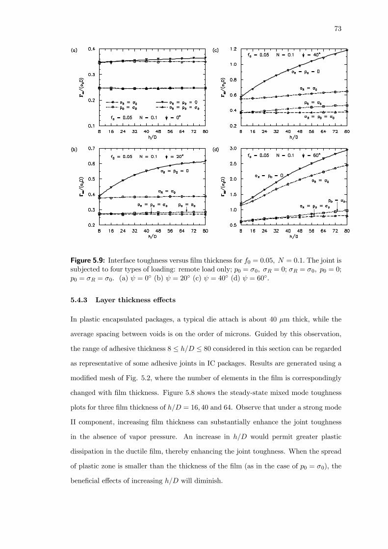
73
Figure 5.9: Interface toughness versus film thickness for f0 = 0.05, N = 0.1. The joint issubjected to four types of loading: remote load only; p0 = σ0, σR = 0; σR = σ0, p0 = 0;p0 = σR = σ0. (a) ψ = 0◦ (b) ψ = 20◦ (c) ψ = 40◦ (d) ψ = 60◦.
5.4.3 Layer thickness effects
In plastic encapsulated packages, a typical die attach is about 40 μm thick, while the
average spacing between voids is on the order of microns. Guided by this observation,
the range of adhesive thickness 8 ≤ h/D ≤ 80 considered in this section can be regardedas representative of some adhesive joints in IC packages. Results are generated using a
modified mesh of Fig. 5.2, where the number of elements in the film is correspondingly
changed with film thickness. Figure 5.8 shows the steady-state mixed mode toughness
plots for three film thickness of h/D = 16, 40 and 64. Observe that under a strong mode
II component, increasing film thickness can substantially enhance the joint toughness
in the absence of vapor pressure. An increase in h/D would permit greater plastic
dissipation in the ductile film, thereby enhancing the joint toughness. When the spread
of plastic zone is smaller than the thickness of the film (as in the case of p0 = σ0), the
beneficial effects of increasing h/D will diminish.

74
Figure 5.9 shows the plots for interface fracture toughness Γss/(σ0D) against adhe-
sive thickness h/D under four types of loading: (i) purely remote load; (ii) remote load
with vapor pressure (p0 = σ0); (iii) remote load with residual stress (σR = σ0); (iv)
remote load with vapor pressure and residual stress (p0 = σR = σ0). A total of ten
film thickness cases are computed with the discrete points in Fig. 5.9 representing the
numerical values.
For all four types of loading at ψ = 0◦ (Fig. 5.9a), no distinct fracture toughness
enhancement is observed with increasing film thickness. Under load type (i) at ψ =
20◦ (Fig. 5.9b), the fracture toughness is considerably enhanced with increasing h/D,
reaching a saturated peak at around h = 64D. At higher mode mixity levels of ψ =
40◦ and 60◦ (Figs. 5.9c and 5.9d), increasing h/D can raise the fracture toughness by
factors of 2 and 3 respectively (as compared to at ψ = 0◦). Under load type (iii), the
fracture toughness is only enhanced with increasing film thickness at high mode mixity
levels of ψ = 60◦. For load types (ii) and (iv), negligible enhancement in joint toughness
is observed with increasing film thickness across all mode mixity levels. Interestingly,
vapor pressure effects are most dominant under a strong mode II loading component
(Compare Figs. 5.9a and 5.9d). Observe that for large h/D, vapor pressure causes a
three- to four-fold drop in fracture toughness (Figs. 5.9c-d). Within the considered
range of mode mixity, the damaging effects of vapor pressure dominate over residual
stress (compare plots for p0 = σ0 and σR = σ0; p0 = σ0 and p0 = σR = σ0).
5.5 Concluding remarks
The computational study is focused on a ductile polymeric adhesive joining two elastic
substrates paying particular attention to the mixed mode interface fracture toughness.
The computational results show vapor pressure to have the most damaging effect on
the interface integrity; high levels of vapor pressure generated during reflow soldering
accelerate voiding activity leading to rapid crack propagation along the film-substrate
interface. This behavior is consistent with the catastrophic character of popcorn crack-
ing. The interface fracture toughness levels in this numerical study are comparable with
available experimental data (Evans et al., 1999; Gurumurthy et al., 2001).

75
In the presence of vapor pressure, negligible enhancement in joint toughness is ob-
served with increasing film thickness. Across all mode mixity levels, vapor pressure
effects dominate over residual stress. The adverse effects of vapor pressure are greatest
in highly porous adhesives subjected to a strong mode II component — these high levels
of vapor pressure can cause a several-fold drop in the joint toughness. The latter de-
notes the likely state of loading in IC packages since residual stress, resulting from the
film-substrate thermal mismatch, induces a predominantly mode II component.
In the present work, the vapor pressure effect on void growth and coalescence is
treated within the assumption of (5.2). This assumption can be conservative. In extreme
situations, where additional moisture vaporizes during void growth, a constant level of
high vapor pressure can be sustained for a considerable amount of void growth. Under
this scenario, the adverse effects of vapor pressure on the fracture toughness of the
joint can be significantly greater than those shown in this chapter. This subject will be
addressed in Chapters 6 and 7.

76
CHAPTER 6
PRESSURE-SENSITIVITY AND PLASTIC
DILATANCY EFFECTS ON VOID GROWTH AND
INTERACTION
Research scope
Compared to metals, the effects of primary and secondary voids on the mechanicalresponse of polymers are not as well understood. This chapter focuses on the role ofpressure sensitivity and micro-void growth in a unit-cell subjected to physical stressstates similar to highly stressed regions ahead of a crack. Effects of plastic dilatancyand void shape on the stress-carrying capacity of the cell are also considered.
Main findings
Increasing pressure-sensitivity severely reduces the material’s stress-carrying capacity,while multiple void interactions are responsible for the sharp post-peak stress drop,triggering rapid failure. In contrast, plastic dilatancy has some effect in raising thepost-peak stress levels, resulting in a larger work of separation.
Extracts from this chapter can be found in Journal Paper [5].
6.1 Introduction
The damage evolution and crack growth studies in Chapters 3—5 have assumed that
plastic response of the adhesive layers could be described by a von Mises yield criterion.
Experimental studies have shown that the deformation of polymers and certain metal
alloys differ from the von Mises material in two important aspects: (i) yield stress is de-
pendent on hydrostatic pressure; and (ii) plastic flow is non-volume preserving (Spitzig
and Richmond, 1984; Quinson et al., 1997). Focusing on crack-tip fields in unvoided con-
strained adhesive layers, Chowdhury and Narasimhan (2000a, b) showed that increasing
pressure-sensitivity could diminish the high hydrostatic stress levels previously observed
by Varias et al. (1991) for pressure-insensitive materials. Chang and Pan (1997) studied
the spherical void expansion in polymers and observed the cavitation stress to decrease
with increasing pressure-sensitivity. In the same spirit, Narasimhan (2004) analyzed
the spherical indentation response of plastics, and found the mean contact pressure to

77
increase with pressure-sensitivity. It is evident that pressure-sensitivity can change the
fracture response of a material.
Various modifier particles are added to polymers to improve their mechanical prop-
erties, including fracture toughness. In such polymer systems, the larger voids originate
from cavitated rubber blends or from the decohesion of filler particle/polymer matrix
interfaces, while another damage mechanism called crazing entails the formation of lo-
calized microporous zones (see Chapter 2.5). While the roles of primary voids and
secondary voids on the mechanical response and fracture of pressure-insensitive materi-
als (e.g. metals) are fairly well understood (Faleskog and Shih, 1997; Tvergaard, 1988;
Perrin and Leblond, 2000), there are comparatively fewer studies pertaining to the void
interaction effects in a pressure-sensitive matrix.
Another subject of interest is the effects of void shape on ductile fracture since voids
found in actual solids are rarely cylindrical or spherical in shape. Moreover, an initially
spherical void in the matrix material could evolve into a non-spherical shape under
deformation. To this end, Lee and Mear (1992, 1999) assessed the role of void shape
on the overall response of porous solids for a wide range of shape parameters. They
observed that ellipsoidal voids tend to coalesce more rapidly than circular voids, and
could influence the macroscopic fracture behavior of a von Mises solid. In a separate
study, Pardoen and Hutchinson (2000) showed the contribution of void shape effects to
the onset of coalescence could be reduced with increasing stress triaxiality.
This chapter examines the macroscopic response of porous pressure-sensitive dilatant
materials subjected to physical stress states similar to highly stressed regions ahead of
a crack. The pressure-sensitive yielding is described by a linear combination of the
mean stress and effective stress, while both associated and non-associated flow rules
are used. The study will be divided into two parts. In Part I, the coupled effect of
pressure-sensitivity and void shape is examined using an axisymmetric unit-cell model
containing a single void. The contribution of these parameters to the thermal- and
moisture-induced voiding phenomenon in IC packages is also discussed. Part II focuses
on the interaction between a single large void and a population of discrete microvoids
in a pressure-sensitive plane strain cell model.

78
Figure 6.1: A unit cell in an axisymmetric state, with geometric parameters and sym-metry lines.
6.2 Material model
Under isothermal conditions and small elastic strains, the material model is based on an
additive decomposition of the deformation rate d into an elastic part de and a plastic
part dp:
d = de + dp. (6.1)
The elastic part of the deformation rate is given by
de =1 + ν
E
5σ − ν
Etr(
5σ)I (6.2)
where E is the Young’s modulus, ν the Poisson’s ratio,5σ the objective co-rotational
Cauchy stress rate and I the identity tensor.
Experimental evidence shows that the plastic behavior of polymeric materials differ
considerably from the von Mises material (Quinson et al., 1997). Such behavior can
be explained by assuming a yield criterion based on a linear combination of the mean
stress and effective stress (Chiang and Chai, 1994; Jeong et al., 1994). Here, the pressure-
sensitive yielding under both associated and non-associated flow rules is described by
Eqs. (2.4) — (2.9) in Chapter 2. This pressure-dependent model is included in the
material library in ABAQUS Version 6.3.1 (2002).

79
6.3 Numerical modeling
This section describes the numerical procedure for the single void cell study. Numerical
details for the multiple size-scale void interaction study are presented in Section 6.5.
From statistical averaging, the voids are assumed to be uniformly dispersed in the matrix
material. The microstructure can then be described using an array of unit-cells, each
containing a single void. Figure 6.1 shows the initial cell geometry used. The unit-
cell is subjected to axisymmetric deformation, and a cylindrical coordinate system with
orthonormal frame {eρ,eφ,ez} is adopted there. The outer boundary of the cell has aninitial radius R. The void is initially ellipsoidal with radial and axial semi-axes a and
b. The initial void geometry is then specified by the void aspect ratio a/b and the void
volume fraction f0 = a2b/R3. The void is oblate when a > b, and prolate when a < b.
6.3.1 The axisymmetric cell
At finite strain, the micro deformation gradient F and the first Piola-Kirchhoff stress P
constitute a primary work-conjugate pair. Denoting the corresponding macro-variables
by F and P, the macro Cauchy stress Σ is then defined by
Σ = J−1P · FT (6.3)
where J = det F. This definition is equivalent to the volume average of the micro Cauchy
stress σ over the current deformed configuration of a macro-element. According to Hill
(1972), the macro-variables are governed by surface data of the representative volume
element. With respect to the reference configuration of volume V bounded by surface
S, the unsymmetric tensor P of the nominal stress takes the form
P = V −1ZSt⊗X dS (6.4)
where, for the axisymmetric cell shown in Fig. 6.1, X = ρeρ + zez denotes the initial
position of a typical material point on the outer surface (kXk = R) and t = tρeρ + tzez
the surface traction.
On the outer surface of the axisymmetric cell, the homogeneous deformation gradient
F = λρ (eρ ⊗ eρ + eφ ⊗ eφ) + λzez ⊗ ez (6.5)
is applied, where λρ and λz are the principal stretches in the radial and axial directions,
respectively. Equation (6.5) specifies the macroscopic principal strains (Eρ, Ez) and one

80
effective strain measure Ee:
Eρ = lnλρ, Ez = lnλz, Ee =23 |Ez −Eρ| . (6.6)
The surface traction vector t in (6.4) can be expressed in terms of the microscopic Cauchy
stress σ as t = P ·N = Jσ ·F−T·N, where N is the unit normal vector to the outer
surface in the reference configuration. For the unit-cell in Fig. 6.1,N = ez cos θ+eρ sin θ.
With the aid of (6.5), one can compute the deformed surface normal as
JF−T·N = JF−T·N =λ2ρ cos θ ez + λρλz sin θ eρ. (6.7)
It therefore follows that
tρ = σρρλρλz sin θ + σρzλ2ρ cos θ, tz = σzρλρλz sin θ + σzzλ
2ρ cos θ, (6.8)
where σij are the local Cauchy stress components on the surface. Substituting (6.4) and
(6.5) into (6.3) and using (6.8) yield
Σ = Σρ (eρ ⊗ eρ + eφ ⊗ eφ) +Σzez ⊗ ez
where
Σρ = Iρρ + 12
λρλzIρz, Σz =
λzλρIρz + Izz (6.9)
with
Iρρ =3
2
Z π/2
0σρρ sin
3 θ dθ, Iρz = 3
2
Z π/2
0σρz sin 2θ sin θ dθ,
Izz =3
2
Z π/2
0σzz sin 2θ cos θ dθ. (6.10)
The macroscopic effective stress Σe and macroscopic mean stress Σm are given by
Σe = |Σz − Σρ| , Σm =13(Σz + 2Σρ) (6.11)
with the stress triaxiality T defined as
T = Σm/Σe. (6.12)
6.3.2 Modeling aspects
The displacement prescribed on the remote surface is u =¡F− I¢ ·X with components
uρ = (λρ − 1) ρ, uz = (λz − 1) z (6.13)

81
onpρ2 + z2 = R. Due to the assumed symmetry only the first quadrant in Fig. 6.1
needs to be analyzed. The boundary conditions on the symmetry lines are
uz = 0, tρ = 0 on z = 0,
uρ = 0, tz = 0 on ρ = 0.
(6.14)
The computations are performed within the finite strain setting using the general-
purpose finite element program ABAQUS Version 6.3.1 (2002). Figure 6.2 shows two
examples of the finite element mesh for the single void cell model, where axisymmetric
4-node bilinear quadrilateral elements are used. The mesh is highly refined close to the
void surface with nearly flat elements to preserve a reasonable aspect ratio for these
elements when deformed to very large strains. A convergence analysis is systemati-
cally performed by examining the effects of mesh refinement. Convergence is considered
attained when no change in the macroscopic strain associated with the peak stress is
observed. The mesh is refined accordingly with void size and shape.
6.4 Single void results
Sources that contribute to the initial porosity of ductile materials include imperfections
which exist during fabrication or from void nucleation at inclusions during deformation.
From dimensional considerations, the macroscopic stresses of the porous solid depend
on:σ0E,N, ν, α, β; f0,
a
b;Eρ
Ez. (6.15)
In metallic alloys, typical f0 values range between 0.1−1% based on the size estimates oflarge inclusions and the spacing between these inclusions. For polymeric materials used
in plastic packages, like BT (bimaleimide triazine) epoxy, the estimated void volume
fractions based on moisture analysis range from 1 − 5% (Galloway and Miles, 1997).
In glassy polymers, the cavitated rubber particles can be regarded as voids, and the f0
values range between 20− 40%.The single void cell is subjected to the macroscopic principal strains Eρ and Ez.
Proportional straining is imposed such that the logarithmic strains satisfy
ψ =Eρ
Ez(6.16)
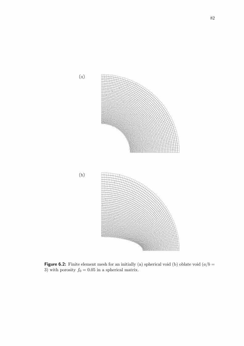
82
Figure 6.2: Finite element mesh for an initially (a) spherical void (b) oblate void (a/b =3) with porosity f0 = 0.05 in a spherical matrix.

83
Figure 6.3: Stress-strain curves of a cell volume containing a single void showing influ-ence of plastic dilatancy β under ψ = 0. σ0/E = 0.01, ν = 0.4, N = 0 for f0 = 0.01 withψα = 0
◦, 15◦.
at all times. Under axisymmetric deformation, the remote strain state is fully specified
by ψ and one strain parameter. When ψ = 1, the loading is equi-triaxial straining in
the sense of three dimensions. Uniaxial straining is specified for ψ = 0.
Recall that under initial loading, the overall stress-strain behavior of a voided cell
can be described by the Hook’s law with effective elastic moduli. For the understudied
axisymmetric deformation, the strain ratio ψ for spherical voids is related to the stress
triaxiality T by
ψ =3T − κ
3T + 2κwith κ =
1 + ν∗
1− 2ν∗ (6.17)
for Σz > Σρ. In the above ν∗ represents the effective Poisson’s ratio
ν∗ =ν (14− 10ν) + f (1 + ν) (3− 5ν)14− 10ν + f (1 + ν) (13− 5ν) (6.18)
(see Tandon and Weng, 1988). This relation will be used to check the numerical results
in this section.
6.4.1 Initially spherical voids
Figure 6.3 shows the macroscopic stress-strain behavior of a single void cell with initially
spherical voids of porosity f0 = 0.01. The unit-cell is specified by parameters: σ0/E =
0.01, ν = 0.4 and N = 0, which are representative of polymeric materials. The effects
of plastic dilatancy β are studied for two typical pressure-sensitive levels: ψα = 0◦
and 15◦. Results show that increasing dilation angle ψβ for a fixed friction angle ψα
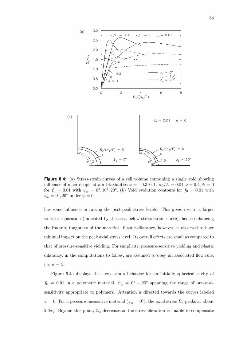
84
Figure 6.4: (a) Stress-strain curves of a cell volume containing a single void showinginfluence of macroscopic strain triaxialities ψ = −0.3, 0, 1. σ0/E = 0.01, ν = 0.4, N = 0for f0 = 0.01 with ψα = 0◦, 10◦, 20◦. (b) Void evolution contours for f0 = 0.01 withψα = 0
◦, 20◦ under ψ = 0.
has some influence in raising the post-peak stress levels. This gives rise to a larger
work of separation (indicated by the area below stress-strain curve), hence enhancing
the fracture toughness of the material. Plastic dilatancy, however, is observed to have
minimal impact on the peak axial stress level. Its overall effects are small as compared to
that of pressure-sensitive yielding. For simplicity, pressure-sensitive yielding and plastic
dilatancy, in the computations to follow, are assumed to obey an associated flow rule,
i.e. α = β.
Figure 6.4a displays the stress-strain behavior for an initially spherical cavity of
f0 = 0.01 in a polymeric material, ψα = 0◦ − 20◦ spanning the range of pressure-sensitivity appropriate to polymers. Attention is directed towards the curves labeled
ψ = 0. For a pressure-insensitive material (ψα = 0◦), the axial stress Σz peaks at about
2.6σ0. Beyond this point, Σz decreases as the stress elevation is unable to compensate

85
for the softening from void growth. As the pressure-sensitivity of the matrix material
increases to ψα = 10◦, Σz peaks at around 2σ0. With a higher pressure-sensitivity level
of ψα = 20◦, the peak Σz is further lowered to 1.5σ0. Similar effects of ψα are observed
for ψ = 1 and −0.3. While the peak axial stress level is weakly dependent on ψ, the
strain level associated with the peak Σz increases substantially with a change in the
strain state from ψ = 1 to ψ = −0.3.The peak axial stress is associated with rapid unstable void growth. This phenom-
enon can be seen from the void evolution contours in Fig. 6.4b for ψα = 0◦ and 20◦,
under ψ = 0. The dotted lines in the figure depict the void evolution at the peak axial
stress level. Observe the marginal void growth for both ψα = 0◦ and 20◦ prior to this
peak axial stress level. Beyond this point, void growth becomes very rapid (see evolution
contours for Ez/(σ0/E) = 4 and 6). The extent of void growth (for a fixed strain level)
is reduced with an increase in pressure-sensitivity.
The peak axial stress-strain results for metallic materials, represented by σ0/E =
0.002, ν = 0.3, are summarized in Table 6.1 for typical initial porosity levels of f0 = 0.001
and f0 = 0.01. A moderate strain hardening parameter of N = 0.1 is assumed. Friction
angles of ψα = 0◦—8◦ is in the range relevant to metallic materials. Observe that in
spite of the low pressure-sensitivity levels for metallic materials, the associated drop in
the sustainable axial stress Σz with increasing ψα is considerably large. This suggests
that the pressure-sensitivity effect, wherever it exists, should be taken into account.
This finding is also supported in Spitzig and Richmond (1984), where the importance
of the tension-compression strength-differential in both steel and aluminum alloys was
recognized.
6.4.2 Initially ellipsoidal voids
For uniformly distributed voids in a matrix material, void growth and coalescence ahead
of a crack under mode I dominant loading can be evaluated by subjecting a representative
unit-cell containing a single cavity to uniaxial straining, ψ = 0 (see Zhang et al., 2002).
Void shape effects pertaining to a polymeric material (σ0/E = 0.01, ν = 0.4, N = 0)
with f0 = 0.05 and a metallic material (σ0/E = 0.002, ν = 0.3, N = 0.1) with f0 = 0.005
for ψ = 0 are discussed in this section.

86
Table 6.1: Peak axial stress for σ0/E = 0.002, ν = 0.3, N = 0.1
Porosityf0
Strain Stateψ
Peak Σz/σ0ψα = 0
◦ 4◦ 8◦CorrespondingEz/(σ0/E)
ψα = 0◦ 4◦ 8◦
0.001−0.301
4.95 4.28 3.715.11 4.38 3.774.89 4.22 3.60
3.26 3.46 3.761.32 1.24 1.190.47 0.40 0.35
0.01−0.301
3.65 3.19 2.813.80 3.32 2.933.62 3.16 2.78
3.66 4.06 4.661.49 1.54 1.680.51 0.54 0.59
Prior to discussing the void shape effects, the stress triaxiality T for spherical voids
in polymeric and metallic materials are first examined for verification purposes. Under
initial loading, the stress triaxiality for polymeric materials (computed from the inverse
gradient of the curve for a/b = 1, ψα = 0◦ in Fig. 6.5b) was observed to be approximately
constant at T = 2.06. A similar computation performed for metallic materials showed
the stress triaxiality under initial loading to be around T = 1.08. Substituting the
corresponding ν and f0 values into (6.17) and (6.18), the theoretical values of T =
1.88 and 1.08 are respectively obtained for polymeric and metallic materials. These
theoretical values are in close agreement with the numerical results.
Figure 6.5 displays the void shape effects for a cavity in a polymeric material. Results
show that a larger void aspect ratio for oblate voids (a > b) significantly reduces the
sustainable peak mean stress level (Fig. 6.5a). Herein, this peak mean stress level is
termed as the critical stress Σcm responsible for rapid void growth. As a/b increases from
1 to 9 for ψα = 0◦, Σcm drops by nearly 50% to about 0.85σ0, while the sustainable peak
deviatoric stress is lowered by more than 60% to 0.22σ0 (Fig. 6.5b). When coupled
with a moderately pressure-sensitive matrix of ψα = 10◦, Σcm and the peak deviatoric
stress are further reduced to about 0.68σ0 and 0.19σ0 respectively. The reduction in
both hydrostatic and deviatoric stresses in the cell suggest oblate voids strongly affect
the cell’s stress carrying capacity and void growth.
The critical mean stress for several void shapes in a metallic cell with f0 = 0.005
are summarized in Table 6.2. The effects of void shape are comparatively less severe in
metallic materials than in polymeric materials. In metallic materials, pressure-sensitive
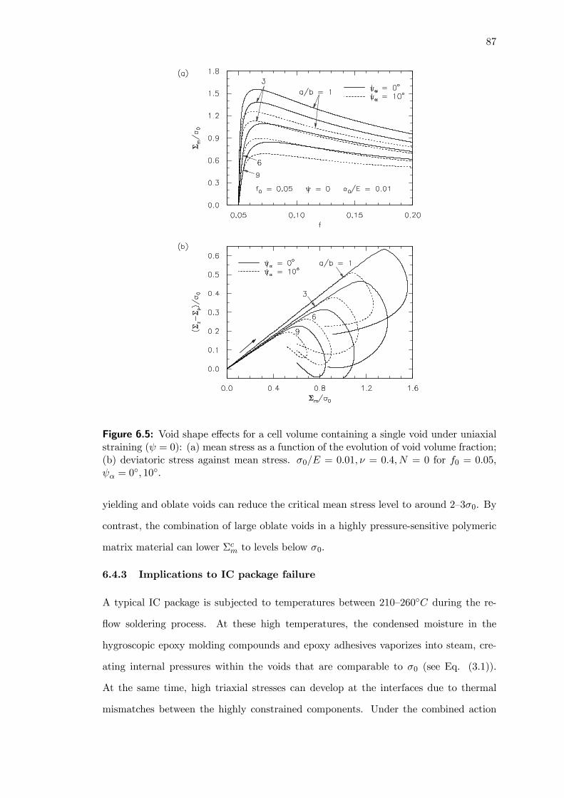
87
Figure 6.5: Void shape effects for a cell volume containing a single void under uniaxialstraining (ψ = 0): (a) mean stress as a function of the evolution of void volume fraction;(b) deviatoric stress against mean stress. σ0/E = 0.01, ν = 0.4, N = 0 for f0 = 0.05,ψα = 0
◦, 10◦.
yielding and oblate voids can reduce the critical mean stress level to around 2—3σ0. By
contrast, the combination of large oblate voids in a highly pressure-sensitive polymeric
matrix material can lower Σcm to levels below σ0.
6.4.3 Implications to IC package failure
A typical IC package is subjected to temperatures between 210—260◦C during the re-
flow soldering process. At these high temperatures, the condensed moisture in the
hygroscopic epoxy molding compounds and epoxy adhesives vaporizes into steam, cre-
ating internal pressures within the voids that are comparable to σ0 (see Eq. (3.1)).
At the same time, high triaxial stresses can develop at the interfaces due to thermal
mismatches between the highly constrained components. Under the combined action

88
Table 6.2: Critical mean stress for several void shapes under ψ = 0. σ0/E = 0.002, ν =0.3, N = 0.1, f0 = 0.005.
Pressure-Sensitivityψα
Critical Mean Stress Σcm/σ0a/b = 1/9 1 9 15
0◦
4◦
8◦
3.64 3.87 3.21 2.893.20 3.40 2.84 2.572.83 3.00 2.53 2.30
of thermal stress and high vapor pressure, both pre-existing and newly nucleated voids
grow rapidly and coalesce. Insights into the thermal- and moisture-induced failures in
plastic packages can be found in Chapters 3—5.
Traction-free void. The thermal-induced voiding phenomenon described above is
studied by subjecting a cavity in a polymeric material (σ0/E = 0.01, ν = 0.4, N = 0) to
the triaxial strain state ψ = 1. The coupled effects of void shape and initial porosity on
Σcm are summarized in Fig. 6.6a. The computed Σcm for a/b = 1, ψα = 0
◦ closely matches
the radial equilibrium solution described in (B.7) in Appendix B. The cavitation stress is
effectively reached as f0 approaches 0. For the purpose of discussion, plots for f0 = 10−4
are representative of the cavitation stress envelope for the unit-cell — these stress levels
will trigger the rapid nucleation and growth of microvoids in an infinite matrix. A
discussion on microvoid interaction effects will follow in Section 6.5. As compared to
the effects of α, cavitation stress is a weak function of void shape. As f0 increases,
however, the effects of void shape become more interesting. For example, a void aspect
ratio of a/b = 15 for f0 = 0.05 will cause a two-fold drop in the critical mean stress
level for a spherical void of the same porosity. The effects of void shape are especially
important in packaging problems, since the adhesives and molding compounds in plastic
packages are highly porous with typical f0 ranging between 1% to 5%. Under sufficiently
high levels of pressure-sensitivity, the mechanical strength of the oblate cavity is further
lowered with Σcm falling below σ0 (see plots for ψα = 20◦). While results also show that
prolate voids can lower the critical mean stress level of the voided cell, the observed
effects are much smaller than oblate voids (compare plots for a/b = 1/6 and a/b = 6).
For completeness, the combined effects of porosity and pressure-sensitivity on the
critical mean stresses for a cavity in a polymeric material for ψ = 0 are summarized

89
Figure 6.6: Critical mean stress plots showing (a) void shape effects with void volumefraction under triaxial straining (ψ = 1); (b) void volume fraction influence with frictionangle under uniaxial straining (ψ = 0). σ0/E = 0.01, ν = 0.4, N = 0.
in Fig. 6.6b. The associated drop in Σcm with increasing ψα is significant across all
porosity levels. For f0 = 0.05 with ψα = 0◦, unstable void growth can be triggered at a
critical stress level of Σcm = 1.5σ0 as compared to Σcm = 3σ0 for a void-free cavity (see
f0 = 10−5, ψα = 0
◦). When coupled with a pressure-sensitive matrix of ψα = 15◦− 20◦,
the cavity can fail by void rupture at stress levels close to σ0.
To gain some insights into the effects of pressure-sensitivity, the spherically symmet-
ric void growth in a perfectly-rigid plastic matrix with void volume fraction f , subjected
to internal pressure p and externally applied radial stress Σm, is next considered. The
radial equilibrium solution, which provides an asymptotic upper-bound solution for the
problem at hand, is presented in Appendix B. From (B.6), one can see that the macro-
scopic mean stress (i.e. σAr ) is a decreasing function of α when p = 0, which explains

90
the drop in Σcm as ψα increases from 0◦ to 20◦. See the plots for ψ = 1 in Fig. 6.4a and
a/b = 1 in Fig. 6.6a. Similar effects of pressure-sensitivity are anticipated under ψ = 0
(Fig. 6.6b).
Influence of internal pressure. Insights into the moisture-induced failure of IC
packages are next obtained by considering a void-containing unit-cell filled with water
vapor. Guo and Cheng (2002) showed that the vapor pressure p for fully vaporized
moisture can be derived from the ideal gas law and is dependent on the current void
volume fraction f . This holds true for low moisture content. If the void contains high
moisture content, the moisture may not fully vaporize leaving a two-phase mixture of
water and vapor gas. In such cases, vapor pressure can be taken to be a constant
(see phase diagram of water). In this study, vapor pressure is assumed to be constant
during the deformation to describe the high moisture content case. The void surface is
subjected to a Cauchy-type traction: t = −pn where n is the inward normal vector inthe current deformed configuration. This pressure p is proportionally imposed, with the
outer boundaries of the cell remaining traction-free.
Figure 6.7a shows the pressure-induced void growth for a cavity in a polymeric
material. A saturated peak pressure is observed which is associated with rapid unstable
void growth; this pressure peak, termed as the critical pressure pc, is synonymous with
the critical mean stress defined in the earlier discussions. For ψα = 0◦, pc closely matches
the radial equilibrium solution described in (B.7) in Appendix B for the range of initial
porosities considered in this chapter. Observe that pc is a strong function of the initial
porosity f0. A larger f0 will severely lower the critical stress level responsible for void
rupture. As α increases, the critical pressure correspondingly increases. For example, for
f0 = 0.01, an increase in ψα from 0◦ to 20◦ raises pc from 2.5σ0 to 3.3σ0. This suggests
that the effects of vapor pressure are less severe for pressure-sensitive polymers, like the
die-attach or molding compound in electronic packages.
The effects of α under internal pressure loading are different from that observed
under remote tensile loading. To explain this phenomenon, reference is again made to
the radial equilibrium solution in (B.6). By analogy with the Gurson constitutive model
(Gurson, 1977), one notes that the internal pressure acting on the spherical cavity

91
Figure 6.7: Internal pressure effects for ψα = 0◦ and 20◦ on (a) spherical void growth
with various f0; (b) void growth with varying void shapes for f0 = 0.05. σ0/E = 0.01, ν =0.4, N = 0.
has a two-fold effect: it increases the matrix flow stress, as indicated by the left-hand
denominator of (B.6), and also acts as a driving force for void growth. An increase in
pressure-sensitivity α further elevates the matrix flow stress, which in turn contributes
to the increase in the critical pressure pc in Fig. 6.7a.
Figure 6.7b shows the influence of void aspect ratio for an internally pressured el-
lipsoidal cavity of porosity f0 = 0.05. Results show a marked reduction in the critical
pressure for increasingly oblate voids, suggesting the critical pressure to be a strong
function of void shape. A comparison between the plots for ψα = 0◦ and ψα = 20◦,
however, shows the effects of pressure-sensitivity to be apparent only when the initial
void shapes are near spherical.

92
Figure 6.8: (a) Finite element mesh for a cell element containing a large void withf0 = 0.005, and a population of discrete microvoids; (b) close-up of the mesh aroundone of the microvoids.
6.5 Multiple size-scale void interaction
The cell study in Section 6.4 considers a uniform distribution of voids in the matrix
material. In actual ductile solids, the nonuniform distribution of voids of varying size-
scales can have an impact on the overall stress-carrying capacity of the solid.
This section examines the void interaction effects in porous ductile pressure-sensitive
solids containing two populations of cavities. Metallic alloys typically contain a dual pop-
ulation of voids of different size-scales which originate from various inclusions (e.g. MnS
inclusions and carbides in steel). In rubber modified epoxies, cavitated rubber blends or
the decohesion of filler particle/polymeric matrix interfaces constitute the larger voids,

93
while the deformation mechanism of crazing can induce microvoid formation in the ma-
trix material. Similar to Faleskog and Shih (1997), the representative material volume
consists of a single large void of f0 = 0.005 with a population of discrete microvoids
placed at locations where cavitation instability could occur, i.e. along the horizontal
axis and along the diagonal of the cell (see Fig. 6.8a). Each microvoid has an initial
void volume fraction fm0 = 1.75× 10⁻⁴ (Fig. 6.8b). For comparable study of microvoidinteraction, a similar unit-cell consisting of a single large void of the same f0 without
microvoids is also used. In both cases, the finite element mesh employs six-noded plane
strain triangular elements. Roller boundary conditions are applied along the symmetric
planes of the quarter geometry of the cell volume to be analyzed. On a macroscale, the
unit-cell is subjected to a biaxial strain state ψ = Exx/Eyy, i.e. Ezz = 0, with coor-
dinate directions as indicated in Fig. 6.8. These are the logarithmic strains, and the
work conjugate quantities Σxx and Σyy are the Cauchy stress defined as the tractions
averaged over the deformed length of the cell in the x and y directions respectively.
Investigations are carried out for metallic and polymeric materials, specified by the
parameters: σ0/E = 0.002, ν = 0.3, and σ0/E = 0.01, ν = 0.4 respectively. In both
cases, a moderate hardening parameter N = 0.1 is used. Xia and Shih (1995b) reported
that the range of strain biaxialities −0.7 ≤ ψ ≤ 0 corresponds to that for a growingcrack. This study focuses on the two limits of strain biaxiality: ψ = 0 and ψ = −0.7.
Figure 6.9a displays the stress-strain behavior of the cell in the metallic material
for ψ = 0. Results show that the presence of microvoids greatly reduces the stress-
carrying capacity of the cell across the range of pressure-sensitivity levels considered —
the peak stress of Σyy is lowered, with a dramatic drop in the post-peak stress load.
For example for ψα = 4◦, the presence of microvoids reduces the peak Σyy from 3.0σ0
to 2.7σ0. The drop in the post-peak stress load is more pronounced, with Σyy falling
by nearly 30% at Eyy = 9σ0/E. Results further show that as ψα increases, the overall
stresses in the cell correspondingly decreases. The stress-strain behavior of the cell in
the metallic material for low strain biaxiality ψ = −0.7 is shown in Fig. 6.9b. Microvoidinteraction is observed to be significant for ψα = 0
◦. As ψα increases however, the effect
of microvoid interaction diminishes.
The stress-strain behavior of the cell in the polymeric material is shown in Fig. 6.10a

94
Figure 6.9: Stress-strain curves of a cell volume with discrete microvoids for several ψα
for (a) ψ = 0; (b) ψ = −0.7. σ0/E = 0.002, ν = 0.3, N = 0.1.
for ψ = 0, and Fig. 6.10b for ψ = −0.7. While the basic trend of these plots followclosely to that for the metallic material in Fig. 6.9, microvoid interaction in polymeric
material for ψ = 0 can lower Σyy to levels comparable to the initial yield strength.
Observe the rapid drop in Σyy to levels below σ0 at Eyy = 3σ0/E for the cell in the
polymeric material with microvoids. Moreover, the higher initial porosities present in
actual polymers can result in much lower stress levels than that predicted in Fig. 6.10
(see f0 effects in Fig. 6.6).
Figure 6.11a displays the void evolution contours for the cell in the polymeric mate-
rial for ψ = 0. For both ψα = 0◦ and 15◦, negligible voiding activity is observed before
the peak stress is reached (Eyy = σ0/E). In the post-peak stress regime (Eyy = 2σ0/E),
microvoids horizontal to the main cavity experience cavitation instability — these ini-
tial minute voids can grow to volume fractions comparable to the main cavity (see
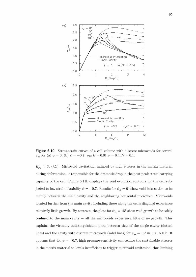
95
Figure 6.10: Stress-strain curves of a cell volume with discrete microvoids for severalψα for (a) ψ = 0; (b) ψ = −0.7. σ0/E = 0.01, ν = 0.4, N = 0.1.
Eyy = 3σ0/E). Microvoid cavitation, induced by high stresses in the matrix material
during deformation, is responsible for the dramatic drop in the post-peak stress-carrying
capacity of the cell. Figure 6.11b displays the void evolution contours for the cell sub-
jected to low strain biaxiality ψ = −0.7. Results for ψα = 0◦ show void interaction to be
mainly between the main cavity and the neighboring horizontal microvoid. Microvoids
located further from the main cavity including those along the cell’s diagonal experience
relatively little growth. By contrast, the plots for ψα = 15◦ show void growth to be solely
confined to the main cavity − all the microvoids experience little or no growth. Thisexplains the virtually indistinguishable plots between that of the single cavity (dotted
lines) and the cavity with discrete microvoids (solid lines) for ψα = 15◦ in Fig. 6.10b. It
appears that for ψ = −0.7, high pressure-sensitivity can reduce the sustainable stressesin the matrix material to levels insufficient to trigger microvoid cavitation, thus limiting

96
Figure 6.11: Contour maps of deformed void shapes for ψα = 0◦ and 15◦ at severalloading instants for (a) ψ = 0; (b) ψ = −0.7. σ0/E = 0.01, ν = 0.4, N = 0.1.
the extent of microvoid interaction.
6.6 Concluding remarks
A numerical study pertaining to the effects of pressure-sensitivity and plastic dilatancy
on void growth and interaction has been performed. Homogeneous deformation is first
assumed by subjecting a representative unit cell, containing a single void, to physical
stress states similar to highly stressed regions ahead of the crack. The computations show
plastic dilatancy to have some effect in raising the post-peak stress levels, resulting in a
larger work of separation. The effects of pressure-sensitivity are more pronounced: under
an externally applied load, an increase in pressure-sensitivity of the material severely
lowers its stress-carrying capacity. The mechanical strength of the material is further

97
weakened by an increasingly oblate void. In polymeric materials, the higher initial
porosities and pressure-sensitivity levels (compared to metallic materials) can reduce
the critical stress responsible for void instability to levels comparable to the initial yield
strength. This study also suggests that the damaging effects of internal pressure can
be less severe for a pressure-sensitive material. This observation is of importance in IC
packages, since the porous adhesives and molding compounds are often susceptible to
moisture-induced void growth.
The void interaction effects in pressure-sensitive dilatant solids containing two pop-
ulation of cavities of different size-scales have also been studied. The microvoids can
originate from inclusions and second-phase particles in metals, or from crazing in poly-
mers. The study shows that microvoid interaction and pressure-sensitivity can work in
concert in reducing the stress carrying capacity of the material. The former is respon-
sible for the post-peak stress drop while the latter controls the sustainable peak stress
level. The relative contribution of these parameters is observed to be loading dependent.

98
CHAPTER 7
PRESSURE-SENSITIVE DUCTILE LAYERS:
MODELING THE GROWTH OF EXTENSIVE
DAMAGE
Research scope
The role of pressure-sensitive yielding in polymers has been widely studied by way ofcrack-tip fields in unvoided materials. Typical polymeric adhesives contain numerouspores and cavities. In this chapter, the mechanisms of void growth and coalescencein ductile polymeric adhesives are explored, with emphasis on the contributions ofpressure-sensitivity and plastic dilatancy to the damage zone extension.
Main findings
Under an associated flow rule, pressure-sensitivity not only intensifies damage levelsbut also increases its spatial extent several fold. The damage level as well as its spatialextent is found to be even greater when a non-associated flow rule is deployed.
Extracts from this chapter can be found in Journal Papers [4, 6] and Conference Papers[5, 7].
7.1 Introduction
Mechanism-based computational models are highly attractive tools for the prediction of
fracture and failure of structural components. One widely accepted approach for model-
ing ductile fracture is to idealize the fracture process zone by confining void growth and
coalescence in the material to a single row of void-containing cells ahead of the crack-tip
(Xia and Shih, 1995a; Chapters 4 and 5). The progressive damage of these compu-
tational cells is governed by the Gurson constitutive model (Gurson, 1977). Recent
years have witnessed several attempts to replicate the exact void growth behavior using
discrete voids. Tvergaard and Hutchinson (2002) introduced a population of discrete
cylindrical voids ahead of a crack to study the mechanisms of ductile crack initiation and
growth. They observed that the void interaction effects resulted in two distinct fracture
mechanisms: (i) near-tip void growth and coalescence, and (ii) multiple void interaction
mechanisms. The transition between these two mechanisms is primarily governed by

99
the initial porosity. Other studies using discrete voids to model ductile fracture were
conducted by Kim et al. (2003) and Gao et al. (2005). These studies were, however, con-
fined to cracks in homogeneous ductile metals. The present work focuses on constrained
polymeric layers.
The deformation of polymeric materials and adhesives differs considerably from met-
als. Aside from exhibiting large elastic strains prior to yield, the yield stress of polymers
displays strong pressure-sensitivity (Quinson et al., 1997). In addition, the plastic flow
of polymers is non-volume preserving (G’Sell et al., 2002). The initial yield strains of
polymers can reach 1—5%, with friction angles (related to pressure-sensitivity levels)
ranging from 0—23◦. Focusing on the large elastic strain effects for pressure-insensitive
solids, Tvergaard (1999) found the critical cavitation stress to decay strongly with the
increase in initial yield strain. The computations in Chapter 6 showed that increasing
pressure-sensitivity severely reduced the stress-carrying capacity of a porous material,
while multiple void interactions led to the sharp post-peak stress drop which in turn
triggered rapid failure. In contrast, plastic dilatancy was found to have some effect in
raising the post-peak stress levels, resulting in a larger work of separation.
This chapter examines the mechanisms of void growth and coalescence in pressure-
sensitive ductile layers. A crack at the center of the adhesive is considered, with the
adhesive-substrate interfaces assumed to be strongly-bonded. The damage process zone
in the adhesive is modeled by a single row of discrete voids placed ahead of the crack.
The adhesive joint is subjected to small-scale yielding conditions. The objective is to in-
vestigate how several distinctive characteristics of polymers, such as pressure-sensitivity
and plastic dilatancy, influence void growth and coalescence in adhesive joints, and how
these parameters contribute to the formation of extended damage zones.
7.2 Problem modeling
Finite element analysis of a cracked, sandwiched adhesive layer subjected to mode I
K-field loading under small-scale yielding conditions is carried out. The joint comprises
a ductile film of thickness h joining two elastic substrates. The two substrates have
identical properties. They are elastic isotropic materials with Young’s modulus, Es, and
Poisson’s ratio, νs. The elastic properties of the film are designated by E and ν. The

100
plastic behavior of the film is described by a pressure-dependent yield criterion under
a non-associated flow rule. Details are given in Eqs. (2.4) — (2.9) in Chapter 2. This
pressure-dependent model is included in the material library in ABAQUS Version 6.3.1
(2002).
The boundary layer configuration is depicted in Fig. 7.1a. Along the remote cir-
cular boundary, mode I elastic K-field displacements are prescribed under plane strain
conditions (see Eq. (3.5)). The relationship between the mode I stress-intensity factor
KI and the energy release rate G (and hence the J-integral) is given by (3.6).
7.2.1 Discrete void implementation
Xia and Shih (1995a) simplified the ductile fracture process by placing a single row
of void-containing cells ahead of the crack-tip; this layer of computational cells was
representative of the fracture process zone. This approach was formerly adopted in
Chapters 4 and 5 to study crack propagation along the adhesive-substrate interface. In
this chapter, the fracture process zone is modeled using discrete cylindrical voids.
Damage in the adhesive is confined to a row of unit-cells placed ahead of the crack-
tip. Each unit-cell is of dimensions D by D (related to void spacing), and contains a
discrete cylindrical void of initial radius R0. This arrangement of voids is illustrated
by a close-up view in Fig. 7.1a for D = h/2. The initial void volume fraction is given
by f0 = πR20/D2. The crack-tip has a small initial root radius r0, with the distance
between the crack-tip and nearest void fixed at D. Previous studies have shown the
influence of the notch-tip radius r0 to be negligible for small r0/D. In this study, r0 is
fixed as 0.04D.
The macroscopic stress of each unit-cell is computed from
Σij =1
V
ZVσijdv (7.1)
where σij represents the local Cauchy stress within a voided cell, and V is the cell volume
in the current deformed configuration with unit thickness in the axial direction. The
macroscopic mean stress is given by Σm = Σkk/3. The current void volume fraction
is calculated from f = Vf/V where Vf represents the current deformed void volume
obtained by numerical integration. The macroscopic stress distribution over the layer
of cells, together with the current porosity f , can be employed to describe adhesive

101
Figure 7.1: (a) An adhesive (with a centerline crack) bonded to two elastic substratessubject to remote elastic KI field. (b) Close-up view of the finite element mesh near thecrack-tip for f0 = 0.05, D = h/2.
102
behavior and damage.
Figure 7.1b displays the close-up view of the finite element mesh near the crack-tip
for f0 = 0.05, D = h/2. By taking advantage of symmetry, only one half of the geometry
needs to be modeled. In this example mesh, a total of 23 voids is used. For D = h, h/4
and h/8, the number of voids introduced are 11, 47, and 95 respectively. It should be
noted that the process zone length in a constrained layer can be several times longer
than that in a homogeneous material due to the high stress triaxiality inherent in the
former. As such, a greater number of voids are required to model the damage process
zone in this work, than for fracture studies on cracks in homogeneous materials (e.g.
Tvergaard and Hutchinson, 2002).
To prevent spurious mesh dependency from the cell size study, a convergence analysis
is systematically performed by examining the effects of mesh refinement. Convergence
is considered attained when no change in the damage distribution with mesh refine-
ment is observed. The mesh contains 4-node bilinear quadrilateral hybrid plane strain
elements. The computations are performed within the finite strain setting using the
general-purpose finite element program ABAQUS Version 6.3.1 (2002).
7.2.2 Internal pressure
At reflow temperatures, the condensed moisture in the voids vaporizes into steam, in-
ducing internal pressures that can reach 3-6 MPa (Liu and Mei, 1995; Keenan et al.,
1978). Such levels are comparable to the yield stresses of thin film adhesives and mold-
ing compounds at Tg (see Eq. (3.1)). If each void in the adhesive contains high moisture
content, the moisture may not fully vaporize leaving a two-phase mixture of water and
vapor gas. In such cases, vapor pressure can be taken to be a constant. The compu-
tations in Sections 7.3—7.6 assume that the void surfaces remain traction-free, i.e. no
internal pressure. In Section 7.7, the effects of constant vapor pressure are examined to
describe the high moisture content case: each void surface is subjected to the identical
constant pressure p, with a Cauchy-type traction
t = −pn (7.2)
where n is the inward normal vector in the current deformed configuration. This pressure
p is proportionally imposed up to the desired level, before imposing the KI displacement

103
field in (3.5).
7.2.3 Model parameters
Polymeric adhesives contain numerous pores and cavities of various size scales. The
initial porosity f0 can vary from less than 0.5% for the microvoids, to 20—40% for cav-
itated rubber particles in glassy polymers. From moisture analysis, the estimated f0
for the die-attach and molding compound in PBGA packages ranges from 1—5%. This
study considers the initial porosity range of 0.5—5% for the polymeric adhesive film.
The properties of the film are specified by the parameters σ0/E = 0.01, ν = 0.4, and
N = 0.1. The elastic modulus mismatch between the film and the substrate is taken as
Es/E = 10, with νs = 0.3. These values are representative of polymer-silicon joints in
IC packages.
In the next section, a unit-cell study is conducted to characterize the effects of
pressure-sensitivity and plastic dilatancy on the cell behavior ahead of the crack. At the
same time, the radial solution for void growth in an axisymmetric plane strain unit-cell
is derived in Appendix C. Section 7.4 describes the failure mechanisms in pressure-
insensitive adhesive joints, while Section 7.5 discusses the contribution of several key
parameters to the damage evolution in pressure-sensitive adhesives. In Section 7.6,
a failure criterion for crack growth is proposed, and the fracture toughness trends are
studied. Thereafter, Section 7.7 examines the effects of constant vapor pressure. Section
7.8 concludes this chapter with a short summary.
7.3 Unit-cell behavior
Insights into the effects of pressure-sensitivity α and plastic dilatancy β on void growth
and material failure are first obtained from a unit-cell study. Consider a square unit-cell
of dimensions D×D that contains a single cylindrical void. Roller boundary conditions
are applied along the symmetric planes of the quarter geometry of the cell volume to
be analyzed (see insert in Fig. 7.2). The unit-cell is subjected to equibiaxial straining
in Fig. 7.2a to study the high triaxiality induced void growth. It is also subjected to
uniaxial straining in Fig. 7.2b to simulate void growth and coalescence ahead of a crack
under mode I dominant loading. In both cases, the cell is specified by σ0/E = 0.01 and
N = 0, with f0 = 0.05. The overall stresses in the cell are computed from (7.1).

104
Figure 7.2: Effects of pressure-sensitivity and plastic dilatancy for a unit-cell volumecontaining a single void. (a) In-plane mean stress versus porosity f for equibiaxialstraining under associated flow. (b) Macroscopic stress-strain curves for uniaxial strain-ing under non-associated flow. σ0/E = 0.01, N = 0, f0 = 0.05.
Concurrently, the analytical solution for a plane strain hollow cylinder subjected
to internal pressure p and remotely applied radial stress Σρ is derived in Appendix
C. Attention is focused on void growth in a fully-plastic matrix under both associated
normality flow (α = β) and incompressible plastic flow (β = 0). In addition, the solution
for void growth in an incompressible elastic-plastic matrix (α = β = 0) is presented.
These analytical results are compared against finite element computations for traction-
free void surface, i.e. p = 0.
7.3.1 Equibiaxial straining
Figure 7.2a displays the in-plane mean stress (Σx + Σy)/2σ0 versus void growth f for
three pressure-sensitivity levels represented by friction angles: ψα = 0◦, 10◦ and 20◦

105
under an associated flow (α = β). The numerical results show that an increase in ψα
from 0◦ to 20◦ reduces the peak stress level responsible for rapid void growth by about
30%. A comparison between the fully-plastic solution (Eq. (C.1) in Appendix C) and
the finite element results in Fig. 7.2a shows the former to provide the upper limit-
load of the cell. The difference between both solutions can be mainly attributed to the
shape effects of the cell boundary: circular symmetry for the analytical derivation, and
square symmetry for the finite element solution. These effects are reduced when the
initial porosity becomes vanishingly small, i.e. f0 → 0, and close agreement between the
numerical results and the fully-plastic analytical solution is obtained. It is also observed
that the elastic-plastic solution (Eq. (C.11) in Appendix C) agrees with the fully-plastic
solution for ψα = ψβ = 0◦ in the post-peak regime.
7.3.2 Uniaxial straining
Figure 7.2b displays the effects of plastic dilatancy β, for a non-associated flow (β < α),
on the macroscopic stress-strain response of the single void cell under uniaxial straining.
The three benchmark curves for ψα(= ψβ) = 0◦, 10◦ and 20◦ are displayed. The peak
stresses for ψβ < ψα are no different from those for ψβ = ψα, showing that the peak
stress level is unaffected by β. However, the stress carrying capacity in the post-peak
stress regime are slightly lower when ψβ < ψα. These trends suggest that the work of
separation (as indicated by the area below stress-strain curve) is lower for β < α.
The fully-plastic analytical solution for work-rate equivalence given in (C.5) in Ap-
pendix C is next examined. Under uniaxial straining, Dpx = Dp
z = 0, whileDpy is required
to satisfy the work-conjugate stress Σy = Σρ in (C.1) in Appendix C. By setting p = 0
for the traction-free void, one can show that Σy/σ0 = 1.37, 1.12 for ψα = ψβ = 10◦,
20◦ with f = 0.05. These theoretical values are in good agreement with the peak stress
levels observed in Fig. 7.2b. From (C.1) and (C.7) in Appendix C, it is also observed
that the sum of the radial stress and internal pressure, Σρ + p, is a decreasing function
of α. Incompressible plastic flow (β = 0) exhibits a larger stress drop than the normality
flow (β = α) over the parametric range of 0 ≤ α ≤ 12 . This further confirms the numer-
ical results in Fig. 7.2b (compare the plots for ψβ = ψα = 10◦ and for ψβ = 0◦ and
ψα = 10◦).

106
Figure 7.3: Distribution of porosity f ahead of crack (X2 = 0) for D = h/4; σ0/E =0.01, N = 0.1 (a) f0 = 0.005; (b) f0 = 0.05.
In passing, it can be noted that the fully-plastic analytical solution derived in Ap-
pendix C provides good estimates of the stress levels in the unit-cell when the elastic
deformation is small. For materials with large elastic strains, larger deviation in the peak
stress levels between the fully-plastic solution and the numerical results are observed.
7.4 Failure mechanisms in pressure-insensitive adhesives
In a highly constrained adhesive, extensive void growth brings about volume increase
and material softening. Both these effects contribute to stress relaxation. This section
examines the competition between several failure mechanisms driven by the interplay
between stress relaxation due to extensive void growth, and stress elevation induced by
constrained plastic flow for α = β = 0.
Figure 7.3a displays the porosity distribution plots for polymer-silicon joints, with

107
f0 = 0.005 at a fixed cell size of D = h/4. The discrete points in the figure represent the
actual numerical values. At initial loads corresponding to J/(σ0h) = 0.057, voiding is
confined to the near-tip vicinity. At slightly higher loads of J/(σ0h) = 0.064, a two-fold
increase in the peak porosity is observed. At even higher loads of J/(σ0h) = 0.076, the
peak porosity increases to nearly 18 times its initial value. At such load levels however,
void growth and hence the extent of damage is limited to X1 < 4h.
One prominent feature is the emergence of the peak porosity centered at distance
X1 = h ahead of the crack for all four load levels. This phenomenon can be attributed
to the build-up of stress triaxiality some distances ahead of the crack in the highly
constrained adhesive (Varias et al., 1991). As voiding develops at the intervening zone,
the primary site of void activity at X1 = h is ultimately joined to the main crack, while
new damage sites are concurrently formed at locations even further ahead of the original
crack. This voiding pattern is referred to as the “multiple damage zone” mechanism.
Figure 7.3b shows the porosity distribution plots for f0 = 0.05. A zone of voiding
emanates from the crack at low loads. As the load increases, voids further ahead of
the crack also grow by significant amounts. The stress relaxation associated with this
pattern of voiding shifts the damage extent further ahead of the crack — from X1 = 5h
for J/(σ0h) = 0.041 to X1 = 10h for J/(σ0h) = 0.065. Unlike the low porosity adhesive,
very rapid growth of voids at the crack-tip results in material softening, and prevents
the built-up of high stress triaxiality in the constrained layer. Material closest to the
crack-tip experiences fastest void growth and failure progresses ahead continuously. This
pattern of adhesive failure is referred to as the “contiguous damage zone” mechanism.
Both the multiple damage zone and the contiguous damage zone mechanisms have been
experimentally observed in constrained epoxy adhesives (Chai, 1993).
It should be noted that the failure mechanisms observed in the constrained layer
configuration are different from those observed by Tvergaard and Hutchinson (2002) for
cracks in homogeneous materials. This can be attributed to the high stress triaxiality
inherent in the adhesive joint.
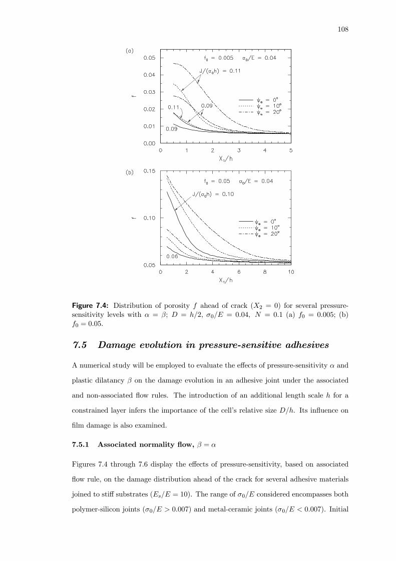
108
Figure 7.4: Distribution of porosity f ahead of crack (X2 = 0) for several pressure-sensitivity levels with α = β; D = h/2, σ0/E = 0.04, N = 0.1 (a) f0 = 0.005; (b)f0 = 0.05.
7.5 Damage evolution in pressure-sensitive adhesives
A numerical study will be employed to evaluate the effects of pressure-sensitivity α and
plastic dilatancy β on the damage evolution in an adhesive joint under the associated
and non-associated flow rules. The introduction of an additional length scale h for a
constrained layer infers the importance of the cell’s relative size D/h. Its influence on
film damage is also examined.
7.5.1 Associated normality flow, β = α
Figures 7.4 through 7.6 display the effects of pressure-sensitivity, based on associated
flow rule, on the damage distribution ahead of the crack for several adhesive materials
joined to stiff substrates (Es/E = 10). The range of σ0/E considered encompasses both
polymer-silicon joints (σ0/E > 0.007) and metal-ceramic joints (σ0/E < 0.007). Initial
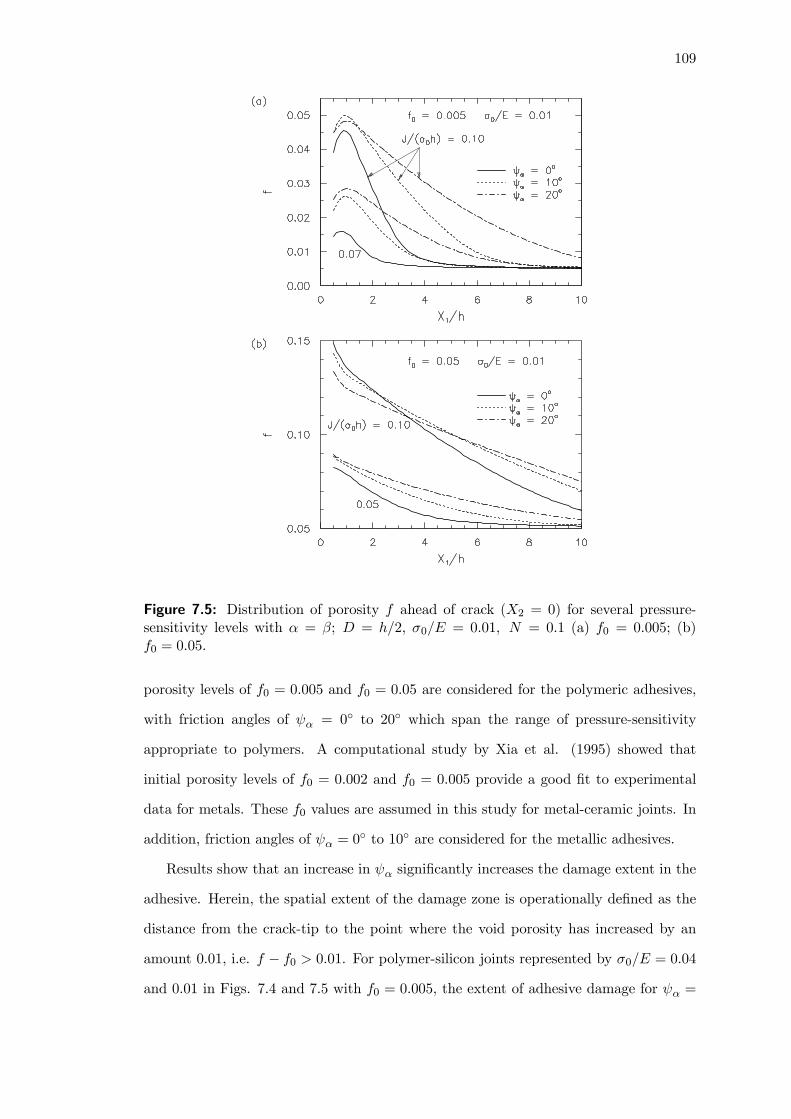
109
Figure 7.5: Distribution of porosity f ahead of crack (X2 = 0) for several pressure-sensitivity levels with α = β; D = h/2, σ0/E = 0.01, N = 0.1 (a) f0 = 0.005; (b)f0 = 0.05.
porosity levels of f0 = 0.005 and f0 = 0.05 are considered for the polymeric adhesives,
with friction angles of ψα = 0◦ to 20◦ which span the range of pressure-sensitivity
appropriate to polymers. A computational study by Xia et al. (1995) showed that
initial porosity levels of f0 = 0.002 and f0 = 0.005 provide a good fit to experimental
data for metals. These f0 values are assumed in this study for metal-ceramic joints. In
addition, friction angles of ψα = 0◦ to 10◦ are considered for the metallic adhesives.
Results show that an increase in ψα significantly increases the damage extent in the
adhesive. Herein, the spatial extent of the damage zone is operationally defined as the
distance from the crack-tip to the point where the void porosity has increased by an
amount 0.01, i.e. f − f0 > 0.01. For polymer-silicon joints represented by σ0/E = 0.04
and 0.01 in Figs. 7.4 and 7.5 with f0 = 0.005, the extent of adhesive damage for ψα =

110
10◦ is nearly twice that for ψα = 0◦ at equivalent external loading J/(σ0h). At higher
friction angles of ψα = 20◦, the damage extent increases by nearly four-fold that for
ψα = 0◦. The effects of pressure-sensitivity on the damage zone length are more severe
for low porosity adhesives. Interestingly, it is noted that an increase in ψα from 0◦
to 10◦ also induces a considerable increase in the process zone length for metal-ceramic
joints (Fig. 7.6). These pressure-sensitivity levels are in the range relevant to iron-based
metals and aluminum alloys (Spitzig and Richmond, 1984; Chapter 6).
At this point, reference is made with the experimental work of Du et al. (2000),
where a double-cantilever-beam test was conducted to study the process zone length
and thickness in rubber-modified epoxy. They showed that the steady-state process
zone could reach lengths of 4—12 times the process zone thickness D under quasi-static
loading conditions. This observation corroborates closely with the spatial extents of
damage revealed in this study. In addition, it is noted that the voiding patterns in Figs.
7.4 and 7.5 resemble the morphology of the fracture surfaces of rubber-modified epoxy
adhesives under high stress triaxiality (Imanaka et al., 2003).
Another interesting characteristic of pressure-sensitivity concerns its effects on the
damage intensity of the adhesive. At low to moderate load levels, increasing pressure-
sensitivity accelerates the near-tip void growth, resulting in higher peak porosity levels
in materials having larger α values. At higher load levels when a highly damage zone has
been established, the trend of increasing near-tip void growth with pressure-sensitivity
cannot be sustained, and the peak porosity levels of materials having lower α values
eventually exceed those for materials with larger α (see Figs. 7.5 and 7.6).
The above phenomenon can be understood by looking ahead to Fig. 7.8, which
shows the porosity and mean stress evolution plots for unit-cells ahead of the crack
for ψα = ψβ = 0◦ and 10◦. Focusing on fixed cell size of D = h/2, it is observed
that pressure-sensitivity significantly lowers the peak mean stress level responsible for
unstable void growth. As a result, initiation of rapid voiding for ψα = 10◦ occurs at
much lower J/(σ0h) than for ψα = 0◦. This explains the several fold increase in the
process zone length for pressure-sensitive adhesives in Figs. 7.4 — 7.6. For clarity, Table
7.1 summarizes the critical (or peak) mean stress Σcm and the J/(σ0h) at which Σcm
occurs for unit-cells ahead of the crack with different ψα. This table can be constructed

111
Figure 7.6: Distribution of porosity f ahead of crack (X2 = 0) for several pressure-sensitivity levels with α = β; D = h/2, σ0/E = 0.004, N = 0.1 (a) f0 = 0.002; (b)f0 = 0.005.
from similar plots to Fig. 7.8. At higher load levels sufficient to trigger rapid void growth
for ψα = 0◦, the rate of void expansion for ψα = 0
◦ is notably faster due to the higher
mean stress and constraint levels, eventually causing more localized damage at the near-
tip. These observations can also be anticipated from the analytical formulation of the
void growth rate for a fully-plastic matrix under normality flow conditions (Eq. (C.3)
in Appendix C). In reality, one would expect the damage levels for pressure-sensitive
adhesives to be consistently higher than for pressure-insensitive adhesives, since void
coalescence often occurs just beyond the critical stress Σcm.
7.5.2 Non-associated flow, β < α
The analysis in the above section employs an associated flow rule, i.e. β = α. While
these results represent the benchmark curves, experimental observations have shown
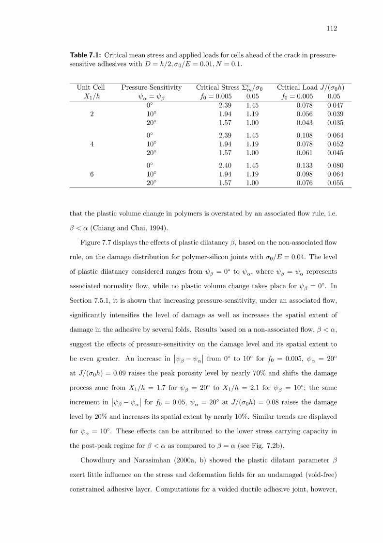
112
Table 7.1: Critical mean stress and applied loads for cells ahead of the crack in pressure-sensitive adhesives with D = h/2, σ0/E = 0.01, N = 0.1.
Unit CellX1/h
Pressure-Sensitivityψα = ψβ
Critical Stress Σcm/σ0f0 = 0.005 0.05
Critical Load J/(σ0h)f0 = 0.005 0.05
20◦
10◦
20◦
2.39 1.451.94 1.191.57 1.00
0.078 0.0470.056 0.0390.043 0.035
40◦
10◦
20◦
2.39 1.451.94 1.191.57 1.00
0.108 0.0640.078 0.0520.061 0.045
60◦
10◦
20◦
2.40 1.451.94 1.191.57 1.00
0.133 0.0800.098 0.0640.076 0.055
that the plastic volume change in polymers is overstated by an associated flow rule, i.e.
β < α (Chiang and Chai, 1994).
Figure 7.7 displays the effects of plastic dilatancy β, based on the non-associated flow
rule, on the damage distribution for polymer-silicon joints with σ0/E = 0.04. The level
of plastic dilatancy considered ranges from ψβ = 0◦ to ψα, where ψβ = ψα represents
associated normality flow, while no plastic volume change takes place for ψβ = 0◦. In
Section 7.5.1, it is shown that increasing pressure-sensitivity, under an associated flow,
significantly intensifies the level of damage as well as increases the spatial extent of
damage in the adhesive by several folds. Results based on a non-associated flow, β < α,
suggest the effects of pressure-sensitivity on the damage level and its spatial extent to
be even greater. An increase in¯ψβ − ψα
¯from 0◦ to 10◦ for f0 = 0.005, ψα = 20◦
at J/(σ0h) = 0.09 raises the peak porosity level by nearly 70% and shifts the damage
process zone from X1/h = 1.7 for ψβ = 20◦ to X1/h = 2.1 for ψβ = 10◦; the same
increment in¯ψβ − ψα
¯for f0 = 0.05, ψα = 20◦ at J/(σ0h) = 0.08 raises the damage
level by 20% and increases its spatial extent by nearly 10%. Similar trends are displayed
for ψα = 10◦. These effects can be attributed to the lower stress carrying capacity in
the post-peak regime for β < α as compared to β = α (see Fig. 7.2b).
Chowdhury and Narasimhan (2000a, b) showed the plastic dilatant parameter β
exert little influence on the stress and deformation fields for an undamaged (void-free)
constrained adhesive layer. Computations for a voided ductile adhesive joint, however,

113
Figure 7.7: Distribution of porosity f ahead of crack (X2 = 0) for several plasticdilatancy levels with friction angles ψα = 10
◦ and ψα = 20◦; σ0/E = 0.04, N = 0.1 (a)
f0 = 0.005; (b) f0 = 0.05.
indicate that an associated flow rule can be non-conservative in the prediction of damage
and failure.
Computations for cracks in homogeneous ductile materials containing a single row
of discrete voids have also been conducted in this study. While the spatial extent of
damage for these materials is much smaller than for a constrained adhesive joint at
comparable load levels, the effects of α and β are observed to be largely similar to those
shown in Sections 7.5.1 and 7.5.2.
7.5.3 Relative cell size
Xia and Shih (1995a) defined the cell size D as the thickness of the damage process
zone, and correlated it with the mean spacing between voids. The cell size therefore
has a microstructural basis and can be ascertained from metallurgical observations.
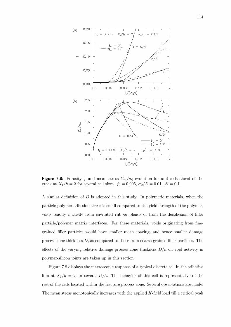
114
Figure 7.8: Porosity f and mean stress Σm/σ0 evolution for unit-cells ahead of thecrack at X1/h = 2 for several cell sizes. f0 = 0.005, σ0/E = 0.01, N = 0.1.
A similar definition of D is adopted in this study. In polymeric materials, when the
particle-polymer adhesion stress is small compared to the yield strength of the polymer,
voids readily nucleate from cavitated rubber blends or from the decohesion of filler
particle/polymer matrix interfaces. For these materials, voids originating from fine-
grained filler particles would have smaller mean spacing, and hence smaller damage
process zone thickness D, as compared to those from coarse-grained filler particles. The
effects of the varying relative damage process zone thickness D/h on void activity in
polymer-silicon joints are taken up in this section.
Figure 7.8 displays the macroscopic response of a typical discrete cell in the adhesive
film at X1/h = 2 for several D/h. The behavior of this cell is representative of the
rest of the cells located within the fracture process zone. Several observations are made.
The mean stress monotonically increases with the applied K-field load till a critical peak

115
stress is reached (Fig. 7.8b). This peak Σm value corresponds to the onset of rapid void
growth (Fig. 7.8a). Beyond this point, Σm decreases as the stress elevation is unable
to compensate for the softening from void growth. In the early loading stages when no
void growth occurs, the mean stress evolution curves for all three cell sizes are identical.
At higher loadings after the initiation of void growth, the stress evolution curves begin
to deviate, with the smaller cell sizes reaching unstable void growth at lower applied
loads.
These trends suggest that adhesives with smaller D/h would undergo rapid unstable
void growth at much lower critical loading than for adhesives with larger D/h. Observe
the smaller J/(σ0h) required for cells with smaller D/h to reach the critical peak stress
level. As D becomes small compared to h, enhanced interactions between the closely
spaced voids could favor accelerated void growth, leading to brittle-like adhesive failure.
By contrast, as D becomes of comparable size to h, isolated void activity is more or less
observed in the adhesive, and the void growth rate is reduced.
Experimental studies of the effects of damage process zone thickness on the toughness
of rubber modified epoxies were performed by Du et al. (1998). They showed that the
decrease in the thickness of the damage process zone D, from 200 μm for 10- and 15-phr
(parts per 100 parts of rubber by weight) rubber modified epoxies to about 150 μm for
the 20- and 25-phr rubber modified epoxies, resulted in a significant drop in steady-state
fracture toughness. The reduction in fracture toughness levels with decreasing D/h can
also be anticipated from the earlier onset of voiding and the accelerated void growth rate
shown in Fig. 7.8. A detailed discussion on the effects of D/h on the fracture toughness
trend will follow in the next section.
7.6 Void coalescence and fracture toughness trend
In order to model final material separation, a criterion for void coalescence is required.
Crack growth studies have traditionally assumed that final material failure occurs at
a constant critical porosity level fc (e.g. Xia and Shih, 1995a). The validity of this
attractive but oversimplified concept has been assessed by Pardoen and Hutchinson
(2000). It has been shown that fc is not a material constant, but is dependent on the
initial porosity and stress triaxiality, among other parameters.

116
Figure 7.9: Crack growth resistance curves for (a) several cell sizes with f0 = 0.01 andf0 = 0.05; (b) f0 = 0.05 with ψα = ψβ = 0
◦ and 10◦. σ0/E = 0.01, N = 0.1.
Of the two possible damage mechanisms which have been identified in Section 7.4,
only the contiguous damage zone mechanism, involving void by void crack advance, is
amenable to fracture resistance analysis. The initial adhesive porosity associated with
this voiding pattern for σ0/E = 0.01 ranges from 0.01 ≤ f0 ≤ 0.05. Along the crackplane, each cell element in succession experiences stress elevation due to strain hardening,
followed by material softening from void growth. A typical mean stress versus load
history profile at the cell element level was earlier depicted in Fig. 7.8b. One can see that
the peak mean stress level demarcates the critical point beyond which the cell rapidly
loses its stress carrying capacity due to rapid void growth and coalescence. Motivated
by this observation, the void volume fraction at the peak mean stress level, denoted by
fc, is operationally defined as the criterion for crack growth. Based on this criterion,
the cell with fc is taken as the effective location of the crack-tip. Initial investigations in
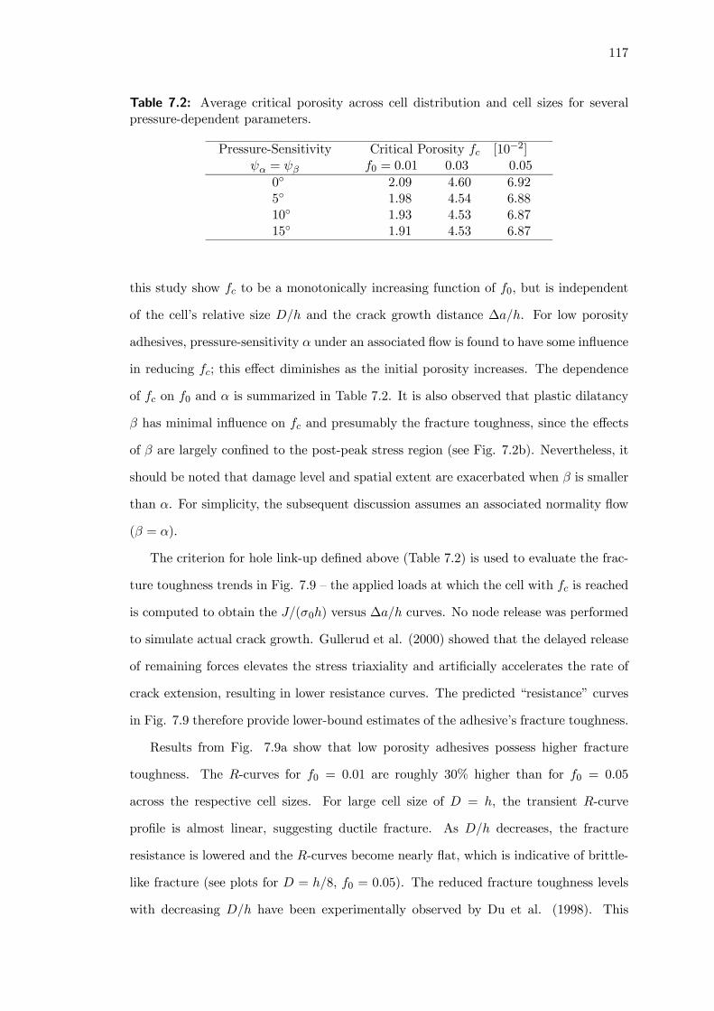
117
Table 7.2: Average critical porosity across cell distribution and cell sizes for severalpressure-dependent parameters.
Pressure-Sensitivityψα = ψβ
Critical Porosity fc [10−2]f0 = 0.01 0.03 0.05
0◦
5◦
10◦
15◦
2.09 4.60 6.921.98 4.54 6.881.93 4.53 6.871.91 4.53 6.87
this study show fc to be a monotonically increasing function of f0, but is independent
of the cell’s relative size D/h and the crack growth distance ∆a/h. For low porosity
adhesives, pressure-sensitivity α under an associated flow is found to have some influence
in reducing fc; this effect diminishes as the initial porosity increases. The dependence
of fc on f0 and α is summarized in Table 7.2. It is also observed that plastic dilatancy
β has minimal influence on fc and presumably the fracture toughness, since the effects
of β are largely confined to the post-peak stress region (see Fig. 7.2b). Nevertheless, it
should be noted that damage level and spatial extent are exacerbated when β is smaller
than α. For simplicity, the subsequent discussion assumes an associated normality flow
(β = α).
The criterion for hole link-up defined above (Table 7.2) is used to evaluate the frac-
ture toughness trends in Fig. 7.9 — the applied loads at which the cell with fc is reached
is computed to obtain the J/(σ0h) versus ∆a/h curves. No node release was performed
to simulate actual crack growth. Gullerud et al. (2000) showed that the delayed release
of remaining forces elevates the stress triaxiality and artificially accelerates the rate of
crack extension, resulting in lower resistance curves. The predicted “resistance” curves
in Fig. 7.9 therefore provide lower-bound estimates of the adhesive’s fracture toughness.
Results from Fig. 7.9a show that low porosity adhesives possess higher fracture
toughness. The R-curves for f0 = 0.01 are roughly 30% higher than for f0 = 0.05
across the respective cell sizes. For large cell size of D = h, the transient R-curve
profile is almost linear, suggesting ductile fracture. As D/h decreases, the fracture
resistance is lowered and the R-curves become nearly flat, which is indicative of brittle-
like fracture (see plots for D = h/8, f0 = 0.05). The reduced fracture toughness levels
with decreasing D/h have been experimentally observed by Du et al. (1998). This

118
Figure 7.10: Distribution of (a) porosity f and (b) mean stress Σm/σ0 ahead of thecrack for f0 = 0.01 at J/(σ0h) = 0.06 with several internal pressures, p/σ0 = 0, 0.5 and1.
suggests that increasing the spacing between void nucleating particles can bring about
significant improvements to the adhesive’s fracture properties.
Figure 7.9b compares the R-curves for f0 = 0.05 with ψα = ψβ = 0◦ and 10◦.
Observe that as ψα increases, the fracture toughness is correspondingly lowered. The
combination of high pressure-sensitivity and small cell size can lead to rapid failure.
7.7 Vapor pressure effects on adhesive damage
The studies in Chapters 3—5 offer some evidence of vapor pressure assisted void growth
and coalescence as a key mechanism of popcorn cracking in IC packages. The axisymmet-
ric unit-cell study in Chapter 6 suggests that the damaging effects of internal pressure
can be less severe for a pressure-sensitive material.
Figure 7.10 shows the porosity and mean stress distribution plots for f0 = 0.01 with
constant vapor pressure levels of p/σ0 = 0, 0.5 and 1. Observe that vapor pressure

119
Figure 7.11: Distribution of (a) porosity f and (b) mean stress Σm/σ0 ahead of thecrack for f0 = 0.05 at J/(σ0h) = 0.03 with several internal pressures, p/σ0 = 0, 0.5 and1.
accelerates voiding activity as well as growth of the damage zone. At J/(σ0h) = 0.06,
an increase in p/σ0 from 0 to 1 raises the peak f by about four times. The stress carrying
capacity of the adhesive film is also lowered, with an extended damage zone spanning a
distance > 10h from the crack-tip.
Results for high initial porosity adhesives of f0 = 0.05 are shown in Fig. 7.11.
Observe that voiding in the thin film adhesive becomes very intense under increasing
internal pressure. The corresponding mean stress distribution plots display a nearly
flat mean stress profile, suggesting large-scale adhesive damage with brittle-like failure
characteristics. This rapid, unstable void growth in the face of moisture-induced internal
pressure can explain the catastrophic nature of popcorn cracking observed by Fukuzawa
et al. (1985) and Gallo and Munamarty (1995).
The effects of adhesive pressure-sensitivity, ψα, under an associated flow rule, are

120
next examined (dashed curves in Figs. 7.10 and 7.11). For low p/σ0, pressure-sensitivity
(ψα = 10◦) lowers the stress carrying capacity of the adhesive, and intensifies adhesive
damage. Comparing the plots for ψα = 0◦ and ψα = 10◦ under high levels of vapor
pressure (i.e. p/σ0 = 1 in Figs. 7.10 and 7.11), it is observed that increasing adhesive
pressure-sensitivity can reduce the damaging effects of vapor pressure. This deduction
can also be anticipated from the analytical formulation for a fully-plastic matrix in
Appendix C.
7.8 Concluding remarks
A numerical study detailing the effects of pressure-sensitivity and plastic dilatancy on
void growth and coalescence in a constrained adhesive film has been performed. Damage
in the film was modeled by a row of unit-cells, each of dimensions D by D, containing
discrete voids lying on the crack plane ahead of a crack. The failure mechanisms exhib-
ited include the multiple damage zone and the contiguous damage zone mechanisms for
low and high initial porosity adhesives respectively. These failure mechanisms are differ-
ent from those observed by Tvergaard and Hutchinson (2002) for cracks in homogeneous
materials.
The study also shows that increasing pressure-sensitivity significantly intensifies the
level of damage as well as increases the spatial extent of damage in the adhesive by several
folds. Initiation of voiding for pressure-sensitive adhesives also occurs at lower external
loading, but with a smaller rate of void expansion as compared to pressure-insensitive
adhesives. Pressure-sensitivity effects are even greater for a non-associated flow rule,
β < α — the level and spatial extent of damage increases with the deviation from an
associated flow rule, |β − α|. This limited study suggests that damage in polymers aswell as load bearing predictions based on an associated flow rule could be conservative.
Under moisture-induced internal pressure, large-scale adhesive damage is observed. The
effects of vapor pressure, however, are less severe for a pressure-sensitive adhesive.
The number of voids in the adhesive was systematically varied for a fixed film thick-
ness h to study the influence of the cell’s relative sizeD/h (related to the relative damage
process zone thickness). A reduction in D/h dramatically accelerates both the spatial
extent of adhesive damage and the voiding intensity. This stems from the increased

121
void interaction associated with smaller void spacing. Adopting a failure criterion for
crack growth based on a critical porosity, it was further shown that the combination
of increasing pressure-sensitivity and reducing D/h could significantly lower the joint
toughness, promoting brittle-like fracture. These findings are consistent with experi-
mental observations of Du et al. (1998).
122
CHAPTER 8
PRESSURE-SENSITIVE DUCTILE LAYERS: 3D
MODELS OF EXTENSIVE DAMAGE
Research scope
Micromechanical analyses in Chapter 7 adopted cylindrical voids to describe the ductilefracture process ahead of a crack. Real voids and microstructures in actual polymericmaterials are three-dimensional in nature. This chapter conducts a three-dimensionalstudy of the pressure-sensitivity and plastic dilatancy effects on void growth and coa-lescence in polymeric adhesive joints.
Main findings
Pressure-sensitivity dramatically increases the extent of adhesive damage and reducesthe toughness of the joint. When coupled with high initial porosity, failure of pressure-sensitive adhesives involve synergistic cooperative void growth. The study also affirmsthe necessity for the three-dimensional modeling of high yield strain materials.
Extracts from this chapter can be found in Journal Paper [8] and Conference Paper[8].
8.1 Introduction
In Chapter 7, a single row of discrete cylindrical voids was modeled ahead of a crack
to study the mechanisms of void growth and coalescence in pressure-sensitive polymeric
layers. This chapter extends the previous work by explicitly modeling initially spher-
ical voids in a three-dimensional configuration. The three-dimensional analysis would
provide more realistic failure predictions since the real voids and microstructures in
actual polymeric materials are three-dimensional in nature. In addition to the pressure-
sensitivity and relative cell size effects on void growth and damage zone extension, the
shape evolution of the voids and intervoid ligament reduction are examined in detail.
These aspects of ductile fracture can shed light on the interaction and coalescence of
voids ahead of the crack front.
Previous studies have shown that the onset of coalescence is associated with distinc-
tive changes in the void shape and intervoid ligament distance. Koplik and Needleman
(1988) performed axisymmetric unit cell model computations and showed that material

123
failure occurs when localization of plastic flow takes place in the ligament, resulting in
a transition to uniaxial straining. Pardoen and Hutchinson (2000) observed a change in
the void shape evolution upon the onset of coalescence, where radial growth becomes
significantly larger than axial growth. Bandstra et al. (2004) noted that large, elon-
gated voids formed during the deformation could induce strong void interactions over
an extended regime within the microstructure. Focusing on cracked homogeneous ma-
terials, Tvergaard and Hutchinson (2002), Kim et al. (2003) and Cheng and Guo (2006)
also revealed that the highly inhomogeneous deformation and multiple void interaction
effects could result in the formation of oblate voids ahead of the crack.
The outline of this chapter is as follows: Section 8.2 describes the discrete void imple-
mentation in the three-dimensional small-scale yielding configuration. Section 8.3 com-
pares the predictions of this three-dimensional model, against both the two-dimensional
study in Chapter 7, and the computational cell element model adopted in Chapters 4
and 5. In Section 8.4, the effects of pressure-sensitivity and relative cell size on the
porosity/shape evolution of the voids and ligament reduction ahead of the crack are
examined. The contributions of pressure-sensitivity and plastic dilatancy to the process
zone extension and fracture toughness trend are subsequently studied in Section 8.5.
Experimental observations show that the plastic deformation of amorphous polymers
exhibits intrinsic softening followed by progressive rehardening at large strains (Van
Melick et al., 2003). In Section 8.6, the softening-rehardening yield characteristics of
pressure-sensitive polymeric layers are briefly discussed. A short summary in Section
8.7 concludes this chapter.
8.2 Problem formulation
Finite element analysis is carried out to study the failure of a cracked ductile polymeric
layer of thickness h, bonded between two identical substrates, subjected to remote mode I
loading. The substrates are taken to be elastic, with Young’s modulus, Es, and Poisson’s
ratio, νs. The elastic properties of the layer are designated by E and ν; the plastic
behavior is described by a pressure-dependent yield criterion under a non-associated
flow rule (Eqs. (2.4) — (2.9) in Chapter 2). This pressure-dependent model is included
in the material library in ABAQUS Version 6.3.1 (2002).
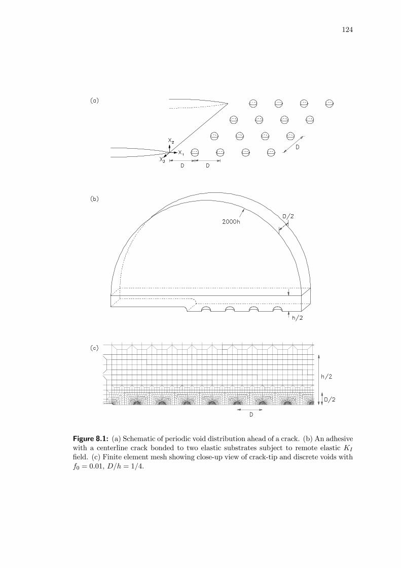
124
Figure 8.1: (a) Schematic of periodic void distribution ahead of a crack. (b) An adhesivewith a centerline crack bonded to two elastic substrates subject to remote elastic KI
field. (c) Finite element mesh showing close-up view of crack-tip and discrete voids withf0 = 0.01, D/h = 1/4.

125
In Chapter 7, void growth in the polymeric layer was confined to a single row of
discrete, initially circular cylindrical voids deployed directly ahead of a crack. In this
chapter, discrete initially spherical voids are periodically distributed along the crack
plane, with void spacing D by D in the X1- and X3-coordinate directions (see Fig. 8.1a).
By taking advantage of symmetry along the crack plane, only one-half of the geometry
needs to be modeled. In addition, the deformation along the thickness direction of the
specimen is assumed to be periodically symmetric. As such, only one-half of the void
spacing distance D/2 is modeled through the thickness, with displacement component
u3 = 0 along the planes for X3 = 0 and X3 = −D/2. This geometry is shown in Fig.
8.1b.
Each unit-cell is of initial dimensions D ×D ×D, and contains a discrete spherical
void of initial radius R0. The initial void volume fraction is defined by f0 =43πR
30/D
3.
The overall stress of each unit-cell is computed from
Σij =1
V
ZVσijdv (8.1)
where σij represents the local Cauchy stress within a voided cell, and V is the cell
volume in the current deformed configuration. The macroscopic mean stress is given
by Σm = Σkk/3, with the effective stress defined as Σe =q
32SijSij , where Sij is the
deviatoric part of Σij . The current void volume fraction in each unit-cell is calculated
from f = Vf/V where Vf represents the current void volume obtained by numerical
integration.
The boundary layer configuration is depicted in Fig. 8.1b. Along the remote circular
boundary of radius 2000h, the elastic asymptotic (in-plane) mode I displacement field
is applied (see Eq. (3.5)). The relationship between the mode I stress-intensity factor
KI and the energy release rate G (and hence the J-integral) is given by (3.6).
Figure 8.1c displays the close-up view of the finite element mesh near the crack-tip
for f0 = 0.01, D/h = 1/4. In this example mesh, a total of 47 discrete voids is used.
The additional length scale h for the adhesive layer infers the importance of the cell’s
relative size D/h. For D/h = 1 and 1/2, the number of voids introduced are 11 and
23 respectively. The mesh contains 8-node linear brick elements. The computations
are performed within the finite strain setting using the general-purpose finite element
program ABAQUS Version 6.3.1 (2002).

126
Figure 8.2: Comparison of two- and three-dimensional discrete voids for porosity dis-tribution f ahead of crack (X2 = 0) in pressure-insensitive layers (α = β = 0).σ0/E = 0.01, N = 0.1, D/h = 1/4, (a) f0 = 0.01; (b) f0 = 0.05.
In this chapter, the properties of the ductile layer are specified by the parameters
σ0/E = 0.01, and ν = 0.4. The elastic modulus mismatch between the layer and the
substrate is taken as Es/E = 10 with νs = 0.3. Unless otherwise stated, a moderate
hardening exponent of N = 0.1 is assumed. These values are representative of polymer-
silicon joints in IC packages. Initial void volume fractions of f0 = 1% and 5% are
also assumed, based on the estimated porosity levels for the die-attach and molding
compound in PBGA packages from available moisture analysis.
8.3 Model comparison
Previous studies have demonstrated that the use of spherical voids as opposed to cylin-
drical voids could result in vastly different failure responses. For example, Hom and
McMeeking (1989) focused on the interaction between a growing void and the crack-tip,

127
and demonstrated that initially cylindrical voids could grow up to five times faster than
the rate of spherical voids. Kim et al. (2003) and Gao et al. (2005) showed that the
fracture toughness levels for a crack in a homogeneous elastic-plastic solid containing
an array of spherical voids were consistently higher than the predictions of Tvergaard
and Hutchinson (2002) who adopted cylindrical voids. In the same spirit, damage pre-
dictions of the current three-dimensional model containing initially spherical voids are
first compared against the two-dimensional cylindrical void model previously employed
in Chapter 7. Hereafter, the former and latter are referred to as the “3D model” and
“2D model” respectively.
The approach used in this chapter can be traced to the early works of Xia and Shih
(1995a). They proposed that the fracture process zone can be idealized by placing a
single row of void-containing cells ahead of the crack-tip (see Chapter 2.3.2). The pro-
gressive damage of these cell elements is governed by the Gurson constitutive model
(Gurson, 1977). The current study attempts to replicate the exact void growth behav-
ior using discrete voids. To critically assess the discrete void model in this chapter,
predictions of the current 3D model are also compared against the computational cell
element approach of Xia and Shih (1995a).
For comparison purposes, a fixed cell size of D = h/4 is assumed in this section,
with the adhesives modeled as elastic-plastic materials, obeying an associated flow rule,
i.e. α = β = 0.
8.3.1 Three-dimensional versus two-dimensional discrete voids
Figure 8.2 displays the porosity evolution ahead of the crack for the adhesive joint
with initial porosity levels of f0 = 0.01 and 0.05. Comparing the plots for the 2D and
3D models at the same J/(σ0h), it is noted that the porosity distribution curves for
the former are consistently higher than those for the latter. This suggests that the
2D model in Chapter 7 over-estimates the actual damage levels ahead of the crack.
Higher constraint levels are experienced by these cylindrical voids since the deformation
is implicitly confined to the in-plane direction. As a result, the higher hydrostatic stress
levels in the layer activate unstable voiding, in which the stored elastic energy drives the
rapid plastic expansion of the cylindrical voids. By contrast, spherical voids can grow

128
in the out-of-plane direction, and hence are subjected to lower constraint/hydrostatic
stress levels. This could partly explain the slower void growth rates for the 3D model.
At this juncture, it is helpful to recall the radial equilibrium solutions for spherical
and cylindrical void growth in elastic-plastic solids. See Eqs. (B.7) and (C.11) in
Appendices B and C respectively. From these analytical solutions, it can be inferred
that the critical stress level required to trigger unstable void growth for cylindrical voids
is much lower than that for spherical voids. This could contribute to the higher void
growth rates for cylindrical voids observed in Fig. 8.2.
While large quantitative differences in the damage predictions are observed between
the 2D and 3D models, it is noted that the failure mechanisms exhibited by both models
are qualitatively similar, i.e. “multiple damage zone” and “contiguous damage zone”
mechanisms for low and high initial porosity adhesives respectively. The former mech-
anism can be attributed to the built-up of high stress triaxiality some distances ahead
of the crack front (Varias et al., 1991), while the latter is a result of the synergistic
cooperative growth of voids along the crack plane. These failure mechanisms have been
experimentally observed in constrained epoxy adhesives (Chai, 1993).
8.3.2 Discrete voids versus computational cell elements
Predictions of the three-dimensional discrete void model are next compared against the
computational cell element model proposed by Xia and Shih (1995a). For the latter,
a single row of uniformly-sized computational cell elements is deployed ahead of the
crack in place of the discrete voids shown in Fig. 8.1c. Each cell element, the size of
D/2×D/2, contains a void of initial volume fraction f0. The behavior of each cell element
is governed by the Gurson constitutive relation (Gurson, 1977), which was derived from
an approximate solution to axisymmetric void growth in a fully-plastic matrix. The flow
potential is obtained by setting p = 0 and q1 = q2 = 1 in (2.1). The properties for the
ductile layer in both models are specified by σ0/E = 0.01, ν = 0.4, and N = 0.
Results show that the computational cells consistently under-predicts damage levels
ahead of the crack. For f0 = 0.01 at J/(σ0h) = 0.066 in Fig. 8.3a, the actual peak
porosity level of the real hole is 60% higher and the damage extent is nearly two-fold
longer vis-à-vis the computational cell. Similar observations are made for higher initial

129
Figure 8.3: Comparison of three-dimensional discrete voids and computational cellelements for the porosity distribution f ahead of crack (X2 = 0) in pressure-insensitivelayers (α = β = 0). σ0/E = 0.01, N = 0, D/h = 1/4, (a) f0 = 0.01; (b) f0 = 0.05.
porosity levels of f0 = 0.05 in Fig. 8.3b. It should be noted, however, that both
the discrete void and computational cell element models exhibit similar mechanisms of
failure for low and high initial porosity adhesives.
The lower damage predictions of the cell element model in Fig. 8.3 suggest that the
Gurson material is stiffer than the actual material. The effect is exacerbated for high
yield strain materials. This is expected since the elastic contribution to void growth
was neglected by the Gurson model. To exemplify the above, a model comparison is
performed in Fig. 8.4 for low yield strain adhesives of σ0/E = 0.002, which is repre-
sentative of metal-ceramic joints. Observe that the damage predictions of the 2D, 3D,
and cell element models are in good agreement. This shows that for low yield strain
materials, e.g. metals, both the 2D and cell element models can well describe actual
3D hole growth. By contrast for high yield strain polymers, which is the subject of this
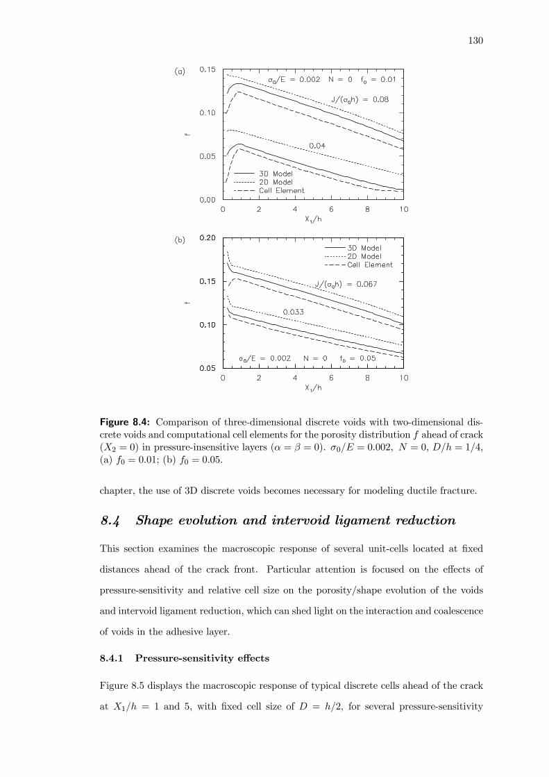
130
Figure 8.4: Comparison of three-dimensional discrete voids with two-dimensional dis-crete voids and computational cell elements for the porosity distribution f ahead of crack(X2 = 0) in pressure-insensitive layers (α = β = 0). σ0/E = 0.002, N = 0, D/h = 1/4,(a) f0 = 0.01; (b) f0 = 0.05.
chapter, the use of 3D discrete voids becomes necessary for modeling ductile fracture.
8.4 Shape evolution and intervoid ligament reduction
This section examines the macroscopic response of several unit-cells located at fixed
distances ahead of the crack front. Particular attention is focused on the effects of
pressure-sensitivity and relative cell size on the porosity/shape evolution of the voids
and intervoid ligament reduction, which can shed light on the interaction and coalescence
of voids in the adhesive layer.
8.4.1 Pressure-sensitivity effects
Figure 8.5 displays the macroscopic response of typical discrete cells ahead of the crack
at X1/h = 1 and 5, with fixed cell size of D = h/2, for several pressure-sensitivity
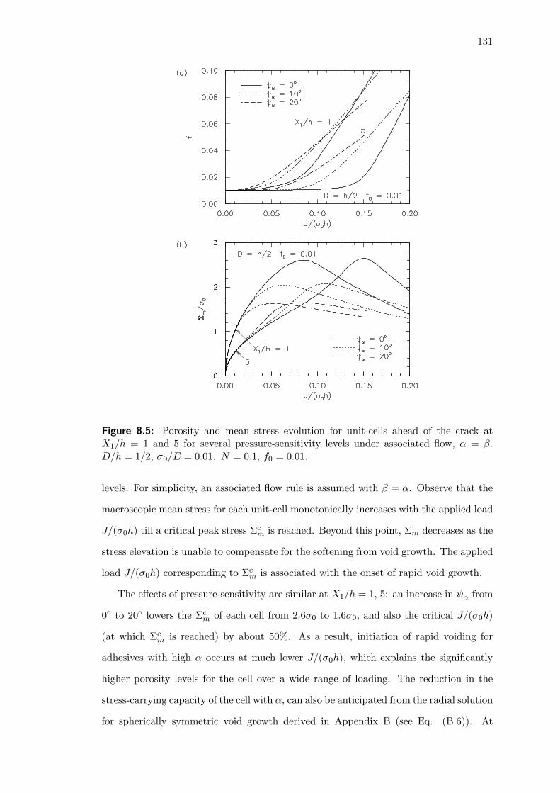
131
Figure 8.5: Porosity and mean stress evolution for unit-cells ahead of the crack atX1/h = 1 and 5 for several pressure-sensitivity levels under associated flow, α = β.D/h = 1/2, σ0/E = 0.01, N = 0.1, f0 = 0.01.
levels. For simplicity, an associated flow rule is assumed with β = α. Observe that the
macroscopic mean stress for each unit-cell monotonically increases with the applied load
J/(σ0h) till a critical peak stress Σcm is reached. Beyond this point, Σm decreases as the
stress elevation is unable to compensate for the softening from void growth. The applied
load J/(σ0h) corresponding to Σcm is associated with the onset of rapid void growth.
The effects of pressure-sensitivity are similar at X1/h = 1, 5: an increase in ψα from
0◦ to 20◦ lowers the Σcm of each cell from 2.6σ0 to 1.6σ0, and also the critical J/(σ0h)
(at which Σcm is reached) by about 50%. As a result, initiation of rapid voiding for
adhesives with high α occurs at much lower J/(σ0h), which explains the significantly
higher porosity levels for the cell over a wide range of loading. The reduction in the
stress-carrying capacity of the cell with α, can also be anticipated from the radial solution
for spherically symmetric void growth derived in Appendix B (see Eq. (B.6)). At

132
Figure 8.6: Void shape history at X1/h = 1 and 5 and ligament reduction historylocated to the right of the corresponding voids for several pressure-sensitivity levelsunder associated flow, α = β. D/h = 1/2, σ0/E = 0.01, N = 0.1, f0 = 0.01.
sufficiently high loads, however, the higher mean stresses and hence constraint levels for
the cell with low α result in higher void growth rates.
The shape evolution of the voids are next examined in Fig. 8.6a. The computations
show that the voids remain nearly spherical in the X1-X3 plane throughout the defor-
mation. As such, attention is directed towards the shape evolution of the voids in the
X1-X2 plane defined by the void aspect ratio b/a, where a and b represent the deformed
semi-axes of the void in the X1 and X2 directions respectively. The void is considered
to be oblate when b/a < 1, and prolate when b/a > 1.
Results show that the voids remain nearly spherical during the initial loading before
Σcm is reached. Beyond this point, rapid unstable voiding occurs resulting in a sudden
drop in b/a. As the loading progresses, the oblacity of the voids reaches a maximum
133
(corresponding to minimum b/a). Subsequent deformation increases b/a. Close exam-
ination of the effects of pressure-sensitivity shows that increasing ψα(= ψβ) increases
the oblacity of the voids at low to moderately high load levels, which is the regime of
interest. Observe that for X1/h = 5, an increase in ψα from 0◦ to 20◦ at J/(σ0h) = 0.14
reduces b/a by nearly 15%. At very high loads, voids in pressure-sensitive adhesives be-
come less oblate as compared to their pressure-insensitive counterparts. It is also noted
that the maximum oblacity of the voids decreases with ψα.
Figure 8.6b displays the intervoid ligament reduction ratio χ/χ0 versus loading his-
tory for the ligaments located to the right of the voids at X1/h = 1 and 5 — these curves
are labeled byX1/h = 1 and 5 respectively. The symbols χ(= D−2a) and χ0(= D−2R0)represent the current and initial lengths of the ligament between two neighboring voids
along the X1-direction at X2 = X3 = 0. Results show that accelerated ligament reduc-
tion commences at the onset of unstable voiding, and the intervoid separation distance
rapidly approaches zero as the deformation progresses. Coalescence of voids typically
commences before the ligament completely necks down to zero. For example, Tvergaard
and Hutchinson (2002) assumed that the onset of coalescence occurs when the intervoid
ligament distance has been reduced to the ratio χ/χ0 = 0.33 or 0.5. Molecular dynamic
simulations by Seppälä et al. (2004) also suggested that the critical intervoid ligament
distance is approximately one void radius, and is independent of the strain rate or the
starting separation distance.
Focusing on the effects of pressure-sensitivity, it is observed that an increase in
ψα(= ψβ) accelerates the reduction in χ/χ0 at low to moderately high loads. This
trend is suggestive of increased void interaction effects, and is closely related to the
increased oblacity of the voids shown in Fig. 8.6a. At larger J/(σ0h), adhesives with
low ψα experience greater reduction in χ/χ0. Clearly, whether ψα increases or reduces
the severity of internal necking in the adhesive is loading dependent.
8.4.2 Relative cell size effects
Xia and Shih (1995a) defined the cell size D as the thickness of the fracture process
zone, and correlated it with the mean spacing between voids. A similar definition of
D is adopted in this study. In polymeric materials, the decohesion of fine-grained or

134
Figure 8.7: Porosity and mean stress evolution for unit-cell ahead of the crack atX1/h = 1 for several relative cell sizes under associated flow, α = β. σ0/E = 0.01,N = 0.1, f0 = 0.01.
coarse-grained filler particles will influence the mean spacing between voids, and hence
the process zone thickness D. For plastic encapsulated packages, a typical die attach
is about 40 μm thick, while the spacing between voids is on the order of microns. In
rubber-modified epoxies, the process zone thickness can become a fraction of the film
thickness, with D ranging from 140 μm to 300 μm (e.g. Du et al., 2000). For a tractable
study of the relative cell size effects, the range of D/h between 0.25 and 1 is adopted.
Figure 8.7 displays the macroscopic response of a typical discrete cell at X1/h = 1 in
the adhesive film for several D/h. The behavior of this cell is representative of the rest
of the cells located within the fracture process zone. For fixed ψα(= ψβ), observe that
reducing D/h accelerates adhesive failure through a two-prong process: (i) the onset of
rapid void growth occurs earlier, as seen from the slightly lower J/(σ0h) corresponding to
Σcm, and (ii) the void growth rate becomes significantly higher. Note that the growth rate

135
Figure 8.8: Void shape history at X1/h = 1 and ligament reduction history located tothe right of the corresponding void for several relative cell sizes under associated flow,α = β. σ0/E = 0.01, N = 0.1, f0 = 0.01.
of each void is altered by the stress field of the proximal void. As D becomes sufficiently
small compared to h, enhanced interactions between the closely-spaced voids could favor
accelerated void growth. By contrast, as D becomes of comparable size to h, isolated
void activity more or less occurs in the adhesive, and the void growth rate is reduced.
At this juncture, reference is made with the experimental investigations by Du et
al. (1998) on the process zone development in rubber-modified epoxies. They showed
that the decrease in the thickness of the damage process zone D, from 200 μm for
10- and 15-phr (parts per 100 parts of rubber by weight) rubber modified epoxies to
about 150 μm for the 20- and 25-phr rubber modified epoxies, resulted in a significant
drop in steady-state fracture toughness. The reduction in fracture toughness levels with
decreasing D/h can also be anticipated from the numerical results in Fig. 8.7.
Figure 8.8 examines the effects of D/h on the void shape evolution at X1/h = 1 and

136
intervoid ligament reduction located to the right of the corresponding void. Observe the
sharp increase in the oblacity of the voids, and the rapid reduction in the intervoid liga-
ment distance, with small increase in J/(σ0h) for D = h/4. By contrast for D = h, the
reduction in both b/a and χ/χ0 with J/(σ0h) becomes very gradual. This suggests that
increased void interactions associated with decreasing cell size significantly accelerates
the void growth and coalescence process.
8.5 Damage and fracture of pressure-sensitive adhesives
This section evaluates the contributions of pressure-sensitivity α and plastic dilatancy
β to the growth and coalescence of voids ahead of the crack in ductile adhesive joints.
The evolving damage distribution and extension of the process zone are first examined.
Following which, a coalescence criterion is proposed and the fracture toughness trends
are studied. For computational convenience, a fixed cell size of D = h/2 will be adopted
in the analyses to follow.
8.5.1 Damage evolution ahead of crack
Recall from Figs. 8.5 and 8.7 that the applied load J/(σ0h) at the peak mean stress
level for each unit-cell ahead of the crack corresponds to the onset of rapid void growth.
Herein, the distance from the crack-tip, to the location where the cell is experiencing
the maximum Σm at given J/(σ0h), is operationally defined as the physical extent of
the damage process zone L. This cell location is denoted by open circles in Fig. 8.9,
which shows the porosity distribution ahead of the crack under an associated flow rule.
Referring to Fig. 8.9a for f0 = 0.01, one notes that at fixed external loads of
J/(σ0h) = 0.07 and 0.12, void activity for ψα = 0◦ is limited to within X1 < 4h. At
high pressure-sensitivity levels of ψα = 20◦, voids both near and far away from the crack
grow rapidly, resulting in extended damage zones spanning distances as far as X1 > 8h
from the crack-tip (for J/(σ0h) = 0.12). Similar effects of ψα are observed for f0 = 0.05
in Fig. 8.9b.
The effects of pressure-sensitivity on the spatial extent of adhesive damage for f0 =
0.01 are summarized in Fig. 8.10a under both associated and non-associated flow rules.
Results show that increasing pressure-sensitivity from ψα = 0◦ to 20◦ at fixed J/(σ0h),
under an associated flow rule (ψβ = ψα), increases the process zone length by several

137
Figure 8.9: Distribution of porosity f ahead of crack (X2 = 0) for several pressure-sensitivity levels under associated flow, α = β. D/h = 1/2, σ0/E = 0.01, N = 0.1, (a)f0 = 0.01; (b) f0 = 0.05.
folds (solid curves). For example, at J/(σ0h) = 0.1, L increases from 2h to 4h as ψα
increases from 0◦ to 10◦, and eventually to 7h for ψα = 20◦. Under non-associated
flow¯ψβ − ψα
¯= 5◦, effects of pressure-sensitivity on the process zone length are even
greater (dotted curves). Referring to Fig. 6.3 in Chapter 6, one can attribute this
phenomenon to the slightly lower post-peak stress-carrying capacity associated with
increasing deviation from the associated flow rule¯ψβ − ψα
¯. From Eq. (B.5) in the
Appendix B, it can also be noted that increasing plastic dilatancy suppresses the void
growth rate, which could explain the shorter process zone length L with increasing β
in Fig. 8.10a. While plastic dilatancy effects are relatively small compared to pressure-
sensitivity effects, it nevertheless suggests that fracture and failure predictions based on
the associated flow rule (β = α) could be slightly non-conservative.
For comparison purposes, results from the 2D model, previously adopted in Chapter
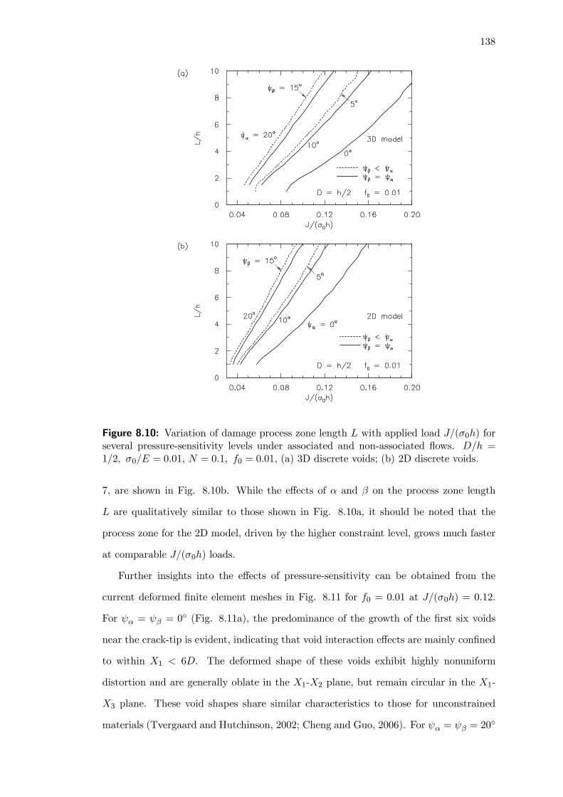
138
Figure 8.10: Variation of damage process zone length L with applied load J/(σ0h) forseveral pressure-sensitivity levels under associated and non-associated flows. D/h =1/2, σ0/E = 0.01, N = 0.1, f0 = 0.01, (a) 3D discrete voids; (b) 2D discrete voids.
7, are shown in Fig. 8.10b. While the effects of α and β on the process zone length
L are qualitatively similar to those shown in Fig. 8.10a, it should be noted that the
process zone for the 2D model, driven by the higher constraint level, grows much faster
at comparable J/(σ0h) loads.
Further insights into the effects of pressure-sensitivity can be obtained from the
current deformed finite element meshes in Fig. 8.11 for f0 = 0.01 at J/(σ0h) = 0.12.
For ψα = ψβ = 0◦ (Fig. 8.11a), the predominance of the growth of the first six voids
near the crack-tip is evident, indicating that void interaction effects are mainly confined
to within X1 < 6D. The deformed shape of these voids exhibit highly nonuniform
distortion and are generally oblate in the X1-X2 plane, but remain circular in the X1-
X3 plane. These void shapes share similar characteristics to those for unconstrained
materials (Tvergaard and Hutchinson, 2002; Cheng and Guo, 2006). For ψα = ψβ = 20◦

139
Figure 8.11: Deformed finite element meshes for pressure-sensitive layers under associ-ated flow, α = β, at J/(σ0h) = 0.12. D/h = 1/2, σ0/E = 0.01, N = 0.1, f0 = 0.01, (a)ψα = 0
◦; (b) ψα = 20◦.
(Fig. 8.11b), significant void growth occurs both near and far away from the crack-tip.
The shape of these voids are also highly oblate, indicating that void interaction effects
are prevalent throughout the adhesive. These findings suggest that increasing pressure-
sensitivity could result in a relatively flat fracture resistance curve.
At this point, reference is made with studies by Chowdhury and Narasimhan (2000a)
and Subramanya et al. (2006) on crack-tip fields in unvoided homogeneous materials
and constrained adhesive layers. They showed that pressure-sensitivity reduces the
near-tip stresses, which could retard the ductile fracture process. Focusing on voided
polymeric solids, however, the computations in Chapter 6 demonstrated that pressure-
sensitivity severely lowers the critical stress Σcm responsible for rapid void growth. The
present study on voided adhesive layers suggest that the reduction in Σcm with α is the
dominant influence. Consequently, lower critical J/(σ0h) loads are required to trigger
unstable voiding in adhesives with high pressure-sensitivity, which drives the formation
of extended damage zones.

140
8.5.2 Void coalescence and fracture toughness trends
In the context of material science, the fracture initiation toughness, JIC , involving the
coalescence of growing voids with the crack-tip, presents the most viable information
for indexing the fracture resistance of materials (Pardoen and Hutchinson, 2003). Crack
growth studies have traditionally assumed that the onset of void coalescence occurs at
a constant critical porosity level (Xia and Shih, 1995a) or at a fixed intervoid ligament
distance χc/χ0 (e.g. Horstemeyer et al., 2000; Seppälä et al., 2004).
Studies have shown that the critical porosity governing the onset of coalescence is
not a constant, but is dependent on the initial porosity and stress triaxiality, among
other parameters (Koplik and Needleman, 1988; Pardoen and Hutchinson, 2000). More-
over, the constant critical porosity criterion is not sensitive to the effects of void shape.
Referring to Figs. 8.6a and 8.8a, one can see that the voids become highly oblate with
the deformation. Results in Figs. 8.6b and 8.8b also show that the reduction in inter-
void ligament distance χ/χ0, and presumably χc/χ0, is dependent on both the loading
and the pressure-sensitivity index α. In view of this, a coalescence criterion which can
account for these parametric variations is proposed, and the fracture toughness trends
are studied.
Coalescence of a single cell. Before proceeding to study the fracture toughness
trends, a representative material volume consisting of a cubic cell of dimensionsD×D×Dwith a spherical void at its center is first considered. This representative material volume
is subjected to loading conditions similar to the cells in the small-scale yielding model.
Due to the overall geometrical symmetry, only one-eighth of the cell needs to be modeled.
The displacement condition u3 = 0 is imposed on the cell face normal to the X3-axis
to maintain consistency with the plane strain requirements for the crack analysis (see
insert in Fig. 8.12a). The plane strain unit cell is subjected to the principal stretches
λ1 and λ2 in the X1 and X2 directions, which specify the macroscopic principal strains
(E11, E22) and one effective strain measure Ee:
E11 = lnλ1, E22 = lnλ2, Ee =2
3
¡E211 −E11E22 +E222
¢1/2. (8.2)
The work-conjugate stresses to (E11, E22) are the macroscopic Cauchy stresses (Σ11,Σ22)
obtained from (8.1).

141
Specifically, the displacements
u1 = (λ1 − 1)X1, u2 = (λ2 − 1)X2, (8.3)
are incrementally imposed on the remote surfaces of X1 = D/2 and X2 = D/2 using
the procedure outlined by Smelser and Becker (1989) to maintain a constant stress ratio
Σ11/Σ22 throughout the entire loading history, with Σ11 ≤ Σ22. The properties of thecell are specified by σ0/E = 0.01, ν = 0.4 and N = 0.1, with f0 = 0.01.
The macroscopic effective stress-strain response of the discrete cell for several pressure-
sensitivity levels, under both associated and non-associated flow rules, is shown in Fig.
8.12a. Results presented are based on fixed stress ratio of Σ11/Σ22 = 0.5. The plots
display a common trend. The macroscopic effective stress initially increases with the
deformation until a peak Σe is reached. Beyond this point, Σe decreases since the rate
of strain hardening is unable to compensate for the higher rate of softening associated
with void growth. As the deformation progresses, a sudden drop in Σe occurs. Rapid
voiding takes place at this point, and the macroscopic deformation of the cell shifts to a
uniaxial strain state, i.e. E11 → 0. Following Koplik and Needleman (1988), the effective
strain at this point is termed as the critical effective strain Ec denoting the onset of void
coalescence. The f -value corresponding to Ec is referred to as the critical void volume
fraction, fc.
For a fixed dilation angle ψβ, one can see that an increase in ψα proportionally
decreases the macroscopic effective stress Σe. The corresponding effective strain at
coalescence Ec (indicated by the open circles) also decreases. Unlike the effects of α,
the influence of β is mainly confined to the post-peak stress region. Some effects of β
on Ec are also observed: for a fixed ψα, the maximum Ec occurs under associated flow
(ψα = ψβ), while the minimum Ec occurs under isochor plastic flow (ψβ = 0◦). This
reduction in Ec, when β tends to zero and incompressible flow is approached, suggests
a loss of ductility and could result in brittle-like failure of the material.
Fracture initiation toughness. A failure criterion, based on the occurrence of
void coalescence in the unit-cell model, is next proposed to study the fracture toughness
trends. At each loading instant J/(σ0h), the macroscopic stress ratio Σ11/Σ22 and the
current porosity f for the first cell deployed directly ahead of the crack can be calculated.

142
Figure 8.12: (a) Effective stress-strain plots for a plane strain unit-cell subjected toΣ11/Σ22 = 0.5 under associated and non-associated flows. σ0/E = 0.01, N = 0.1,f0 = 0.01. (b) Variation of JIC/(σ0h) with friction angle ψα for pressure-sensitive layersunder associated flow, α = β. D/h = 1/2, σ0/E = 0.01, N = 0.1, f0 = 0.05.
These values are compared against the variation of fc versus Σ11/Σ22 obtained from unit-
cell analyses similar to Fig. 8.12a. Fracture initiation is assumed when the porosity of
the first cell ahead of the crack front reaches the critical porosity fc predetermined by
unit-cell computations at the same stress ratios Σ11/Σ22. The applied J-value at this
instant denotes the fracture initiation toughness JIC/(σ0h).
Of the two possible damage mechanisms which have been identified in Section 8.3,
only the contiguous damage zone mechanism is amenable to fracture resistance analysis.
In view of this, attention is confined to high initial porosity adhesives, f0 = 0.05.
Figure 8.12b shows the variation of JIC/(σ0h) with pressure-sensitivity under an
associated flow rule. The discrete points in the figure represent the numerical values.
Observe that an increase in ψα from 0◦ to 20◦ reduces the fracture toughness levels by

143
nearly 60%. This trend can in-part be attributed to the sharp drop in stress-carrying
capacity of voided materials with pressure-sensitivity, as shown by the unit-cell calcula-
tions in Fig. 8.12a. In addition, the computations suggest that fc is a strong function
of ψα — a two-fold reduction of fc is noted as ψα increases from 0◦ to 20◦ (see the Ta-
ble inserted in Fig. 8.12b). Subramanya et al. (2006) also revealed that plastic strain
and notch blunting increases with pressure-sensitivity. The combination of these factors
could explain the increased susceptibility of pressure-sensitive adhesives to fracture.
This section concludes with a brief comment on the fracture resistance computations
in Chapter 7, where the void volume fraction at the peak mean stress Σcm of each cell
was defined as the criterion for fracture initiation. The use of such a failure criterion in
the present 3D model reveals much lower fracture toughness levels (0.04 < JIC/(σ0h) <
0.05) than in Fig. 8.12b. This inherent conservatism in the failure criterion is expected,
since actual coalescence of voids could occur beyond Σcm. As shown in Chapter 7, the
failure criterion based on Σcm is also only weakly dependent on ψα. The computations
in Fig. 8.12 suggest that actual dependence of fc on ψα is very pronounced.
8.6 Softening-rehardening yield characteristics
In the preceding sections, the polymeric adhesive is assumed to follow the power-law
plastic hardening relation. While this assumption can remain valid for certain polymers
which have undergone the process of mechanical rejuvenation to eliminate strain soften-
ing (see Fig. 12 of Van Melick et al., 2003), many polymers exhibit a true-stress/strain
curve exhibiting a maximum followed by a softening regime. As the deformation pro-
ceeds further, these polymers may exhibit rehardening (related to chain re-orientation).
In order to describe this yielding behavior, the following flow stress model is proposed
σ
σ0= 1 +
p
0
⎛⎜⎝ 1
1 + ξ³
p
0
´2 + p
η
⎞⎟⎠ (8.4)
where ξ mainly controls the maximum (i.e., the intrinsic yield point), and η describes
the softening-rehardening shape of the stress-strain curve. The reference yield strain 0
is related to the Young’s modulus E and the reference yield stress σ0 by 0 = σ0/E.
For reference, the uniaxial stress-strain curves for different η with ξ = 1 are included
in Fig. 8.13. Observe that beyond the reference yield point (σ = σ0), the material

144
Figure 8.13: Uniaxial true stress-strain response for the unvoided material: softening-rehardening description where rate of rehardening is controlled by the parametric settingof ξ = 1 and η = 10, 20, 40, 100 for σ0/E = 0.01, ν = 0.4.
exhibits strain hardening before reaching a maximum stress (intrinsic yield stress). The
difference between the reference and intrinsic yield stresses can be adjusted through the
parameter ξ. For simplicity, this study adopts ξ = 1 in what follows and focuses attention
on η. As shown in Fig. 8.13, variation of the parameter η can reproduce the possible
hardening softening-rehardening yield behaviors of polymers experimentally observed.
For comparison, Fig. 8.13 also includes the stress-strain curve for a power-law hardening
solid (N = 0.1) used in the earlier computations.
Some insights into the failure behavior of a softening-rehardening solid can be ob-
tained from the unit-cell study in Appendix D, which uses the above relation (8.4).
Results suggest that shear banding is the dominant failure mechanism under low stress
triaxiality. In highly constrained pressure-sensitive polymers (e.g. die-attach in IC
packages), internal necking becomes the dominant failure mode.
Figure 8.14 displays the effects of softening-rehardening on the porosity distribution
ahead of the crack under an associated flow (α = β). The intensity and spatial extent
of damage for a predominantly softening layer appears to be much greater than for one
with a strong rehardening response. For f0 = 0.01, ψα = 0◦, an increase in η from
20 to 100 increases both the peak porosity level and the process zone length by nearly
two-fold. For f0 = 0.05, ψα = 0◦, the peak porosity level and spatial extent of damage
increases by 1.3-fold and 1.4-fold respectively. These results suggest that softening
and rehardening are two counteracting factors which affect voiding and damage ahead

145
Figure 8.14: Distribution of porosity f ahead of crack (X2 = 0) for several η. D = h/2,σ0/E = 0.01, (a) f0 = 0.01; (b) f0 = 0.05.
of a crack. Softening tends to lower the stress-carrying capacity of the adhesive, in
turn accelerating void growth and coalescence. By contrast, strain rehardening seeks
to increase the work of separation, thereby suppressing both the intensity and spatial
extent of damage. Across all η, the spatial extent of damage becomes significantly larger
for ψα = 10◦.
The computational finite element meshes in the deformed configuration are depicted
in Fig. 8.15 for f0 = 0.01, at J/(σ0h) = 0.12. For the adhesive with η = 100, ψα = 0◦,
voids near the crack-tip are generally oblate. For η = 20, ψα = 0◦, the shape of the
voids evolve to have some prolate characteristics. The reduction in the oblacity of the
voids with decreasing η reduces the effects of void interaction within the layer. For
pressure-sensitive adhesives (ψα = 10◦), the deformed finite element meshes show the
tendency for voids both near and far away from the crack to grow; the shape of these

146
voids is predominantly oblate (see Figs. 8.15b and 8.15d).
8.7 Concluding remarks
In this chapter, an array of initially spherical voids is periodically distributed ahead of a
crack front in a three-dimensional configuration to study the mechanisms of void growth
and coalescence in pressure-sensitive polymeric layers. This 3D model is compared
against both the 2D cylindrical void model adopted in Chapter 7 and the computational
cell element model (Xia and Shih, 1995a) for a range of initial yield strains applicable
to metals and polymers. For adhesives with low yield strains, the damage predictions
of all three models are found to be in good agreement. For high yield strain adhesives,
however, significant quantitative differences among the three models are observed, which
affirms the necessity for the three-dimensional discrete void modeling of the problem at
hand.
The computations show that increasing pressure-sensitivity significantly intensifies
the damage level as well as increases its spatial extent several folds. The effects of
pressure-sensitivity become even greater as the deviation from an associated flow in-
creases. It is further shown that prior to void coalescence, pressure-sensitivity increases
the oblacity of the voids and reduces the intervoid ligament spacing within a wide range
of loading. The trend becomes less distinct under sufficiently large deformation. Reduc-
ing the relative fracture process zone thickness dramatically accelerates voiding activity
in the adhesive through increased void interaction — the voids become more oblate and
the intervoid ligament distances are rapidly reduced over large regions ahead of the
crack.
A failure criterion, based on the critical void porosity fc governing coalescence in
a representative material volume containing a discrete void, is employed to study the
fracture toughness trends. This criterion accounts for the parametric dependence of fc
on pressure-sensitivity, plastic dilatancy, void oblacity, and the loading ratio, amongst
others. The study demonstrates that pressure-sensitivity lowers both the stress-carrying
capacity of the material and fc, resulting in reduced toughness levels.
The study also shows that the softening-rehardening yield characteristics unique to
polymers have profound influence on void growth and coalescence in the constrained

147
adhesive. While strain softening tends to lower the stress-carrying capacity of the adhe-
sive, strain rehardening seeks to increase the work of separation, thereby lowering both
the intensity and spatial extent of damage. An increase in the rate of rehardening also
reduces the oblacity of the voids, which suppresses the void interaction effects.
This chapter concludes with a comment on the failure mechanisms in polymeric
materials and adhesives. Tvergaard and Hutchinson (2002) demonstrated that two
distinct mechanisms of failure for cracks in metals include the near-tip void growth and
coalescence, and the multiple void interaction mechanisms. Pressure-sensitive polymers,
however, are not governed by the former mechanism. As illustrated in this study, their
failure typically involves synergistic cooperative void growth. When coupled with large
initial porosity under highly constraint conditions, extensive damage zones are formed
ahead of the crack at low load levels. These damage patterns closely resemble the long
craze zones experimentally observed in amorphous polymers (see Fig. 2.4). This point
merits further study.

148
Figure 8.15: Deformed finite element meshes for polymeric layers with f0 = 0.01,D = h/2 at J/(σ0h) = 0.12. (a) η = 20, ψα = 0
◦; (b) η = 20, ψα = 10◦; (c) η = 100,
ψα = 0◦; (d) η = 100, ψα = 10
◦.

149
CHAPTER 9
SUMMARY OF CONCLUSIONS
This thesis focuses on the failure of polymeric adhesives, which are among some of the
more critical features found in multilayers and microelectronic packages. The research
scope is two-fold. The first part examines how variations in temperature and mois-
ture degrade mechanical properties of polymeric adhesives, and activate mechanisms
which in turn lead to cracking and interface delamination (Chapters 3—5). The second
part addresses the mechanisms of void growth and coalescence in ductile polymeric lay-
ers, taking into account the contributions of pressure-sensitivity and plastic dilatancy
(Chapters 6—8). The major findings are summarized as follows:
9.1 Mechanisms of failure in adhesive joints
Chapter 3 focuses on a ductile polymeric adhesive joining two elastic substrates pay-
ing particular attention to failure mechanisms which are precursors to popcorn cracking.
The study shows that ductile polymeric adhesives can fail by one of three damage mecha-
nisms: (i) contiguous damage zone emanating from the crack; (ii) multiple damage zones
forming at distances of several adhesive thicknesses ahead of the crack; and (iii) exten-
sive damage zone advancing along the adhesive/substrate interfaces. These numerically
simulated behaviors are consistent with experimentally observed failure mechanisms.
Adhesive with uniform initial porosity distribution
• The multiple damage zone mechanism is operative in low porosity adhesives, whilea rapidly advancing contiguous damage zone emanating from the main crack is
found in high porosity adhesives. The latter mechanism is also favored when the
voids are subjected to high vapor pressure. In low porosity adhesives, residual
stress enhances damage near the adhesive/substrate interface.
• Residual tensile stress and in particular vapor pressure accelerate voiding activityas well as the growth of the damage zone. This behavior offers an explanation for

150
the catastrophic nature of popcorn cracking.
• The fully porous adhesive model1 appears capable of simulating all three failuremechanisms noted above under a wide range of conditions. With one important
exception, the partially porous adhesive model2 correctly predicts voiding and
stress patterns in both low and high porosity adhesives. However it generally
overestimates the damage level ahead of the crack.
Adhesive with non-uniform initial porosity distribution
• Increasing amplitudes of non-uniformity in the initial porosity distribution ∆f0can result in the formation of multiple damage zones for both high and low mean
porosity adhesives.
• Under the influence of vapor pressure, increasing ∆f0 for low mean porosity ad-hesives promotes delamination near the film-substrate interfaces; for high mean
porosity adhesives, rapid voiding occurs simultaneously throughout the adhesive
resulting in large-scale adhesive damage.
9.2 Interfacial toughness of adhesive joints
Attention in this topic is directed at residual stress and vapor pressure effects on cracking
and toughness of joints formed by a ductile polymeric film and its elastic substrates.
Chapter 4 considers the parallel delamination of both film-substrate interfaces under
mode I loading, while Chapter 5 models the delamination of a single interface under
mixed mode loading.
• The analysis of crack growth during the cool down process (following solder re-flow) provides some estimates of the reduction in joint toughness related to film-
substrate CTE mismatch. These estimated joint toughness values are comparable
to those obtained from isothermal analyses where the CTE mismatch is treated
by introducing an initial residual stress.
• Residual tensile stresses in the film enhance brittle-like cracking characteristics,
bringing about severe reduction in toughness of the joint. The reduction in joint
1The fully porous adhesive model contains pre-existing voids distributed throughout the adhesive.2The partially porous adhesive model deploys a single row of void-containing cells ahead of the crack.

151
toughness can be compounded when the porosity of the material near the interface
is high.
• Vapor pressure has the most damaging effect on the interface integrity; high levelsof vapor pressure generated during reflow soldering accelerates voiding activity
leading to rapid crack propagation along the film-substrate interface. The interface
fracture toughness levels are comparable with available experimental data (Evans
et al., 1999; Gurumurthy et al., 2001).
• Across all mode mixity levels, vapor pressure effects dominate over residual stress.Under a strong mode II component, the adverse effects of vapor pressure can
cause a several-fold drop in the joint toughness. The latter denotes the likely state
of loading in IC packages since residual stress, resulting from the film-substrate
thermal mismatch, induces a predominantly mode II component.
9.3 Pressure-sensitivity and plastic dilatancy effects
This topic discusses how the distinctive characteristics of pressure-sensitivity, α, and
plastic dilatancy, β, can influence void growth, interaction, and subsequent coalescence
in polymeric materials and adhesives. Chapter 6 examines the macroscopic response of
porous pressure-sensitive dilatant materials subjected to physical stress states similar
to highly stressed regions ahead of a crack. Building on this knowledge, Chapters 7
and 8 focus on cracked pressure-sensitive dilatant adhesives subjected to remote mode
I loading.
Representative unit-cell
• Plastic dilatancy has some effect in raising the post-peak stress levels resultingin a larger work of separation, while an increase in pressure-sensitivity of the
material severely lowers its stress-carrying capacity. The mechanical strength of
the material is further weakened by an increasingly oblate void.
• In polymeric materials, the higher initial porosities and pressure-sensitivity levels(compared to metallic materials) can reduce the critical stress responsible for void
instability to levels comparable to the initial yield strength.

152
• The damaging effects of internal pressure can be less severe for a pressure-sensitivematerial. This observation is of importance in IC packages, since the porous
adhesives and molding compounds are often susceptible to moisture-induced void
growth.
• Microvoid interaction and pressure-sensitivity can work in concert in reducing thestress carrying capacity of the material. The former is responsible for the post-
peak stress drop while the latter controls the sustainable peak stress level. The
relative contribution of these parameters is loading dependent.
Pressure-sensitive ductile layers
• Increasing pressure-sensitivity significantly intensifies the level of damage as wellas increases the spatial extent of damage in the adhesive by several folds. Pressure-
sensitivity increases the oblacity of the voids and reduces the intervoid ligament
spacing within a wide range of loading. The fracture toughness levels are also
lowered, and the resistance curve exhibits a nearly flat profile, indicating brittle-
like adhesive failure.
• Pressure-sensitivity effects are even greater for a non-associated flow rule, β <
α. The level and spatial extent of damage increases with the deviation from an
associated flow rule, |β − α|, which suggests that damage in polymers as well asload bearing predictions based on an associated flow rule could be conservative.
• Reducing the fracture process zone thickness relative to the film thickness dramat-ically accelerates voiding activity in the adhesive through increased void interac-
tion, leading to reduced intervoid ligament distances and increased oblacity of the
voids over large distances ahead of the crack. These findings are consistent with
experimental observations of Du et al. (1998).
• Softening-rehardening yield characteristics unique to polymers have profound in-fluence on void growth and coalescence in the adhesive. While strain softening
tends to lower the stress-carrying capacity of the layer, strain rehardening seeks to
increase the work of separation, thereby suppressing both the intensity and spatial
extent of damage.

153
The studies show that the failure of polymers typically involve synergistic cooper-
ative void growth. When coupled with large initial porosity under highly constraint
conditions, extensive damage zones are formed ahead of the crack at low load levels.
These damage patterns closely resemble the long craze zones experimentally observed
in amorphous polymers (see Fig. 2.4).
9.4 Industrial implications
The problem of adhesive failure can be addressed from two perspectives: the first to
improve the design of adhesive joints to better withstand the demands of the environment
they are subjected to; the second to optimize the process conditions of these adhesive
joints.
This research shows that optimizing material design parameters, such as the selec-
tion of adhesives and substrates with similar thermal expansion coefficients, selection of
adhesives with low pressure-sensitive yielding, increasing the adhesive thickness, and in-
troducing filler particles with better particle-polymer adhesion strength in the adhesive
(thereby suppressing void formation), can help to improve joint toughness. However,
these efforts can be negated by high levels of vapor pressure, leading this research to
conclude that decreasing the exposure of adhesive joints to moisture-filled environment
is perhaps the most effective means of improving joint integrity.
9.5 Recommendations for future work
Real voids and microstructures in both metals and polymers are three-dimensional in
nature. In analyzing the failure behavior of these materials, numerical studies have
traditionally adopted constitutive models (e.g. Gurson model) or two-dimensional plane
strain models for computational convenience. In Chapter 8, the damage predictions of a
quasi-plane strain 3D discrete void model were compared against both the 2D cylindrical
void model and the computational cell element model for a range of initial yield strains
applicable to metals and polymers. The damage predictions of all three models were
found to be in good agreement for low yield strain materials. For high yield strain
materials, however, significant quantitative differences among the three models were
observed, which affirmed the necessity for the three-dimensional modeling of polymers.
A possible extension to the present work is the three-dimensional analysis of void

154
growth and interaction in a representative material volume containing two or more size
scales of voids (akin to the 2D analysis in Chapter 6.5). Such a study will not only
confirm the characteristic features elucidated upon by the 2D model, but can also be
instrumental in providing some qualitative understanding of the competition between
the damage mechanisms of shear banding and crazing.
As previously mentioned in Chapter 2.5, crazes are planar crack-like defects where
the two faces of the craze are bridged by thin fibrils. Upon application of stress, crazes
widen, leading to stretching of the bridging fibrils until eventual failure. For a numer-
ically tractable model for craze growth, the crazes ahead of a crack can be idealized
as an interconnected structure of periodically arranged pear-shaped voids bridged by a
number of cylindrical fibrils. These stiffer fibrils render the “craze” some stress-bearing
capabilities, giving rise to anisotropy in craze response to strain. At some experimen-
tally pre-determined stress level, node release can be performed to model the craze-
fibril breakdown which leads to subsequent crack propagation. Using this approach, a
better understanding on the effects of important material parameters, such as pressure-
sensitivity and plastic dilatancy, on craze widening and eventual failure can be obtained.
Experimental observations for adhesives in flip-chip packages subjected to high tem-
perature and humidity conditions have shown that die-attach failures could result from
the cracking of the die-attach medium itself, or from delamination of the film-substrate
interfaces, or both (Teh et al., 2005). This phenomenon was also observed by numerical
studies in Chapter 3 on constrained adhesive layers. The discrete void studies in Chap-
ters 7 and 8 assumed that the interface bond is strong and considered a centerline crack
in the ductile layer.
Another possible extension to the present work is in the three-dimensional study
of adhesive failures resulting from cracking along the adhesive-substrate interface. Of
particular interest are the effects of pressure-sensitivity and plastic dilatancy on the
damage evolution along the adhesive-substrate interface under mixed mode loading.
Chiang and Chai (1994) conducted finite element analyses of adhesively bonded fracture
specimens under pure mode II loading, and found the influence of pressure-sensitivity
on the plastic zone length and shear strain in the layer to be small. Similar conclusions
were reached by Chowdhury and Narasimhan (2000a). These studies however did not

155
consider the effects of pressure-sensitivity on void growth which could be significant.
More insights can be obtained from the proposed study.
156
REFERENCES
[1] Abaqus, 2002. Standard user’s manual, Vol. 1, Version 6.3.1. Hibbit, Karlsson andSorensen, RI, USA.
[2] Anderson, T.L., 1995. Fracture mechanics — fundamentals and applications. 2ndedition, CRC Press.
[3] Alpern, P., Dudek, R., Schmidt, R., Wicher, V., Tilgner, R., 2002. On the mode IIpopcorn effect in thin packages. IEEE Transactions on Components and PackagingTechnologies 25(1), 56-65.
[4] Ashby, M.F., Blunt, F.J., Bannister, M., 1989. Flow characteristics of highly con-strained metal wires. Acta Metallurgica 37, 1847-1857.
[5] Bandstra, J.P., Koss, D.A., Geltmacher, A., Everett, R.K., 2004. Modeling voidcoalescence during ductile fracture of a steel. Materials Science and EngineeringA 366, 269-281.
[6] Behan, P., Bevis, M., Hull, D., 1975. Fracture processes in polystyrene. Proceed-ings of the Royal Society London A343, 525-535.
[7] Benzerga, A.A., 2002. Micromechanics of coalescence in ductile fracture. Journalof the Mechanics and Physics of Solids 50, 1331-1362.
[8] Brown, H.R., 1991. Molecular interpretation of the toughness of glassy polymers.Macromolecules 24, 2752-2756.
[9] Buchwalter, S.L., Brofman, P.J., Feger, C., Gaynes, M.A., Lee,K. —W., Matienzo,L.J., Questad, D.L., 2005. Effects of mechanical stress and moisture on packaginginterfaces. IBM Journal of Research and Development 49, 663-675.
[10] Chai, H., 1993. Observation of deformation and damage at the tip of cracks inadhesive bonds loaded in shear and assessment of a criterion for fracture. Interna-tional Journal of Fracture 60, 311-326.
[11] Chai, H., 1988. Shear fracture. International Journal of Fracture 37, 137-159.
[12] Chai, H., 2003. Interfacial mixed-mode fracture of adhesive bonds undergoing largedeformation. International Journal of Solids and Structures 40, 6023-6042.
[13] Chang, W.J., Pan, J., 1997. Cavitation instabilities in plastics and rubber-modifiedplastics. International Journal of Fracture 88, 61-86.
[14] Chiang, M.Y.M., Chai, H., 1994. Plastic deformation analysis of cracked adhesivebonds loaded in shear. International Journal of Solids and Structures 31, 2477-2490.
[15] Cheng, L., Guo, T.F., 2003. Vapor pressure assisted void growth and cracking ofpolymeric adhesives and interfaces. Interface Science 11, 277-290.
[16] Cheng, L., Guo, T.F., 2006. Void interaction and coalescence inpolymeric materials. International Journal of Solids and Structures,doi:10.1016/j.ijsolstr.2006.08.007.

157
[17] Chowdhury, R.S., Narasimhan, R., 1995. Finite element simulations of ductilerupture in a constrained metal foil. Material Science and Engineering A191, 27-37.
[18] Chowdhury, R.S., Narasimhan, R., 2000a. A finite element analysis of station-ary crack-tip fields in a pressure sensitive constrained ductile layer. InternationalJournal of Solids and Structures 37, 3079-3100.
[19] Chowdhury, R.S., Narasimhan, R., 2000b. A finite element analysis of quasistaticcrack growth in a pressure sensitive constrained ductile layer. Engineering FractureMechanics 66, 551-571.
[20] Dalgleish, B.J., Lu, M.C., Evans, A.G., 1988. The strength of ceramics bondedwith metals. Acta Metallurgica 36, 2029-2035.
[21] Dalgleish, B.J., Trumble, K.P., Evans, A.G., 1989. The strength and fracture ofalumina bonded with aluminum alloys. Acta Metallurgica 37, 1923-1931.
[22] Dong, P., Pan, J., 1991. Elastic-plastic analysis of cracks in pressure sensitivematerials. International Journal of Solids and Structures 28, 1113-1127.
[23] Drucker, D.C., Prager, W., 1952. Soil mechanics and plastic analysis or limitdesign. Quarterly of Applied Mathematics 10, 157-165.
[24] Du, J., Thouless, M.D., Yee, A.F., 2000. Effects of rate on crack growth in arubber-modified epoxy. Acta Materialia 48, 3581-3592.
[25] Du, J., Thouless, M.D., Yee, A.F., 1998. Development of a process zone in rubber-modified epoxy polymers. International Journal of Fracture 92, 271-285.
[26] Dugdale, D.S., 1960. Yielding of steel sheets containing slits. Journal of the Me-chanics and Physics of Solids 8, 100-104.
[27] England, A.H., 1965. A crack between dissimilar media. Journal of Applied Me-chanics 32, 400-402.
[28] Estevez, R., Tijssens, M.G.A., van der Giessen, E., 2000. Modeling of the com-petition between shear yielding and crazing in glassy polymers. Journal of theMechanics and Physics of Solids 48, 2585-2617.
[29] Evans, A.G., Hutchinson, J.W., 1995. The thermomechanical integrity of thinadhesives and multilayers. Acta Metallurgica et Mater 43(7), 2507-2530.
[30] Evans, A.G., Hutchinson, J.W., Wei, Y., 1999. Interface adhesion: effects of plas-ticity and segregation. Acta Materialia 47, 4093-4113.
[31] Faleskog, J., Shih, C.F., 1997. Micromechanics of coalescence — I. Synergistic effectsof elasticity, plastic yielding and multi-size scale voids. Journal of the Mechanicsand Physics of Solids 45, 21-50.
[32] Faleskog, J., Gao, X., Shih, C.F., 1998. Cell model for non-linear fracture analysis— I. Micromechanics calibration. International Journal of Fracture 89, 355-373.
[33] Fukuzawa, I., Ishiguro, S., Nanbu, S., 1985. Moisture resistance degradation ofplastic LSIs by reflow soldering. In IEEE/IRPS International Reliability of PhysicsSymposium, p. 192-197.

158
[34] G’Sell, C., Hiver, J.M., Dahoun, A., 2002. Experimental characterization of defor-mation damage in solid polymers under tension, and its interrelation with necking.International Journal of Solids and Structures 39, 3857-3872.
[35] Gallo, A.A., Munamarty, R., 1995. Popcorning: A failure mechanism in plastic-encapsulated microcircuits. IEEE Transactions on Reliability 44(3), 362-367.
[36] Galloway, J.E., Miles, B.M., 1997. Moisture absorption and desorption predictionsfor plastic ball grid array packages. IEEE Transactions on Components Packagingand Manufacturing Technology Part A 20(3), 274-279.
[37] Gao, X., Wang, T., Kim, J., 2005. On ductile fracture initiation toughness: Effectsof void volume fraction, void shape and void distribution. International Journal ofSolids and Structures 42, 5097-5117.
[38] Gearing, B.P., Anand, L., 2004. On modeling the deformation and fracture re-sponse of glassy polymers due to shear-yielding and crazing. International Journalof Solids and Structures 41, 3125-3150.
[39] Gent, A.N., Lindley, P.B., 1959. Internal rupture of bonded rubber cylinders intension. Proceedings of the Royal Society London A249, 195-205.
[40] Gibson, L.J., Ashby, M.F., 1997. Cellular Solids: Structure and Properties, 2ndEdition. Cambridge, UK: Cambridge University Press.
[41] Gologanu, M., Leblond, J.B., Devaux, J., 1993. Approximate models for ductilemetals containing non-spherical voids — case of axisymmetric prolate ellipsoidalcavities. Journal of the Mechanics and Physics of Solids 41, 1723-1754.
[42] Gologanu, M., Leblond, J.-B., Perrin, G., Devaux, J., 1995. Recent extensionsof Gurson’s model for porous ductile metals. In: Suquet, P. (Ed.) ContinuumMicromechanics. Springer-Verlag.
[43] Guo, T.F., Cheng, L., 2001. Thermal and vapor pressure effects on cavitation andvoid growth. Journal of Materials Science 36(24), 5871-5879.
[44] Guo, T.F., Cheng, L., 2002. Modeling vapor pressure effects on void rupture andcrack growth resistance. Acta Materialia 50, 3487-3500.
[45] Guo, T.F., Cheng, L., 2003. Vapor pressure and void size effects on failure ofa constrained ductile film. Journal of the Mechanics and Physics of Solids 51,993-1014.
[46] Gullerud, A.S., Gao, X., Dodds Jr., R.H., Haj-Ali, R., 2000. Simulation of ductilecrack growth using computational cells: numerical aspects. Engineering FractureMechanics 66, 65-92.
[47] Gullerud, A.S., Koppenhoefer, K.C., Ruggieri, C., Dodds, Jr. R.H., 2002.WARP3D: 3-D dynamic nonlinear fracture analysis of solids using parallel com-puters and workstations. Civil Engineering Studies, Structural Research Series No.607, UILU-ENG-95-2012, University of Illinois at Urbrana-Champaign.
[48] Gurson, A.L., 1977. Continuum theory of ductile rupture by void nucleation andgrowth: Part I — Yield criteria and flow rules for porous ductile media. Journal ofEngineering Materials and Technology 99, 2-15.

159
[49] Gurumurthy, C.K., Kramer, E.J., Hui, C.Y., 2001. Water-assisted sub-criticalcrack growth along an interface between polyimide passivation and epoxy underfill.International Journal of Fracture 109, 1-28.
[50] Hancock, J.W., Mackenzie, A.C., 1976. On the mechanics of ductile fracture inhigh-strength steel subjected to multi-axial stress-states. Journal of the Mechanicsand Physics of Solids 24, 147-169.
[51] Hanson, O.A., Boyce, M.C., Li, X.S., Berko, S., 1993. An investigation of the yieldand post-yield behavior and corresponding structure of poly(methyl methacrylate).Journal of Polymer Science Part B - Polymer Physics 31, 185-197.
[52] Hill, R., 1972. On constitutive macro-variables for heterogeneous solids at finitestrain. Proceedings of the Royal Society London A326, 131-147.
[53] Hom, C.L., McMeeking, R.M., 1989. Three-dimensional void growth before ablunting crack tip. Journal of the Mechanics and Physics of Solids 37, 395-415.
[54] Hui, C.Y., Ruina, A., Creton, C., Kramer, E.J., 1992. Micromechanics of crackgrowth into a craze in a polymer glass. Macromolecules 25, 3948-3955.
[55] Huo, B., Zheng, Q.-S., Huang, Y., 1999. A note on the effect of surface energy andvoid size to void growth. European Journal of Mechanics A/Solids 18, 987-994.
[56] Horstemeyer, M.F., Matalanis, M.M., Sieber, A.M., Botos, M.L., 2000. Microme-chanical finite element calculations of temperature and void configuration effectson void growth and coalescence. International Journal of Plasticity 16, 979-1015.
[57] Huang, Y., Hutchinson, J. W., Tvergaard. V., 1991. Cavitation instabilities inelastic-plastic solids. Journal of the Mechanics and Physics of Solids 39, 223-241.
[58] Huang, Y., Hu, K.X., Yeh, C.P., Li, N.Y., Hwang, K.C., 1996. A model studyof thermal stress-induced voiding in electronic packages. Journal of ElectronicPackaging 118, 229-234.
[59] Hutchinson, J.W., Evans, A.G., 2000. Mechanics of Materials: Top down ap-proaches to fracture. Acta Materialia 48, 125-135.
[60] Hutchinson, J.W., Suo, Z., 1992. Mixed mode cracking in layered materials. Ad-vances in Applied Mechanics 29, 63-191.
[61] Imanaka, M., Nakamura, Y., Nishimura, A., Iida, T., 2003. Fracture toughnessof rubber-modified epoxy adhesives: effect of plastic deformability of the matrixphase. Composites Science and Technology 63, 41-51.
[62] Iyer, S.K., Lissenden, C.J., 2003. Multiaxial constitutive model accounting for thestrength-differential in Inconel 718. International Journal of Plasticity 19, 2055-2081.
[63] Jeong, H.-Y., Li, X.-W., Yee, A.F., Pan, J., 1994. Slip lines in front of a roundnotch tip in a pressure-sensitive material. Mechanics of Materials 19, 29-38.
[64] Kambour, R.P., 1973. A review of crazing and fracture in thermoplastics. Journalof Polymer Science 7, 1-154.
[65] Kambour, R.P., Russell, R.R., 1971. Electron microscopy of crazes in polystyreneand rubber modified polystyrene: use of iodine-sulphur eutectic as a craze rein-forcing impregnant. Polymer 12, 237-246.
160
[66] Keenan, J.H., Keyes, F.G., Hill, P.G., Moore, J.G., 1978. Steam Tables: Ther-modynamic Properties of Water Including Vapor, Liquid, and Solid Phases. NewYork: A Wiley-Interscience Publication, John Wiley & Sons.
[67] Kim, J., Gao, X., Srivatsan, T.S., 2003. Modeling of crack growth in ductile solids:a three-dimensional analysis. International Journal of Solids and Structures 40,7357-7374.
[68] Kinloch, A.J., 1982. The science of adhesion — Part 2 Mechanics and mechanismsof failure. Journal of Materials Science 17, 617-651.
[69] Koplik, J., Needleman, A., 1988. Void growth and coalescence in porous plasticsolids. International Journal of Solids and Structures 24, 835-853.
[70] Kramer, H.H., 1983. Microscopic and molecular fundamentals of crazing. Advancesin Polymer Science 52, 1-56.
[71] Krishnamachari, S.I., 1993. Applied stress analysis of plastics — a mechanical en-gineering approach. Van Nostrand Reinhold, New York.
[72] Lee, B.J., Mear, M.E., 1992. Axisymmetric deformation of power-law solids con-taining a dilute concentration of aligned spheroidal voids. Journal of the Mechanicsand Physics of Solids 40, 1805-1836.
[73] Lee, B.J., Mear, M.E., 1999. Evolution of elliptical voids in power-law viscoussolids. Mechanics of Materials 31, 9-28.
[74] Li, F.Z., Pan, J., 1990a. Plane-strain crack-tip fields for pressure-sensitive dilatantmaterials. Journal of Applied Mechanics 57, 40-49.
[75] Li, F.Z., Pan, J., 1990b. Plane-stress crack-tip fields for pressure-sensitive dilatantmaterials. Engineering Fracture Mechanics 35, 1105-1116.
[76] Liu, P., Cheng, L., Zhang, Y.W., 2003. Interface delamination in plastic IC pack-ages induced by thermal loading and vapor pressure — a micromechanics model.IEEE Transactions on Advanced Packaging 26(1), 1-9.
[77] Liu, S., Mei, Y., 1995. Behavior of delaminated plastic IC packages subjectedto encapsulation cooling, moisture absorption, and wave soldering. IEEE Trans-actions on Components, Packaging and Manufacturing Technology Part A 8(3),634-645.
[78] Luo, S., Wong, C.P., 2005. Influence of temperature and humidity on adhesion ofunderfills for flip chip packaging. IEEE Transactions on Components and Packag-ing Technologies 28, 88-94.
[79] Madhusudhana, K.S., Narasimhan, R., 2002. Experimental and numerical inves-tigations of mixed mode crack growth resistance of a ductile adhesive joint. Engi-neering Fracture Mechanics 69(7), 865-883.
[80] McClintock, F.A., 1968. A criterion for ductile fracture by growth of holes. Journalof Applied Mechanics 35, 363-371.
[81] Moran, B., Shih, C.F., 1987. A general treatment of crack tip contour integrals.International Journal of Fracture 35, 363-371.
[82] Narasimhan, R., 2004. Analysis of indentation of pressure sensitive plastic solidsusing the expanding cavity model. Mechanics of Materials 36, 633-645.

161
[83] Needleman, A., 1987. A continuum model for void nucleation by inclusion debond-ing. Journal of Applied Mechanics 54, 525-531.
[84] Omi, S., Fujita, K., Tsuda, T., Maeda, T., 1991. Causes of cracks in SMD andtype-specific remedies. IEEE Transactions on Components Packaging and Manu-facturing Technology 14(4), 818-823.
[85] O’Brien, T.K., 1987. Generic aspects of delamination in fatigue of composite ma-terials. Journal of the American Helicopter Society 32(1), 13-18.
[86] Pardoen, T., Hutchinson, J.W., 2000. An extended model for void growth andcoalescence. Journal of the Mechanics and Physics of Solids 48, 2467-2512.
[87] Pardoen, T., Hutchinson, J.W., 2003. Micromechanics-based model for trends intoughness of ductile metals. Acta Materialia 51, 133-148.
[88] Passaglia, E., 1984. Distribution of stress in a craze of the tip of a uniformlyextending crack. Polymer 25, 1727-1733.
[89] Passaglia, E., 1987. Crazes and fracture in polymers. Journal of Physics and Chem-istry of Solids 48, 1075-1100.
[90] Perrin, G., Leblond, J.-B., 2000. Accelerated void growth in porous ductile solidscontaining two populations of cavities. International Journal of Plasticity 16, 91-120.
[91] Pijnenburg, K.G.W., Steenbrink, A.C., Van der Giessen, E., 1999. Shearing ofparticles during crack growth in polymer blends. Polymer 40(21), 5761-5771.
[92] Quinson, R., Perez, J., Rink, M., Pavan, A., 1997. Yield criteria for amorphousglassy polymers. Journal of Materials Science 32, 1371-1379.
[93] Reimanis, I.E., Dalgleish, B.J., Branhy, M., Ruhle, M., Evans, A.G., 1990. Effectsof plasticity on the crack propagation resistance of a metal/ceramic interface. ActaMetallurgica et Mater 38, 2645-2652.
[94] Rice, J.R., Tracey, D.M., 1969. On the ductile enlargement of voids in triaxialstress fields. Journal of the Mechanics and Physics of Solids 17, 201-217.
[95] Ritter, J.E., Fox, J.R., Hutko, D.I., Lardner, T.J., 1998. Moisture-assisted crackgrowth at epoxy-glass interfaces. Journal of Materials Science 33(18), 4581-4588.
[96] Ruggieri, C., Panontin, T.L., Dodds Jr, R.H., 1996. Numerical modeling of ductilecrack growth in 3-D using computational cell elements. International Journal ofFracture 82(1), 67-95.
[97] Seppälä, E.T., Belak, J., Rudd, R.E, 2004. The onset of void coalescence duringdynamic fracture of ductile metals. Physics Review Letters 93(24), Art No. 245503.
[98] Sha, Y., Hui, C.Y., Ruina, A., Kramer, E.J., 1995. Continuum and discrete mod-eling of craze failure at a crack tip in a glassy polymer. Macromolecules 28, 2450-2459.
[99] Sha, Y., Hui, C.Y., Ruina, A., Kramer, E.J., 1997. Detailed simulation of crazefibril failure at a crack tip in a glassy polymer. Acta Materialia 45, 3555-3563.

162
[100] Sha, Y., Hui, C.Y., Kramer, E.J., 1999. Simulation of craze failure in a glassypolymer: rate dependent drawing and rate dependent failure models. Journal ofMaterials Science 34, 3695-3707.
[101] Shih, C.F., 1991. Cracks on bimaterial interfaces: elasticity and plasticity aspects.Materials Science and Engineering A143, 77-90.
[102] Shih, C.F., Asaro, R.J., 1988. Elastic-plastic analysis of cracks on bimaterial in-terfaces: Part I — small scale yielding. Journal of Applied Mechanics 55, 299-316.
[103] Smelser, R.E., Becker, R., 1989. Abaqus user subroutines for material modeling.In: Abaqus User’s Conference Proceedings, May 24-26, Stresa, Italy. Hibbitt,Karlsson & Sorensen, Inc., Providence, RI, p. 207-226.
[104] Spearing, M., Beaumont, P.W.R., Ashby, M.F., 1991. Fatigue damage mechanicsof notched graphite-epoxy laminates. ASTM Special Technical Publication, p. 617-637.
[105] Spitzig, W.A., Richmond, O., 1979. Effect of hydrostatic pressure on the deforma-tion behavior of polyethylene and polycarbonate in tension and in compression.Polymer Engineering and Science 19, 1129-1139.
[106] Spitzig, W.A., Richmond, O., 1984. The effect of pressure on the flow stress ofmetals. Acta Metallurgica 32, 457-463.
[107] Sternstein, S.S., Ongchin, L., 1969. Yield criteria for plastic deformation of glassyhigh polymers in general stress fields. Polymer preprints 10(2), 1117-1124.
[108] Strohband, S., Dauskardt, R.H., 2003. Interface separation in residually-stressedthin-film structures. Interface Science 11, 309-317.
[109] Stoughton, T.B., Yoon, J.-W., 2004. A pressure-sensitive yield criterion under anon-associated flow rule for sheet metal forming. International Journal of Plasticity20, 705-731.
[110] Subramanya, H.Y., Viswanath, S., Narasimhan, R., 2006. A three-dimensionalnumerical study of mode I crack-tip fields in pressure-sensitive plastic solids. In-ternational Journal of Solids and Structures, doi:10.1016/j.ijsolstr.2006.08.003.
[111] Suo, Z., 1990. Failure of brittle adhesive joints. Applied Mechanics Review 43(5),S276-279.
[112] Swallowe, G.M., 1999. Mechanical properties and testing of polymers — an A-Zreference. Kluwer Academic Publishers.
[113] Tandon, G.P., Weng, G.J., 1988. A theory of particle-reinforced plasticity. Journalof Applied Mechanics — Transactions ASME 55, 126-135.
[114] Tay, A.A.O., Lin, T.Y., 1999. Influence of temperature, humidity, and defect loca-tion on delamination in plastic IC packages. IEEE Transactions on Componentsand Packaging Technologies 22(4), 512 — 518.
[115] Teh, L.K., Teo, M., Anto, E., Wong, C.C., Mhaisalkar, S.G., Teo, P.S., Wong,E.H., 2005. Moisture-induced failures of adhesive flip chip interconnects. IEEETransactions on Components and Packaging Technologies 28, 506-516.
[116] Tijssens, M.G.A., van der Giessen, E., Sluys, L.J., 2000a. Modeling of crazingusing a cohesive surface methodology. Mechanics of Materials 32, 19-35.

163
[117] Tijssens, M.G.A., van der Giessen, E., Sluys, L.J., 2000b. Simulation of mode Icrack growth in polymers by crazing. International Journal of Solids and Structures37, 7307-7327.
[118] Trigg, A., 2003. Applications of infrared microscopy to IC and MEMs packaging.IEEE Transactions on Electronics Packaging Manufacturing 26(3), 232-238.
[119] Tvergaard, V., Needleman, A., 1984. Analysis of the cup-cone fracture in a roundtensile bar. Acta Metallurgica 32, 157-169.
[120] Tvergaard, V., 1990. Material failure by void growth to coalescence. Advances inApplied Mechanics 27, 83-151.
[121] Tvergaard, V., Huang, Y., Hutchinson, J.W., 1992. Cavitation instabilities in apower hardening elastic-plastic solid. European Journal of Mechanics A/Solids 11,215-231.
[122] Tvergaard, V., Hutchinson, J.W., 1992. The relation between crack growth re-sistance and fracture process parameters in elastic-plastic solids. Journal of theMechanics and Physics of Solids 40(6), 1377-1397.
[123] Tvergaard, V., Hutchinson, J.W., 1994. Toughness of an interface along a thinductile layer joining elastic solids. Philosophical Magazine A 70(4), 641-656.
[124] Tvergaard, V., Hutchinson, J.W., 1996. On the toughness of ductile adhesivejoints. Journal of the Mechanics and Physics of Solids 44(5), 789-800.
[125] Tvergaard, V., 1998. Interaction of very small voids with larger voids. InternationalJournal of Solids and Structures 35, 3989-4000.
[126] Tvergaard, V., 1999. Effect of large elastic strains on cavitation instability predic-tions for elastic-plastic solids. International Journal of Solids and Structures 36,5453-5466.
[127] Tvergaard, V., Hutchinson, J.W., 2002. Two mechanisms of ductile fracture: voidby void growth versus multiple void interaction. International Journal of Solidsand Structures 39, 3581-3597.
[128] Utz, M., Peng, Q., Nandagopal, M., 2004. Athermal simulation of plastic deforma-tion in amorphous solids at constant pressure. Journal of Polymer Science: PartB: Polymer Physics 42, 2057-2065.
[129] Van Melick, H.G.H., Govaert, L.E., Meijer, H.E.H., 2003. Localisation phenomenain glassy polymers: influence of thermal and mechanical history. Polymer 44, 3579-3591.
[130] Varias, A.G., Suo, Z., Shih, C.F., 1991. Ductile failure of a constrained metal foil.Journal of the Mechanics and Physics of Solids 39(7), 963-986.
[131] Wang, J., Lu, M., Zou, D., Liu, S., 1998. Investigation of interfacial fracture behav-ior of a flip-chip package under a constant concentrated load. IEEE Transactionson Components, Packaging, and Manufacturing Technology, Part B 21(1), 79-86.
[132] Xia, L., Shih, C.F., 1995a. Ductile crack growth — I. A numerical study usingcomputational cells with microstructurally-based length scales. Journal of the Me-chanics and Physics of Solids 43(2), 233-259.

164
[133] Xia, L., Shih, C.F., 1995b. Ductile crack growth — II. Void nucleation and geometryeffects on macroscopic fracture behavior. Journal of the Mechanics and Physics ofSolids 43, 1953-1981.
[134] Xia, L., Cheng, L., 1996. Quasi-statically steady crack growth in rate depen-dent solids — One-parameter field encompassing different constraints. InternationalJournal of Fracture 82(2), 97-114.
[135] Xia, L., Shih, C.F., Hutchinson, J.W., 1995. A computational approach to ductilecrack growth under large scale yielding conditions. Journal of the Mechanics andPhysics of Solids 43(3), 389-413.
[136] Zhang, S., Hsia, K.J., Pearlstein, A.J., 2002. Potential flow model of cavitation-induced interfacial fracture in a confined ductile layer. Journal of the Mechanicsand Physics of Solids 50, 549-569.

165
APPENDIX A
THE CRACK DRIVING FORCE
For the interfacial crack problem in Chapters 4 and 5, the stress field near the crack-tip is
akin to that for an interface crack between dissimilar isotropic bimaterials (Hutchinson
and Suo, 1992). The near-tip complex stress intensity factor Ktip for elastic media is
related to the near-tip energy release rate Gtip by
Gtip =1
4
µ1− ν
μ+1− νsμs
¶ |Ktip|2cosh2 π
(A.1)
where μ and μs are the shear moduli given by μ = E/(2(1+ν)) and μs = Es/(2(1+νs)),
and is the oscillation index
=1
2πln
µ(3− 4ν) /μ+ 1/μs(3− 4νs) /μs + 1/μ
¶. (A.2)
The energy dissipated in the adhesive is small, since the layer thickness is relatively
small compared to the remote boundary. Under small-scale yielding conditions, Gtip
can be approximately equated to the applied energy release rate G in (3.6), i.e.
G = Gtip. (A.3)
Substituting (3.6) and (A.1) in (A.3), the following relationship is obtained:
K =1
2
sEs
1− ν2s
µ1− ν
μ+1− νsμs
¶ |Ktip|coshπ
. (A.4)
The near-tip and far-field mode mixities are also loosely related (see Shih, 1991).
The near-tip stress intensity factor has two sources:
Ktip = Kb +Kp (A.5)
where Kb is the contribution of the background stress, and Kp results from the traction-
vapor pressure exerted on the crack faces. To evaluateKp, consider a bimaterial interface
crack of length 2a with uniform pressure pt imposed on the crack faces. England (1965)
showed that Kp and pt are related by
Kp(2a)i = pt
√πa(1 + 2i ). (A.6)

166
See Fig. 2 in Shih and Asaro (1988). From (A.4), (A.5) and (A.6), the applied remote
K can be interpreted as an effective crack driving force from the contributions of the
background stress and the traction-vapor pressure on the crack faces.
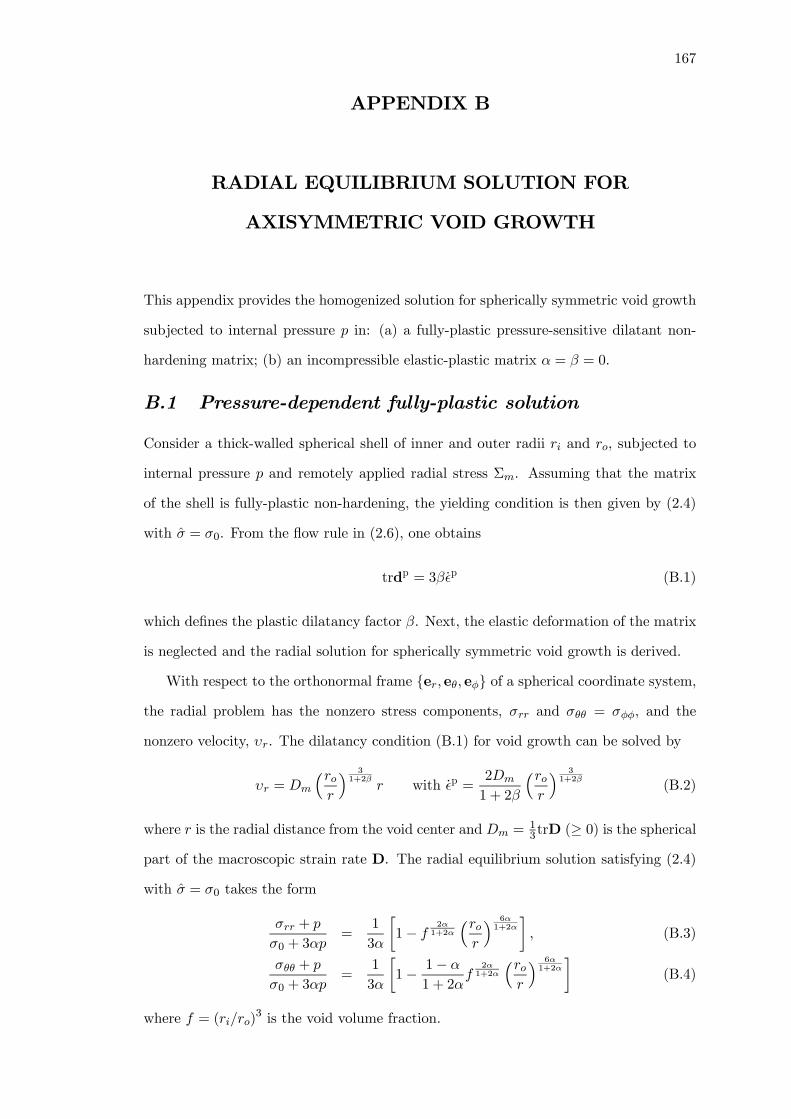
167
APPENDIX B
RADIAL EQUILIBRIUM SOLUTION FOR
AXISYMMETRIC VOID GROWTH
This appendix provides the homogenized solution for spherically symmetric void growth
subjected to internal pressure p in: (a) a fully-plastic pressure-sensitive dilatant non-
hardening matrix; (b) an incompressible elastic-plastic matrix α = β = 0.
B.1 Pressure-dependent fully-plastic solution
Consider a thick-walled spherical shell of inner and outer radii ri and ro, subjected to
internal pressure p and remotely applied radial stress Σm. Assuming that the matrix
of the shell is fully-plastic non-hardening, the yielding condition is then given by (2.4)
with σ = σ0. From the flow rule in (2.6), one obtains
trdp = 3β ˙p (B.1)
which defines the plastic dilatancy factor β. Next, the elastic deformation of the matrix
is neglected and the radial solution for spherically symmetric void growth is derived.
With respect to the orthonormal frame {er, eθ, eφ} of a spherical coordinate system,the radial problem has the nonzero stress components, σrr and σθθ = σφφ, and the
nonzero velocity, υr. The dilatancy condition (B.1) for void growth can be solved by
υr = Dm
³ror
´ 31+2β
r with ˙p =2Dm
1 + 2β
³ror
´ 31+2β
(B.2)
where r is the radial distance from the void center and Dm =13trD (≥ 0) is the spherical
part of the macroscopic strain rate D. The radial equilibrium solution satisfying (2.4)
with σ = σ0 takes the form
σrr + p
σ0 + 3αp=
1
3α
∙1− f
2α1+2α
³ror
´ 6α1+2α
¸, (B.3)
σθθ + p
σ0 + 3αp=
1
3α
∙1− 1− α
1 + 2αf
2α1+2α
³ror
´ 6α1+2α
¸(B.4)
where f = (ri/ro)3 is the void volume fraction.

168
From the conservation of mass in the unit cell, one can derive the evolution law for
the void volume fraction
f =³f
2β1+2β − f
´trD (B.5)
by using the radial velocity (B.2). Compared to the incompressible case β = 0, Eq.
(B.5) shows that nonzero plastic dilatancy suppresses the void growth rate.
Identifying the radial stress σrr at r = ro in (B.3) with the macroscopic mean stress
Σm yieldsΣm + p
σ0 + 3αp=1
3α
³1− f
2α1+2α
´. (B.6)
From this simple unit-cell analysis, one observes that the major influence of pressure-
sensitivity is on the macroscopic stresses. By contrast, plastic dilatancy mainly controls
the void growth rate and has little influence on the overall stresses.
Equation (B.6) can be considered as the macroscopic yielding condition for hydro-
static stress. As α→ 0, it reduces to the following form
2f cosh
µ3
2
Σm + p
σ0
¶− ¡1 + f2
¢= 0
which is the extended Gurson model (Guo and Cheng, 2002) for pressure-insensitive
solids, in the absence of the macroscopic Mises stress Σe.
B.2 Elastic-plastic solution, α = β = 0
For a spherical cavity in a finitely deformed incompressible elastic-plastic solid subjected
to internal vapor pressure p and externally applied radial stress Σm, Guo and Cheng
(2001) showed that the radial equilibrium solution takes the form
Σm + p
σ0=
Z ε2
ε1
H (ε)dε1− exp (−3ε/2) . (B.7)
Here, the uniaxial relationship between true stress and logarithmic strain of the material
is described by σ/σ0 = H (ε). For an elastic-plastic power law hardening solid, H (ε) =
ε/ε0 if |ε| < ε0; otherwise H (ε) = (|ε| /ε0)Nsign(ε) where ε0 = σ0/E is the reference
strain. The lower and upper integration limits ε1 and ε2 in (B.7) are the two-end strains
of the void, which can be determined solely by the current and initial void volume
fractions f and f0:
ε1 =2
3ln
µf0f
1− f
1− f0
¶, ε2 =
2
3ln
µ1− f
1− f0
¶. (B.8)
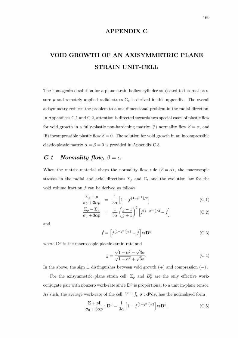
169
APPENDIX C
VOID GROWTH OF AN AXISYMMETRIC PLANE
STRAIN UNIT-CELL
The homogenized solution for a plane strain hollow cylinder subjected to internal pres-
sure p and remotely applied radial stress Σρ is derived in this appendix. The overall
axisymmetry reduces the problem to a one-dimensional problem in the radial direction.
In Appendices C.1 and C.2, attention is directed towards two special cases of plastic flow
for void growth in a fully-plastic non-hardening matrix: (i) normality flow β = α, and
(ii) incompressible plastic flow β = 0. The solution for void growth in an incompressible
elastic-plastic matrix α = β = 0 is provided in Appendix C.3.
C.1 Normality flow, β = α
When the matrix material obeys the normality flow rule (β = α) , the macroscopic
stresses in the radial and axial directions Σρ and Σz and the evolution law for the
void volume fraction f can be derived as follows
Σρ + p
σ0 + 3αp=
1
3α
h1− f(1−g
±1)/2i
(C.1)
Σρ − Σzσ0 + 3αp
=1
3α
µg − 1g + 1
¶2 hf(1−g
±1)/2 − fi
(C.2)
and
f =hf(1−g
±1)/2 − fitrDp (C.3)
where Dp is the macroscopic plastic strain rate and
g =
√1− α2 −√3α√1− α2 +
√3α
. (C.4)
In the above, the sign ± distinguishes between void growth (+) and compression (−) .For the axisymmetric plane strain cell, Σρ and Dp
ρ are the only effective work-
conjugate pair with nonzero work-rate since Dp is proportional to a unit in-plane tensor.
As such, the average work-rate of the cell, V −1RV σ : d
pdv, has the normalized form
Σ+ pI
σ0 + 3αp: Dp =
1
3α
h1− f(1−g
±1)/2itrDp. (C.5)
170
This formulation suggests an approximate work-rate equivalence between axisymmetric
and non-axisymmetric void growth (or compression), which can be used to estimate
the upper-limit stress level for a unit-cell with elastic-plastic matrix. The analytical
derivation is found to corroborate closely with the numerical results in Fig. 7.2.
Observe that the factor f(1−g±1)/2 − f in the range 0 ≤ α ≤ 1
2 is identically greater
than zero for both void growth and compression. Under normality flow conditions,
the radial stress Σρ is consistently greater than the axial stress Σz due to the plastic
dilatancy of the matrix. Thus Σρ −Σz in (C.2) defines the macroscopic effective stress.For void growth, the factor f (1−g)/2− f is not a monotonic decreasing function of f but
attains a maximum at
f∗ =µ1− g
2
¶2/(1+g). (C.6)
When α increases from 0 to 12 , f
∗ correspondingly increases from 0 to 14 , while the factor
f (1−g)/2−f decreases monotonically from 1 to 14 . Hence an increase in pressure-sensitivityα under an associated flow significantly reduces the void growth rate (C.3).
C.2 Incompressible plastic flow, β = 0
For incompressible plastic flow (β = 0) , the axisymmetric cell is under a state of pure
hydrostatic stress
Σz − Σρ = 0, Σρ + p
σ0 + 3αp=1
3α
³1− f
3α3α±√3
´(C.7)
and the void growth rate takes the classical form
f = (1− f) trDp. (C.8)
From (C.1) and (C.7), the effects of vapor pressure are noted to be less severe for
pressure-sensitive polymers, like the die-attach or molding compound in electronic pack-
ages.
In the limiting case of α→ 0, both flow rules considered above consistently leads to
the pure hydrostatic stress state
Σz − Σρ = 0, Σρ + p
σ0= ∓ 1√
3ln f (C.9)
and the classical void evolution law (C.8) as well. Equation (C.9) can be cast into the
171
macroscopic yield condition
2f cosh
Ã√3
2
Σγγ + 2p
σ0
!= 1 + f2 (C.10)
where Σγγ = Σx + Σy = 2Σρ. In the absence of internal pressure, this equation can
be identified with the Gurson model (Gurson, 1977) for cylindrical void growth with
vanishing macroscopic effective stress.
C.3 Elastic-plastic solution, α = β = 0
For a cylindrical cavity in a finitely deformed incompressible elastic-plastic solid sub-
jected to externally applied in-plane radial stress Σρ and internal pressure p, the radial
equilibrium solution takes the form:
Σρ + p
σ0=
Z ε2
ε1
H (ε)dε
1− exp ¡−√3ε¢ . (C.11)
Here, the uniaxial relationship between true stress and logarithmic strain of the material
is described by σ/σ0 = H (ε). For an elastic-plastic power law hardening solid, H (ε) =
ε/ε0 if |ε| < ε0; otherwise H (ε) = (|ε| /ε0)Nsign(ε) where ε0 = σ0/E is the reference
strain. The lower and upper integration limits ε1 and ε2 in (C.11) are the two-end
strains of the void, which can be determined solely by the current and initial void
volume fractions f0 and f :
ε1 =1√3ln
µf0f
1− f
1− f0
¶, ε2 =
1√3ln
µ1− f
1− f0
¶. (C.12)
A similar form to the integral in (C.11) was used by Huo et al. (1999).
172
APPENDIX D
STRAIN LOCALIZATION BEHAVIOR OF A
UNIT-CELL
To shed some light on the distinctive characteristics of softening-rehardening in poly-
mers (Fig. 8.13), the strain localization behavior of a representative material volume,
consisting of a periodic assemblage of hexagonal unit-cells, is examined. Each hexag-
onal cell can be approximated as a cylindrical cell containing a single spherical void.
A cylindrical coordinate system, with radial and axial coordinate directions (ρ, z), is
adopted in this appendix. Roller boundary conditions are applied along the symmetry
planes of the quarter geometry of the cell volume to be analyzed. The computations
are carried out under a prescribed stress triaxiality using the numerical procedure out-
lined by Smelser and Becker (1989), with the dominant loading in the axial direction.
The material parameters adopted for the axisymmetric unit-cell study are σ0/E = 0.01,
ν = 0.4, with f0 = 0.08.
The plastic strain contours of the representative unit-cell under stress triaxiality
levels of T = 2/3 and 2 are shown in Figs. D.1 and D.2 respectively for several levels of
effective strain Ee. Softening-rehardening parameters of η = 20 and 100 are considered.
The former represents a polymer with strong rehardening characteristics, while the latter
represents one with dominant softening response.
Under low stress triaxiality (Fig. D.1), the yielding characteristics for both η = 20
and 100 are similar. Plastic yielding initiates from the equator of the void at low loads,
with nucleation of several inclined shear bands from the void surface. At higher loads,
these shear bands propagate along the diagonal of the cell (near 60◦ inclination), with
nucleation of additional shear bands from the void surface. The plastic strain localizes
within each shear band under subsequent deformation.
Under high stress triaxiality (Fig. D.2), results indicate the absence of the diagonal
shear bands previously seen in Fig. D.1. Instead, the plastic yielding is mainly confined
to the horizontal ligament between neighboring voids for both η = 20 and 100.
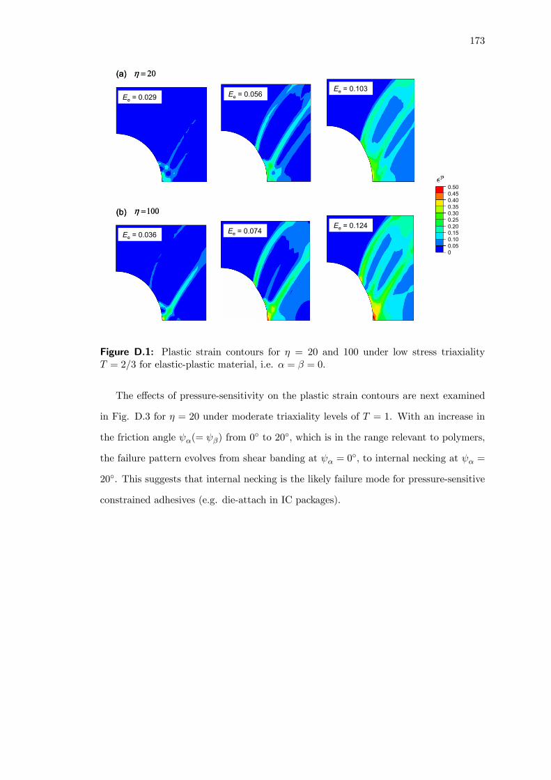
173
0.500.450.400.350.300.250.200.150.100.050
(a)
(b)
Ee = 0.029 Ee = 0.056Ee = 0.103
Ee = 0.036 Ee = 0.074Ee = 0.124
20=η
100=η
(a)
(b)
Ee = 0.029 Ee = 0.056Ee = 0.103
Ee = 0.036 Ee = 0.074Ee = 0.124
20=η
100=η
Figure D.1: Plastic strain contours for η = 20 and 100 under low stress triaxialityT = 2/3 for elastic-plastic material, i.e. α = β = 0.
The effects of pressure-sensitivity on the plastic strain contours are next examined
in Fig. D.3 for η = 20 under moderate triaxiality levels of T = 1. With an increase in
the friction angle ψα(= ψβ) from 0◦ to 20◦, which is in the range relevant to polymers,
the failure pattern evolves from shear banding at ψα = 0◦, to internal necking at ψα =
20◦. This suggests that internal necking is the likely failure mode for pressure-sensitive
constrained adhesives (e.g. die-attach in IC packages).
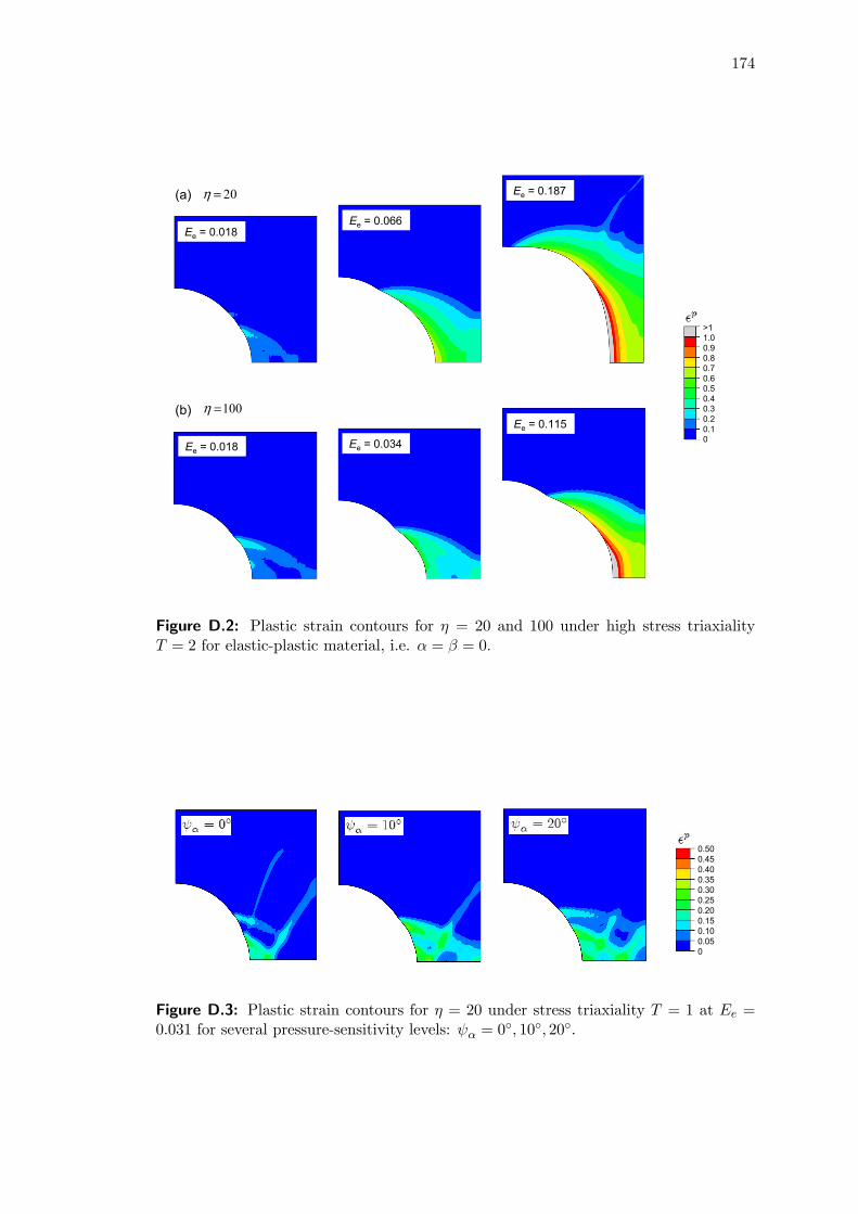
174
(a)
(b)
>11.00.90.80.70.60.50.40.30.20.10
Ee = 0.018Ee = 0.066
Ee = 0.187
Ee = 0.018 Ee = 0.034
Ee = 0.115
20=η
100=η
Figure D.2: Plastic strain contours for η = 20 and 100 under high stress triaxialityT = 2 for elastic-plastic material, i.e. α = β = 0.
0.500.450.400.350.300.250.200.150.100.050
Figure D.3: Plastic strain contours for η = 20 under stress triaxiality T = 1 at Ee =0.031 for several pressure-sensitivity levels: ψα = 0
◦, 10◦, 20◦.