Embed Size (px)
Citation preview

applied sciences
Article
A MBSE Application to Controllers of AutonomousUnderwater Vehicles Based on Model-DrivenArchitecture Concepts
Ngo Van Hien 1,* , Ngo Van He 1,* , Van-Thuan Truong 1,* and Ngoc-Tam Bui 2,3,*1 School of Transportation Engineering, Hanoi University of Science and Technology, Hanoi 10000, Vietnam2 College of Systems Engineering and Science, Shibaura Institute of Technology, Tokyo 135-8548, Japan3 School of Mechanical Engineering, Hanoi University of Science and Technology, Hanoi 10000, Vietnam* Correspondence: [email protected] (N.V.H.); [email protected] (N.V.H.);
[email protected] (V.-T.T.); [email protected] (N.-T.B.)
Received: 30 September 2020; Accepted: 21 November 2020; Published: 23 November 2020
Abstract: In this paper, a hybrid realization model is proposed for the controllers of autonomousunderwater vehicles (AUVs). This model is based on the model-based systems engineering (MBSE)methodology, in combination with the model-driven architecture (MDA), the real-time unifiedmodeling language (UML)/systems modeling language (SysML), the extended/unscented Kalmanfilter (EKF/UKF) algorithms, and hybrid automata, and it can be reused for designing controllersof various AUV types. The dynamic model and control structure of AUVs were combined withthe specialization of MDA concepts as follows. The computation-independent model (CIM) wasspecified by the use-case model combined with the EKF/UKF algorithms and hybrid automata tointensively gather the control requirements. Then, the platform-independent model (PIM) wasspecialized using the real-time UML/SysML to design the capsule collaboration of control and itsconnections. The detailed PIM was subsequently converted into the platform-specific model (PSM)using open-source platforms to promptly realize the AUV controller. On the basis of the proposedhybrid model, a planar trajectory-tracking controller, which allows a miniature torpedo-shaped AUVto autonomously track the desired planar trajectory, was implemented and evaluated, and shown tohave good feasibility.
Keywords: autonomous underwater vehicle (AUV); AUV control; extended/unscented Kalman filter(EKF/UKF); model-based systems engineering (MBSE); model-driven architecture (MDA); real-timeUML/SysML; hybrid automata
1. Introduction
Underwater vehicles have been extensively developed for many military applications in recentdecades. In particular, autonomous underwater vehicles (AUVs) are of interest with respectto developing civil applications for enhancing economic effectiveness, e.g., ocean exploration,environmental monitoring, mapping, and disaster and tsunami warnings [1–8].
Controller design for AUVs has been a challenge because controllers are closely linked to AUVdynamics in complex underwater environments [9–11]. The AUV controller can consist of discretemodels, continuous models, and their interaction in a hybrid dynamic system (HDS), as modeled byhybrid automata (HA) [12–15]. Traditional control methods have often been used for implementingcomplex systems to make them more effective for their controllers [16–18]. They have also been usedfor building AUV controllers. Some traditional control techniques applied for AUV applications aredescribed below.
Appl. Sci. 2020, 10, 8293; doi:10.3390/app10228293 www.mdpi.com/journal/applsci
Appl. Sci. 2020, 10, 8293 2 of 20
Lyapunov stability [19–22] was demonstrated to be very reactive. However, the stabilityof the desired waypoint was not suitable enough to track horizontal planar trajectories.The proportional–integral–derivative (PID) regulator [23–26] proved to be well suited for use inAUVs when tracking horizontal planar trajectories. It was possible to successfully perform the firstautonomous trip using this method. Nevertheless, the PID controller was implemented to controlthe AUV in the absence of large disturbances. The linear quadratic (LQ) [27,28] controller presentedaverage stabilization results. Backstepping methods [29,30] were shown to be able to control theEuler roll, pitch, and yaw (RPY) angles in conditions of high environmental noise. The sliding-modecontroller (SMC) [31–33] did not give good results when applied alone, as it seemed to be short ofadaptation for the dynamics of AUVs. Hence, in some studies investigating backstepping [34,35], neuralnetworks [36–39], the computed torque method [40,41], and digital filters such as extended/unscentedKalman filters (EKF/UKF), the SMC has been improved by using control techniques to improve itsperformance for AUVs.
The above assessment led to us choosing a combination of PID and backstepping to perform acontinuous model evolution of the AUV controller, called the integral backstepping (IB) technique.
Reusability must also be considered in the development of new AUV applications with respect totheir lifecycle in an effort to reduce their cost and resources. The Object Management Group (OMG) [42]standardized the unified modeling language (UML), which is as an industry standard used to visualize,specify, construct, and document the artefacts of a software-intensive system. The system modelinglanguage (SysML) [43] was standardized by the OMG for systems engineering. SysML is a UML profilethat can provide simple but powerful constructs for modeling a wide range of systems engineeringproblems. However, the drawback of UML and SysML is that they lack the ability to model theevolution of internal continuous behavior for developed systems.
On the other hand, the model-based systems engineering (MBSE) approach was formalized byINCOSE [44,45] to robustly model whole artefacts in the development lifecycle of unintelligible systems.Examples of systems engineering methods [46] were identified in a survey of MBSE methodologies [47],including Harmony for systems engineering (Harmony-SE) [48,49], the object-oriented systemsengineering method (OOSEM) [50,51], the rational unified process for systems engineering(RUP-SE) [52], the state analysis method [53], and the object process methodology (OPM) [54,55].The model-driven architecture (MDA) [56,57] was standardized by the OMG for separating thespecification of system operations from the details of how a system uses the capabilities of itsplatform. The three main goals of MDA are portability, interoperability, and reusability throughan architectural separation of concerns. Here, portability allows the same solution to be realizedon new or multiple platforms, while interoperability creates systems that can easily integrate andcommunicate with other systems and use a variety of resource applications, and reusability buildssolutions that can be reused in many different applications in different contexts [56]. Sebastián et al. [58]investigated MDA applications by conducting a systematic mapping of MDA literature in softwareengineering between 2008 and 2018. Actually, the principle of MDA can be used within the unifiedarchitecture framework (UAF) [59] to strengthen the interoperability of a system. In many commercialapplications, real-time SysML/UML has been combined with the above model-based methods forsystems engineering [57,60–67]. Hence, the MBSE approach and the features of MDA can be used incombination with real-time UML [68–71] and SysML (for example, real-time UML/SysML) to describe,in detail, the artefacts of the developed system.
On the basis of the above-assessed points, this work focuses on the construction of a hybridcontrol model based on the MBSE methodology, in combination with the MDA concept, real-timeUML/SysML, and HA, permitting us to intensively realize an AUV controller. The control artefactsdesigned can be customized and reused for deployment on various AUV platforms. In thisstudy, the dynamic models of AUV for control were combined with the specialization of MDAfeatures, composed of the platform-specific model (PSM), platform-independent model (PIM),and computation-independent model (CIM). Lastly, a planar trajectory-tracking controller for a

Appl. Sci. 2020, 10, 8293 3 of 20
miniature torpedo-shaped autonomous underwater vehicle running on a free surface was deployedand evaluated through simulation experiments.
The three main contributions of this research are as follows:
(1) The MBSE methodology, together with MDA components, was adapted for usability in thelifecycle development of AUV controllers.
(2) The designed control capsules are customizable and reusable for many kinds of AUVs.(3) A planar trajectory-tracking controller of a miniature AUV running on the free surface was
developed and evaluated through simulation experiments.
This manuscript is structured as follows. Section 2 presents the adapted dynamics and controlstructure of AUVs, while Section 3 proposes the details of MBSE-driven development aimed atintensively realizing AUV controllers, consisting of the CIM, PIM, and PSM components. A case studyon application of the specialized model is discussed in Section 4, followed by the paper’s conclusionsand future prospects.
2. AUV Dynamics and Control Architecture
2.1. AUV Dynamic Model for Controlling
The six motions of the AUV are defined as sway, surge, roll, heave, yaw, and pitch by the Societyof Naval Architects and Marine Engineers (SNAME [72] (Table 1).
Table 1. Society of Naval Architects and Marine Engineers (SNAME) notations for underwater vehicles(data from [64]).
Degree ofFreedom Motions Force and Moment Linear and
Angular VelocityPosition and Euler
Angles
1 Surge X u x2 Sway Y v y3 Heave Z w z4 Roll K p φ5 Pitch M q θ6 Yaw N r ψ
According to the guidance, navigation, and control of underwater vehicles [9,73–77], the kinematicmodel in the inertial frame and the dynamic model in the main frame of AUVs can be written asEquations (1) and (2), respectively.
.η=J(η)ν, (1)
M.ν+ C(ν)ν+ D(ν)ν+ g(η) = τ(v, u), (2)
where η = [η1T,η2
T]T consists of the position η1 = [x,y,z]T and the orientation η2 = [φ,θ,ψ]T of thevehicle expressed in the inertial frame, while ν = [v1
T,v2T]T includes the linear v1= [u,v,w]T and the
angular v2 = [p,q,r]T velocities of the vehicle expressed in the body frame. The model matrices M,C(ν), and D(ν) denote inertia, Coriolis, and damping, respectively, while g(η) is a vector of gravity andbuoyancy forces. On the right-hand side of Equation (2), τ(v,u) is the vector of resultant forces andmoments acting on the AUV, and u represents the control inputs.
A model of state-space discreteness can be used to model the control evolution of an AUV that isused to estimate the states of an AUV by using the EKF or UKF [78–82] methodologies; the motion ofthe control system can be described as shown in Equation (3).
xk = fk−1(xk−1, uk−1) + wk−1yk = hk(xk) + vk
(3)

Appl. Sci. 2020, 10, 8293 4 of 20
where x =
[ην
], xk is the state variable vector at the k-th instant of x, uk and yk are the system’s
inputs and outputs, respectively, and hk, wk, and vk are the measurement function, additive process,and measurement noise, respectively.
2.2. General Control Architecture for an AUV
The physical architecture of an AUV consists of the following subsystems: the guidance subsystem;the navigation subsystem; and the control subsystem. These subsystems have their own tasks, yet theymust also cooperate to permit the vehicle to complete its mission. Figure 1 shows a block definitiondiagram in SysML that depicts the interactions of the subsystems.
Appl. Sci. 2020, 10, x FOR PEER REVIEW 4 of 21
2.2. General Control Architecture for an AUV
The physical architecture of an AUV consists of the following subsystems: the guidance subsystem; the navigation subsystem; and the control subsystem. These subsystems have their own tasks, yet they must also cooperate to permit the vehicle to complete its mission. Figure 1 shows a block definition diagram in SysML that depicts the interactions of the subsystems.
Figure 1. Autonomy architecture block definition diagram for an autonomous underwater vehicle (AUV).
According to the above AUV dynamic and control architecture, and the definition of an HDS described in [13–15], AUV controllers can, thus, be considered HDSs whose dynamic behaviors can be modeled by HA [12] and implemented by line-of-sight (LOS) navigability, as described in [83–87].
3. MBSE-Driven Development for an AUV Controller
3.1. CIM for an AUV Controller
On the basis of the dynamics and control frame of AUVs described in Section 2, the main use case model of AUV controllers is shown in Figure 2. Figure 3a,b describes a case study of path-tracking scenarios, where the state machine of the “Track a desired trajectory” use case is shown using the sequence and state diagrams of real-time UML/SysML conventions.
The system/human actors and use cases of the AUV controller are defined as follows:
- MDS is the measurement display system actor, which includes the guidance subsystem and navigation subsystem.
- MES is the marine environment system actor, which represents the marine environmental noises.
- Maintainer is a human actor who has authority to check the physical AUV components and configure system parameters AUV for running AUV tasks.
- “Track a desired trajectory” is a use case study for tracking the target of a predefined path. - “Ensure safety” is a use case for ensuring system safety. - “Configure control parameters of the AUV” is a use case for configuring and updating system
parameters. - “Maintain the physical components” is a use case for servicing the whole physical system.
Figure 1. Autonomy architecture block definition diagram for an autonomous underwatervehicle (AUV).
According to the above AUV dynamic and control architecture, and the definition of an HDSdescribed in [13–15], AUV controllers can, thus, be considered HDSs whose dynamic behaviors can bemodeled by HA [12] and implemented by line-of-sight (LOS) navigability, as described in [83–87].
3. MBSE-Driven Development for an AUV Controller
3.1. CIM for an AUV Controller
On the basis of the dynamics and control frame of AUVs described in Section 2, the main use casemodel of AUV controllers is shown in Figure 2. Figure 3a,b describes a case study of path-trackingscenarios, where the state machine of the “Track a desired trajectory” use case is shown using thesequence and state diagrams of real-time UML/SysML conventions.
The system/human actors and use cases of the AUV controller are defined as follows:
- MDS is the measurement display system actor, which includes the guidance subsystem andnavigation subsystem.
- MES is the marine environment system actor, which represents the marine environmental noises.- Maintainer is a human actor who has authority to check the physical AUV components and
configure system parameters AUV for running AUV tasks.- “Track a desired trajectory” is a use case study for tracking the target of a predefined path.- “Ensure safety” is a use case for ensuring system safety.- “Configure control parameters of the AUV” is a use case for configuring and updating
system parameters.

Appl. Sci. 2020, 10, 8293 5 of 20
- “Maintain the physical components” is a use case for servicing the whole physical system.Appl. Sci. 2020, 10, x FOR PEER REVIEW 5 of 21
Figure 2. Use case model of the developed AUV.
(a) (b)
Figure 3. (a) Desired trajectory-tracking scenario, and (b) local state machine for performing the “track a desired trajectory” use case.
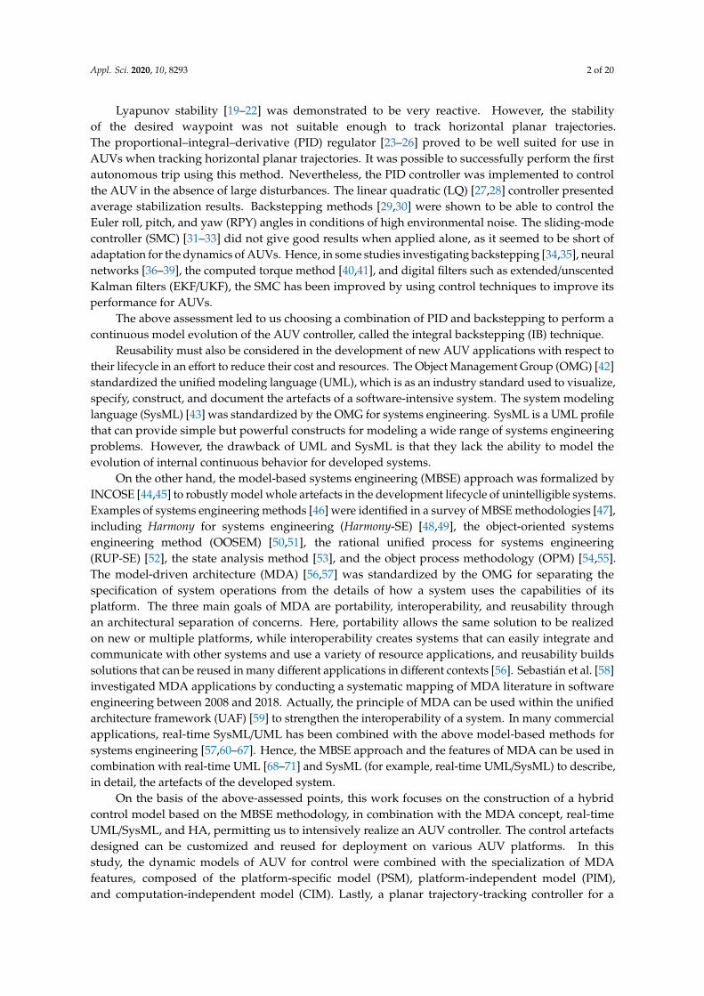
In this work, an implemented functional block diagram (Figure 4) is proposed for the kinematic and dynamic models of an AUV, described in Equations (1) and (2), to obtain the internal continuous evolutions for the controller, where Ωdi, 𝑖 = 1, 𝑛 are desired rotational speeds, which are applied to the n actuators of the AUV, and ΣT and τφ,θ,Ψ are the overall output forces and moments acting on the actuators of the AUV.
Figure 2. Use case model of the developed AUV.
Appl. Sci. 2020, 10, x FOR PEER REVIEW 5 of 21
Figure 2. Use case model of the developed AUV.
(a) (b)
Figure 3. (a) Desired trajectory-tracking scenario, and (b) local state machine for performing the “track a desired trajectory” use case.
In this work, an implemented functional block diagram (Figure 4) is proposed for the kinematic and dynamic models of an AUV, described in Equations (1) and (2), to obtain the internal continuous evolutions for the controller, where Ωdi, 𝑖 = 1, 𝑛 are desired rotational speeds, which are applied to the n actuators of the AUV, and ΣT and τφ,θ,Ψ are the overall output forces and moments acting on the actuators of the AUV.
Figure 3. (a) Desired trajectory-tracking scenario, and (b) local state machine for performing the “tracka desired trajectory” use case.
In this work, an implemented functional block diagram (Figure 4) is proposed for the kinematicand dynamic models of an AUV, described in Equations (1) and (2), to obtain the internal continuousevolutions for the controller, where Ωdi, i = 1, n are desired rotational speeds, which are applied to then actuators of the AUV, and ΣT and τφ,θ,Ψ are the overall output forces and moments acting on theactuators of the AUV.
Appl. Sci. 2020, 10, 8293 6 of 20Appl. Sci. 2020, 10, x FOR PEER REVIEW 6 of 21
Figure 4. Functional block diagram for implementing the continuous evolution of an AUV controller.
As previously assessed, the IB expansion combined with the control Lyapunov function (CLF) can be used in many AUV control applications. This was also applied to the functional blocks of deep control, position control, and attitude control (Figure 4), which participate in the continuous evolutions. PID regulators were also used for the functional block of motor control. This study did not focus on the decomposition of these control techniques for an AUV because they were developed in many AUV applications [23–26,34,35,88–90].
In addition, the discrete state-space models in Equation (3), in combination with the EKF or UKF [78–82] implementations, allowed the estimation of the states of the developed AUV, as introduced in Section 4.
Furthermore, hybrid automata (HA), presented by Henzinger, Kopke, Puri, and Varaiya [12], provide a mathematical model for digital computer systems that interact with an analog environment in real time. In the CIM, HA are established as shown in Equation (4).
HAUV = (Q, X, , A, Inv, F, qo, xco), (4)
where Q is a set of running cases of the AUV, qo ∈ Q is the starting situation, X is the continuous state-space of continuous elements, xco ∈ X is the initial value, is a set of external events, A is a set of transitions between running cases corresponding to events σ ∈ , Inv is an application tool, which is used to check xc ∈ inv(q), and F is the continuous global model issued from the kinematic and dynamic models in Equations (1) and (2).
3.2. PIM for an AUV Controller
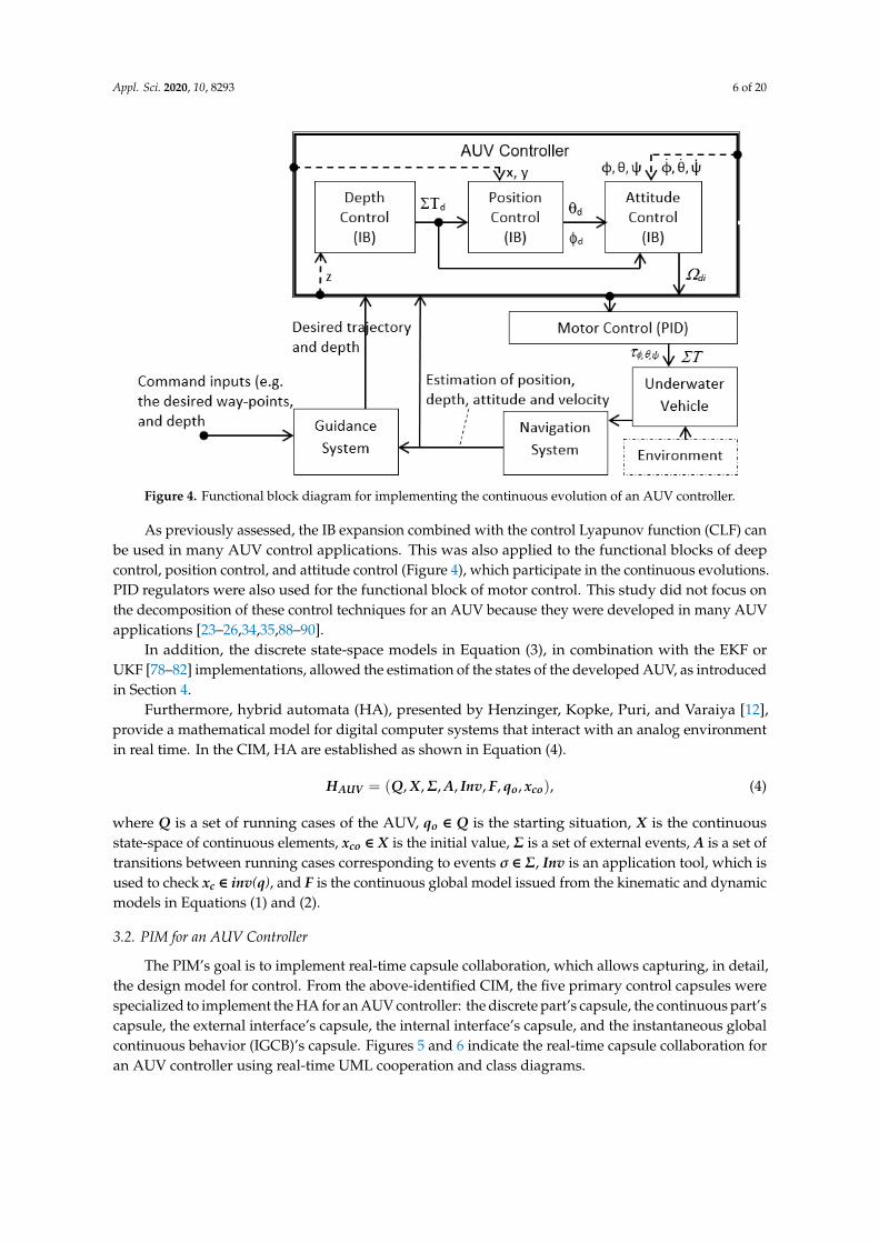
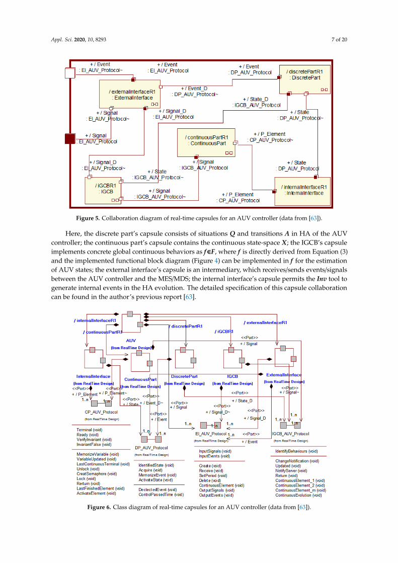
The PIM’s goal is to implement real-time capsule collaboration, which allows capturing, in detail, the design model for control. From the above-identified CIM, the five primary control capsules were specialized to implement the HA for an AUV controller: the discrete part’s capsule, the continuous part’s capsule, the external interface’s capsule, the internal interface’s capsule, and the instantaneous global continuous behavior (IGCB)’s capsule. Figures 5 and 6 indicate the real-time capsule collaboration for an AUV controller using real-time UML cooperation and class diagrams.
Figure 4. Functional block diagram for implementing the continuous evolution of an AUV controller.
As previously assessed, the IB expansion combined with the control Lyapunov function (CLF) canbe used in many AUV control applications. This was also applied to the functional blocks of deepcontrol, position control, and attitude control (Figure 4), which participate in the continuous evolutions.PID regulators were also used for the functional block of motor control. This study did not focus onthe decomposition of these control techniques for an AUV because they were developed in many AUVapplications [23–26,34,35,88–90].
In addition, the discrete state-space models in Equation (3), in combination with the EKF orUKF [78–82] implementations, allowed the estimation of the states of the developed AUV, as introducedin Section 4.
Furthermore, hybrid automata (HA), presented by Henzinger, Kopke, Puri, and Varaiya [12],provide a mathematical model for digital computer systems that interact with an analog environmentin real time. In the CIM, HA are established as shown in Equation (4).
HAUV = (Q, X,Σ, A, Inv, F, qo, xco), (4)
where Q is a set of running cases of the AUV, qo ∈ Q is the starting situation, X is the continuousstate-space of continuous elements, xco ∈ X is the initial value, Σ is a set of external events, A is a set oftransitions between running cases corresponding to events σ ∈ Σ, Inv is an application tool, which isused to check xc ∈ inv(q), and F is the continuous global model issued from the kinematic and dynamicmodels in Equations (1) and (2).
3.2. PIM for an AUV Controller
The PIM’s goal is to implement real-time capsule collaboration, which allows capturing, in detail,the design model for control. From the above-identified CIM, the five primary control capsules werespecialized to implement the HA for an AUV controller: the discrete part’s capsule, the continuous part’scapsule, the external interface’s capsule, the internal interface’s capsule, and the instantaneous globalcontinuous behavior (IGCB)’s capsule. Figures 5 and 6 indicate the real-time capsule collaboration foran AUV controller using real-time UML cooperation and class diagrams.
Appl. Sci. 2020, 10, 8293 7 of 20Appl. Sci. 2020, 10, x FOR PEER REVIEW 7 of 21
Figure 5. Collaboration diagram of real-time capsules for an AUV controller (data from [63]).
Here, the discrete part’s capsule consists of situations Q and transitions A in HA of the AUV controller; the continuous part’s capsule contains the continuous state-space X; the IGCB’s capsule implements concrete global continuous behaviors as f∈F, where f is directly derived from Equation (3) and the implemented functional block diagram (Figure 4) can be implemented in f for the estimation of AUV states; the external interface’s capsule is an intermediary, which receives/sends events/signals between the AUV controller and the MES/MDS; the internal interface’s capsule permits the Inv tool to generate internal events in the HA evolution. The detailed specification of this capsule collaboration can be found in the author’s previous report [63].
Figure 6. Class diagram of real-time capsules for an AUV controller (data from [63]).
Figure 5. Collaboration diagram of real-time capsules for an AUV controller (data from [63]).
Here, the discrete part’s capsule consists of situations Q and transitions A in HA of the AUVcontroller; the continuous part’s capsule contains the continuous state-space X; the IGCB’s capsuleimplements concrete global continuous behaviors as f∈F, where f is directly derived from Equation (3)and the implemented functional block diagram (Figure 4) can be implemented in f for the estimationof AUV states; the external interface’s capsule is an intermediary, which receives/sends events/signalsbetween the AUV controller and the MES/MDS; the internal interface’s capsule permits the Inv tool togenerate internal events in the HA evolution. The detailed specification of this capsule collaborationcan be found in the author’s previous report [63].
Appl. Sci. 2020, 10, x FOR PEER REVIEW 7 of 21
Figure 5. Collaboration diagram of real-time capsules for an AUV controller (data from [63]).
Here, the discrete part’s capsule consists of situations Q and transitions A in HA of the AUV controller; the continuous part’s capsule contains the continuous state-space X; the IGCB’s capsule implements concrete global continuous behaviors as f∈F, where f is directly derived from Equation (3) and the implemented functional block diagram (Figure 4) can be implemented in f for the estimation of AUV states; the external interface’s capsule is an intermediary, which receives/sends events/signals between the AUV controller and the MES/MDS; the internal interface’s capsule permits the Inv tool to generate internal events in the HA evolution. The detailed specification of this capsule collaboration can be found in the author’s previous report [63].
Figure 6. Class diagram of real-time capsules for an AUV controller (data from [63]). Figure 6. Class diagram of real-time capsules for an AUV controller (data from [63]).

Appl. Sci. 2020, 10, 8293 8 of 20
Reusability is essential in the operator of controllers for different AUV applications because itreduces manufacturing time and equipment costs. Moreover, this can allow the capsule collaborationof a developed AUV to be customized and reused in a new control application for many types of AUVs,as shown in Table 2.
Table 2. The customizability and reusability of designed control capsules in new control applicationsfor many types of AUVs. IGCB, instantaneous global continuous behavior.
Designed ControlCapsules
Specialization Rules
Generic Artifacts the NewAUV Controller
Specialized Artifacts the NewAUV Controller
IGCB The state machine, ports, and protocols ofthis capsule are not changed.
The specifications of the IGCB’s capsule makeup the new IGCB model and are formed by the
new continuous components.
Continuous part The ports and protocols of this capsule arenot changed.
It is specialized by adding or removing downcontinuous elements.
Discrete capsule This is not changed. None.
External interface The state machine, ports, and protocols ofthis capsule are not changed.
It is specialized by adding/removinginputs/outputs events issued from the outside.
Internal interface The state machine and ports of thiscapsule are not changed.
It is specialized by adding/removing Invin/from the new IGCB.
The real-time capsule collaborations shown in Figures 5 and 6 are not changed for new control applications of AUVs.
3.3. PSM for an AUV Controller
In the construction of the AUV controller, the above-designed PIM was converted into the PSMusing IBM Rational Software Architect Real Time, IBM Rational Rose Real Time [91], or Papyrusfor Real Time (Papyrus-RT) [92]. These tools are effectively used to develop complex real-time andembedded systems and software applications. They act as implementations of real-time UML/SysMLfor C++, Java, Ada, and runtime system supports.
Hence, the PIM could be converted into the PSM using different implementation developmentenvironments (IDEs) to ultimately realize a controller with suitable microcontrollers. The MDA’sfeatures also support model transformation. This transformation model could be rapidly appliedthrough round-trip engineering. The transformation rules, which can be used to convert the PIM intoPSM and vice versa through round-trip engineering of the intermediate codes of an object-orientedprogramming language, were presented in the authors’ previous report [1].
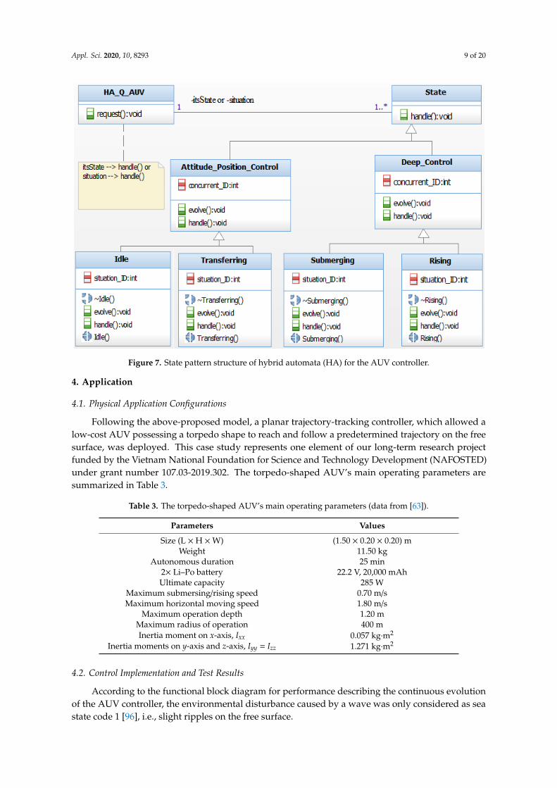
Furthermore, the above-defined HA could be automatically implemented using the state patterndescribed in [93,94]. According to this pattern, the HA’s structure implementation to display themeaningful programming usefulness of the control program of an AUV is shown in Figure 7.An example of HA implementation based on the state pattern was performed and compiled usingArduino’s IDE [95] to fit into ATMEGA32-U2 and STM32 Cortex-M4 microcontrollers for an AUVcontroller, as shown in Appendix A.
Appl. Sci. 2020, 10, 8293 9 of 20
Appl. Sci. 2020, 10, x FOR PEER REVIEW 9 of 21
Figure 7. State pattern structure of hybrid automata (HA) for the AUV controller.
4. Application
4.1. Physical Application Configurations
Following the above-proposed model, a planar trajectory-tracking controller, which allowed a low-cost AUV possessing a torpedo shape to reach and follow a predetermined trajectory on the free surface, was deployed. This case study represents one element of our long-term research project funded by the Vietnam National Foundation for Science and Technology Development (NAFOSTED) under grant number 107.03-2019.302. The torpedo-shaped AUV’s main operating parameters are summarized in Table 3.
Table 3. The torpedo-shaped AUV’s main operating parameters (data from [63]).
Parameters Values Size (L × H × W) (1.50 × 0.20 × 0.20) m
Weight 11.50 kg Autonomous duration 25 min
2× Li–Po battery 22.2 V, 20,000 mAh Ultimate capacity 285 W
Maximum submersing/rising speed 0.70 m/s Maximum horizontal moving speed 1.80 m/s
Maximum operation depth 1.20 m Maximum radius of operation 400 m Inertia moment on x-axis, Ixx 0.057 kg·m2
Inertia moments on y-axis and z-axis, Iyy = Izz 1.271 kg·m2
4.2. Control Implementation and Test Results
According to the functional block diagram for performance describing the continuous evolution of the AUV controller, the environmental disturbance caused by a wave was only considered as sea state code 1 [96], i.e., slight ripples on the free surface.
Figure 7. State pattern structure of hybrid automata (HA) for the AUV controller.
4. Application
4.1. Physical Application Configurations
Following the above-proposed model, a planar trajectory-tracking controller, which allowed alow-cost AUV possessing a torpedo shape to reach and follow a predetermined trajectory on the freesurface, was deployed. This case study represents one element of our long-term research projectfunded by the Vietnam National Foundation for Science and Technology Development (NAFOSTED)under grant number 107.03-2019.302. The torpedo-shaped AUV’s main operating parameters aresummarized in Table 3.
Table 3. The torpedo-shaped AUV’s main operating parameters (data from [63]).
Parameters Values
Size (L × H ×W) (1.50 × 0.20 × 0.20) mWeight 11.50 kg
Autonomous duration 25 min2× Li–Po battery 22.2 V, 20,000 mAhUltimate capacity 285 W
Maximum submersing/rising speed 0.70 m/sMaximum horizontal moving speed 1.80 m/s
Maximum operation depth 1.20 mMaximum radius of operation 400 mInertia moment on x-axis, Ixx 0.057 kg·m2
Inertia moments on y-axis and z-axis, Iyy = Izz 1.271 kg·m2
4.2. Control Implementation and Test Results
According to the functional block diagram for performance describing the continuous evolutionof the AUV controller, the environmental disturbance caused by a wave was only considered as seastate code 1 [96], i.e., slight ripples on the free surface.
Appl. Sci. 2020, 10, 8293 10 of 20
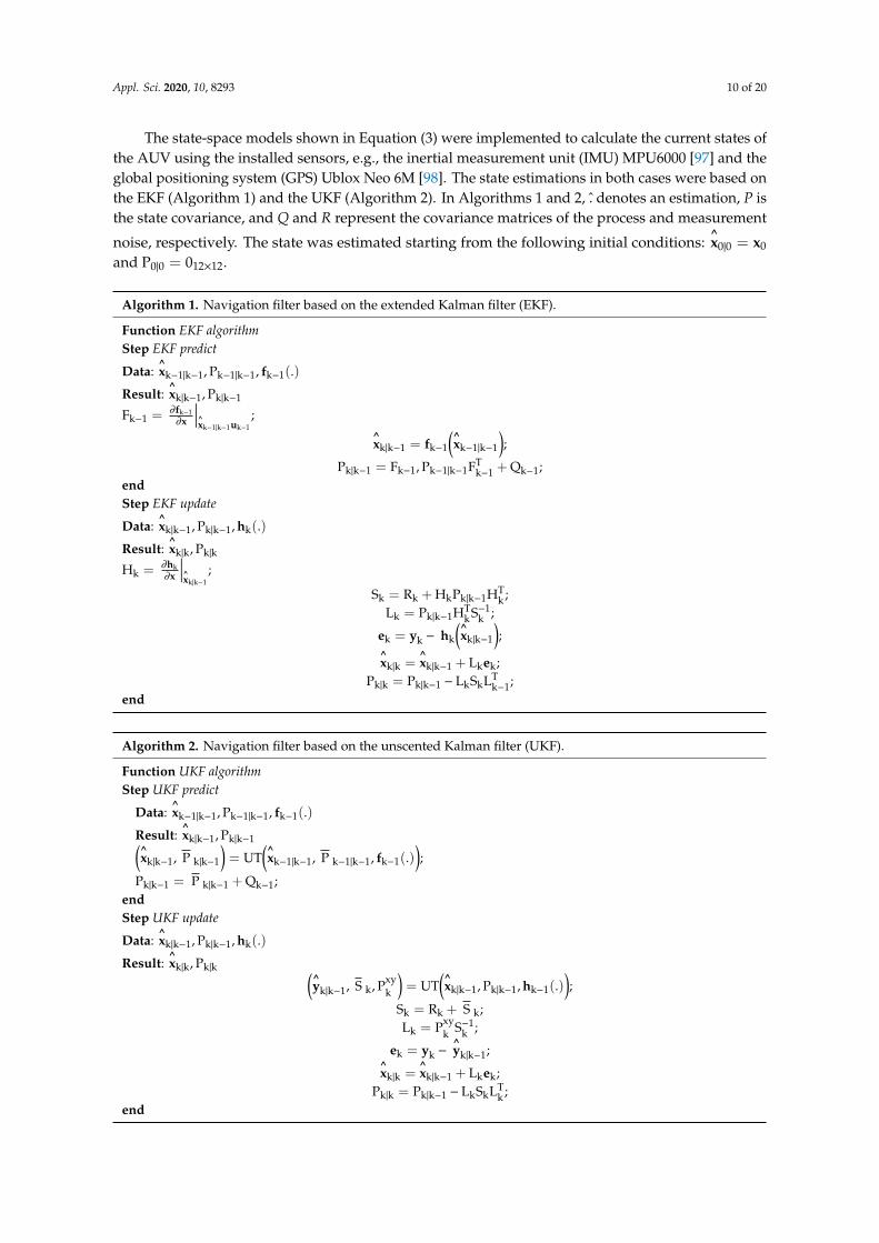
The state-space models shown in Equation (3) were implemented to calculate the current states ofthe AUV using the installed sensors, e.g., the inertial measurement unit (IMU) MPU6000 [97] and theglobal positioning system (GPS) Ublox Neo 6M [98]. The state estimations in both cases were based onthe EKF (Algorithm 1) and the UKF (Algorithm 2). In Algorithms 1 and 2, . denotes an estimation, P isthe state covariance, and Q and R represent the covariance matrices of the process and measurement
noise, respectively. The state was estimated starting from the following initial conditions:^x0|0 = x0
and P0|0 = 012×12.
Algorithm 1. Navigation filter based on the extended Kalman filter (EKF).
Function EKF algorithmStep EKF predict
Data:^xk−1|k−1, Pk−1|k−1, fk−1(.)
Result:^xk|k−1, Pk|k−1
Fk−1 = ∂fk−1∂x
∣∣∣∣^xk−1|k−1uk−1
;^xk|k−1 = fk−1
(^xk−1|k−1
);
Pk|k−1 = Fk−1, Pk−1|k−1FTk−1 + Qk−1;
endStep EKF update
Data:^xk|k−1, Pk|k−1, hk(.)
Result:^xk|k, Pk|k
Hk = ∂hk∂x
∣∣∣∣^xk|k−1
;
Sk = Rk + HkPk|k−1HTk ;
Lk = Pk|k−1HTkS−1
k ;
ek = yk − hk
(^xk|k−1
);
^xk|k =
^xk|k−1 + Lkek;
Pk|k = Pk|k−1 − LkSkLTk−1;
end
Algorithm 2. Navigation filter based on the unscented Kalman filter (UKF).
Function UKF algorithmStep UKF predict
Data:^xk−1|k−1, Pk−1|k−1, fk−1(.)
Result:^xk|k−1, Pk|k−1(
^xk|k−1, P k|k−1
)= UT
(^xk−1|k−1, P k−1|k−1, fk−1(.)
);
Pk|k−1 = P k|k−1 + Qk−1;endStep UKF update
Data:^xk|k−1, Pk|k−1, hk(.)
Result:^xk|k, Pk|k (
^yk|k−1, S k, Pxy
k
)= UT
(^xk|k−1, Pk|k−1, hk−1(.)
);
Sk = Rk + S k;Lk = Pxy
k S−1k ;
ek = yk −^yk|k−1;
^xk|k =
^xk|k−1 + Lkek;
Pk|k = Pk|k−1 − LkSkLTk ;
end

Appl. Sci. 2020, 10, 8293 11 of 20
We used the OpenModelica tool [99], which is an open-source simulation environment, to performthe simulation of an AUV controller. OpenModelica is an object-oriented modeling environment ofModelica [100] and C/C++ for hybrid systems. A case study in which the MDS was assumed to addressan event in the transferring state to the AUV controller with a desired course angle of 020 and averagespeed of 1.5 m/s is shown in Figure 8. Here, the average transient durations, which correspond to thecases using EKF and UKF, were 6.8 and 6.2 s for the AUV’s stabilized course.
Appl. Sci. 2020, 10, x FOR PEER REVIEW 11 of 21
L = P S ; 𝐞 = 𝐲 − 𝐲 | ; 𝐱 | = 𝐱 | + L 𝐞 ; P | = P | − L S L ; end
We used the OpenModelica tool [99], which is an open-source simulation environment, to perform the simulation of an AUV controller. OpenModelica is an object-oriented modeling environment of Modelica [100] and C/C++ for hybrid systems. A case study in which the MDS was assumed to address an event in the transferring state to the AUV controller with a desired course angle of 020° and average speed of 1.5 m/s is shown in Figure 8. Here, the average transient durations, which correspond to the cases using EKF and UKF, were 6.8 and 6.2 s for the AUV’s stabilized course.
Figure 8. Average transient response time in a desired course of 020o from the current position for the cases using EKF and UKF.
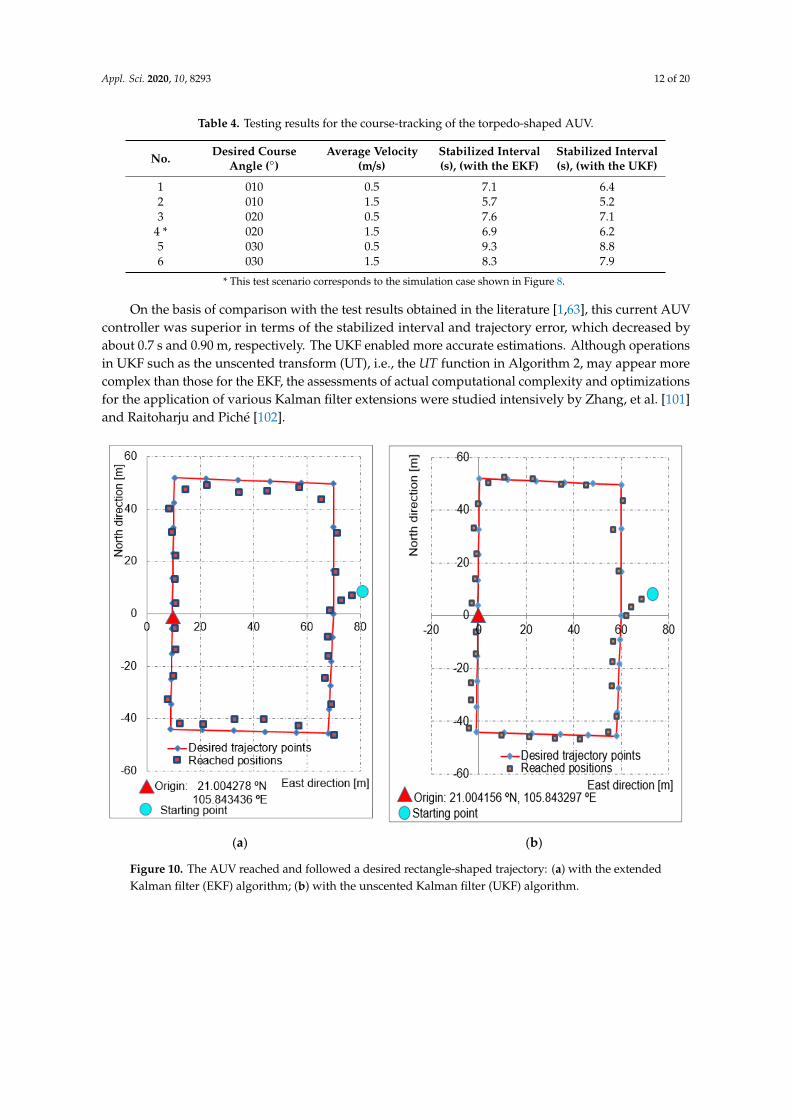
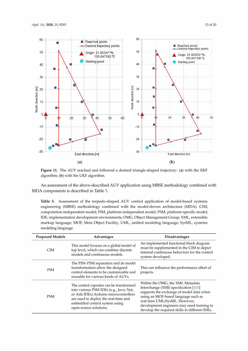
The ATMEGA32-U2 and STM32 Cortex-M4 microcontrollers [95] were installed on the mainboard. The AUV installation for trial trips is shown in Figure 9. The test scenarios were based on different desired courses, for various desired shape-based paths and average velocities. Some of the main planar course-tracking test results are shown in Table 4. Figures 10a,b and 11a,b respectively show that the AUV reached and followed the desired rectangle- and triangle-shaped trajectories.
Figure 8. Average transient response time in a desired course of 020 from the current position for thecases using EKF and UKF.
The ATMEGA32-U2 and STM32 Cortex-M4 microcontrollers [95] were installed on the mainboard.The AUV installation for trial trips is shown in Figure 9. The test scenarios were based on differentdesired courses, for various desired shape-based paths and average velocities. Some of the main planarcourse-tracking test results are shown in Table 4. Figure 10a,b and Figure 11a,b respectively show thatthe AUV reached and followed the desired rectangle- and triangle-shaped trajectories.Appl. Sci. 2020, 10, x FOR PEER REVIEW 12 of 21
Figure 9. AUV installation for trial trips.
Table 4. Testing results for the course-tracking of the torpedo-shaped AUV.
No. Desired Course Angle (°)
Average Velocity (m/s)
Stabilized Interval (s), (with the EKF)
Stabilized Interval (s), (with the UKF)
1 010 0.5 7.1 6.4 2 010 1.5 5.7 5.2 3 020 0.5 7.6 7.1
4 * 020 1.5 6.9 6.2 5 030 0.5 9.3 8.8 6 030 1.5 8.3 7.9
* This test scenario corresponds to the simulation case shown in Figure 8.
On the basis of comparison with the test results obtained in the literature [1,63], this current AUV controller was superior in terms of the stabilized interval and trajectory error, which decreased by about 0.7 s and 0.90 m, respectively. The UKF enabled more accurate estimations. Although operations in UKF such as the unscented transform (UT), i.e., the UT function in Algorithm 2, may appear more complex than those for the EKF, the assessments of actual computational complexity and optimizations for the application of various Kalman filter extensions were studied intensively by Zhang, et al. [101] and Raitoharju and Piché [102].
Figure 9. AUV installation for trial trips.
Appl. Sci. 2020, 10, 8293 12 of 20
Table 4. Testing results for the course-tracking of the torpedo-shaped AUV.
No. Desired CourseAngle ()
Average Velocity(m/s)
Stabilized Interval(s), (with the EKF)
Stabilized Interval(s), (with the UKF)
1 010 0.5 7.1 6.42 010 1.5 5.7 5.23 020 0.5 7.6 7.1
4 * 020 1.5 6.9 6.25 030 0.5 9.3 8.86 030 1.5 8.3 7.9
* This test scenario corresponds to the simulation case shown in Figure 8.
On the basis of comparison with the test results obtained in the literature [1,63], this current AUVcontroller was superior in terms of the stabilized interval and trajectory error, which decreased byabout 0.7 s and 0.90 m, respectively. The UKF enabled more accurate estimations. Although operationsin UKF such as the unscented transform (UT), i.e., the UT function in Algorithm 2, may appear morecomplex than those for the EKF, the assessments of actual computational complexity and optimizationsfor the application of various Kalman filter extensions were studied intensively by Zhang, et al. [101]and Raitoharju and Piché [102].Appl. Sci. 2020, 10, x FOR PEER REVIEW 13 of 21
(a) (b)
Figure 10. The AUV reached and followed a desired rectangle-shaped trajectory: (a) with the extended Kalman filter (EKF) algorithm; (b) with the unscented Kalman filter (UKF) algorithm.
(a) (b)
Figure 11. The AUV reached and followed a desired triangle-shaped trajectory: (a) with the EKF algorithm; (b) with the UKF algorithm.
Figure 10. The AUV reached and followed a desired rectangle-shaped trajectory: (a) with the extendedKalman filter (EKF) algorithm; (b) with the unscented Kalman filter (UKF) algorithm.
Appl. Sci. 2020, 10, 8293 13 of 20
Appl. Sci. 2020, 10, x FOR PEER REVIEW 13 of 21
(a) (b)
Figure 10. The AUV reached and followed a desired rectangle-shaped trajectory: (a) with the extended Kalman filter (EKF) algorithm; (b) with the unscented Kalman filter (UKF) algorithm.
(a) (b)
Figure 11. The AUV reached and followed a desired triangle-shaped trajectory: (a) with the EKF algorithm; (b) with the UKF algorithm. Figure 11. The AUV reached and followed a desired triangle-shaped trajectory: (a) with the EKFalgorithm; (b) with the UKF algorithm.
An assessment of the above-described AUV application using MBSE methodology combined withMDA components is described in Table 5.
Table 5. Assessment of the torpedo-shaped AUV control application of model-based systemsengineering (MBSE) methodology combined with the model-driven architecture (MDA). CIM,computation-independent model; PIM, platform-independent model; PSM, platform-specific model;IDE, implementation development environments; OMG, Object Management Group; XML, extensiblemarkup language; MOF, Meta Object Facility; UML, unified modeling language; SysML, systemsmodeling language.
Proposed Models Advantages Disadvantages
CIMThis model focuses on a global model oftop level, which can combine discretemodels and continuous models.
An implemented functional block diagrammust be supplemented in the CIM to depictinternal continuous behaviors for the controlsystem developed.
PIM
The PIM–PSM separation and its modeltransformation allow the designedcontrol elements to be customizable andreusable for various kinds of AUVs.
This can influence the performance effort ofprojects.
PSM
The control capsules can be transformedinto various PSM IDEs (e.g., Java, Net,or Ada IDEs).Arduino microcontrollersare used to deploy the real-time andembedded control system usingopen-source solutions.
Within the OMG, the XML MetadataInterchange (XMI) specification [103]supports the exchange of model data whenusing an MOF-based language such asreal-time UML/SysML. However,development engineers may need training todevelop the required skills in different IDEs.
Appl. Sci. 2020, 10, 8293 14 of 20
5. Conclusions and Future Work
This paper introduced an application of MBSE methodology to intensively deploy controllersfor AUVs whose dynamics can be considered an HDS. This application model is based on the MBSEmethodology, combined with MDA concepts, real-time UML/SysML, EKF/UKF algorithms, and HA tosystematically realize the controller. The dynamic models and control structure of AUV were first usedfor control combined with MDA components such as the CIM, PIM, and PSM. In the CIM, the use casemodel was defined with continuous behaviors, EKF/UKF algorithms, and HA to closely control therequirements. The PIM was established to establish the design model by constructing a real-time capsulepattern. This pattern can be customized and reused in new AUV control applications (Table 2). The PIMdesigned was then converted into the PSM through round-trip engineering of the intermediate C++
codes to form an AUV controller with suitable microcontrollers. On the basis of the proposed model,a planar trajectory-tracking controller of a miniature torpedo-shaped AUV running on the free surfacewas implemented and evaluated using the ATMEGA U2 and STM32-Cortex-M4 microcontrollers.Lastly, the advantages and disadvantages of the MBSE/MDA approach were discussed with respect tothis AUV control application (Table 5).
In this case study, the above-described MBSE methodology, combined with MDA concepts,was only applied to simple test scenarios for a miniature torpedo-shaped AUV running on the freesurface. We are yet to fine-tune parameters with respect to the process and measurement noise and theevolutionary optimization for noise parameters for this application. Thus, these important furtherdevelopments are scheduled for the future. Firstly, the EKF/UKF-based navigation filters will besimulated online within a complete AUV combined with depth control and a suitable environment.Then, the new controller will be implemented on the AUV and tested online through fast frequencydisturbances. The performances of the different Kalman filter extensions in terms of accuracy willbe carefully investigated in different scenarios. In further MBSE/MDA studies, we will also followour application strategy to specify, in detail, the patterns of model transformations using the differentMDA transformation types, and we will compare them to cases using OPM, such as those describedin [54,55].
Author Contributions: Conceptualization, N.V.H. (Ngo Van Hien), N.V.H. (Ngo Van He), V.-T.T. and N.-T.B.;methodology, N.V.H. (Ngo Van Hien), N.V.H. (Ngo Van He), V.-T.T. and N.-T.B.; software, N.V.H. (Ngo Van Hien),N.V.H. (Ngo Van He), and V.-T.T.; validation, N.V.H. (Ngo Van Hien), N.V.H. (Ngo Van He), V.-T.T. and N.-T.B.;writing—original draft preparation, N.V.H. (Ngo Van Hien), N.V.H. (Ngo Van He), and V.-T.T.; writing—reviewand editing N.V.H. (Ngo Van Hien), N.V.H. (Ngo Van He), V.-T.T. and N.-T.B.; visualization, N.V.H. (Ngo VanHien), N.V.H. (Ngo Van He), V.-T.T. and N.-T.B.; supervision, N.V.H. (Ngo Van Hien); project administration,N.V.H. (Ngo Van He); funding acquisition, N.-T.B. All authors have read and agreed to the published version ofthe manuscript.
Funding: Vietnam National Foundation for Science and Technology Development (NAFOSTED).
Acknowledgments: This research was funded by the Vietnam National Foundation for Science and TechnologyDevelopment (NAFOSTED) under grant number 107.03-2019.302. The authors would like to warmly express theirthanks for the support.
Conflicts of Interest: The authors declare no conflict of interest.
Abbreviations
AUV Autonomous underwater vehicle MES Marine environment systemCIM Computation independent model MOF Meta Object FacilityCLF Control Lyapunov functions OMG Object Management GroupDoF Degrees of freedom OOSEM Object-Oriented Systems Engineering MethodEKF Extended Kalman filter OPM Object Process MethodologyGPS Global positioning system PID Proportional–integral–derivativeHA Hybrid automata PIM Platform independent modelHarmony-SE Harmony for systems engineering PSM Platform specific modelHDS Hybrid dynamic system RPY Roll, pitch, and yaw

Appl. Sci. 2020, 10, 8293 15 of 20
IB Integral backstepping RUP-SERational Unified Process for SystemsEngineering
INCOSEInternational Council on SystemsEngineering
SMC Sliding-mode control
IDEImplementation developmentenvironment
SNAMESociety of Naval Architects and MarineEngineers
IGCBInstantaneous global continuousbehavior
SysML Systems modeling language
IMU Inertial measurement unit UAF Unified architecture frameworkLQ Linear quadratic UKF Unscented Kalman filterLOS Line-of-sight UML Unified modeling languageMBSE Model-based systems engineering UT Unscented transformMDA Model-driven architecture XMI XML metadata interchangeMDS Measurement display system XML Extensible markup language
Appendix A
An example of HA implementation based on the state pattern (Figure 7) and C++ codes is shown asFigure A1.
Appl. Sci. 2020, 10, x FOR PEER REVIEW 16 of 21
Figure A1. An example of HA implementation based on the state pattern.
References
1. Hien, N.V.; He, N.V.; Truong, V.T.; Diem, P.G. Specifying the Model-Driven Architecture and Real-Time Unified Modeling Language to Implement an AUV Controller. Research Project Report, Funded by State of Vietnam, KC03.TN05/11-15; Hanoi University of Science and Technology: Hanoi, Vietnam, 2013.
2. Sivčev, S.; Coleman, J.; Omerdić, E.; Dooly, G.; Toal, D. Underwater manipulators: A review. Ocean Eng. 2018, 163, 431–450, doi:10.1016/j.oceaneng.2018.06.018.
3. Wynn, R.B.; Huvenne, V.A.I.; Bas, T.P.L.; Murton, B.J.; Connelly, D.P.; Bett, B.J.; Ruhl, H.A.; Morris, K.J.; Peakall, J.; Parsons, D.R.; et al. Autonomous Underwater Vehicles (AUVs): Their past, present and future contributions to the advancement of marine geoscience. Mar. Geol. -Int. J. Mar. Geol. Geochem. Geophys. 2014, 352, 451–468, doi:10.1016/j.margeo.2014.03.012.
4. Petillot, Y.R.; Antonelli, G.; Casalino, G.; Ferreira, F. Underwater Robots: From Remotely Operated Vehicles to Intervention-Autonomous Underwater Vehicles. IEEE Robot. Autom. Mag. 2019, 26, 94–101, doi:10.1109/MRA.2019.2908063.
Figure A1. An example of HA implementation based on the state pattern.
Appl. Sci. 2020, 10, 8293 16 of 20
References
1. Hien, N.V.; He, N.V.; Truong, V.T.; Diem, P.G. Specifying the Model-Driven Architecture and Real-Time UnifiedModeling Language to Implement an AUV Controller. Research Project Report, Funded by State of Vietnam,KC03.TN05/11-15; Hanoi University of Science and Technology: Hanoi, Vietnam, 2013.
2. Sivcev, S.; Coleman, J.; Omerdic, E.; Dooly, G.; Toal, D. Underwater manipulators: A review. Ocean Eng.2018, 163, 431–450. [CrossRef]
3. Wynn, R.B.; Huvenne, V.A.I.; Bas, T.P.L.; Murton, B.J.; Connelly, D.P.; Bett, B.J.; Ruhl, H.A.; Morris, K.J.;Peakall, J.; Parsons, D.R.; et al. Autonomous Underwater Vehicles (AUVs): Their past, present and futurecontributions to the advancement of marine geoscience. Mar. Geol. Int. J. Mar. Geol. Geochem. Geophys. 2014,352, 451–468. [CrossRef]
4. Petillot, Y.R.; Antonelli, G.; Casalino, G.; Ferreira, F. Underwater Robots: From Remotely Operated Vehiclesto Intervention-Autonomous Underwater Vehicles. IEEE Robot. Autom. Mag. 2019, 26, 94–101. [CrossRef]
5. Han, M.; Lyu, Z.; Qiu, T.; Xu, M. A Review on Intelligence Dehazing and Color Restoration for UnderwaterImages. IEEE Trans. Syst. Man Cybern. Syst. 2020, 50, 1820–1832. [CrossRef]
6. Bao, J.; Li, D.; Qiao, X.; Rauschenbach, T. Integrated navigation for autonomous underwater vehicles inaquaculture: A review. Inf. Process. Agric. 2020, 7, 139–151. [CrossRef]
7. Eiler, J.H.; Grothues, T.M.; Dobarro, J.A.; Shome, R. Tracking the Movements of Juvenile Chinook SalmonUsing an Autonomous Underwater Vehicle under Payload Control. Appl. Sci. 2019, 9, 2516. [CrossRef]
8. Sheng, M.; Tang, S.; Qin, H.; Wan, L. Clustering Cloud-Like Model-Based Targets Underwater Tracking forAUVs. Sensors 2019, 19, 370. [CrossRef]
9. Sabet, M.T.; Daniali, H.M.; Fathi, A.; Alizadeh, E. Identification of an Autonomous Underwater VehicleHydrodynamic Model Using the Extended, Cubature, and Transformed Unscented Kalman Filter. IEEE J.Ocean. Eng. 2018, 43, 457–467. [CrossRef]
10. Gibson, S.B.; Stilwell, D.J. Hydrodynamic Parameter Estimation for Autonomous Underwater Vehicles. IEEEJ. Ocean. Eng. 2020, 45, 385–394. [CrossRef]
11. Yao, F.; Yang, C.; Zhang, M.; Wang, Y. Optimization of the Energy Consumption of Depth Tracking ControlBased on Model Predictive Control for Autonomous Underwater Vehicles. Sensors 2019, 19, 162. [CrossRef]
12. Henzinger, T.A.; Kopke, P.W.; Puri, A.; Varaiya, P. What‘s Decidable about Hybrid Automata? J. Comput.Syst. Sci. 1998, 57, 94–124. [CrossRef]
13. Hien, N.V.; Soriano, T. Implementing hybrid automata for developing industrial control systems.In Proceedings of the 8th IEEE-ETFA, Antibes-Juan les Pins, France, 15–18 October 2001; Volume 2,pp. 129–137, ISBN 0-7803-7241-7.
14. Carloni, L.P.; Passerone, R.; Pinto, A.; Sangiovanni, V.A. Languages and Tools for Hybrid Systems Design;Now Publishers Inc.: Boston, MA, USA, 2006.
15. Fishwick, P.A. (Ed.) Handbook of Dynamic System Modeling; Taylor & Francis Group: New York, NY, USA,2007.
16. Qing, X.; Karimi, H.R.; Niu, Y.; Wang, J. Decentralized unscented Kalman filter based on a consensusalgorithm for multi-area dynamic state estimation in power systems. Int. J. Electr. Power Energy Syst. 2015,65, 26–33. [CrossRef]
17. Karimi, H.R. A sliding mode approach to H∞ synchronization of master–slave time-delay systems withMarkovian jumping parameters and nonlinear uncertainties. J. Frankl. Inst. 2012, 349, 1480–1496. [CrossRef]
18. Pettersen, K.Y.; Fossen, T.I. Guidance of Autnomous Underwater Vehicles. In Encyclopedia of Robotocs;Ang, M.A., Khatib, O., Sicilano, B., Eds.; Springer: Berlin/Heidelberg, Germany, 2018.
19. Lei, M. Nonlinear diving stability and control for an AUV via singular perturbation. Ocean Eng. 2020, 197,11. [CrossRef]
20. Khalaji, A.K.; Tourajizadeh, H. Nonlinear Lyapounov based control of an underwater vehicle in presence ofuncertainties and obstacles. Ocean Eng. 2020, 198, 9. [CrossRef]
21. Li, S.; Wang, X.; Zhang, L. Finite-Time Output Feedback Tracking Control for Autonomous UnderwaterVehicles. IEEE J. Ocean. Eng. 2015, 40, 727–751. [CrossRef]
22. Zhang, L.; Liu, L.; Zhang, S.; Cao, S. Saturation Based Nonlinear FOPD Motion Control Algorithm Designfor Autonomous Underwater Vehicle. Appl. Sci. 2019, 9, 4958. [CrossRef]
Appl. Sci. 2020, 10, 8293 17 of 20
23. Valluru, S.K.; Kaur, M.; Kartikeya, K.; Goel, A.; Dobhal, D. Experimental Investigation of Fully InformedParticle Swarm Optimization tuned Multi Loop L-PID and NL-PID Controllers for Gantry Crane System.Procedia Comput. Sci. 2020, 171, 130–138. [CrossRef]
24. Sarhadi, P.; Noei, A.R.; Khosravi, A. Model reference adaptive PID control with anti-windup compensatorfor an autonomous underwater vehicle. Robot. Auton. Syst. 2016, 83, 87–93. [CrossRef]
25. Guerrero, J.; Torres, J.; Creuze, V.; Chemori, A.; Campos, E. Saturation based nonlinear PID control forunderwater vehicles: Design, stability analysis and experiments. Mechatron. Sci. Intell. Mach. 2019, 61,96–105. [CrossRef]
26. Kong, F.; Guo, Y.; Lyu, W. Dynamics Modeling and Motion Control of an New Unmanned UnderwaterVehicle. IEEE Access 2020, 8, 30119–30126. [CrossRef]
27. Makdah, A.A.R.A.; Daher, N.; Asmar, D.; Shammas, E. Three-dimensional trajectory tracking of a hybridautonomous underwater vehicle in the presence of underwater current. Ocean Eng. 2019, 185, 115–132.[CrossRef]
28. Alaeddini, A.; Morgansen, K.A.; Mesbahi, M. Augmented state feedback for improving observability oflinear systems with nonlinear measurements. Syst. Control Lett. 2019, 133, 8. [CrossRef]
29. Cho, G.R.; Park, D.G.; Kang, H.; Lee, M.J.; Li, J.H. Horizontal Trajectory Tracking of Underactuated AUVusing Backstepping Approach. IFAC-PapersOnLine 2019, 52, 174–179. [CrossRef]
30. Ellenrieder, K.D.V. Stable Backstepping Control of Marine Vehicles with Actuator Rate Limits and Saturation.IFAC-PapersOnLine 2018, 51, 262–267. [CrossRef]
31. Guerrero, J.; Antonio, E.; Manzanilla, A.; Torres, T.; Lozano, R. Autonomous Underwater Vehicle RobustPath Tracking: Auto-Adjustable Gain High Order Sliding Mode Controller. IFAC-PapersOnLine 2018, 51,161–166. [CrossRef]
32. Zhang, G.C.; Huang, H.; Qin, H.D.; Wan, L.; Li, Y.M.; Cao, J.; Su, Y.M. A novel adaptive second order slidingmode path following control for a portable AUV. Ocean Eng. 2018, 151, 82–92. [CrossRef]
33. Xu, H.; Zhang, G.C.; Sun, Y.S.; Pang, S.; Ran, X.R.; Wang, X.B. Design and Experiment of a PlateauData-Gathering AUV. J. Mar. Sci. Eng. 2019, 7, 376. [CrossRef]
34. Wang, X.; Zhang, G.; Sun, Y.; Cao, J.; Wan, L.; Sheng, M.; Liu, Y. AUV near-wall-following control based onadaptive disturbance observer. Ocean Eng. 2019, 190, 17. [CrossRef]
35. Guerrero, J.; Torres, J.; Creuze, V.; Chemori, A. Adaptive disturbance observer for trajectory tracking controlof underwater vehicles. Ocean Eng. 2020, 200, 13. [CrossRef]
36. Wang, J.; Wang, C.; Wei, Y.; Zhang, C. Sliding mode based neural adaptive formation control of underactuatedAUVs with leader-follower strategy. Appl. Ocean Res. 2020, 94, 9. [CrossRef]
37. Elhaki, O.; Shojaei, K. A robust neural network approximation-based prescribed performance output-feedbackcontroller for autonomous underwater vehicles with actuators saturation. Eng. Appl. Artif. Intell. 2020, 88,16. [CrossRef]
38. Kumar, N.; Rani, M. An efficient hybrid approach for trajectory tracking control of autonomous underwatervehicles. Appl. Ocean Res. 2020, 95, 10. [CrossRef]
39. Yan, Z.; Wang, M.; Xu, J. Robust adaptive sliding mode control of underactuated autonomous underwatervehicles with uncertain dynamics. Ocean Eng. 2019, 173, 802–809. [CrossRef]
40. Han, S.; Wang, H.; Tian, Y.; Christov, N. Time-delay estimation based computed torque control with robustadaptive RBF neural network compensator for a rehabilitation exoskeleton. ISA Trans. 2020, 97, 171–181.[CrossRef] [PubMed]
41. Alvarez, J.; Arceo, J.C.; Armenta, C.; Lauber, J.; Bernal, M. An Extension of Computed-Torque Control forParallel Robots in Ankle Reeducation. IFAC-PapersOnLine 2019, 52, 1–6. [CrossRef]
42. OMG. Documents Associated with Unified Modeling Language™ (UML® Version 2.5.1): OMG Formal/17-12-05;OMG: Needham, MA, USA, 2017. Available online: http://www.omg.org/spec/UML/ (accessed on 19 April2019).
43. OMG. SysML Specifications Version 1.6: OMG Formal/19-11-01; OMG: Needham, MA, USA, 2019. Availableonline: https://www.omg.org/spec/SysML/ (accessed on 22 March 2020).
44. INCOSE. Systems Engineering Vision 2025; INCOSE: San Diego, CA, USA, 2014.45. INCOSE. Model-Based Systems Engineering (MBSE). Available online: https://www.incose.org/ (accessed on
22 January 2020).

Appl. Sci. 2020, 10, 8293 18 of 20
46. Board, B.E. The Guide to the Systems Engineering Body of Knowledge (SEBoK), V2.2. Available online:https://www.sebokwiki.org/ (accessed on 10 September 2020).
47. Estefan, J.A. Survey of Model-Based Systems Engineering (MBSE) Methodologies. Rev B INCOSE TechnicalPublication, Document No. INCOSE-TD-2007-003-01; INCOSE: San Diego, CA, USA, 2008.
48. Douglass, B.P. The Telelogic Harmony/ESW process for realtime and embedded development,IBM Corporation Software Group Somers, NY 10589, USA. White Pap. 2008, 2008, 12.
49. Douglass, B.P. Real-Time Agility: The Harmony/ESW Method for Real-Time and Embedded Systems Development,1st ed.; Pearson Education: Boston, MA, USA, 2009.
50. Lykins, H.; Friedenthal, S.; Meilich, A. Adapting UML for an Object Oriented Systems Engineering Method(OOSEM). In Proceedings of the INCOSE International Symposium, Minneapolis, MN, USA, 16–20 July 2020;pp. 490–497.
51. INCOSE. Object-Oriented SE Method. Available online: https://www.incose.org/incose-member-resources/working-groups/transformational/object-oriented-se-method (accessed on 12 September 2020).
52. Cantor, M. Rational Unified Process® for Systems Engineering: RUP SE Version 2.0. Ibm Ration. EdgeWhitePap. 2003, 2003, 17.
53. Ingham, M.D.; Rasmussen, R.D.; Bennett, M.B.; Moncada, A.C. Generating requirements for complexembedded systems using State Analysis. Acta Astronaut. 2006, 58, 648–661. [CrossRef]
54. Dori, D. Object-Process Methodology: A Holistic Systems Paradigm; Springer: New York, NY, USA, 2002.55. Dori, D. Model-Based Systems Engineering with OPM and SysML; Springer: New York, NY, USA, 2016.56. OMG. Model Driven Architecture (MDA): Guide Revision 2.0 of MDA Guide Version 1.0.1 (12 June 2003); OMG
Document ormsc/2014-06-01; OMG: Needham, MA, USA, 2014. Available online: http://www.omg.org/cgi-bin/doc?ormsc/14-06-01 (accessed on 25 July 2019).
57. OMG. MDA Success Stories. Available online: https://www.omg.org/mda/products_success.htm (accessedon 24 April 2020).
58. Sebastián, G.; Gallud, J.A.; Tesoriero, R. Code generation using model driven architecture: A systematicmapping study. J. Comput. Lang. 2020, 56, 11. [CrossRef]
59. OMG. Unified Architecture Framework, Version 1.1: Formal/19-11-07; OMG: Needham, MA, USA, 2020. Availableonline: https://www.omg.org/spec/UAF (accessed on 12 August 2020).
60. Agner, L.T.W.; Soares, I.W.; Stadzisz, P.C.; Simão, J.M. A Brazilian survey on UML and model-driven practicesfor embedded software development. Syst. Softw. 2013, 86, 997–1005. [CrossRef]
61. Rashid, M.; Anwar, M.W.; Khan, A.M. Toward the tools selection in model based system engineering forembedded systems—A systematic literature review. J. Syst. Softw. 2015, 106, 150–163. [CrossRef]
62. Freire, L.O.; Oliveira, L.M.; Vale, R.T.S.; Medeiros, M.; Diana, R.E.Y.; Lopes, R.M.; Pellini, E.L.; Barros, E.A.Development of an AUV control architecture based on systems engineering concepts. Ocean Eng. 2018, 151,157–169. [CrossRef]
63. Hien, N.V.; He, N.V.; Diem, P.G. A model-driven implementation to realize controllers for AutonomousUnderwater Vehicles. Appl. Ocean Res. 2018, 78, 307–319. [CrossRef]
64. Soriano, T.; Hien, N.V.; Tuan, K.M.; Anh, T.V. An object-unified approach to develop controllers forautonomous underwater vehicles. Mechatron. Sci. Intell. Mach. 2016, 35, 54–70. [CrossRef]
65. Anwar, M.W.; Rashid, M.; Azam, F.; Kashif, M. Model-based design verification for embedded systemsthrough SVOCL: An OCL extension for SystemVerilog. Des. Autom. Embed. Syst. 2017, 21, 1–36. [CrossRef]
66. Anwar, M.W.; Rashid, M.; Azam, F.; Kashif, M.; Butt, W.H. A model-driven framework for design andverification of embedded systems through SystemVerilog. Des. Autom. Embed. Syst. 2019, 23, 179–223.[CrossRef]
67. Soriano, T.; Pham, H.A.; Hien, N.V. Analysis of coordination modes for multi-UUV based on Model DrivenArchitecture. In Proceedings of the 12th France-Japan and 10th Europe-Asia Congress on Mechatronics, Tsu,Japan, 10–12 September 2018.
68. OMG. UML Profile for MARTE: UML for Model-Driven Development of Real Time and Embedded Systems (RTES);OMG formal/19-04-02; OMG: Needham, MA, USA, 2019. Available online: https://www.omg.org/spec/
MARTE/:OMG (accessed on 26 May 2020).69. Douglass, B.P. Real-Time UML Workshop for Embedded Systems, 2nd ed.; Elsevier: Oxford, UK, 2014.70. Selic, B.; Gerard, S. Modeling and Analysis of Real-Time and Embedded Systems with UML and MARTE; Elsevier:
Amsterdam, The Netherlands, 2014.

Appl. Sci. 2020, 10, 8293 19 of 20
71. Selic, B. Using UML for modeling complex real-time systems. Lect. Notes Comput. Sci. 1998, 1474, 250–260.[CrossRef]
72. SNAME. Nomenclature for Treating the Motion of a Submerged Body through a Fluid; SNAME: New York, NY,USA, 1950.
73. Fossen, T.I. Handbook of Marine Craft Hydrodynamics and Motion Control; John Wiley & Sons: Hoboken, NJ,USA, 2011.
74. Figueiredo, A.B.; Matos, A.C. MViDO: A High Performance Monocular Vision-Based System for Docking AHovering AUV. Appl. Sci. 2020, 10, 2991. [CrossRef]
75. Martínez, N.L.; Ortega, J.F.M.; Castillejo, P.; Martínez, V.B. Survey of Mission Planning and ManagementArchitectures for Underwater Cooperative Robotics Operations. Appl. Sci. 2020, 10, 1086. [CrossRef]
76. García, J.G.; Espinosa, A.G.; Urquizo, E.C.; Valdovinos, L.G.G.; Jiménez, T.S.; Cabello, J.A.E. AutonomousUnderwater Vehicles: Localization, Navigation, and Communication for Collaborative Missions. Appl. Sci.2020, 10, 1256. [CrossRef]
77. Yao, F.; Yang, C.; Liu, X.; Zhang, M. Experimental Evaluation on Depth Control Using Improved ModelPredictive Control for Autonomous Underwater Vehicle (AUVs). Sensors 2018, 18, 2321. [CrossRef]
78. Wan, E.A.; Merwe, R.V.D. The Unscented Kalman Filter. In Kalman Filtering and Neural Networks; Haykin, S.,Ed.; Wiley: New York, NY, USA, 2001; pp. 221–280.
79. Bar-Shalom, Y.; Li, X.R.; Kirubarajan, T. Estimation with Applications to Tracking and Navigation-Theory Algorithmsand Software; John Wiley & Sons: Hoboken, NJ, USA, 2001.
80. Allotta, B.; Caitib, A.; Costanzi, R.; Fanelli, F.; Fenucci, D.; Meli, E.; Ridolfi, A. A new AUV navigation systemexploiting unscented Kalman filter. Ocean Eng. 2016, 113, 121–132. [CrossRef]
81. Allotta, B.; Chisci, L.; Costanzi, R.; Corato, F.D.; Fantacci, C.; Fenucci, D.; Meli, E.; Ridolfi, A. An unscentedKalman filter based navigation algorithm for autonomous underwater vehicles. Mechatron. Sci. Intell. Mach.2016, 39, 185–195. [CrossRef]
82. Dong, L.; Xu, H.; Feng, X.; Han, X.; Yu, C. An Adaptive Target Tracking Algorithm Based on EKF for AUVwith Unknown Non-Gaussian Process Noise. Appl. Sci. 2020, 10, 3413. [CrossRef]
83. Lekkas, A.M.; Fossen, T.I. Integral LOS Path Following for Curved Paths Based on a Monotone Cubic HermiteSpline Parametrization. IEEE Trans. Control Syst. Technol. 2014, 22, 2287–2301. [CrossRef]
84. Shojaei, K.; Dolatshahi, M. Line-of-sight target tracking control of underactuated autonomous underwatervehicles. Ocean Eng. 2017, 133, 244–252. [CrossRef]
85. Zheng, Z.; Zou, Y. Adaptive integral LOS path following for an unmanned airship with uncertainties basedon robust RBFNN backstepping. ISA Trans. 2016, 65, 210–219. [CrossRef]
86. Liu, F.; Shen, Y.; He, B.; Wan, J.; Wang, D.; Yin, Q.; Qin, P. 3DOF Adaptive Line-Of-Sight Based ProportionalGuidance Law for Path Following of AUV in the Presence of Ocean Currents. Appl. Sci. 2019, 9, 3518.[CrossRef]
87. Lantos, B.; Márton, L. Nonlinear Control of Vehicles and Robots; Springer: London, UK, 2011.88. Wan, J.; He, B.; Wang, D.; Yan, T.; Shen, Y. Fractional-Order PID Motion Control for AUV Using
Cloud-Model-Based Quantum Genetic Algorithm. IEEE Access 2019, 7, 124828–124843. [CrossRef]89. Zhou, J.; Zhao, X.; Chen, T.; Yan, Z.; Yang, Z. Trajectory Tracking Control of an Underactuated AUV Based on
Backstepping Sliding Mode with State Prediction. IEEE Access 2019, 7, 181983–181993. [CrossRef]90. Yan, Z.; Yang, Z.; Zhang, J.; Zhou, J.; Jiang, A.; Du, X. Trajectory Tracking Control of UUV Based on
Backstepping Sliding Mode with Fuzzy Switching Gain in Diving Plane. IEEE Access 2019, 7, 166788–166795.[CrossRef]
91. IBM. IBM Rational’s Methodology, Software, Online Documentation and Training Kits. Availableonline: https://my15.digitalexperience.ibm.com/b73a5759-c6a6-4033-ab6b-d9d4f9a6d65b/dxsites/151914d1-03d2-48fe-97d9-d21166848e65/academic/home (accessed on 20 April 2020).
92. Papyrus. Eclipse Papyrus for Real-Time (“Papyrus-RT”). Available online: https://www.polarsys.org/
papyrus-ic/products (accessed on 20 April 2020).93. Gamma, E.; Helm, R.; Johnson, R.; Vlissides, J. Design Patterns: Elements of Reusable Object-Oriented Software;
Addison-Wesley: Oxford, UK, 1995.94. Douglass, B.P. Design Patterns for Embedded Systems in C: An Embedded Software Engineering Toolkit, 1st ed.;
Elsevier: Oxford, UK, 2011.
Appl. Sci. 2020, 10, 8293 20 of 20
95. Arduino. Open-Source Electronics Prototyping Platform for Hardware and Software. Available online:http://www.arduino.cc/ (accessed on 19 January 2020).
96. Price, W.G.; Bishop, R.E.D. Probalistic Theory of Ship Dynamics; Chapman and Hall.: London, UK, 1974.97. InvenSense. Sensor System on Chip. Available online: http://www.invensense.com/ (accessed on 22 March
2020).98. u-blox. Product Selector. Available online: https://www.u-blox.com/en/product-search (accessed on 18
February 2020).99. OpenModelica. OpenModelica Software, Version 1.14. Available online: https://www.openmodelica.org/
(accessed on 20 April 2020).100. Fritzson, P. Principles of Object-Oriented Modeling and Simulation with Modelica 3.3: A Cyber-Physical Approach,
2nd ed.; Wiley-IEEE Press: Hoboken, NJ, USA, 2015.101. Zhang, B.; Chu, H.; Sun, T.; Jia, H.; Guo, L.; Zhang, Y. Error Prediction for SINS/GPS after GPS Outage Based
on Hybrid KF-UKF. Math. Probl. Eng. 2015, 2015, 10. [CrossRef]102. Raitoharju, M.; Piché, R. On Computational Complexity Reduction Methods for Kalman Filter Extensions.
IEEE Aerosp. Electron. Syst. Mag. 2019, 34, 2–19. [CrossRef]103. OMG. XML Metadata Interchange Version 2.5.1: OMG Formal/15-06-07; OMG: Needham, MA, USA, 2015.
Available online: https://www.omg.org/spec/XMI/ (accessed on 17 May 2020).
Publisher’s Note: MDPI stays neutral with regard to jurisdictional claims in published maps and institutionalaffiliations.
© 2020 by the authors. Licensee MDPI, Basel, Switzerland. This article is an open accessarticle distributed under the terms and conditions of the Creative Commons Attribution(CC BY) license (http://creativecommons.org/licenses/by/4.0/).


![[MBSE 2021] ESA MBSE Evolution: From ESA SysML Toolbox to](https://img.pdfslide.us/doc/110x75/61f003bcc08c1e795d73caa3/mbse-2021-esa-mbse-evolution-from-esa-sysml-toolbox-to-.jpg)