Embed Size (px)
Citation preview

without Compromise
Studer 961 %962: Small Wonder It's a wonder how a console so small can do so much ... and sound so good!
The Swiss have a special talent for making great things small. A case in point: the new 961/962 Series mixers from Studer. In video editing suites, EFP vans, remote recording, and radio production, these com- pact Studers are setting higher stan- dards for quality audio.
Sonic performance is impec- cable throughout, with noise and distortion figures well under what you'd need for state -of- the -art digi- tal recording. By refining and mini- aturizing circuits developed for our 900 Series production consoles, Studer engineers have squeezed a world -class performance into suit- case size.
The 961/962 Series is fully modular, so you can mix- and -match modules to meet your require- ments. The 961/962 features stereo line level input modules with or
without 3 -band EQ, plus mono mic/ line inputs and master module with compressor /limiter. Other choices include a variety of monitor, talk - back, auxiliary, and communica- tion functions. The 961 frame holds up to 14 modules, the 962 accepts up to 20.
Other new fea- tures in the 961/962 Series include im- proved extruded guide faders, bal- anced insert points, FET switching, electronic mut- ing, Littlite® socket, and multi - frequency oscillator.
Thanks to its light weight, DC converter option, and sturdy trans- port cover, you can put a 961/962 mixer on the job anywhere. And, with Studer ruggedness and relia- bility, you can be sure the job will get done when you get there.
Packed with performance and features, 961/962 consoles will surely
make a big splash in audio produc- tion circles. Small wonder. Call your nearest Studer representative for norm details.
Circle 10 on Reader Service Card
With snap -on cover, mixer is road -ready in seconds.
STUDER Studer Revox America, Inc.
1425 Elm Hill Pike /Nashville, TN 37210/(615) 259 -5651
New York (212) 2554462 Los Angels (818) 780 -4234
Chicago (312) 526-1660 Dallas (214) 943 -2239
San Francisco (415) 930-9866
www.americanradiohistory.com

Peter 'laminar & Don OsusLe
UNIVERSAL RECORDING STUDIOS 117Hr,at/ R. Allen 36
THE BIRTH OF THE GERMAN MAGNETOPHON TAPE RECORDER 1928 -1945 28
FEATURES AUDIO ENGINEERING SPECIAL! Peter Hainwa,' 25
SEPTEMBER /OCTOBER 1985 VOLUME 19 NO. 5
Editor /Publisher Larry Zide
Associate Publisher Elaine Zide
European Editor John Borwick
Associate Editor Rita Wolcott
Technical Advisor John Eargle
Technical Editor Sammy Caine
Advertising Coordinator Design Karen Cohn
Circulation Manager Eloise Beach
Graphics K &S Graphics
Typography Spartan Phototype Co.
MASTER SOUND AT MOVIE STUDIO Sammy ('aloe 39
THE REFLECTION PHASE GRATING ACOUSTICAL DIFFUSOR 44
Peter D'A trim, ia
COLUMNS SOUND REINFORCEMENT 4
Jal, H R'a rvJl r'
COMPUTER AUDIO 12
.lesse Klrrtdrolz
DIGITAL AUDIO 19
DEPARTMENTS LETTERS 2
NEW PRODUCTS 52
Barr,/ Blesser
PEOPLE. PLACES. ANI) HAPPENINGS 56
CLASSIFIED 59
db. the Sound Engineering Magazine !ISSN 0011 -71451 is published monthly by Sagamore Publishing Company. Inc Entire contents copyright 1985 by Sagamore Publishing Co 1120 Old Country Road. Plainview. L I N Y 11803 Telephone 15161 433 6530 db is published for those individuals and firms in professional audio-recording broadcast. audio -visual. Sound remtorcement consultants video recording film sound etc Application should be made on the subscription form in the rear of each issue Subscriptions are 515 00 per year 1528 00 per year outside U S Possessions. 51600 per year Canada) in U S funds Single copies are S2 50 each Editorial Publishing and Sales Offices 1120 Old Country Road. Plainview. New York 11803 Controlled circulation postage paid at Plainview NY 11803 and an additional mailing of lice
www.americanradiohistory.com

N
About The Cover
This month's cover features Mas- ter Sound Astoriá s control room which is featured on page 39.
.9,.,¡..-a..., . :. '; . : dá: .. 'o: o . .o: a. ..:. OI °; ' D. ,0, ' '°.. C. 1, .p. !,o "..:::;:!. .B, a 1. p:h,.p. . ó,.' O.' . ' I :'.: .
°iO 'ó'O '0 .O',D óp° .QI .. _ . . . . . _..ó. .e-. ..._.
';d, ?' °.'o,V.ie .O.°.
;'.ó...' . . b .óO'. .ó:° . ' .. ,' '''D ib1
D
. 'o. !. 'Ó . :Ó.
.D,,G I 'O,D .O. O..
'oó .'D,.Ç.D o.
:'.. '° :Q_
33
0& 1PpE
Ap apvj
OA. Stoc K
Circle 13 on Reader Service Card
Letters
To THE EDITOR: I read with much interest the story
on the Boom Operator by Mr. King [May /June 1985]. I found it to be very interesting and helpful, as I am trying to get into TV sound engineer- ing. I am currently working for a local TV station here in Chicago as a go -fer, but I hope to work my way up the ladder quickly. Thank you for publishing a helpful and informative magazine.
IRA LEVY
Thanks Ira... we are al ways happy to hear that we are of service to our readers! Best wishes from us at db on
!lour career in TV sound engineering.!
'l'(1 THE E DITOR:
I have a CMD console. I am trying to find an operations /maintenance manual for the console and don't know who to contact. Can you give me the name and address of the manu- facturer? I can find nothing on the outside or inside of the console giving me this information. We bought it used.
JOE COULTER
Sorry, .Joe, We struck out on this one loo. We checker/ all of our reference manuals and ('oulrl find nothing on
Perhaps you can gire as more inf'rimlt ion: is there any other in- formation on the console which might indicate a model nuniberoranglhing else about the u u it !A ug idea how old it i,.' If anyone reading knows who 'mikes the CMD console, please pass 'dolly the info to db and we'll publish it.
To THE EDITOR: In your May. 1984 issue you printed a report on a transducer from C -Tape Developments called the "C- ducer." I
would like more information on this product and would appreciate it if you could provide an address for the manufacturer or U.S. distributor of this product.
FRED STANEK
TIIa nks for the ;trim i try. The address for C -Tape Developments in the U.S. is P.O. Bo.r 1069, Palatine, IL, 60078. There is also a toll free phone urnaher at which the company can be reached: 1-800-562-5872.
www.americanradiohistory.com

We've earned our great track record mixing great record tracks
After twenty-five years, Neve remains the industry standard in audio mixing; a name synonymous with quality sound.
Those who have benefitted most from our achievements are those who have contributed most to our success: our customers.
Twenty-five years is a long time to stay on top in a technically - sensitive business where the demands for greater track capacity and processing power show no signs of slowing down.
That's why today, as always, Neve responds: to our customers. our industry, ourselves.
We respond with the finest totally instinctive automation system, Necam; the state -of -the -art in digital recording, DSP; and millions of dollars in analog and digital research to ensure our record of leadership in the studios of today and tomorrow.
For twenty-five years, respected record producers and engineers have relied on Neve for audio excellence and the extra conve- niences that help deliver a hit.
We've earned quite a reputation from their achievements. After twenty-five years we're still leading the race in audio technology. And we're about to establish even greater records.
Neve: RUPERT NEVE INCORPORATED: Berkshire Industrial Park, Bethel, CT 06801 (203) 744 -6230 Telex 969638 Facsimile: (203) 792 -7863 7533 Sunset Blvd., Hollywood, CA 90046 (213) 874 -8124 PO Box 40108, Nashville, TN37204 (615)38.5-2727 Telex 786569 RUPERT NEVE OF CANADA LTD. represented by. Sonotechnique, 2585 Bates, Suite 304, Montreal, P.Q. H3S 1A9 Canada (514) 739 -3368 Telex 055 -62171 AEVE ELECTRONICS INTERNATIONAL, LTD Cambridge House, Melbourn, Royston, Hertfordshire, SG86AU England Phone (0763) 66776 RUPERT NEVE GmbH: 6100 Darmstadt Bismarckstrasse
114, West Germany Phone (06151) 81764.
Circle 14 on Reader Service Card
www.americanradiohistory.com

Sound Reinforcement JOHN EARGLE
v
Overview of Sound Reinforcement in the Theater
Until recent times, there was little sound reinforcement in either the legitimate theater or the musical theater. Traditionally, most of the performance venues have been small, and actors or singers were expected to be able to project their voices naturally.
In recent years, as road shows have proliferated and as performances have played in larger venues, the need for some degree of sound re- inforcement has become an impor- tant one.
Pick -up techniques can vary from relatively subtle footlight micro- phones all the way to wireless micro- phones worn by the actors. In the musical theater, it has become customary to amplify the pit orches- tra, although this is hardly necessary, and many a patron has complained of the often ear -splitting sound in the theater.
From the beginning of electro-
Figure 1. A simple system for theater sound reinforcement.
acoustics, it has been quite appro- priate in the theater to create some special effects electronically. Some
examples here are off stage effects or voices, such as the Witch of Endor or the ghost of Hamlet's father.
The Time Code circuit of the NAGRA T -Audio TC allows it to:
- record and reproduce SMPTE /EBU time code on a 0.35mm center track - simultaneously read a played back and an incomming time code signal - generate 24, 25, 29.97 and 30 fps time code as well as 29.97 fps drop frame with a stability of ± 1 ppm - chase and lock to an incomming time code at 0.25 to 60 times normal speed - synchronise to an external time code with variable offset as fine as one bit - resolve tapes with either Nagrasync or Neopilot sync - interface with control systems through its RS 232C or RS 422 ports
of course the audio quality, versatility, and dependability, are what you have come to expect from NAGRA
just this side of perfect.
MAGDA KUDELSKI
KUDELSKI S.A. Switzerland
phone (021) 91.21.21 F. Nagra- France (1) 271.53.30 Paris
I. Nagra Italia srl (06) 591.09.32 Roma F.R.G. Nagra Kudelski gmbh (089) 65.66.33 München
U.K. Hayden Laboratories ltd (753) 888.447 Chalfont St Peter U.S.A. Nagra Magnetic Recorders Inc. (212) 840.09.99 New York
(213) 469.63.91 Hollywood
Circle 15 on Reader Service Card
www.americanradiohistory.com

PAA)-i_ -1kk,' t4 %`yj1.. 1..
_
fii, -1 . . %I l e - frtí~.. t,f`Ib ,
-',ti / 1 t6 -_-.--4s
You know what "old reliable" can do. It's a remarkably durable design. And still hanging on.
`.i'2 tsp.
We dare you to look for more. For instance, rejection of off-axis sound that continues working even at the lowest frequencies. Plus our famed Road Tough con- struction that made A -T a favorite for reliability from the start .
The differences may seem suotie to the layman...but will be obvious - and most welcome - to you and other sophisticated listeners.
It's a far better sound value.. .
for just a little more!
audiotechnicaa AuiioTechnica U.S ,11c 1221 Commere Dr., Stow, 01-144224 (216) 686 -2600
Circle 16 on Reader Service Card
www.americanradiohistory.com

<D
Microphone Preamp
Compressor Equalizer
Speaker
Fader Amplifier
(B) ELECTRICAL DIAGRAM (ONE OF THREE)
Here, we will discuss the specific pickup techniques used in the theater and outline the requirements of large scale reinforcement and handling of special effects.
BASIC REQUIREMENTS IN LARGE HOUSES REQUIREMENT FOR ACOUSTICAL GAIN:
In general sound reinforcement,
Studer Revox PR99
The Audio Production Machine
For quality recording and fast edit- ing, Your production work will move faster thanks to the microprocessor control fea- tures of the new PR99 MKII. Features like a real -time counter with six segment LED display of hours. minutes and seconds. Accurate search -to -cue and search -to -zero. Automatic repeat of a timed tape seg- ment of any length. Plus edit mode, tape dump, self -sync, track bouncing, and variable speed control (all standard). I )ptions include roll- around console. carry case, and monitor panel.
For reliability and serviceability. One look inside and you know the PR99 MKII is built to last. Take note of the die -cast
aluminum chassis and headblock, pre- cise Swiss /German craftsmanship, mod- ular electronics, and industrial grade components. And it's all backed by an established worldwide parts and service network.
For cost -effectiveness. Add a sensi- ble price to the list and you come up with an outstanding ATR value. The new PR99 MKII audio production machine is avail- able now from your Revox professional products dealer.
=3oD ER RE1/OX Studer Revox America, Inc., 1425 Elm Hill Pike, Nashville, TN 37210. (615) 254 -5651
Circle 17 on Reader Service Card
there may be a need for considerable acoustical gain, and system layout often stresses this need. In the legitimate theater, there may not be a need for significant gain, in as much as the surroundings are relatively quiet and the actor's voices usually project well. What is needed more often than not is just a little more clarity of articulation, and this can be arrived at through subtle emphasis of high frequencies in a relatively low gain system.
FIGURE lA shows the basic layout for a simple theater reinforcement system which requires little super- vision other than basic setting of operating levels. The system is composed of three channels and as such probably will produce a very natural effect. The electrical dia- gram is shown at FIGURE 1B, and the typical actor- microphone relation- ship is shown at FIGURE 1C. Boundary type microphones are the best to use for this application.
If operation of such a system is attempted at too high a level, there will be a tendency for reverberant sound to be amplified -and this may defeat the original purpose of the system. In general, no more than 6 dB of gain should be expected of the system, and this is usually more than enough. Care must be taken that extraneous noises, such as footfalls, are not unduly emphasized. Rolling off low frequencies is common in the operation of such systems as this.
In the case of musical productions in venues seating 1500 or more patrons, the gain requirement may be considerable, and wireless micro- phones worn by the actors will provide all the gain necessary be- cause of the quite small Ds distance. (Ds is the distance between the speaker and the microphone.) The drawback of these microphones, of course, is that they also pick up the rustling of clothes and other extra- neous noises, and they are not always free of electrical interference effects.
STEREO VERSUS MONO: Single- channel central array sys-
tems are the most commonly fixed installations in theaters. For speech reinforcement, they are preferable to two -channel side arrays, which are often brought into a theater for a particular road show. Most effective of all are the multi -channel overhead arrays, which are rarely installed on a temporary basis, and which are permanent features of too few houses.
MONITORING THE SYSTEM While the system shown in FIGURE
www.americanradiohistory.com

ti ti it II ii al
Istered tra)emark of 3M. Photographed at Soundworks Digital Audio Video Studios. Ltd.. NYC.
www.americanradiohistory.com

For you, it's the sixth ses- sion of the day. For them, it's
the biggest session of the year. So you push yourself and
your board one more time. To find the perfect mix between four
singers,14 musicians,, and at least as many opinions. To get all the
music you heard on to the one thing they'll keep. The tape.
We know that the tape is the one constant you have to be able to count
on. So we make mastering tapes of truly world -class quality. Like Scotch 226, a
mix of Scotch virtuosity and the versatility to meet your
many master- ing needs -
music. voices, ef- fects. And Scotch
250 -with the great- est dynamic range
and lowest noise of any tape, it is simply
the best music master- ing tape in the world.
Both offer a clearer, cleaner sound than any other tape. Getting you closer to your original source. Plus,
they're both backed by our own engineers a call away. They are just two of the tapes that make us...number
one in the world
LOW FREQUENCY 60-
MODULATION NOISE
FREQI. =NCY (KHZ) of 40 Itt -s+gnal recorded at 3:0 r Mm
a-ri if 5 il.c rJAB Fquali7atin-
MASTERS OF CLARITY.
A i i o i () 6 V I D E O T A P E S
R ONE MI THE
Circle 19 on Reader Service Card
www.americanradiohistory.com

o
J
Actor
Microphone (near critical distance)
Log distance
ICI MICROPHONE -ACTOR RELATIONSHIP
1 needs little or no monitoring once levels have been set, typical theater systems are more complex. The ideal position for the operator's console is mid -house, and the front center of the balcony is preferred because of excellent sight lines.
The operator monitors the actual acoustical levels in the house, and it is his responsibility to maintain an appropriate level for the program as well as sufficient feedback stability margin.
An alternative monitoring method in fixed installations is shown in FIGURE 2. Paul Veneklasen has
favored this approach in many of his theater system designs.
STAGE MONITORING REQUIREMENTS:
stage monitoring, or foldback, pro- vides some degree of reinforced sound purely for the benefit of the performers. While few seasoned actors will require foldback, it is commonly provided for choruses and some vocalists. The benefit is a psychological one, and it often en- ables singers to maintain accurate pitch more easily. FIGURE 3 shows details of this.
Protective shroud
i St ge
Directional microphones
L Remote control room
Binaural head phones I
Figure 2. Remote monitoring of a
reinforcement system using headphones.
SYSTEM IMPLEMENTATION: A large comprehensive theater
system will address the following requirements:
1. Inputs: Low level: microphones (up to
thirty -two may be required) High level: from tape recorder
or turntable; useful for back- ground music or recorded
SPARS Society of Professional Audio Recording Studios
Announces
The SPARS National Studio Exam by Professionals, for Professionals
WHAT IS IT? The SPARS National Studio Exam is designed to measure your knowledge in every area of studio operation. The exam has been
developed by industry professionals and educators in cooperation with the Educational Testing Service of Princeton, New Jersey,
authors of the well -known Scholastic Aptitude Test (SAT).
WHY TAKE ANOTHER TEST? The SPARS National Studio Exam will give you a clear picture of your own studio knowledge. What's more, you can elect to have
your exam subsection scores reported to the professional studio community to affirm your mastery of specific knowledge and
expertise ...whether you are being considered for employment or advancement, or just want to share that information with
your current employer. And, if you are applying to schools with an audio engineering program, you can request that your test results be sent to them as an aid to appropriate placement in basic or more advanced courses.
Your subsection scores will give you a diagnostic look at just how you compare with your peers in this fiercely competitive industry. In a market flooded with applicants, your results in the new SPARS National Studio Exam may give you just the edge
you're looking for in advancing your own career.
SPARS manufacturing members have established scholarships to be awarded to individuals who demonstrate need and who
demonstrate ability through their score on the SPARS National Studio Exam. Your score report will be totally CONFIDENTIAL, released only to those that YOU select.
WHAT DO I DO? Write or call the SPARS National Office and request the SPARS National Studio Exam Information Bulletin.
SPARS
P.O. 11333 Beverly Hills, CA 90213
(213) 466 -1244
Contact us soon, the first national administration of the exam is scheduled for Saturday, December 7, 1985 at over 20 locations
throughout the country. Deadline for registration is November 1st, 1985.
The SPARS National Studio Exam is sponsored by a grant from the Sony Corporation.
Circle 20 on Reader Service Card
www.americanradiohistory.com

From foldback channel
m j Singer
PLAN VIEW
Figure 3. Foldback of rein forced signal for singers.
effects (up to eight may be required)
2. Output busses assignable to: Recording channels (depending
on application, four or more may be required)
Reinforcement channels (up to
six may be required; five in
central array and one delayed under -balcony channel)
Foldback channels (up to four may be required)
3. Ambience and special effects busses
Up to eight required, each capa- ble of being fed a unique mix of delayed and reverberated sound
4. Input signal processing: Equalization Limit: ng /compression Delay /reverberation send func-
tions 5. Output signal processing:
Equalization Limiting /compression Panoramic potentiometers (pan -
pots) for manual steering of signals
Delay /reverberation return functions
Above all, a comprehensive the- ater system will provide sufficient flexibility for reconfiguration as re- quired by ever changing program demands.
BIBLIOGRAPHY 1. H. Burris -Meyer, et al., Sound in the
Theatre, Theatre Arts Books, New York (1979).
2. J. Eargle, The Microphone Handbook, Elar Publications, Plainview. New York 1982).
3. Various, Sound Reinforcement. (com- piled from the pages of the Journal of the Audio Engineering Society. New York, 1978).
The Amber model 3501 is quite simply the highest performance. most featured, yet lowst cos audio distortion and noise measurement system available.
It offers state -of- the -art performance with THD measurements to below 0.0008% (- 102dB). maximum out-aut level to + 30dBm and noise measurements to below - 120dBm.
It has features like automatic operation, optional balanced inpuJoutput and powerful IMD measurement capability. It includes comprehensive noise weighting with four user changeable filters. Unique features like manual spectrum analysis and .` selectable bandwidth signal -to -noise measurements.
The 3501 is fast, easy to use and its light weight and small size make it very portable. It can even be battery powered.
And the be part is that it is 20% to 50% below what you would pay elsewhére for less performance. The Amber 3501 starts at $21C0. Send for full technical details.
www.americanradiohistory.com

Computer Audio JESSE KLAPHOLZ
Speaker Design Software
Your Recordings Can Only Sound as Good as the Cables Used to Record Them
Introducing Prolink High Performance Studio Cables by Monster Cable:
Many people in the record- ing business used to think that cables were just cables. And in fact, many of us still do.
A Sound of their Own. Many engineers have found that the opposite is true. They are discovering that ordinary cables have "a sound of their own" and distort music recording and reproduction in ways that we were never even aware of. Critical areas such as clarity, depth of bass response, quickness
of transients, and the "nat- uralness" and "presence" of voices and instruments, are all lost through conven- tional cables.
A Monster New Tech- nology in Cable Design. Monster Cable has shown music listeners worldwide that the sound of their play- back systems could be sig- nificantly improved simply by changing their cables to the Monster. Now you can obtain an improvement in the sound of both recording and playback that will sur-
prise the most critical and skeptical of engineers, sim- ply by switching from your current connecting cables to Prolink by Monster Cable.
Come Hear the Monster. We invite you to hear our entire line of microphone, speaker, and studio hookup cables. Put them through your most critical listening and durability testing. You'll discover just how good your recordings can really sound.
mussrinussuci For your free brochure please call or write Paul Stubblebine, Professional Products Division Manager.
Monster Cable' Products. Inc. 101 Townsend, San Francisco CA 94107 415 777.1355 Telex: 470554 M C SY ll I Available on GSA Contract.
Circle 21 on Reader Service Card
In Canada contact AKG Phihry Mr. Carlo Roletti 416.292.5161
According to the latest Loud- speaker Manufacturer Census Re- port, there were 278 manufacturers of loudspeaker systems and compo- nents. These manufacturers of loud- speaker components in turn supply countless designers /builders /con- tractors of "finished loudspeaker systems." Given this marketplace, a software package for a popular personal computer to aid in the design of loudspeaker systems would address a large audience. We just happened to receive, for review, such a program for the Apple II series of computers -computer -aided speaker design from Scientific Design Soft- ware, Version 2.0 (CASD).
CASD is a software package that allows one to quickly and efficiently perform various documented calcu- lations for the loudspeaker design process. This software is the product of a group of loudspeaker engineers who found it necessary to write their own program to help them in their daily design tasks. Therefore, the program is comprehensive and easy to use iris a Iris its menus and the manual's explanations. CASD affords insights during the design process as well as speeding up design time.
The program comes in a two- sided- disk format along with a second disk
www.americanradiohistory.com

Sent-y 100EL with on -board
anplifier
Io ol
3 `O
Finally, a Monitor System with the Power to Make Things Easy Imagine a monitor speaker that provides its own power. Fits in tight spaces. Simplifies setup. And reproduces sound with test -equipment accuracy.
If you can imagine all that, you've just pictured the Sentry 100EL powered monitor system from Electro- Voice. Designed and created for your monitoring convenience, the 100EL combines the superb audio reproduction
of the Sentry 100A with an integral, 50-watt amplifier.
With speaker and amplifier in one compact, rack- mountable package, this monitor system solves prob- lems like limited rack space, equipment transport on remotes or cramped spaces in video editing booths.
Also, by requiring less hardware -fewer cables and connectors -the 100EL keeps setup simple
and reduces potential interconnect problems. And there's no possibility of power loss caused by resistance from a
lengthy speaker cable. The on -board amplifier in the 100EL
makes it ideal for single -channel monitoring. Why buy one speaker and an extra amplifier channel, when the Sentry 100EL does the job all by itself? And because amplifier power is
perfectly matched to the speaker system, there's no chance of damage from inadvertent signal overload.
But convenience and trouble -free operation are only part of the package. Like all Sentry designs, the 100EL offers uncompromised accuracy. So you can be certain of quality sound.
The Sentry 100EL - with the power to make your job easier. For more information, write to: Marketing Department, Electro- Voice, Inc., 600 Cecil Street, Buchanan, MI 49107.
Circle 23 on Reader Service Card
Ey Electrol/oice SOUND IN ACTION
www.americanradiohistory.com

UTILITIES MENU
A FB FRC1h1 VENT DIMENSIONS /VE B VENT DIMENSION FOR VB/FE C SPL FROM REF EFF D REF EFF FROM SPL E VAS FROM MOVING MASS F MASS AIR LOAD ON DIAPHRAGM G PASSIVE RADIATOR MASS FOR FB H REF EFF FROM THIELE /SMALL PAR. I APPRO:x.. OPTIMUM BOX INFO
J RETURN TO MAIN MENU <ESC>
SELECT A J:< >
Figure 1 Utilities menu.
LESS THAN ONE PERCENT
FAILURE!
Meyer UPA -1 Loudspeaker System, U.S. Patent 271967
We were pleased, but not surprised, when our distributors and dealers told us that buyers of Meyer Sound equipment reported less than a one percent failure rate in the new gear they purchased.*
At Meyer Sound we take extraordinary pre- cautions to ensure that all the components used in our systems are of the highest quality obtainable. All the parts in each piece of Meyer equipment are 100 percent tested to guarantee reliability and consistent perfor- mance. Each assembled unit is thoroughly tested again before leaving our factory.
At Meyer Sound reliability isn't just a word to sell loudspeakers -it's the philosophy on which our reputation is built. If you've heard about Meyer, but you haven't heard Meyer, call or write us. We'll give you the name of a dealer who can arrange a demonstration.
'Figure includes warranty and non -warranty repairs on an annual basis.
Meyer Sound Laboratories 2832 San Pablo Avenue
Meyer Berkeley, CA 94702 r Sound (415) 486.1166
Circle 22 on Reader Service Card
www.americanradiohistory.com

Updated Recording Studio Handbook
A must for every working professional... student...
audio enthusiast
Features latest state -of -the art technology of creative sound recording.
21 Fact -Filled I. The Basics
1. The Decibel 2. Sound
11. Transducers: Microphones and Loudspeakers
3. Microphone Design 4. Microphone Technique 5. Loudspeakers
Ill. Signal Processing Devices 6. Echo and Reverberation 7. Equalizers 8. Compressors. Limiters and
Expanders 9. Flanging and Phasing
IV. Magnetic Recording 10. Tape and Tape Recorder
Fundamentals 11. Magnetic Recording Tape 12. The Tape Recorder
V. Noise and Noise Reduction 13. Tape Recorder Alignment 14. Noise and Noise Reduction
Principles
Chapters 15. Studio Noise Reduction
Systems
VI. Recording Consoles 16. The Modern Recording
Studio Console
Vil. Recording Techniques 17. The Recording Session 18. The Mixdown Session
Three all -new Chapters 19. The In -Line Recording
Studio Console (The I O Module. The Basic In -tine Recording Cons1 Signal flow details )
20. An Introduction to Digital At1Oo (Digital Despn Seem Digital Recpeing and Playbeck Error Datectlon end Correction Editing Digital Tapes 1
21. Tin* Code Implementation (The SMPTE Time Code Time - Code Structure. Time -Code Hardware.)
The Recording Studio Handbook is an indispensable guide with some thing in it for everybody. It covers the basics beautifully. It provides in- depth insight into common situations and problems encountered by the professional engineer It offers clear. practical explanations on a prolif- eration of new device-T, And now it has been expanded with three all -new chapters ... chapters on the in -line recording studio con- sole, digitial audio and time code implementation. Sixth printing of industry's "first" complete handbook the Recording Stuu.o HanJbcok has Deer, so widely read :ha: we've had to go into a sixth printing to keep up with demand (over 30.000 copies now in print). Because it contains a wealth of data on every major facet of recording technology, it is invaluable for anyone in- terested in the current state of the recording art (It has been selected as a textbook by several universities for their audio training program )
Highly Acclaimed Naturally, we love our book. But don't take our word for it. Here's what others have to say:
"John Woram has filled a gaping hole in the audio literature. This is
a very fine book .. I recommend it highly.' High Fidelity "A very useful guide for anyone seriously concerned with the magnetic recording of sound:' Journal of the Audio Engineering Society
15 -Day Money -Back Guarantee When you order The Pecording Studio Handbook there's absolutely no risk involved. Check it out for 15 days. If you decide it doesn't measure up to your expectations, simply send it back and we'll gladly refund your money
Easy to Orcer You can enclose a check with your order or charge it to Master Charge or BankAmericard'Visa Use the coupon below to order your copies of the new updated Recording Studio Handbook ($39.50).
t.
ELAR PUBLISHING COMPANY, INC. 1120 Old Country Road, Plainview, N.Y. 11803
Yes! Please send copies of THE RECORDING STUDIO HANDBOOK. $39.50 plus $2.00 to cover postage & handling.
Name
Address
City /State Zip
Total payment enclosed $ (In N.Y.S. add appropriate sales tax)
Please charge my : Master Charge BankAmericard'Visa
Account #
Signature
Exp. date
(changes not valid unless signed)
Checks must be in U.S. funds drawn on a U.S. bank.
www.americanradiohistory.com

(D
f
F I LE MA I '."T ENvrAJ C E
BRANDS A LIST BRANDS 8 ADD A BRAND NAME C CHANGE A BRAND NAME D DELETE A BRAND NAME
MODELS E LIST MODEL NUMBERS IN A BRAND F ADD MODEL NUMBER TO A BRAND G UPDATE/READ DATA IN A MODEL H DELETE A MODEL NUMBER I READ ALL DATA IN A BRAND J SEARCH MODELS BY PARAMETER
K MAKE NEW DI RECTOR'T L AVAILABLE FILE DISK SPACE M RETURN TO MAIN MENU <ESC>
SELECT A -M c >
Figure 2. File Maintenance menu.
WHATCHA -MA COLLET.
What the heck's a COLLET?
Just the best designed, most dependable and stylish general purpose knob in the world. That's what.
If you want a knob that will never break, melt, corrode, or shake loose; a knob
with exquisite tactile feel; a
balanced, sculptural, classic knob,
then you want Selco's COLLET knobs. Let us impress you. Our
COLLET'S matte -finish, precision -molded 94V -2 nylon
body is permanently bonded to a solid brass collar. This retains a machined, split - base threaded bushing,
also solid brass, that slips over your control shaft and
tightens from the front with a special brass nut. Finally, a nylon cap in one of seven decorator colors snaps on the front.
Simply superior. Not even a set screw mars its elegant exterior. And Selco's COLLETS
come in a full range of sizes and
types, with all the accessories, too. If you're a discriminating designer
who wants the respect of his most demanding customers, then
furnish your equipment with Selco's COLLETS. The only thing modest about them is the price. As low as 49 cents each
in OEM quantities. Send for our full -color catalog
and a sample knob today.
You'll collet fantastic! PRODUCTS CO.
7580 Stage Road Buena Park, California 90621 Phone )213) 921 -0681 Telex 655457
Circle 24 on Reader Service Card
which is a file -disk of twenty -four loudspeaker brands with about 120 models and their associated param- eters. Boot -up and subsequent disk access is rapid, thanks to the use of Apple's PRODOS disk operating system. The owner's manual is a good example of how engineering soft- ware manuals should be written. Aside from explaining how to use the software, the manual aids the de- signer with explanations of design techniques, loudspeaker and system parameter definitions, helpful de- sign hints and tips, a listing of APPLESOFT and PRODOS error codes (along with what they mean), and printer /interface instructions. The manual also contains a section on sealed and vented design theory, dis- cussing the relevant aspects of modelling theory, efficiency band- width product, enclosure parameters, vents and passive radiators, response and displacement limited curves, B4 and B6 system relationships, and filter parameters.
Upon booting up of the program, the MAIN MENU -SIDE ONE prompts the user with a choice of SEALED SYSTEM GRAPHING, VENTED SYSTEM GRAPHING, UTILITIES, FILE MAINTE- NANCE MODULES, or the user
www.americanradiohistory.com

may go to side -two. MAIN MENU - SIDE TWO contains a crossover design module which, if so desired, can be run independently. The two sides have been segregated in this way to allow for future enhance- ments and expansion of the crossover design section.
The SEALED SYSTEM GRAPH- ING and VENTED SYSTEM GRAPHING modules are identical in operation. These program seg- ments do not display standard menus -instead, a choice of one of three different dynamic range blank graphs is displayed. The user then has a choice between entering the pertinent data, either manually, or from an existing file from disk. Entering driver information is easily accomplished via "smart" screen prompting.
Fs
.L tY. Cj l .
FP ,142 -m NONE
-i5
NCHE ti00
Figure 3. Example of a sealed system graph.
Next, the program asks if you wish to use an auxiliary boost filter. The resultant graph may now be printed. After the printer routine, the pro- gram will prompt you to see if you want a displacement limited power curve. After the displacement graph, one may either return to the main menu or continue analysis. If a displacement plot was not done, a new plot may be computed or even superimposed on the previous plot, yielding "stacked" plots for con- venient comparisons.
The CROSSOVER DESIGN MENU allows one to design one of five types of crossover networks or proceed to the IMPEDANCE COR- RECTION MENU. After selecting this menu, one may design one of three types of correction networks: resonance or Zobel network, high - frequency rising impedance correc- tion by driver inductance network, or high- frequency impedance correc- tion by driver impedance curve net- work. Each section allows for reitera- tive calculations with the option of exiting back to the menu at any time.
Wc did it right.
It's no surprise that when the key engineers of our PZM" microphone technology set their sights on combining the benefits of the boundary effect with unidirectionality, the fruits of their efforts would be nothing less than superior.
After all, Crown has been leading the way in boundary technology longer than any- one in the industry. And, like the PZM project, our commit- ment to developing the "premiere" unidirectional, surface -mounted microphone rings true.
Introducing the PCC'" -160 Phase Coherent CardioidT4 from Crown.
Designed for easy mount - ing on a boundary surface, the PCC -160 utilizes a sub- miniature supercardioid mic capsule to create a direc- tional pattern which im-
proves gain -before- feedback. reduces unwanted room noise and rejects sounds from the rear.
For stage reinforcement, podiums, news desks, or for hiding in sets, the PCC -160 offers superior performance.
And because the micro- phone is mounted on a boundary, direct and reflect- ed sounds arrive at the diaphragm in- phase. The result...wide, smooth fre- quency response free of tonal coloration or unnatural sound which can occur with conventional microphones.
Self- contained electronics eliminate the need for a sometimes awkward in -line preamp box. The PCC -160 can be powered directly from the console or other remote power source. Or if battery power is convenient, a battery supply unit can be inserted anywhere in the mike line...right up to the console or mixer.
For maximum flexibility, the PCC -160 features an ex- clusive three -way "bass tilt" switch which allows you to tailor, up or down, the low - end response for special ap- plications or unusual bound- ary sizes.
Due to its low profile and "go away gray" finish, the PCC -160 microphone be- comes nearly invisible in use, making it ideal for the stage. newsroom or lectern top.
But beneath its cloak of dark gray, the PCC -160 is protected by a heavy -gauge, all -steel body, tough enough to stand up to even the most severe abuse.
The PCC -160. A microphone meeting the needs of today's sound pro- fessional with today's most advanced technology.
We did it right. Call or write for more in-
formation and complete specifications.
crown. Crown International, 1718 W. Mishawaka Rd.. Elkhart. IN 46517 (219) 294 -8000.
Circle 25 on Reader Service Card
www.americanradiohistory.com
The programs are practically "bomb- proof," in that they do not allow for "illegal quantities" to be entered. The manual contains an easy to follow tutorial on this section.
The UTILITIES PROGRAMS are a group of quick routines which are useful for solving a number of simple, and often frequently used formulae. The UTILITIES MENU is shown in FIGURE 1. This section is set up in the same manner as the crossover section. Noteworthy here is the APPROXI- MATE BOX DESIGN information utility. This utility is very useful as a starting point for a system design
F,S, (HZ) .o
ars 028 VAS íl)
61
7 r1)
FB (HZ) 48 0L 0 HVHE
NONE
_ç
-10
-Is
-20
so loo 500
Figure 4. Example of a vented system graph.
At Last,a200 Witt Coax! Everyone knows the benefit of a well
designed coaxial loudspeaker... a single - point sound source. Until now, the most popular coaxials presented severe power limitations... had to have 'trick" cross - overs...and needed time compensation. Gauss technology has changed all that.
The new Gauss 3588 is the first computer designed coaxial. But, we know computers can't hear, so we used a panel of 'golden ears" at the fall AES to help determine the final sound of the loud- speaker. This combination of computer design and great ears gives you a coax with the sound and the power you want!
With a conservative power rating of 200 watts RMS, this new Gauss coaxial has been tested to 750 watts delivering clean sound... and can 'coast" along at control room levels still delivering great sound. Metric sensitivity is 95dB for the low frequency and 109dB HF.
Because of our proprietary design parameters, both drivers are virtually in the same acoustic plane, eliminating the
need for costly time compensation net- works. For bi -amp operation, you can use
any standard professional quality crossover.
The unique cosh horn was designed using Gauss's exclusive Computer Aided Time Spectrometry (CATS") program. This design provides an extremely stable image... reduced second harmonic dis- tortion ...and virtually no midrange shadowing.
For additional information on the new Gauss coaxial loudspeaker, call or write Cetec Gauss, 9130 Glenoaks Blvd., Sun Valley, CA 91352, (818) 875 -1900. Or better yet, hear it at a selected sound specialist soon.
Sound Ideas for Tomorrow led ay!
auss by Cetec
CO
Circle 26 on Reader Service Card
sis!I
with a given driver. After entering the input parameters which define the driver, the utilities calculates:
The box volume for the flattest vented system with the box tuning frequency (FB) and the -3B cutoff frequency (F3).
The box volume for the B6 assisted alignment with the box tuning fre- quency (FB), the -3 dB cutoff fre- quency (F3) and the filter peak boost frequency (Fp).
The box volume for the flattest unfilled sealed system with the -3 dB cutoff frequency (F3).
With this information, one gains immediate insight into the suitability of a given driver for various enclo- sure designs.
After selecting FILE MAINTE- NANCE from the main menu, the display shown in FIGURE 2 will come up on the screen. This set of utilities is comprehensive and easy to use. As with the other utilities, every func- tion is completely explained in the manual. Even though PRODOS is known for its "user friendliness," CASD has eliminated some of the file name restrictions in its utilities. As an extra bonus, there is a database - like feature in this utility, which allows one to search for a model loudspeaker with up to three given parameters. The CASD manual con- cludes with references which are the "standards" of the literature in loud- speaker system design.
The CASD program was found to be a delight to use. It was easy to learn, and could not be "latched up." The graphs are excellent, and like- wise all the graphics are laid out clearly and are easily read, even from a distance. As was mentioned earlier, disk access is quick, allowing to move from one section to another rapidly. All in all, the computer -aided speaker design program should find a happy home in every loudspeaker engineer's Apple.
JUST MHA' M
:N Air j sea í171a Ri1186D' SHE - tori['1e0 GUYc
taM ar _
t:St
,w },,7ç
w "t, r 1uß
y...-}.. p,,; ,fir rsnuno
Are you one of the millions who may need to pay estimated taxes? If you an retired, own your own business, or du not pay your tax through withholding. you might have to pay estimated tax. 1,4H-
more information contact the IRS for free Publication +05.
A PUBLIC SERVICE MESSAGE FROM THE INTERNAL REVENUE SERVICE
www.americanradiohistory.com

Digital Audio BARRY BLESSER
Living with Standards
Every profession tends to have its occupational disease with unique symptoms. The engineer generally displays a mystical belief in the underlying rationality of life. Even if he cannot know or create the full rational explanation, he tends to believe that it must exist. Certainly this series on digital audio has been one of formal reasoning to demon- strate phenomena and explanation. The audio engineer does, however, display a greater tolerance to other issues, at least compared to "pure"
engineers because he must deal with the issue of perception. In our attempt to understand the meaning of digital audio, we had recently con- sidered the issue of economics in the manufacturing context of digital audio equipment. Now we will turn to another topic: the impact of standards. This area covers many different disciplines including the law. While most of us have little contact with lawyers and the practice of law, except perhaps in buying a house or getting a divorce, we under-
estimate its impact on our profes- sional life. Let us consider this impact in general, and in the specific context of digital audio. DEFINITION
Before Nve begin, let us first consider the semantic use of this word in different contexts. Because the word belongs in everyday dis- course, a dictionary will have a large number of definitions. My simple dictionary has nine distinct mean- ings. The one which we are interested in is the following: "something
Nice curves.
18
18
4
0
.12
16
-gm 11.1.-
IIIMMTCP/IA- -I,- e ` _ , 1/ A
`II 10 100 200 500 1K 2K 5K 10K 20K
Hz
One look at the curves of the Orban 622B Parametric Equalizer will show you its power. Few equalizers on the market today can offer this unique combination of corrective narrowband notching ( -40dB) and gentle, musical broadband shaping. That's because Orban's "constant -Q" design emphasizes non - interaction between EQ parameters and gives you the power to get your sound just right -without compromise. But EQ curves don't tell you everything. Talk to any of the thousands of users who rely on the legendary 622B to solve problems every day. They'll tell you that it's also the best -sounding, most flexible equalizer you can own. Use it in production for problematical tuning chores and notch filtering or on monitors in sound reinforce- ment for feedback suppression. It's a real job- saver.
O fIOn Orban Associates Inc. 645 Bryant St., San Francisco, CA 94107 (415) 957 -1067 Telex: 17 -1480
Circle 27 on Reader Service Card
www.americanradiohistory.com

0 N
established by authority, custom, or general consent as a model or ex- ample." The incompleteness of this definition comes from the lack of specificity in the words "authority, custom or general consent."
Who does the defining process? In the loosest sense of standard, we may articulate a statement of the form: it is standard for manufacturers of audio amplifiers to present the mea- sure of non -linearity in terms of har- monic distortion. This simply says that most companies do it. Any given company might not and there is no implication of either doing or not do- ing it. Similarly, we could say that it is standard for audio technicians to use 60/40 solder. This informal use of the word "standard" is not particu- larly interesting to us even though it is the most common use of the word.
The more important aspect of the word is when we read that the quad driver 26LS31 satisfies all of the specifications and requirements to satisfy the RS -422 standard. This standard is a formal document which lists characteristics of a certain com- munications technology. Any manu- facturer may make any kind of buss driver, but only those which are one hundred percent consistent with the standard document may be a stan- dard part with that technology. This leads us to several interesting ques- tions. How do these standards come about; and how does the existence of the standard influence our technical activities?
STANDARDS AS SIMPLICITY Few of us realize the degree to
which standards make our life more or less simple. The fact that any TV can be connected to any antenna is a result of the use of a 300 ohm standard. Any standard long playing record can be played on any turn- table because they all use the same standard for groove size, modulation type, pre- emphasis, etc. Automobile tires are standardized for inter- changeability. The meaning of two - compliment arithmatic has a stan- dard meaning so that we can com- municate with a two word phrase instead of a formal paragraph. The power mains plug on every piece of American equipment is standardized so that we do not need unique adapters in different locations. The layout of the keys on a typewriter is standardized so that a typist can type on any keyboard without relearning.
Standards permeate our life to a degree which would surprise most of
us. There are other parts of the world where there are not as many stan- dards. In some countries, there may be many different kinds of power plugs or even power voltages. The lack of a universal standard prevents moving equipment from one location to another. Imagine a world in which each manufacturer had his own different screw standards. Imagine a world in which the key layout of each typewriter or computer were unique. Or consider a world in which each tape recorder manufacturer had his own track format.
A world with insufficient standards is an extremely complex and prob- lematic one. To appreciate the size of the problem try talking with an international company which makes consumer electronic equipment. There are at least twenty different safety standards. Generally, there will be a full time engineer having the job of trying to evaluate a design satisfying all such standards. It is a more than non -trivial task. Life becomes still more interesting if some of these standards are in conflict; we then need different versions of the same equipment. One country may demand only yellow headlights, another requires sealed beam white, and still another re- quires replaceable bulbs. The US is currently trying to force the intro- duction of metric standards to be consistent with the dominant part of world technology just for this reason.
The simplicity and peace of mind that comes from universal standards suggests that we should try to create such standards whenever possible. Unfortunately, there is another side to these standards which is often negative.
STANDARDS AS ANTI -PROGRESS
Once a standard comes into popu- lar use, it is extremely difficult to make improvements. The best ex- ample of this is the US TV standard for color pictures. This NTSC stan- dard specifies a format which is difficult and problematic and it does not compare favorably to the German DIN standard for PAL. This standard was developed after the US standard and the German TV engineers de- signed a system which did not have many of the defects of the US system. Yet, no manufacturer could intro- duce these improvements in the US market since that would not allow that TV to receive any programs in this country. The standard freezes
technology at the level of the time of creation.
Many communities have a building standard which requires copper pipe even if the corresponding plastic pipe was just as good and cheaper. Manu- facturers of plastic pipe are excluded from many markets and the con- sumer must pay more for the same result. This produces a competitive monopolistic advantage for one in- dustry over another. In some few examples, there are standards which force the use of a privately owned patent. To sell a hi -fi receiver which contains the ability to decode Dolby records and tapes, that manufacturer must pay a royalty. It is not true that the decoding ability requires the use of patented technology, but there may be few economic implementa- tions which are not patented. Patents cover implementations. Realistically, however, some patents are good enough to effectively force a royalty payment.
We can thus see that standards may inhibit technological progress since they are based on a technology at a given moment and they may not be improvable. Standards can also advance the economic vitality of one company or industry while hurting others. Because of these potentially serious negative attributes, countries pass laws regarding the use of standards. In the US, standards activities are often subject to the same anti -trust, anti -monopoly laws as other activities. Each country has its own definition of the legal stan- dards activities. What is legal in one country may be illegal in another. Notice that it is the people that are subject of these laws not the resulting standard. Do not forget that stan- dards are more like definitions than laws.
This discussion on standards is particularly relevant to digital audio because such standards are just now being developed. We have an oppor- tunity to look at the process and to consider the meaning to this new industry. We will now look at this process.
IDEALIZED STANDARDS In the most ideal world, standards
would be the result of a technology which had been evaluated by all members of the community includ- ing both manufacturers and con- sumers. All possible technologies would be evaluated by initially having no standards. Each manu- facturer would invent his best system
www.americanradiohistory.com

and each consumer would evaluate all of the choices for his particular need. With so many people inventing and so many people evaluating, it is likely that a clever technical idea would not be discovered and then appreciated. After this sorting process had gone on for some time, the better ideas would be economically supported by the consumers and other manufacturers would then imitate them. In theory, the best ideas would dominate and the worst would drop anyway.
In some situations, multiple ap- proaches might result where there would be different groups of con- sumers. The professional might be willing to use a higher tape speed for better signal -to -noise ratio even if that meant using more tape; while the home consumer might be more interested in getting more program on a given length of tape than a few more dB of noise suppression. This would result in two sets of approaches for two different markets.
After many years, it would become clear that there were only one or two sets of characteristics being used. A group of people could then work to- gether to define those attributes which the market had selected. This list of attributes, after suitable review, would then become a stan- dard. The mechanics of creating a standard are legally very complex. There are recognized standards organizations, which have policies and procedures governing the me- chanics of standard creation. Lawyers would have carefully examined them to insure that they were fully con- sistent with the laws. For example, there are groups such as the ISO (International Standards Organiza- tion), IEC, ANSI, etc. Each of these has working technical committees which formulate proposals after taking input from the open public. Interested parties are welcome to attend and supply input.
NON -IDEAL STANDARDS Countries other than the US have
more liberal laws regarding the creation of standards. In these countries, a group of manufacturers can gather together in closed rooms to work out a standard before any equipment has ever been built or tested. Companies with more eco- nomic and political power can some- times force their ideas on the other members. Even without this kind of pressure, a company can have such a large share of the market that it can
simply become the standard without sitting down with anybody.
When a standard is created in this way, the attributes have not been fully tested or evaluated. Neverthe- less, the attraction is so great that this can be the method used in many cases.
There are some interesting ex- amples of these approaches in digital audio. The early professional digital tape recorders did not have any stan- dard with regard to either format or sampling frequency. It was difficult for manufacturers to sell such equip- ment because the potential buyers had to invest a large amount of money in equipment which might prove to be very obsolete when a standard would come into existence. More- over, the tape made on such machines would not be portable to other studios which used other types of equipment. As a result, professional digital audio tape recorders took a long time to enter the market and many companies and consumers lost a large amount of value on machines which were not popular.
This is in contrast to the intro- duction of the consumer CD player which was developed by companies outside the US. They did create a standard before the introduction of any machine. There was never more than one choice for the consumer. Clearly, the lack of a market test had an advantage for those manufacturers who participated in this standard creating process.
Had this been a US group of manu- facturers, many of them would probably have been in jail. This is one of the ironies of international busi- ness. On the other hand, there is some evidence that the CD standard is not ideal. Some engineers have demon- strated other error correcting meth- ods which appear to have some ad- vantages. The bit density of the format is so high that the encoding process is extremely complex, re- quires expensive equipment, and often results in low yields. If one was very cynical, one might imagine that some of these decisions were not accidents, but attempts to limit the market to companies with high tech- nology staffs, large capital bases, and those who were part of the "inner" circle. International business is not played with the ideal rules of US anti -trust law.
Who are the winners and losers? That's hard to say. The CD tech- nology is certainly impressive and the consumer cost has been dropping
extremely rapidly. That is obviously a positive. On the other hand, the technology is more restrictive and the number of small players is almost non -existent. Will the situation in professional audio be the same? Perhaps yes, perhaps no. The speed of equipment introduction is restricted by the cost difference. A $250 CD player is a different animal than a $200,000 all digital recording facility or a $5,000,000 record encoding plant. If one is even more cynical, one might imagine that the introduction of the consumer CD is a mechanism to force the introduction of profes- sional digital audio even if those players had wished to wait.
Notice that these kinds of issues are only partially a matter of technology. It is not the engineer that drives this class of issue, but the business and legal community. We should not think that because we invent the digital audio technology we will control and dominate it. The mother may give birth to the baby, but the teenager has a life and mind of its own. Parenting changes when the child grows up. Digital audio is now a teenager, having been around for fourteen years!
A defense against cancer
can be cooked up in your kitchen.
There is evidence that diet and cancer are related. Follow these modifications in your daily diet to reduce chances of getting cancer: 1. Eat more high -fiber foods such as fruits and vegetables and whole -grain cereals. 2. Include dark green and deep yellow fruits and vegeta- bles rich in vitamins A and C.
3. Include cabbage, broccoli, brussels sprouts, kohlrabi and cauliflower. 4. Be moderate in consump- tion of salt- cured, smoked, and nitrite -cured foods. 5. Cut down on total fat in- take from animal sources and fats and oils. 6. Avoid obesity 7. Be moderate in consump- tion of alcoholic beverages.
No one faces cancer alone.
AMERICAN CANCER SOCIETY
www.americanradiohistory.com

Ñ
Have Wire Will Travel What does a `straight wire with gain' sound like? Does a passive component sound all that much different from an active one? Read on for the answer to these questions and many others.
oU WOULDN'T THINK a piece of wire could change the way music is recorded. Until about one year ago I wouldn't have thought so either. But it can. Today at Garden Rake [Studios],
Jay Graydon and I, chain process devices together with short pieces of Monster Cable instead of running every- thing through the patch bay. Although this is more in- convenient, sonically, one would lose too much doing it any other way. When making tape copies, the two machines are connected with short cables that just reach from one machine to the other. The difference is not to be believed. The bottom end remains much more defined without getting muddied up like it would when using conventional cable run through the patch bay. When recording synths or drum machines their output is fed directly into any processor and then directly into the tape machine. The attack is much more defined and the harmonic structure is much richer.
"Maybe it does sound a little better, but really, it's a lot of bother," you say. Then perhaps you don't really care about your records sound and would do just as well selling shoes. If you do care about how your records sound then I
hope you will find something useful in these words. You will see that the simplest things can make the biggest changes in the quality of the recorded sound.
As an audiophile I had always been appalled at the sonic quality of some of the equipment we use in actually making the recordings. It was funny that audiophiles spent $2000 on a discrete transistor or tube phono preamp when the signal had been recorded through a chain of about twenty -five op amps per channel costing about sixty -nine cents apiece. When wiring a studio, I always cringe at the thought of what the wire being used is doing to the signal. For about twelve years now I have been one of the lunatics who think they can hear the difference between different makes of components, and even more incredibly, interconnecting wire. Of course this is not possible, as any "scientific meter reader" (SMR) will tell you. If any difference can be heard, the SMRs say, it is because of a failing in the design of the circuit. OK then, if a wire sounds better with every application it is used in, including the circuits designed by the SMRs, does that mean all circuits have design faults that make them unstable with conventional wire? I think not. Even the
/an Eales is a recording engineer and an electronic designer who built and maintains Garden Rake Studios.
IAN EMES
most simple minded look at that logic gives us two choices: 1) all amplifiers are unstable, or 2) some wire sounds better than others. The rest of this article, as you may have guessed, takes choice number two as the more intelligent of the two.
CHOICE NUMBER TWO At home I always use what I feel is the best interconnect
available. Over the years it has been Polk Cobra Cable, Oracle Cable, Mitch Cotter, Mark Levinson and a lot of others that were eminently forgettable. About two years ago I started using Monster Cable Interlink Reference in my home system. The difference was nothing short of
Ian Eales ready to go with his Monster Cable.
www.americanradiohistory.com

incredible. For the first time I felt transients were in time with the rest of the wave form. For the first time the bottom end didn't sound like it was being homogenized by the rest of the signal. The mid range had a power I had previously thought not possible from recorded music. The highs were open and airy. It was a brand new experience. And much cheaper than another fifteen grand for a whole new system. About a year later, in May 1984, I saw a Monster Cable display at AES in Anaheim and asked what they had for the pro market. I bought a few different cables to try at Garden Rake in controlled tests in the studio. Lo and behold the same improvements I heard at home were just as apparent in the studio. In blind tests I would record a musician or vocalist used to working at Garden Rake and see if they noticed their sound had changed or improved. More often than not they asked what I had done to make it "more open" or "more punchy" or "more musical." Once in the middle of a tracking date, I changed the wire on Nathan East's bass, while he was out of the studio. When he sat back down and started playing he looked down at his bass to see if something had changed. When I asked him what the matter was he said nothing was wrong, but his bass sounded "bigger, more defined and a lot more powerful." Must have been the direct box overloading. Couldn't have been the wire.
Jay's (Graydon, owner of Garden Rake) favorite limiter is the one made by George Massenberg. He likes it so much we have two of them. When I installed the second one I used a different type of wire than was used on the first one we had. After it was in, Jay said to me, "You know that second limiter doesn't sound as good as the old one." "Different wire," I said. "Better change it," he said. Even I was amazed at how much less the limiter colored the sound after it was wired with Monster Cable. With George Massenberg's equalizer and Monster Cable, all Jay can say is, "Man, it's so BIG." When Robbie Buchanan first heard me talk about the wire making a difference he thought this time I had really lost it. When I changed his entire synth system to the cable, all he could say was, "Unbelievable."
A PASSIVE DIFFERENCE Even though I've been raving about the difference
Monster Cable makes, it has only been as a way of intro- ducing the main topic, and that topic is 'passive compo- nents in the recording chain make as much or more dif- ference to the sound than do the active ones.' In all of the examples given so far, only passive, or what we think are passive devices, have been changed. But in every case there has been a dramatic improvement in the quality of the sound. It was only after using a different cable in the studio for a while that I changed my focus in trying to improve the sound at Garden Rake from active to passive devices. All that is required with the passive avenue is to use shorter cables, remove superfluous switches and pots from audio circuits, and not use all the fancy routing of SSLs and Neves.
IDENTIFIABLE DIFFERENCES While mixing High Crime for Al Jarreau with Michael
Verdick at his studio, Channel Recorders, I showed him the difference cable could make to the sound going to the 2- track. Lest you think only a select few can tell what kind of difference these kinds of changes make, read on. While at the CES convention in Chicago this year the topic of my work came up and we were talking about the High Crime LP. Two separate people on two separate occasions asked
what was wrong with the cut. "After All. " They add, "The track sounded muddy and the vocals sounded recessed compared to the rest of the album." Wouldn't you know it, "After All" was the only track on the LP not mixed using Monster Cable to go from the buss to the 2- track. I had purposefully done this to see if what I was hearing in the studio could make it all the way through the process to vinyl. Neither of these people could have in any way known about this in advance as I only met them for the first time at CES.
Michael Verdick became convinced good wire made more of a difference to the sound in his studio than reworking his Trident TSM and installing new op amps. He recently shortened the wire from the 24 -track by about 12 -feet and bypassed the monitor section on his console by putting patch plugs on the console end of each
Ian Eales at Garden Rake Studios console.
of the 24 -track wires and patching directly into the line - in section of the console. The difference was astounding!!! You would swear we had removed a limiter and an equalizer from the buss. The sound was more dynamic, more defined, more open, and lastly, and most importantly, more musical.
SEE FOR YOURSELF Now, none of this is ground breaking new technology.
Years ago Doug Sax was telling us silver switches sounded better than gold. All I'm saying is no switch at all sounds better than any switch and no pot sounds better than any pot. If any of you are skeptical of this, try this simple test. Take a 10k volume pot and wire it up so you can use it for an insert in the monitor section. When cutting the wire for the pot make it as short as possible and cut two extra lengths exactly the same length to be used later. After you find the most comfortable setting on the pot for listening, take some five minute epoxy and glue the shaft in position. Set it aside and really let the epoxy harden for at least an hour. When it is good and hard take an accurate digital voltmeter (here's where digital stuff really shines, taking accurate static mea- surements), and measure the voltage divider ratio of the pot for each channel. Be very accurate so the SMRs can't fault your methodology. Now get some good metal film resistors with one percent tolerance and make up a voltage divider with the same ratio as the pot for each channel. Clip the leads on the resistors as short as practical as this is just low grade solid wire and we
www.americanradiohistory.com

wouldn't want it to upset the amplifiers. Now we have two very closely matched fixed volume controls. Now for the fun part. Set up a mix as you normally would with the fixed pot as your main level control. Unless you are deaf or your setup is totally beyond help I think you will find the resistor network is more dynamic, more detailed, airier and more musical. Again this is nothing new.
All I am trying to point out is features have taken over at the expense of the audio. We really need to question whether the technology is taking over and depriving our audience of musical enjoyment. Just about the time the record industry started its decline was after everybody and his dog had gotten into the studio business. This may seem a little far fetched but perhaps after years of listening to records made on old simple consoles people didn't like the new sounds coming from the new studios and the new generation of equipment and therefore they lost interest in buying records. This was at the same time when consumer hi -fi was at its highest growth period in its history and much better reproduction could be had for much less money. If you think this is all a little too far fetched go and listen to an old Elvis (Presley, not Costello) recording made thirty years ago on 15 ips analog tape. In terms of musicality it blows the doors off most anything made today. Is [Pink Floyd's] Dark Side of the Moon still on the charts today only because of the songs? No, it is still there because it is a musically satisfying recording. A game we often play in the music business is 'Beat the Demo.' A song is demoed in a small, simple studio and when we re- record it in one of the advanced rooms it often just does not measure up to the excitement of the demo. Has all the high powered technology gotten in the way and reduced the music of the song to mere sound? This reminds me of that old cigarette commercial that asked "Are you smoking more and enjoying it less ?"
CONSOLE CONDITIONS This next bit isn't really going to win me a lot of friends
in the console business, but here goes anyway. For all you hard -pressed studio owners thinking of buying a new console or (yuck) digital machine in order to compete in today's market, perhaps you could look at making changes to your existing equipment that would improve the product coming out of your facility more than any new console. A few examples of studios that have old gear and good sound are Alan Sides Oceanway, Doug Sax's Mastering Lab, Producers Workshop and Michael Verdick's Channel Recorders. This is not to say these studios couldn't be better because they could. A recent example of how graphic a difference these kinds of changes can make, is a project that was half recorded and mixed at one studio on a Trident TSM and the other half done, by the same engineer, at Channel Recorders, also on a TSM. Wnen it came time to master the project, the mastering engineer could not believe the difference in the two studios. He said the product from Channel was (here we go again!) more dynamic, more detailed, airier and more musical. This was a completely unsolicited reaction from the mastering engineer, and we all know these guys hear more different products than one hundred recording engineers put together. The main difference between the two rooms at Channel is the amount of wire and passive components in the signal path have been greatly reduced. From this, you can see by reducing the amount of passive components in the signal path can have a much more profound effect on the product than changing consoles or switching to a different op amp in the console you already
Bear showing where parts were removed from 2 mix in the console.
own. Even if you spend $5000 on new wire and labor to put it in that is still about forty -five grand cheaper than any new console worth considering. Even $1000 to have a good technician look at your schematics and get rid of that useless circuitry goes a lot further in improving your product than a delay line for the same money. Obviously, if you are going to go from 24- to 48- tracks you need a new console, but before you plunk down your hard earned cash take a look at an older console that you may be able to get for a song.
A NEW OUTLOOK All of this has opened new ways of looking at how to
record. It has made Jay, Michael Verdick, and myself more aware that the easiest way probably is the worst sonically. We now question whether or not we really need a function on our consoles and if not what we can do to bypass it.
I hope this will pique your interest into seeing how good you can make your product sound. Over the last decade we sure know how bad it can get. We have all become victims of that insidious malaise known as "Group Think," i.e. that's what they are doing, so it's good enough for me. In fact, it is not good enough for anybody and it is time we "Group Thought" ourselves into inquiring on how we can make it better. And the beauty of this approach is that it is cost effective because it usually means removing something rather having to buy new equipment. So the next time someone promises it is just like a "straight wire with gain" tell them if it has wire then you want to know what kind, how long it is, and how it sounds.
www.americanradiohistory.com
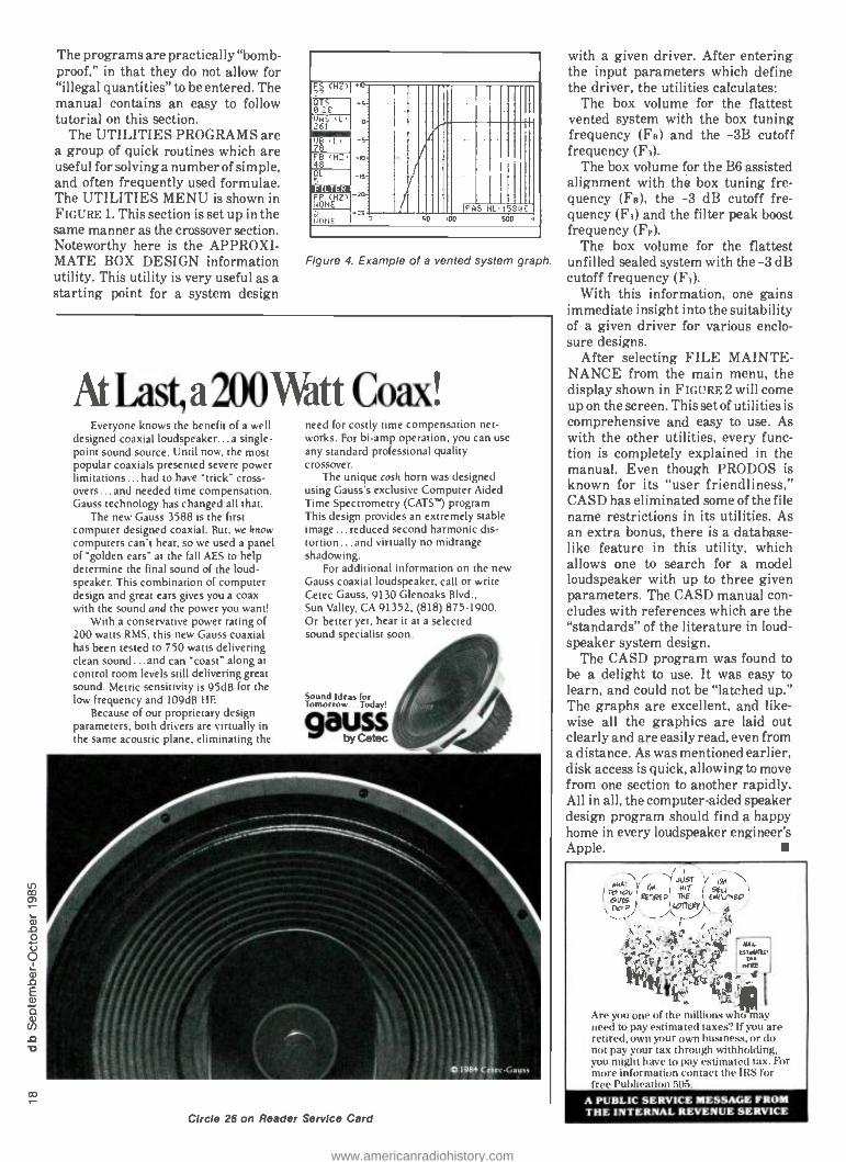
PETER HAMMAR
Audio Engineering Special! Video recording for audio engineers? Read on to find out who is actually the `father" of video recording.
A i i FOR- VIDEO" has become a major development
in the recording and production field during the past five years. Clearly, as a business and as an art form, audio and video are moving
closer together. However, this "new" audio -video engi- neering synergy should come as no surprise. Both spring from the same source, audio. As a close relative, audio will want to share in an important birthday that video will soon celebrate, the introduction of commercial videotape recording in 1956.
Audio can take credit for being the "father" of other recording media, including magnetic recording. In magnetics, some of the people who originally made audio tape possible in this country and abroad also contributed directly to the creation of instrumentation, data, and video tape recording.
For example, John T. Mullin, the man who introduced Ampex and Hollywood to audio magnetic recording in 1946, developed the first working videotape recorder (VTR) prototype for the Electronics Division of Bing Crosby Enterprises in 1951. Mullin used a fixed -head, longitudinal -scan multi -channel format for his video recorder. To build the machine's transport, the Crosby engineers used parts from an Ampex Model 200 audio recorder.
Crosby sold his Electronics Division to 3M in 1957, which became their Mincom Division. Mullin joined 3M with the other Crosby engineers. In a bit of video -for- audio reverse engineering, they used the closed -loop capstan technology that Mullin had first developed for Crosby video as the basis for the transport of 3M's famous "M" series of studio audio recorders.
At Ampex, video was the figurative rib taken from the body of audio. Officially, members of the Redwood City video team that developed the first commercially successful VTR were listed as employees of the Ampex Audio Division, the name given on the cover of the "Preliminary Manual" for the machine. Ampex created a separate Video Division only after the successful introduction of the VTR in 1956.
Peter !laminar is the consulting Curator the Ampex Museum of Magnetic Recording in Redwood City. CA.
You will recognize another of the many audio connections in the development of video recording, Ray Dolby of audio Noise Reduction'" fame, who became the second person to join the Ampex VTR team almost at the inception of the video project. Dolby, not yet out of school at the time he began at Ampex, made major contributions to the development of the video recording art.
Next year marks the thirtieth anniversary of the event that has affected all of us for three decades -the introduction of the world's first practical videotape
This Ampex VRX -1000 started a revolution in television production methods and programming.
recorder, the Ampex VRX -1000. It was in April of 1956 that Charles Ginsburg and his five associates unveiled their invention at simultaneous demonstrations in Chicago and Redwood City. Unlike the fixed -head Crosby, RCA, and BBC videotape recorder prototypes, the Ampex VTR was the first to use spinning heads and slow tape speeds to achieve the high writing speeds necessary for video.
The thirtieth anniversary of videotape recording
www.americanradiohistory.com

Prototype of the first commercially successful videotape recorder, the Ampex Mark Ill VTR in early 1955.
means more than one company's milestone. The event became a watershed in the history of television, creating a
new kind of program production industry in a medium dependent on live stage methods and Hollywood film techniques. Besides color video, no single technology changed television as much as the magnetic video recorder.
:Nineteen eighty -six marks the beginning of the fourth decade of change and innovation in television production. The arrival of digital audio and video, with the ability to manipulate picture and sound without generational loss, represents the greatest challenge for creative program production -and audio engineering -since tape arrived here after World War II. With audio -for -video, audio people are only now fully realizing the engineering and production opportunity that video tape created back in 1956.
Starting next year, I hope audio engineers will join their video brothers in taking note of the start of the truly remarkable technology of the VTR. The best way to mark the occasion is to renew our efforts at preserving both original television programming and the machines that recorded them. But we need your help out there in the field!
Many broadcasters and production studios have old two -inch videotapes that have been squirreled away in closets and on the bottom of tape library shelves. Some people don't realize that many of these dusty, old "quad" tapes represent rare, irreplaceable video footage showing the early days of the business.
I've met broadcasters and producers who assume that archives- somewhere, somehow -have copies of all
You really can! Wireworks Mix & Match Components Group gives you all the products you'll ever need to create your own perfect audio cabling system. And our Audio Cabling Design Kit shows you exactly how to put them all together.
Call or write today for your free Design Kit. With Wireworks you really conduit!
WIFigWor]ml Wireworks Corporation 380 Hillside Avenue, Hillside, NJ 07205
201/686 -7400 800/624 -0061
Circle 28 on Reader Service Card
:o .. . °.'
. ;, ' ENGINEERING ; : ;;
. çMAGÁZINE'. . . 4 . J
_o;0'.0.;..c. ,', o:: . , :
, -, 0.
0
ù'ea 1 0. c-
ò.::ó::: ';;. h..p .O;.p. O. : O .'
ç - O' . O. ' .
.. ,o.e. . .;ó:.-. .'o .
o: .o. 0. p.A..o, . . . .
www.americanradiohistory.com

This is the first -ever videotape recorder prototype in 1951. built for Bing Crosby.
important television and radio material. In fact, the majority of videotape masters of both national and local programming have been erased or destroyed over the years. We should help preserve these very beginnings of the industry by encouraging broadcasters and producers who have old tapes to donate them to archives for high - quality transfer to modern media, as well as for preservation of the original tapes.
The Ampex Museum of Magnetic Recording, which is not an archive, can serve as a conduit to connect the holders of early video footage with archivists around the country. The major archives can offer proper legal cover for program donors, protecting the owner of the physical media who may be holding copies of programs not originally authorized for duplication twenty or thirty years ago. The fact is, with our cavalier, throw -away attitude towards preservation in this country, much of the programming that archivists have saved was originally "bootlegged" and held by private collectors. Meanwhile, the dumpsters of certain broadcasters, networks, and producers continue to overflow with our national entertainment heritage.
Although they may not own the content, private holders of original programming who want to donate and preserve tapes and discs can easily be protected from any supposed copyright infringement involved in a donation to a non -profit archive. The major media archives can also
protect program producers, owners, and other equity holders such as actors and musicians. Much of this footage is vitally important in showing the birth and development of video tape, and simply must be preserved. We are looking for early black and white and color newscasts, network or local, and old videotaped programming from any market, large or small; any recordings of network feeds from 1957 to the early 1970s of either national news events or entertainment shows; any commercial spots, local or national, that may be sitting on a shelf somewhere. And don't forget kinescopes and old films made for TV!
Naturally, any important antique hardware and accessories, video or audio, should also be conserved for the future, if for no other reason than to be able to play back increasingly outdated video and audio recording formats.
Help us save an important part of our culture. Spread the word among your audio and video contacts about the kind of material we're looking for. When you find something, arrange for donation to the appropriate archive that will preserve the original and carefully make preservation copies. Or call me, Peter Hammar, at my office at (415) 941 -0295 or at the Ampex Museum in Redwood City, California, at (415) 367 -3127, for further reference.
Thanks to all of you, and happy birthday! N v
www.americanradiohistory.com

ao N
PETER HAMMAR and DON OSOSKE
The Birth of the German Magnetophon Tape Recorder 1928 -1945 This article is a revised version of the one that first appeared in db in March, 1982. With research assistance from German media historian Heinz Thiele, the authors have added new information to their original material obtained from sources that included BASF, Agfa, AEG -Telefunken, the German radio stations, the Deutsches Museum and retired audio engineers.
THE DEVELOPMENT OF MAGNETIC recording was not exactly an overnight event. From its intro- duction in 1898 as the Telegraphone wire recorder to the controversy of today's digital technology,
magnetic recording has gone through stormy times.
Peter Hammar is Consulting Curator for the Ampex Museum of Magnetic Recording, Redwood City, CA. Don Ososke is with the Ampex Standard Tape Laboratory.
Valdemar Poulsen, the Edision of magnetic recording, invented almost every known form of magnetic storage. His first idea, in 1896, was a magnetic version of Edison's cylinder phonograph. Poulsen spiralled piano wire around a brass cylinder, with a laterally- moving magnetic pick -up head pushed along by the rotating cylinder. Playing time was thirty seconds. By 1899, the Dane had developed magnetic recorders that used spools pulling wire past the record head at two meters per second, with a recording time of several minutes. Poulsen
www.americanradiohistory.com

also made a machine that used a steel band to record sound. He even made a magnetic disc recorder whose pick -up head moved along a spiral guide, very much like the magnetic disc video slow- motion recorders developed by Ampex and others in the 1960s. And all this before 1900!
Unfortunately, marketing people regarded Poulsen's technical breakthroughs in magnetic recording as a curiosity, a toy. In 1905 the Danish engineer sold his Telegraphone patents to the highest bidder and went on to do research in other areas of electricity, including radio transmitters.
Lee DeForest, the inventor of the modern vacuum tube, wanted to perfect magnetic recording -many of DeForest's early Audion tube diagrams used a wire recorder as the theoretical sound source. However, DeForest's efforts were frustrated by lack of cooperation from Poulsen's successor, the American Telegraphone Company.
For shipboard radio recorders in the 1920s, U.S. Navy researchers Carlson and Carpenter improved the Telegraphone with vacuum tubes, and added something new to the record circuit -AC bias. But their Navy sponsors lost interest in communications recording and the two were forced to drop the project. Had the Navy had a bit more foresight (easy for us to say today), we might have had relatively high fidelity magnetic wire recording as early as 1923. The Navy's reaction reflected an attitude that continued from Poulsen's day: magnetic recording was more a curiosity than a practical tool.
The next attempt to commercialize magnetic recording was made almost a quarter -century after Poulsen, when Curt Stille in Germany formed the Telegraph Patent Syndicate in 1927. Stille envisioned magnetic recorders for dictation, automatic telephone answering, and even music reproduction. None of the members of the
syndicate was very successful in their attempt to com- mercialize magnetic recording, although the Lorenz Company in Berlin almost succeeded.
Around 1933, under the direction of S.J. Begun (who later headed Brush Development in Cleveland), the Lorenz Company began work improving one of Curt Stille's ideas, using a steel band as the recording medium. Lorenz had enough faith in magnetic recording to design its " Stahltonband Maschine" or "steel sound machine" for use in radio stations as a transcription device. In fact, by the mid- 1930s, several European radio services, including the Germans and the British, had used steel recording on the air. Steel -band recorders had reached a quality level almost equal to the broadcast wax disc.
During the world -wide depression of the 1930s, people relied increasingly on radio at home for entertainment. For broadcasters, the Thirties was a time of tremendous growth in entertainment programming. Most radio stations used recording lathes to cut lacquer or very thick wax discs for use in time -delayed broadcasts. However, the wax discs could only be played two or three times before the grooves were worn. Also, the radio engineer could not easily edit a program recorded on a disc. The necessary disc -to -disc transfers to edit out mistakes led to high generational loss of sound quality.
Naturally then, magnetic recording on a long, thin strip of material offered the broadcaster editing and multiple- replay capabilities that he did not have with discs. But the Lorenz Company's steel -band recorder was out of date before they could get their machine to the broadcast market. Steel as a recording medium was impractical at best. You edited with solder and a welding torch. A fifty -minute reel of steel tape measured over two feet in diameter, and weighed almost 40 pounds!
The machines could even be dangerous for their operators. The English version, the Blattnerphone, used
Neumann wax disc recording lathes at Sender Hamburg in 1931. Recording lathes were the forerunners of the Magnetophon in German broadcasting. (Photo courtesy of the Norddeutscher Rundfunk Archives, Hamburg, Germany.)
www.americanradiohistory.com

The first Poulsen Telegraphone. circa 1898.
at the British Broadcasting Corporation until as late as 1950, was operated in a metal cage so that if the steel band flew off its reel during fast -forward or rewind, the engineer on duty wouldn't lose a hand, or worse.
The expense alone of solid steel tape was high enough to prompt the German radio service's chief engineer H.J. von Braunmuhl to look for an alternative to steel. There had to be a better answer to magnetic recording than steel band.
FROM STRAWS TO CIGARETTES TO MAGNETIC TAPE
In Dresden, Germany, the Universelle Company had been building cigarette manufacturing machines since the turn of the century. One of their engineering consultants in the 1920s was Fritz Pfleumer, whose previous discoveries included drinking straws made of plastic, as well as new forms of foam rubber.
One of Universelle's machines was designed to make cigarettes with a thin band of real gold around the mouthpiece. Even for 1928, using gold on cigarette mouthpieces was becoming expensive, so the company put Pfleumer to work finding a substitute for the gold. Pfleumer developed a bronze powder that he mixed with lacquer, spread on a wide, long strip of paper, and then slit into tiny pieces for gluing onto the cigarettes.
Pfleumer was somewhat of an audiophile. He liked
o good- quality radios and recording devices, and did much experimenting on his own. Of course, like most engineers,
Pfleumer knew about the wire Telegraphone and the early experiments with steel -band recording.
Around 1928, Pfleumer was in Paris on a business trip. While sitting in a cafe, he was thinking about magnetic sound recordings. He reasoned that, instead of using expensive, heavy steel tape for recording, he could use his cigarette- mouthpiece -label technique to make cheap, lightweight magnetic tape. Instead of bronze powder, iron powder could be mixed with lacquer and spread on a paper tape.
Pfleumer's combined knowledge of paper tapes from his cigarette work, and his understanding of magnetism and electro-acoustics was crucial to his success in making the world's first magnetic tape recorder. He knew, for example, that the iron particles had to be as small as possible to achieve the highest possible frequency response. For Pfleumer, the all- important binder material to glue the particles to the tape was no problem at all. He just used the same lacquer he had used for the bronze on the cigarette mouthpieces.
Pfleumer's first tape recorder, built in 1928 -29, sounded just awful: distortion, background noise, wow, and flutter. But the point was, the thing worked! One did not need a solid piece of ferrous material to record sound magnetically. The engineer described his recording tape as "a 300 -meter -long roll of the recording material which lasts twenty minutes and costs only one Mark 50 Pfennigs (about 25 cents) to make. The paper, called Pergamine, is only 0.04 mm thick." He pointed out that, with his new
www.americanradiohistory.com

Detail of the Telegraphone record /playback head. (Photo courtesy of the Deutsches Museum, Munich.)
recording system, the tape editor could trade his welding torch for a pair of scissors.
Unhappily for Fritz Pfleumer, the German patent office in 1936 denied him his 1928 patent, finding the American J.A. O'Neill's 1927 magnetic tape patent valid. As far as we know, O'Neill never did make workable magnetic tape or a recording device of any kind.
In 1929, Pfleumer took his invention from Dresden to Berlin, to sell it for development. Newspapers there ran
stories about the new recorder, after several private demonstrations. AEG ( Allgemeine Electricitaets Gesell - schaft, or "General Electric Company ") in Berlin, was Germany's second -largest electronics company, after the Siemens Company. AEG designed and manufactured professional and consumer electronic products, much as its business associate General Electric did in the United States.
At AEG in 1930, Pfleumer's first demonstration of his tape recorder, which he called a "sound paper machine," was less than convincing. His magnetic recorder, like others before it, sounded poor. However, for the first time in history, engineers and managers were far -sighted enough to see the potential for tape recordings. By 1932, AEG had signed a contract with Pfleumer to buy his patent outright and develop tape recording.
The engineers at AEG tried to make their own tape at first, according to one account, buying carbonyl iron at the corner drugstore and spreading it on paper "ticker tape." The sound they got from the tape was terrible, and they soon realized that the problems of spreading thin coats of iron -filled lacquer onto strips of paper tape were best left to a chemical concern.
THE FIRST TAPES In the early 1930s, the chief executive officer of AEG,
Herman Buecher, heard about his engineers' problem. He called his old friend in Frankfurt, Carl Bosch, who was the head of the powerful IG Farben chemical
In 1938, the German radio or "Reichsrundlunk" became the first broadcaster in the world to adopt tape as its transcription and time -delay standard. Shown are AEG Magnetophon K -4 "HTS" AC -bias models at Radio Kiel, circa 1943.
www.americanradiohistory.com

Neumann disc cutting head, in use circa 1931 at Sender Hamburg. Both wax and lacquer discs were used for the broadcast -quality recordings. (Photo courtesy of Norddeutscher Rundfunk Archives, Hamburg, Germany.)
combine, to see if the two companies could make the development of the magnetic tape recorder a joint venture. In 1932, AEG's Buecher and IG Farben's Bosch arranged for a member of the IG Farben group BASF. ( "Badische Anilin and Soda Fabrik" or "Baden Anilin [dye] and Soda Factory "), in Ludwigshafen, to begin intensive research into the problems of making good magnetic tape for the new AEG machine.
The first BASF tapes made in 1934 for the Berlin Radio Show was made of pure, powdered carbonyl iron. The iron, which looks like black dust, was mixed with lacquer and spread onto a cellulose acetate film, which was then cut into five millimeter -wide strips (6.35 mm =' /a inch) several hundred meters long. BASF's first tape had no trade name, and was simply called "IG Farben carbonyl tape." Mechanical problems with AEG's prototype Magnetophon postponed the planned 1934 unveiling of the new recording process until the Berlin Radio Show the next year.
By 1935, the researchers at BASF had progressed from carbonyl iron to iron oxide with smaller magnetic particles that resulted in better electrical performance. Today's iron oxide tapes are essentially refinements of these early BASF formulations.
Poulsen Telegraphone, complete (1899). Poulsen intended this device- record 'PB time = 30 seconds -to be an automatic telephone answering machine. (Photo courtesy of the Deutsches Museum, Munich.)
At the start of their joint venture with AEG, BASF switched from paper to a cellulose -acetate film. The early carbonyl iron tape was brittle, but much stronger than the first paper tapes. BASF's trade name for their acetate basefilm was "Cellite," so they called their new iron -oxide formula tape "Type C." Manufactured through 1942, Type C tape had a rust -colored oxide with a gray backing.
By 1943, BASF had introduced a third kind of tape. Luvitherm or "Type L," a homogeneous tape /basefilm of polyvinyl chloride. Though much stronger than the Type C acetate tape, the PVC did stretch. Type L tape was made by dumping the iron oxide into the PVC vat, and then extruding the mixture into a solid film. Because the iron oxide was mixed throughout the tape, Type L could be recorded on either side. Another IG Farben member, Agfa at Wolfen, later joined BASF in the production of
The first "ring head," invented by Eduard Schueller in 1932 at the Heinrich Hertz Institute in Berlin. Schueller ¡oined the AEG Magnetophon team in 1933, bringing with him his ring head patent. Photo courtesy of AEG - Telefunken Archives, Braun- schweig, Germany.
recording tape. In 1944 -45, American GIs invading Northern Europe found a lot of Type L tape. Both BASF and Agfa were able to steadily increase their tape production until war's end in May of 1945.
The origin of today's one -quarter inch tape width standard came from a combination of good engineering and coincidence. In 1935, just before the introduction of the first AEG /BASF recorder and tape, the companies jointly decided to widen the tape from its original 5.0 mm to 6.5 mm (just a hair over one -quarter inch). The engineers chose the wider tape for greater strength and better electrical performance. We still do not know why they chose the number 6.5 mm.
When the Allied engineers examined the captured Magnetophons and their BASF /Agfa tapes, they measured the 6.5 mm width as a quarter inch, plus or minus "a tiny bit." The 0.15 mm difference between a quarter inch and 6.5 mm was really not worth noticing. With the interruption of German tape manufacturing at the end of the war and the importation of American 3M (Scotch), Orradio (Irish), Audio Devices and other tape, the official width of magnetic tape there became 6.35 mm as well.
THE MAGNETOPHON Our thirty inches -per- second base tape speed also
originated in Germany with the Magnetophon. Until 1935, the AEG /BASF R & D team used one meter -per- second as their nominal standard tape speed. However, the recorder /reproducer suffered from poor mechanical
www.americanradiohistory.com
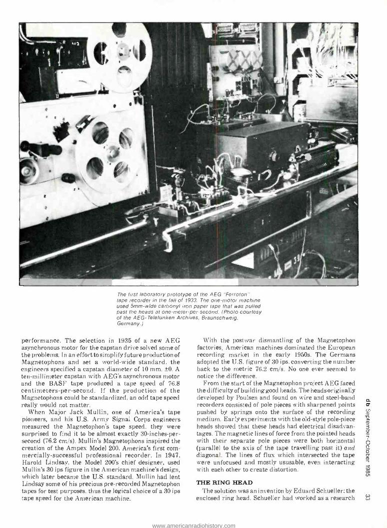
The first laboratory prototype of the AEG "Fermion tape recorder in the fall of 1933. The one -motor machine used 5mm -wide carbonyl iron paper tape that was pulled past the heads at one -meter -per- second. (Photo courtesy of the AEG - Telefunken Archives, Braunschweig. Germany.)
performance. The selection in 1935 of a new AEG asynchronous motor for the capstan drive solved some of the problems. In an effort to simplify future production of Magnetophons and set a world -wide standard, the engineers specified a capstan diameter of 10 mm, ±0. A ten -millimeter capstan with AEG's asynchronous motor and the BASF tape produced a tape speed of 76.8 centimeters -per- second. If the production of the Magnetophons could be standardized, an odd tape speed really would not matter.
When Major Jack Mullin, one of America's tape pioneers, and his U.S. Army Signal Corps engineers measured the Magnetophon's tape speed, they were surprised to find it to be almost exactly 30- inches -per- second (76.2 cm /s). Mullin's Magnetophons inspired the creation of the Ampex Model 200, America's first com- mercially- successful professional recorder. In 1947, Harold Lindsay, the Model 200's chief designer, used Mullin's 30 ips figure in the American machine's design, which later became the U.S. standard. Mullin had lent Lindsay some of his precious pre- recorded Magnetophon tapes for test purposes, thus the logical choice of a 30 ips tape speed for the American machine.
With the postwar dismantling of the Magnetophon factories, American machines dominated the European recording market in the early 1950s. The Germans adopted the U.S. figure of 30 ips, converting the number back to the metric 76.2 cm /s. No one ever seemed to notice the difference.
From the start of the Magnetophon project AEG faced the difficulty of building good heads. The heads originally developed by Poulsen and found on wire and steel -band recorders consisted of pole pieces with sharpened points pushed by springs onto the surface of the recording medium. Early experiments with the old -style pole -piece heads showed that these heads had electrical disadvan- tages. The magnetic lines of force from the pointed heads with their separate pole pieces were both horizontal (parallel to the axis of the tape travelling past it) and diagonal. The lines of flux which intersected the tape were unfocused and mostly ususable, even interacting with each other to create distortion.
THE RING HEAD The solution was an invention by Eduard Schueller: the
enclosed ring head. Schueller had worked as a research w w
www.americanradiohistory.com

assistant at the Heinrich Hertz Institute, a technical "think tank" in Berlin, and by 1932 was already experimenting with ideas of magnetic recording. Schueller found that the most important part of successful magnetic recording was the head. He decided to improve on the open pole -piece head design. The result was his experimental ring head. AEG soon offered
View of head assembly and tape path of AEG Magneto - phon K -2 (1936), the portable version of the FT -2 shown on the March db cover. (Photo courtesy of AEG - Telefunken and Ampex.)
Schueller a key position on their tape recorder develop- ment team. Schueller's ring head created the nearly ideal magnetic flux pattern necessary for better fidelity recording. The lines of flux were concentrated in their most useful direction, horizontally (in the direction of the tape).
Thanks to the AEG -Telefunken Archives, BASF, the German Radio Archives in Frankfurt, and Hans Westphal of Berlin, we have copies of the earliest recordings made on the AEG prototype recorder in 1933. On the first recordings, the frequency response limit was not more than 3 or 4 kHz, harmonic distortion was about ten percent, and the signal -to -noise ratio was quite poor. By 1935, with the introduction of AEG's first production machine, the "Magnetophon K -1," fidelity had been increased, with frequency response to beyond 5 KHz and wit less distortion.
By 1935, the Germans had three of the four necessary ingredients of modern tape recording: 1) a stable transport, which the steel band recorders such as Lorenz had; 2) good tape, which the researchers at BASF had created; and, 3) the ring head from AEG's Schueller, with its good magnetic properties and gentle treatment of fragile tape. The fourth element of magnetic hi -fi recording, good electronics, would have to wait until 1939 -40, after the Second World War had started.
From Valdemar Poulsen at the turn of the century until the late 1930's, direct -current biasing was the only method known to European engineers to reduce noise and distortion and increase frequency response. As late as 1939, the DC -bias Magnetophon sounded no better than an average 78 rpm transcription disc.
Although AEG initiated the development of the modern tape recorder, it may have been BASF that gave the machine its name. One of the names used by the engineers at AEG in 1932 -33 for their new machine was "Ferroton." At BASF, they were calling their tape
cAi "Magnetophonband" or magnetic phonograph tape. The
name stuck, and in 1935, AEG started calling the machine the "Magnetophon." The name is still used in Europe today.
Until 1945, most engineers around the world had not heard of the German tape recorder. It was the combination of DC bias and World War II that kept the Magnetophon in obscurity. Jack Mullin has said that, "Once you hear DC -bias recording, you'll never want to hear tape again!" Sir Thomas Beecham, having heard his London Philharmonic on tape in November of 1936, reportedly was so horrified by what he heard that he didn't use tape again until 1950.
In 1936, AEG sales people took their new Magnetophon to America for a secret demonstration at General Electric in Schenectady, New York. The DC -bias unit sounded so bad to the Americans that they decided that magnetic recording, at least in that form, was not practical.
The most promising market for the then -unperfected magnetic recording machine in Germany in the 1930s was the Berlin -based German radio monopoly, known as the RRG ( Reichs Rundfunk Gessellschaft or "Empire Radio Company "). The chief of the RRG engineering section, H.J. von Braunmuhl, was against using magnetic recording for broadcasting. He liked the tried - and -true wax disc recording lathes with their Neumann heads. However, the progress of the AEG and BASF engineers interested him.
Von Braunmuhl bought several DC -bias Magnetophons and put his best engineer, Walter Weber, to work to see if the machines really could be improved enough to be used on the air. Meanwhile, the people at AEG was also hard at work trying to perfect magnetic recording.
Spinning head (4 gaps, 90 degrees to tape path) of Tonschreiber "Berta'; made by AEG, Berlin, circa 1939. (Photo courtesy of AEG - Telefunken and Ampex.)
Weber at RRG had an idea of how to improve the signal - to -noise ratio. He cancelled some of the noise byaddingan inverting bridge circuit with a "dummy" record head to the record amplifier circuit. The resulting 180 -degree phase shift reduced tape noise about three dB.
AC RECORD -BIAS One day in 1940, Weber was experimenting with this
circuitry, making recordings of music and speech as well as pure tones. Weber kept logs of which recorder he had used, time of day, and what he had recorded. Later, while playing back one of the tapes, Weber found that the sound was fantastic! He was hearing true high fidelity on tape: extended frequency response, low noise, and low
www.americanradiohistory.com

The disc transcription room. Sender Hamburg, circa 1935. (Photo courtesy of the Norddeutscher Rundfunk Archives, Hamburg, Germany.)
distortion. He traced the recording back to a Magnetophon that used his new noise reduction circuit, checked that circuit, and found that it was in constant oscillation, dumping high- frequency feedback into the record circuit. Weber realized that AC record -bias was the answer to hi -fi tape recording. He spent the rest of 1940 perfecting his AC -bias discovery.
After the boss of the AEG Magnetophon lab across town heard the results of Weber's breakthrough at RRG, he went to his own researchers and said, "What in the world have you guys been doing here, sleeping? Over at RRG, they've just discovered AC bias and turned our machine into a high -fidelity recorder. We've got to get on the ball here!"
In fact, AC biasing of the record circuit was nothing new. But times were different, and engineers often missed each other's progress. Back in 1927, the U.S. Navy engineers Carlson and Carpenter, using a Telegraphone, had noticed the improvement of AC bias on wire recordings of telegraph messages. About the same time that Weber discovered AC biasing for tape recorders, Marvin Camras of the Armour Research Institute in Chicago had a similar discovery for use with his improved wire recorders. And before and during World War II, S. J. Begun of Brush Development in Cleveland applied AC bias to some of his wire and steel -band magnetic recorder designs.
With the war already in progress in Europe by 1940, it wasn't too surprising that Weber and Camras had not heard of each other's discoveries. In the late 1930s, the Japanese, under Kento Nagai, also discovered the AC- bias phenomenon on solid magnetic material.
After the war, the Allied Commissions in Germany and Japan declared all international patents of the Axis powers invalid. That left the quite advanced Armour patents as the finisher in the post -war AC bias license field.
For AEG, the beauty of Weber's discovery was that they could take their existing DC -bias design and simply add the relatively simple AC -bias circuit, while changing the record head only slightly. The playback of the DC -bias Magnetophon was quite good, although its full potential was never realized before AC -bias recording. The last production DC -bias Magnetophon had a specified frequency response of 50 Hz -6 kHz, a dynamic range of 40 dB, and harmonic distortion of 5 percent. The first AC- bias Magnetophon was rated at 40 Hz -15 kHz, with a 65 dB dynamic range, and under 3 percent distortion.
Most of the studio Magnetophons in use at the end of World War II were designed as early as 1938. The first
An AEG Magnetophon K -4, circa 1938. The DC bias version had a frequency response of 50 Hz -6 kHz. 5 percent distortion and a dynamic range of 40 dB. Once modified with Walter Weber's AC record bias, the frequency response improved to 40 Hz -15 kHz, with a 65 dB dynamic range and less than 3 percent distortion. (Photo courtesy of the AEG - Telefunken Archives, Braunschweig, Germany.)
www.americanradiohistory.com

m
production Magnetophon, the portable K -1, appeared in 1935. ( "K" stands for the German word Koffer or "portable case. ") The machine came in three cases, one for the transport, another for the electronics, and a third holding the loudspeaker. At the same time, AEG produced the cabinet "FT" series Magnetophon Fern - gesteuertes Truhe, or "remote control cabinet "). The K -2 and FT -2 were introduced in 1936. The only FT -2 in existence that we know of is now a part of the Ampex Museum of Magnetic Recording in Redwood City, California.
The K -3 and FT -3 in 1937 were followed by the final Magnetophon in the pre -1945 series, the K -4, in 1938. The K -4 is the best -known pre -1945 Magnetophon. This is the machine that Jack Mullin and his partner, San Francisco filmmaker William Palmer, used to introduce America to the new technology of hi -fi tape recording.
The 1938 K -4 had DC biasing, and after the introduc- tion of AC bias in 1941, a few early K -4s were updated. AEG also made an agreement with the RRG radio people to deliver K -4 decks built to RRG specifications incorporating the AC -bias design. The radio station console machines that Jack Mullin first saw at the Radio Frankfurt substation at Bad Nauheim in July in '45 werre special K -4 HTS ( "Handgesteuertes Truhe Speziell," or "locally- controlled special cabinet" model).
When the war started, everyone in Germany was ordered to switch over to building military products. That was as true for tape recorders as for coat buttons. AEG produced a very rugged, portable DC -bias version of the Magnetophon that they called the Tonschreiber or "sound writer." The best -known of the Tonschreibers was
Telefunken " Reisz" microphone, circa 1930, carbon - type, in solid markble housing, 50 Hz -6 kHz. (Photo courtesy of AEG- Telefunken Archives and Ampex Museum.)
the Type B, or Berta machine, which appeared in 1939 -40. Berta was unusual because the machine had an extra, spinning head which could be used to compress or expand sound for high -speed transmission of information.
An amazing fact of World War II was that no one on the Allied side seemed to have heard about the hi -fi Magnetophons until the end of the war. This ignorance is even stranger when you consider that popular German magazines and newspapers, publicly sold in neutral Switzerland, printed numerous feature articles about
German radio stations. Had the Germans classified all information about the AC -bias Magnetophons as "top secret," the Allied probably would have known about the machines before the end of 1940! As it was, they had to wait another five years.
y }r-! _
if
y ' .-. , , T
é a
.
tt"
October, 1934 Sender Hamburg remote broadcast recording on a Hamburg commuter train, using the Lorenz Steeltone machine. (Photo courtesy of the Norddeutscher Rundfunk Archives, Hamburg, Germany.)
During World War II, the Allies were sometimes confused about Hitler's location. Live -quality broadcasts of his speeches simultaneously came from all parts of Germany. The Allies suspected some sort of high -fidelity recording device, but they overlooked the fact that the Germans had an extremely advanced radio network. A complex web of high -quality land lines (10 kHz bandwidth, 600 ohm balanced line, less than 1 dB loss per 1000 km) allowed remote broadcasts from any location to any other location. In addition, time delay broadcasts had been standard procedure in Germany since the mid - 1920s. To this day, old RRG engineers are amazed and baffled to hear that Americans thought that the Magnetophons were being used to deliberately confuse the Allies as to the location of high Nazi officials.
In England between 1942 and 1944, Major Jack Mullin and others had been hearing late -night German broadcasts of live -quality orchestral music. Mullin thought that even a madman like Hitler could not compel tempermental musicians to play at three a.m. However, the audio quality of the transmissions was much better than any recording device Mullin knew. What he heard was the routine use of the Magnetophon, which had been developed as a professional and consumer entertainment device.
The Magnetophon tape recorder naturally got sucked up into the German war effort. The chief of the AEG Magnetophon lab during the war, Dr. Hans Schiesser, said that he had received specific orders from the Nazi government to work exclusively on the DC -bias military Tonschreibers for use by the army, air force and navy, and to ignore further civilian tape recorder development until after the war. However, Schiesser kept a secret set of lab notes in which he wrote of his work on high- fidelity magnetic recording, including experiments with stereo record and playback heads, which he quietly did on the side at some personal risk. For Hans Schiesser and many others at AEG and German Radio, the Magnetophon tape recorder was the exciting way into the future of high fidelity reproduction of sound.
www.americanradiohistory.com

4,QS MODERN o c5o
e ,4111 rrA r11
& MUSK
The Technology of Tomorrow... Today! \ ;; %,- ":r.-1; ;->-;. _ í ".,; ;_\, ,_,.,,: :``;;:\
_-1` = \\ - 11_
..1
Pfl2OFILES:
1
POO RECORD
Subscribe to Modern Recording & Music
-
Send MODERN RECORDING & MUSIC for:
$18.00 for 12 is Sues
Payment enclosed $
Outside U.S. adc $3.00 for each year. U.S. FUNDS ONLY.
Charge to my D Mastercharge O Visa account
My account Number is
Exp. date_J-J Name
Address
City /State Zip
Signature MODERN RECORDING 1120 Old Country Rd. Plainview, NI. 11803
O $31.00 for 24 issues $45.00 for 36 issues
L r
J www.americanradiohistory.com

PROFILE: MURRAY R. ALLEN
Universal Recording Studios
If you can't do it at Universal, it can't be done. Read on for the full story of a studio that had to do it all by itself
WHEN UNIVERSAL OPENED its doors for business almost forty years ago, it was pretty much on its own. There were no equipment rental companies. There were just a few manu-
facturers of recording equipment and they had no field support. And to make matters worse, nobody would share information with anyone else who remotely smacked of being in the same business. Unlike the two coasts, when Universal needed a special transfer it did not have another company four blocks away who specialized in such a service. Universal had to learn to do for itself. Clients would come back and tell Universal of the newest device in New York or Los Angeles. The following week Universal provided the same device in Chicago.
The one most important rule that Universal has followed throughout all of its growth is that whatever is added in the way of equipment and services must meet the highest standards of the professional audio field. Nothing has been added just for hype.
Today Universal lists among its clients every other recording studio in Chicago and a couple of majors in New York and LA, just about every major advertising agency in the world, all of the big five record companies and most of the major motion picture companies in Hollywood. Also, let's not forget the blue chip corpora- tions and publishers. It is impossible to turn on prime time TV and not hear something recorded at Universal.
Universal is comprised of two film mixing theaters, three 48 -track music scoring and video post -production studios, two 16 -track music scoring and video post production studios, one 8 -track media studio, two 4 -track media studios, four film /video transfer suites, one optical
Murray R. Allen is the president of Universal Recording Studios. Murray Allen.
www.americanradiohistory.com

Recording PBS radio theatre is studio C.
transfer suite and three tape copy rooms. Also, a search and storage room for music libraries and a zillion sound effects. Universal has enough room in its tape vaults to store over 25,000 sessions and they mean 24 -track sessions.
Universal has also been a leader in the area of digital recording. After six years of experience in this field it proudly boasts of owning six digital recorders encompas- sing 32 -track digital machines, 4 -track digital machines and 2 -track digital machines from such manufacturers as 3M, Sony and Mitsubishi. In fact, Universal was the first studio in the world to develop a system whereby a digital recorder could talk to a Necam computer.
Let's take Universal apart piece by piece to see why it's the ultimate as a one stop recording studio. Let's start with Studio A.
This is the largest room in the midwest. It measures 68,000 cubic feet, and can handle the Chicago Symphony Orchestra comfortably. Studio A is a 48 -track music scoring /video post production room. This room has been used to score the Blues Brothers Film, record stars from Stevie Wonder to The Police, Grammy winning albums plus many Clio winning spots. Phil Ramone has been quoted as saying, "If the walls of studio A could talk, we would hear the history of modern music."
The console is a Neve 8048 with Necam. The digital tape machines are a 3M 32- track, a 3M 4 -track and a Mitsubishi X -80. The analog tape machines include a pair of MCI 24 -track recorders, an Ampex 102 and an Ampex 104. Video -wise there is a JVC 8250 with all machines looking at a BTX Softtouch System. There are five monitor systems available on a moment's notice. There are two live room chambers, two EMT 140 -S plates and a Lexicon 224x with Larc for echo. In addition, there are
about seventy -five additional pieces of processing equipment from Pultecs to Quantecs to help get any sound you may desire. Musical instruments include a Bosen- dorfer 9.5 -ft. Imperial Grand piano with a 97 key keyboard, a Fender Rhodes, a celeste, a Hammond B -3, a tack piano, several drum sets to choose from and a complete set of tympanies. Universal probably has the greatest collection of microphones anywhere. You can find almost any microphone ever made from several C- 12s and U -47s through today's 414s. Of course, any synthesizer you might want is available as well as 16mm and 35mm full screen film projection.
Now for studio B. This studio, like studio A, is a 48- track music scoring /video post -production room. Artists from Nat King Cole to Prince and from Sir George Solti to Little Wally and his Polka Kings have recorded in studio B. Let's not forget Dizzy Gillespie. The console is an SSL 6000 Series with total recall. It has the same digital and analog machine components as studio A. It also has a dedicated JVC 8250 /BTX Softtouch package similar to studio A. For echo there's a live room chamber, a stereo EMT plate and another Lexicon 224. The piano is a 7 -ft. Steinway. You have the choice of one of their five Fender Rhodes or many drum kits to fill out your instrument needs. Of course, there are all those microphones and processors as well as 16mm and 35mm full screen projection.
The Backroom is another 48 -track music scoring /video post- production room. One of the 24 -track machines in this room is convertible to a 16 -track recorder, a video quad lay back machine or a C- format lay back machine. However, Universal likes to perform its C- format layback in a professional manner, so it also has a C- format video machine in this studio. There is also a dedicated
www.americanradiohistory.com

BTX Softtouch /JVC 8250 video system. As this studio is used a great deal for overdubs and foreign language recording the studio cue has 6 channels and a stereo mixer at every earphone position. The console is an MCI 628. Other tape machines include Ampex 102s and an Otani 4- track. This studio also has its own Steinway 7 -ft, piano. For echo, there are EMT plates as well as its own Lexicon 224. Of course, all of the above mentioned
Rock set -up in studio A.
goodies from studio A and B are available too. Various artists from Gary Coleman to Ray Parker Jr. have recorded in the Backroom.
Now to the film division. Theaters one and two are placed back to back separated
by a large machine room. Both theaters have multitrack ADM consoles with total machine control at the console. This includes start /stop and high speed shuttle controls, advance /retard controls, all in /out record functions, and BTX Softtouch controls for non -sprocket /video synchro- nization. Both theaters have 35mm, 16mm and full screen video projection. The consoles have 4 -band equalizers on every fader as well as programmable graphic equalizers. Naturally, each theater has echo, several digital delays, and digital reverb systems designed by Lexicon. You will also find dip filters and compressors in both theaters as well as JVC 8250 video recorders.
The machine room contains twenty -seven Magna Tech high speed dubbers and recorders. These machines have a total of fifty -seven heads giving the client the option of 6- track, 4- track, 3- track, 2 -track and /or monaural play /record. If so required, Universal can give the producer seven 4 -track recorder /dubbers at the same time. These machines run at 24 frames, 25 frames and 30 frames per second. They are capable of looking at 50 Hz, 60 Hz or 59.94 Hz as a sync source. In the 16mm mode they have both edge and center track. Naturally, Dolby units are available -on special request, up to 96 channels worth.
Universal also offers computerized ADR using both 35mm, 16mm film, and /or video. Another popular format is the synchronization of digital non -sprocket equipment with the film dubbers either for playback or record. The final master mix can be on film, audio, digital, U -matcc or C- format video. By the way, about fifty percent of the national commercials aired on the 1984 Olympics were mixed in these theaters.
The four film transfer rooms are capable of handling
480 different combinations from 50 Hz, 60 Hz, stereo Nagra center -track to standard or drop frame time code looking at either line frequency, 60 Hz crystal or 59.94 Hz house sync to 25 fps, 24 fps to 30 fps be it 35mm 6- track, 4- track, 3- track, mono or 16mm edge or center or both.
The optical transfer facilities are the only full time operation of its kind in Chicago.
Studio C is a 16 -track music studio. The console is designed and built by Universal's staff. The recorders are a Teac 16- track, an Ampex 800 and an Ampex 102. For echo there is a live room chamber and an EMT plate, plus its own package of peripheral gear. Studio C has access to all of the company's other goodies. The piano is, of course, another 7 -ft. Steinway. This Studio has recorded from comedians like Imogene Coca to actors such as Robert Duvall.
Another 16 -track studio is called Universal Prudential. This room is a media /video post production suite. It can handle up to eight voices at one time. The console is custom designed along the lines of a Quad Eight. Along with four Ampex 2 -track and full -track machines there is a Teac 16 -track recorder. The echo is an EMT 140 -S. The video package includes the JVC /BTX Softtouch System found all around the company. Naturally there is a total peripheral package to support this type of recording. From Louis Nye to William Conrad, this studio has recorded some of the major voices in the industry today.
In addition, there are three 4- track /8 -track voice studios used for slide film and radio production. Each of these rooms has four machines, custom consoles, and a peripheral package to match its needs. For a complete list of artists that have used these, as well as the rest of
Large scoring date in progress at Universal's studio A.
Universal's studios, write to Universal Recording at 46 E. Walton Pl., Chicago, Il 60611. They probably will send you one of their award winning brochures.
But equipment isn't everything. The people who work at Universal are very special too. Among the 37 persons employed at Universal you can find someone that will speak just about any foreign language that you will hear in the recording business. Eighteen are accomplished musicians and most are college graduates. The tech department has four men with B.S.E.E. degrees. The number of gold records, Clios and other awards won by people on Universal's staff numbers into the hundreds.
If you can't make it to the AES, NAB, or SMPTE con- ventions, drop by Universal. It's probably the next best thing.
www.americanradiohistory.com

Master Sound at Movie Studio
SAMMY CAINE
Master Sound Astoria is located in the heart of Kaufman Astoria Studios and spent over one year in the planning at a cost of over three million dollars. We bet you would like to know a bit more about the place...
Main building at Kaufman Astoria Studios.
ivi\STER SOUND ASTORIA (MSA) is located in the heart of Kaufman Astoria Studios, a four- teen -acre complex that has been declared a National Landmark. The complex houses
eight sound stages totalling more than 65,000 square feet, a pair of radio stations, and an array of production offices including producers, directors, writers, editors, record companies, and suppliers. It can be the center of a con- tinuous pre -production, shooting, and post -production
Sammy Caine is the technical editor of db Magazine as well as a freelance recording engineer.
schedule for feature films, television productions, com- mercials, teleconferencing, cable TV, videodisc produc- tion, satellite distribution, closed circuit TV, corporate communications, and other audiovisuals.
The studio itself occupies over 14,000 square feet at the center of all this, is ready for film scoring, and is large enough to accommodate a full orchestra. It is hard wired to three of the sound stages (stage E, 26,040 sq. ft.; stage G; and stage H, at 12,000 sq. ft. each), with 100 mic inputs and audio /video monitor communications for each. This will allow major live music videos to be shot and gives the ability to sync high quality audio with any film or television scene. A
www.americanradiohistory.com

STUDIO DESIGN The abilities of Master Sound are virtually limitless.
This is due to the huge amount of pre -planning by Ben Rizzi and Maxine Chrein who originally started Master Sound in Franklin Square, NY in 1971. The studio initially opened as a small 4 -track studio but it rapidly grew into a major 48- track, state -of- the -art facility, handling all types of recordings. The studio represents over a year of planning and three million dollars in design and construction costs. Computers were used to assist in the design of such things as the air conditioning system which is capable of fifteen -tons and is totally silent.
The studio itself was once used by the Army Corp of Engineers for various recordings. The old control room was isolated from the studio by 1,500 lb. doors, but it was too small for the control room planned by MSA. So the obvious choice was to build a new control room and use the old one as an isolation booth. The new control room was built to exacting specifications and utilizes walls consisting of industrial particle board (weighing 100 lbs. per 4 x 8 sheet) and Celotex which is then sealed in lead and faced with neoprine, with a % -in. layer of sheet rock on top of all that. The design was unique in that the room was planned to be able to reproduce any sound the studio itself is capable of. .
The studio's walls are based on 2 x 6 heavy gauge steel studs with % -in. sheet rock, 1-in. core board, a layer of lead and then another layer of % -in. sheet rock. This design was necessary since the studio is located directly below a large sound stage. We all know what would happen if they were filming a quiet love scene on the sound stage while the Who or some other loud rockers were laying down rhythm tracks at Master Sound.
The studio and control rooms are completely airtight
and utilize double floating ceiling construction with industrial particle board. Invariably, with this type of construction, problems came up when trying to design something as simple as a pipe to run the sprinkler heads into the control room. Special lubricating grommets had to be custom fabricated to allow the heads to extend into the ceiling without breaking when the floating ceiling moves up and down with the changing air pressure in the room.
EQUIPMENT A Trident console sits on a sand -filled platform that is
flanked by a pair of enclosed (sliding glass doors) alcoves for the multitrack tape machines (which are currently a pair of Ampex ATR -124s, but 48 -track digital is coming soon to MSA). The room design uses RPG Diffusors custom designed by Peter D'Antonio to produce a very even front end. (See accompanying article by Peter D'Antonio.) Room designers Ben Rizzi and acoustician Charles Bilello (who is an accredited LEDE'" designer by Syn -aud -Con) designed the room with the aid of the Tecron TEF Computer.
The JBL 4435 monitors are mounted above the control room glass with a McIntosh MC 2500 amplifier mounted directly beside each. The amps are strapped for 1000 watts per channel and are connected to the monitors using a short run of Monster Cable. They are isolated from the wall by being mounted on floating mounts to further enhance their sound. The monitors are not aimed down at the console as many studio control rooms are set up. Instead, they are aimed in a horizontal plane toward the rear of the control room. According to Ben Rizzi, this is the proper way to mount the monitors, and upon listening to them, you'll know he's right. Instead of feeling
Studio under construction
www.americanradiohistory.com

as though the sound is hitting you at high listening levels, you get more of a perception of actually hearing it, as the sound seems to "glide" over you.
The studio features "absolute polarity." Regardless of the amount of signal processing equipment a mic input goes through, a positive wave will be a positive wave from the microphone all the way down to the tape machine. There is also a full pipe grid system in the studio for video lighting to enable any type of live shoots. There will also be an audio post -production suite for video and film as well as SMPTE equipped rooms for computer mixing and video post production.
The studio also features a full array of outboard signal processing equipment including an EMT 251 digital reverb system and a True Star grounding system with all the equipment grounds going to a grounding buss on the console.
MORE ON THE KAUFMAN ASTORIA STUDIOS (KAS)
During the start of the American film industry, the complex was Paramount Picture's East Coast Studios. It was originally opened in 1920 and was used to film movies by such stars as Gloria Swanson, Claudette Colbert, W.C. Fields, Rudolph Valentino and the Marx Brothers. Later it was used by the US Signal Corps as the Army Pictorial Center from 1942 -1970. After briefly being used by the City University of New York, the buildings were
left to decay and be defaced by vandals. Then real estate developer George S. Kaufman put together a financial package to rehabilitate and expand the production facilities. KAS contains the first new sound stages to be built from scratch in over 50 years in the New York area. During the construction of two studios -each 12,000 square feet -500 construction jobs were created to aid the ailing New York unemployment rate. Twenty -three million dollars went into the construction of the new sound stages, a three story support building, and the rehabilitation of the existing sound stages. In addition, extensive support facilities such as production offices, hair and make -up rooms, dressing rooms, wardrobe, carpentry, scenery and prop shops were also rebuilt or built from scratch where necessary.
TAKEOVER FROM THE GOVERNMENT The original parcel of land was 5.3 acres when it was
taken over from the Federal Government by Kaufman in 1977. It has grown to over fourteen acres with more than seventy -five in -house field related tenants. The complex employs about 400 people, but this varies as the jobs go in and out.
Since the complex reopened in 1977, countless feature films and hundreds of commercials have been shot there. The first feature film was "The Wiz" in 1977 and it was followed by a string of movies including "The Warriors,"
MSA control room.
www.americanradiohistory.com

RPG Diffusor system in MSA control room.
"Hair," "All That Jazz," "Fort Apache, The Bronx," "Eyewitness," "The World According to Garp," "The Verdict," "The Cotton Club," "Turk 182," and "Death of a Salesman." These were all full budget films, and contributed millions and millions of dollars to a local economy that really needed the boost.
The expansion also includes the addition of two radio stations owned .by Doubleday Broadcasting. WHN -AM (the country's number one country station) and WAPP- FM are moving their studios to the complex and are scheduled to begin broadcasting from their spot in the complex -which is adjacent to Master Sound Astoria - by the end of this year. There is already talk of collaboration between MSA and the radio stations for promotions and productions to-benefit both.
REHEARSING AT KAS STAGE H Even without MSA, KAS is a center for music
production and rehearsals. In recent months many recording acts have rehearsed at KAS before going on tour. The Beach Boys used the 12,000 square foot stage H before their recent 50 -city national tour. They took advantage of the 31 -foot grid height to test a unique, new lighting truss design and a new set design for the tour. The Power Station also utilized the stage as a rehearsal studio before their current national tour because they needed a large space with a high power capability. Also using the studio for rehearsal was Roger Waters (lead singer of Pink Floyd) to prepare for his international
4 tour.
...There is a better way to sell your equipment - in classified or display advertisements! Call us today for an advertising rate package.
(516) 433 -6530
www.americanradiohistory.com

MICROPHONES! At long last. all the questions you ever asked tele problems you ever grappled with ... are aiswered clearly and definitively.,
M Hqndh0ok
In 256 fact -filled pages, liberally sprinkled with over 500 Illuminating photographs, drawings amid diagrams, John Eargle covers virtually every practical aspect of micro- phone design and usage.
Completely u o to date, this vital new handbook is
a must for any professional whose work involves microphores Here a'e just a few of the topi :s that are thorou:h y covered:
Directional characteristics -the basic patterns. Using patterns effectively. Microphone sensitivity ratings. Remote powering of capacitors. Proximity and distance effects. Multi- microphone interference problems. Stereo microphone techniques. Speech and music reinforcement. Studio microphone techniques. Microphone accessories. And much, much more!
THE MICROPHONE HANDBOOK. You'll find yourself reaching for it every time a
new or unusual problem crops up. Order your copy now!
JOHN EARGLE, noted author, lecturer and audio expert, is utce- president .
market planning for James B. Lansing Sound. He has also served as chief engineer with Mercury Records, and is a
member of SMPTE, IEEE and AES, for which he served as
president in 1974 -75 Listed in Engineers of Distinction, he has over 30 published articles and record reviews to his credit, and is the author of another important book. Sound Recording.
Microphone
HandboOk e
r
$31.95
r ELAR PUBLISHING CO., INC. 1120 Old Country Road, Plainview, NY 1/803
Yes! Please send copies of The Micro- phone Handbook u( $31.95 per copy. New York State residents add appropriate sales tax.)
-1 Payment enclosed. Or charge my MasterCard Visa
Acct. # Exp. Date
Name tplease print)
Address
City
State /Zip
Signature
Outside U.S.A. add 52.00 for postage. Checks must be in U.S. `unds drawn nn a U S bank If you aren't completely satisfied, you may return your copy In good condition within 15 days for full refund or credit.
www.americanradiohistory.com

DR. PETER D'ANTONIO
The Reflection Phase Grating Acoustical Diffusor: Diffuse It Or Lose It In our article on Master Sound, mention is made of a reflection control system used in the control room. This article details the concepts behind the RPG Diffusor system as used at Master Sound and elsewhere.
ARCHITECTURAL ACOUSTIC DESIGNERS and con- tractors are called upon to create or modify a wide variety of different listening and perform- ing environments. To achieve the desired acous-
tical characteristics, designers only have three ingredi- ents at their disposal- namely, absorption, reflection and diffusion. We are all familiar with absorptive materials like fiberglass, foam or diaphramatic panels, which absorb or attenuate sound over a particular frequency range. Reflective surfaces, like flat or curved panels which scatter sound specularly, as light is reflected from a mirror, are also very common. But what are diffusive surfaces, and why are they so important in room acoustics?
Sound diffusion refers to the spatial and temporal distribution of the backscattered acoustical energy from a reflecting surface. A good diffusor distributes this backscattered sound over an appreciable time period (three milliseconds or more) and over a wide angular range. In addition, the energy of the spatially diffused
Dr. D'Antonio is the president of RPG Diffusor Systems, Inc.
sound (polar energy response) is relatively constant for a broad range of frequencies. Consequently, in evaluating potential sound diffusing surfaces one should consider the steady -state energy response versus time. frequency and directivity, over a broad frequency range. For example, a cylindrical surface provides excellent spatial diffusion, but the temporal distribution is poor and the polar energy response bandwidth is limited. Many surface treatments, such as cylindrical columns, irregular geometrical shapes and distributed absorption, have been utilized to try to improve sound diffusion. While these conventional approaches provide useful scattering, none possesses all of the characteristics necessary for good diffusion.
Research at RPG Diffusor Systems on innovative archi- tectural acoustic products has led to the development of a diffusive surface which offers a unique approach to providing sound diffusion using a reflection phase grating (RPG). The RPG consists of a periodic grouping of an array of wells of equal width but different depths, separated by thin dividers. The depths are based on mathematical number -theory sequences suggested by
www.americanradiohistory.com
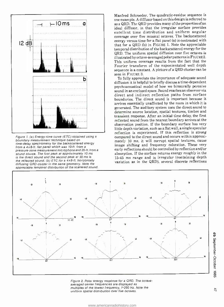
Figure 1. (a) Energy -time curve (ETC) obtained using a
boundary measurement technique based on time -delay spectrometry for the backscattered energy from a 4x8 -ft. flat panel which was 10 -ft. from a
pressure -zone measurement microphone and 20-ft. from a
sound source. The first peak at approximately 10 ms is the direct sound and the second peak at 30 ms is the reflected sound. (b) ETC for a 4x8 -ft. horizontally diffusing ORD cluster in the same geometry. Note the appreciable temporal distribution of the scattered sound.
Manfred Schroeder. The quadratic- residue sequence is
one example. A diffusor based on this design is referred to
as a QRD. The QRD provides many of the properties of an ideal diffusor, in that the irregular surface provides excellent time distribution and uniform angular coverage over five musical octaves. The backscattered energy versus time for a flat panel (a) is contrasted with that for a QRD (b) in FIGURE 1. Note the appreciable temporal distribution of the backscattered energy for the QRD. The uniform spatial diffusion over five octaves is illustrated by octave-averaged polar patterns in FIGURE2. This uniform coverage results from the fact that the Fourier transform of the exponientated well depth sequence is a constant. A picture of a QRD cluster can be seen in FIGURE 3.
To fully appreciate the importance of adequate sound diffusion it is helpful to briefly discuss a time -dependent psychoacoustical model of how we binaurally perceive sound in an enclosed space. Sound reaches an observer via direct and indirect reflection paths from surface boundaries. The direct sound is important because it arrives essentially unaffected by the room in which it is
generated. The auditory system uses the direct sound to determine source location, spatial textures, timbre and transient response. After an initial time delay, the first reflected sound from the nearest boundary arrives at the observation position. If the boundary surface has very little depth variation, such as a flat wall, a single specular reflection is experienced. If this reflection is strong compared to the direct sound and occurs within approxi- mately 10 ms, it will corrupt spatial textures, cause image shifting and frequency coloration. These very early reflections should be controlled by reflection and /or absorption. If the surface returns energy roughly in the 15 -45 ms range and is irregular (containing depth variation as in the QRD), several discrete reflections
Figure 2. Polar energy response for a QRD. The octave - averaged center frequencies are displayed as multiples of the lowest frequency, f =250 Hz. Note the uniform spatial distribution over five octaves.
www.americanradiohistory.com

Figure 3. Cluster of two horizontally diffusing (lower units with vertical wells) 24x48x 16 -in. ORD -4311 units and one vertically diffusing (upper unit with horizontal wells) 24 x 48 x16-in. model ORD -1911.
closely spaced in time will be experienced by the observer. the temporal and spatial diffusion provided by the QRD reduces the steady -state energy, thereby minimizing frequency coloration and false localization. The temporal fusion of the direct and diffuse early sound produces a louder, fuller, clearer and more spatially diffuse sound.
In addition to reverberation and spectral balance, research over the past twenty years has indicated that lateral sound diffusion is a significant parameter which increases listener preference, by decreasing the similarity of sound reaching each ear. This suggests that the directional properties of early reflections as well as their temporal distribution are important in enhancing the spatial impression and stereophonic perception of music. The RPG is uniquely suited to providing this lateral energy. The backscattered sound from a one - dimensional laterally diffusing (vertical wells) RPG is concentrated into a hemidisk whose height is proportional to the projected well length of the modular cluster. This hemidisk can be conveniently directed by orienting the diffusor or the source.
The RPG represents a new architectural acoustic ingredient which was formerly unavailable. Designers and contractors now have at their disposal modular and attractive room treatment which is easy to install, has been proven effective and is readily available in almost any natural wood or laminate finish. The RPG can be used to enhance the acoustics of any critical listening or performing environment.
Figure 4. Rear view of control room at Teleimage, Dallas, TX.
www.americanradiohistory.com

The RPG is finding widespread application in control monitoring rooms for audio, radio, stereo TV, audio -for- video, film and editing. The accurate perception of spatial textures over loudspeakers in listening environments ranging from control rooms to the home is becoming increasingly important with the advent of stereo TV. Ambisonics. Holophonics and Spatial Reverberation. Psychoacoustical experiments using the Listening Environment Diagnostic Recording, developed by Douglas Jones, have demonstrated the importance of sound diffusion and the control of very early reflections. A new design for a reference monitoring room has been developed at RPG Diffusor Systems for the faithful perception of spatial textures, and the accurate evaluation of frequency balance, signal processing and reverberation. This design incorporates a reflection -free zone, RFZ, in the front of the room, which minimizes the speaker- boundary- interference over a large volume including the entire console and mix position, and RPG diffusors in the rear of the room, to provide a dense diffuse lateral sound field, which permits critical listening anywhere in the rear of the room. The RFZ /RPG design has been utilized in many new installations including Teleimage, Dallas, TX, designed by Russell E. Berger of Joiner -Pelton -Rose (F lima 4) and Master Sound Astoria, Astoria, NY, designed by Charles Bilello (cover photo).
The need for effective diffusion in recording studios is
becoming increasingly more important with the use of digital recording. We are presently enjoying a renais- sance in studios with good natural acoustics. The RPG can be used in ceilings and /or walls or as moveable partitions to provide variable early energy to complement variable reverberation designs. The RPG can be used to increase the apparent size of small rooms and hence can be effectively utilized in mobile studios and voiceover/ announce booths.
The RPG can be employed in auditoriums, churches. performing arts facilities, theatres and rehearsal spaces as modular suspended ceiling panels and /or wall systems to provide significant early lateral energy and control slap and flutter echoes, without introducing absorption. Listeners in the audience benefit from more uniform coverage and an enhanced stereophonic experience, with precise imaging, spatial textures and "clarity." The RPG has also been used as an orchestral /choir shell to provide the necessary early reflection pattern which afford a heightened sense of ensemble for performers. Low cost RPG licensed concrete wall forming can significantly reduce the cost of indoor and outdoor venues.
Since quality and intelligibility are becoming important in business conference rooms and audio /visual multi -purpose rooms. The RPG can also be used in conjunction with PA systems in clubs to assist in providing uniform coverage and minimizing room interference.
The RPG is finding extensive application in the audio industry. These are a few installations using the systems:
Acorn Sound Recorders -Oak Ridge Boys, Henderson- ville, TN;
Chicago Recording Company, Chicago, IL; Mastermix, Nashville, TN; Master Sound Astoria, Astoria. NY; Medallion Film Labs, Toronto, Canada; NBC, Burbank, CA and Brooklyn, NY: New Age Sight & Sound. Atlanta. GA: Otis Conner Productions. Dallas, TX:
Polygram, New York, NY; RCA. New York, NY: Jimmy Swaggart Ministries, Baton Rouge. LA; Streeterville Studios, Chicago. IL; Teleimage, Dallas, TX: TRC, Indianapolis. IN; WFMT Radio. Chicago, IL. For more information contact RPG Diffusor Systems,
Inc., 12003 Wimbleton Street, Largo, MD 20772; (301)- 249 -5647.
' "RPG, QRD and RFZ are trademarks of RPG Diffusor Systems. Inc.
REFERENCES 1. P. D'Antonio and J. H. Konnert, "The Reflection Phase Grat-
ing Diffusor: Design Theory and Application." J. Audio Eng. Soc.. Vol. 32, No. 4, pp. 228 -238 (April 1984).
2. Synergetic Audio Concepts Tech Topics, Vol. 11. No. 7
(Spring 1984). 3. Synergetic Audio Concepts Newsletter. Vol. 11, No. 32,
pp. 14 -17 (Winter 1984). I. P. D'Antonio and J. Konnert, "The RPG Reflection Phase
Grating Diffusor," Mix Magazine. Vol. 8, No. 8, pp. 74 -76 (August 1984).
5. P. D'Antonio, J.H. Konnert and F. Becker, "The RPG Re- flection Phase Grating Diffusors: Experimental Measure- ments." 76th AES Convention, New York (October .1984), Preprint No. 2158.
6. P. D'Antonio and J. H. Konnert, "The RPG Reflection Phase Grating Acoustical Diffusor: Applications," 76th AES Convention, New York (October 1984). Preprint No. 2156.
7. P. D'Antonio and J. H. Konnert. "The RFZ /RPG Approach To Control Room Monitoring," 76th AES Convention, New York (October 1984), Preprint No. 2157.
8. Synergetic Audio Concepts Tech Topics, Vol. 12, No. 1 (Fall 1984).
9. R. Todrank, "Incorporating Reflection Phase Grating Diffusors on the Rear Wall to Enhance Spatial Imaging and Stereo Ambience," Recording Engineer /Producer, Vol. 15. No. 6, pp. 122 -125 (December 1984).
10. P. D'Antonio and J. H. Konnert, "The Role of Reflection Phase Grating Diffusors in Critical Listening and Perform- ing Environments," 78th AES Convention, Anaheim (May 1985), Preprint No. 2255.
11. P. D'Antonio. John Konnert and Russell E. Berger, "Control Room Design Utilizing a Reflection Free Zone and Reflec- tion Phase Grating Diffusors: A Case Study." 78th AES Convention, Anaheim (May 1985).
12. B. Comer, Mix Magazine, Vol. 9. No. 5, pp. 126 -130 (May 1985).
13. J. McCarthy, Mix Magazine, Vol. 9. No. 8, pp: 20 -25 (August 1985).
14. P. D'Antonio, "The Reflection Phase Grating Acoustical Diffusor." Innovations in Sound. Pro Sound News (Sep- tember 1985).
15. M.R. Schroeder. "Number Theory in Science and Com- munication. with Applications in Cryptography. Physics, Digital Information and Self- Similarity," Springer, New York, 1985.
16. M. R. Schroeder. "Progress in Architectural Acoustics and Artificial Reverberation: Concert Hall Acoustics and Number Theory," J. Audio Eng. Soc., Vol. 32, No. 4, pp. 194- 203 (April 1984).
www.americanradiohistory.com

11Jf(1TE PREFERABLY ALIVE ! ! !
We are looking for you out there, you who may have developed computer programs or devices for the audio industry.
If you are a manufacturer who has developed a new idea or method of testing or producing using a computer -tell us! We want your idea in our new computer column.
If you are an audio engineer who has come up with an innovative way to use a computer in the recording, broadcast
or sound reinforcement field -tell us! We want you to tell us and the world about it.
If you are a programmer or someone who has a special knowledge of computers in audio -tell us! We'll let everyone know about it.
This is your opportunity to tell the world about your brainchild -your innovations -your genius!
Tell us -here at db-The Sound Engineering Magazine.
Sagamore Publishing Co. 1120 Old Country Road Plainview, NY. 11803 (516) 433 -6530
www.americanradiohistory.com

e ? Sound Engineering Magazine
for Recording Engineers #1 for Broadcast Engineers # 1 for Sound Contracting Engineers
You can receive one year o (six issues) for $12.00.*
Name .__ _
Address
db
City /State /Zip
Charge to my Mastercharge El Visa account My account number is - -
Expiration Date
Signature
This rate limited to the USA and its possessions; for Canada and Mexico, add $1.00; all others add $10.00. Checks must be drawn on a U.S. bank.
Lfor new subscribers only.
www.americanradiohistory.com

New Products
N
BOURBAKI WONDER SOFTWARE
Bourbaki Inc. may be a new name to audio pros, but if you, like us, are using computers (especially IBM PCs and compatibles) then this may well be a company you ought to know. Those of us that have wrestled with the stubbornness of MS -DOS and our inability to do much with it except copy or format diskettes, will wel- come an exceptional program called simply 1 dir (WONDER). What this
SOUND TECHNOLOGY AUDIO TEST EQUIPMENT
The Sound Technology 3000 Series audio and transmission test system is designed for benchtop, field service. production line and remote testing. The 3000 Series consists of two separate components: the 3100A Generator and the 3200A Analyzer. Both microprocessor -based instru- ments feature front panel program- mability which allows storage of extensive automated test sequences. Both also feature the ability to com- municate test data through the audio line being tested because of an exclusive Frequency Shift Key (FSK) technique. This feature allows un- manned, automated remote trans- mission line testing (such as proof -of- performances for microwave, satel- lite, or telephone lines) without the need for external computers and modems. Test results are achieved in less than sixty seconds and may be graphed on a standard printer or plotter. If desired, the 3000 Series functions may also be controlled via RS -232C or GPIB (IEEE -488) com- munications ports. The two -channel, electronically -balanced and floating 3100A Generator outputs sinewaves, squarewaves, IMD, toneburst and sinestep waveforms. The two-channel companion 3200A Analyzer will measure level, noise, frequency,
program does is take the MS -DOS directory and envelope it in an attractive (and colorful if you have a color monitor) display. Once so enveloped, the program permits you to copy, delete, change names, and dozens of other things to files, with an ease that you won't believe until you have the program. You may need to partly strip down your MS -DOS disk to its essentials for boot -up, before you install 1 dir. It requires a great deal of disk space if you want the
entire program with its help routines, or you can get the basic program onto disk with only about 60k used. How- ever, once it is booted up and running, you can take out the diskette and substitute any others, since 1 dr entirely resides in RAM while the computer is on. Mfr: Bourbaki, Inc. Price: $95. for IBM compatible disk
with manual.
Circle 9 on Reader Service Card
harmonic distortion, intermodula- tion distortion, phase error, channel separation and quantizing noise (digital data). Output levels range from +30 to -90 dBm; system residual distortion is less than 0.001 %; mea- surement speed is 500 milliseconds for distortion and 150 milliseconds for level above 50 Hz. Both compo- nents have extensive RF shielding (utilizing fiber-optic technology) and are available as separately housed
portable instruments or in a single rack mounting or stand -alone chassis. Mfr: Sound Technology Price: 3000A (Single Mainframe) -
$8, 950; 3100A Audio Generator-
3,950; 3200A Audio Analyzer -
5,350.
Circle 29 on Reader Service Card
www.americanradiohistory.com

SPEAKER DESIGN SOFTWARE
F5 (HZ)
::: o
111111111111111 II
280
'lilII.illII ggIII ir z' GL66 i 11111.111111
Mil 1111 . n K HONE o i m m
S (H2) 5
K
Vf(S! iL) Ú u
?:gL l
g tHZS ' 'ir.[ta i m m m K
EMT DIGITAL REVERBERATION SYSTEM
The EMT 252 Digital Reverbera- tion System is the latest development from EMT. The system provides very natural reverberation through digital processing using high -resolution 16- bit analog /digital conversions and 32 kHz sampling. In addition to generating excellent reverberation effects, the EMT unit provides three delay -based effects: straight delay, loop echo and chorusing effects. The reverberation program provides up to nine individual reflections before reverberant signal, time and ampli- tude of the reflections are adjustable individually, with frequency re- sponse of the system adjustable in four separate bands. Reverberation is generated using the entire audio frequency range of the source signal, resulting in very natural sounding output. Four reverberation algo- rithms are implemented in the EMT 252: the main reverberation pro- gram, the reduced bandwidth (EMT 250) program, the Doppler -shifted program and the non -linear decay program. One of these four programs can be selected on the basis of the audio program material content and the reverberation characteristics desired. In addition to the four reverberation programs, three delay - based effects are available: delay, echo and chorus. The delay mode pro-
Computer -Aided Speaker Design was developed for anyone Tho de- signs loudspeaker systems, and is a necessary tool for contractors, sound companies, consultants and manu- facturers. This package allows com- plete modelling of loudspeaker sys- tems and accurately predicts system response before any prototypes are built. Version 2.0 comes as a two -disk set. Besides the main program disk, a file disk allows data storage on up to 800 speaker drivers and is shipped loaded with data on over 120 drivers from various manufacturers. The program calculates and graphically plots the response and displacement limited functions for both sealed and vented systems. The inclusion of an electronic filter can be incorporated in the design chain as well. The user has full control over graph scales and resolution. A complete crossover design program allows 6, 12, 18, and 24 dB /octave crossovers to be de-
vides up to 480 ms delay for three individual taps in fixed relation to one another. Echo mode provides four "loops" of up to 440 ms delay with feedback amplitude adjustable on each. The chorus mode provides up to four voices from one input source with control of depth and rate of the chorus effect. All settings for the effects programs provide the full bandwidth in conversion and proces- sing, yielding excellent frequency response and stereo effects at all times. The EMT 252 system is physically housed in a 19 -in. rack
signed complete with impedance correction circuits. Nine utility pro- grams calculate various often used functions including reference effi- ciency from Thiele /Small parameters, vent tunings, passive radiator mass, etc. A file maintenance program allows updating of driver files and allows driver sorting and selection by user specified driver parameters. Each driver has 14 stored parameters to permit complete system analysis. Computer requirements are: An Apple II computer with 64K memory, Applesoft ROM and two disk drives. The Grappler parallel printer inter- face is supported for graphic screen print-outs. An IBM version is presently in development. Computer -Aided Speaker Design comes complete with a 90 page user's manual. Mfr: Scientific Design Software Price: $99.95.
Circle 30 on Reader Service Card
mounting enclosure with control of all functions and display at all settings appearing on a separate 8 -in. x 12 -in. console. This console is connected by a single balanced audio line to the main rack enclosure and can be remotely placed at distances greater than one hundred meters. This feature permits the main elec- tronics to be kept in acentral location and the control console to be con- nected via one additional audio tie - line wherever control of the rever- beration system is requited. The console provides 128 memory presets for each of the reverberation and effects programs: half are preset at the factory and half are program- mable by the user. The console stores the presets in battery- backed mem- ory: 16 fixed and 16 user presets for the main reverberation program and 8 fixed and 8 user presets for each of the six other reverberation and effects programs. Single button recall of random or sequential presets is provided as well as means to copy settings from one preset to another with desired modifications. Factory fixed settings can be converted to user -modifiable settings optionally allowing all 128 memory locations for user presets. Mfr: EMT Price: $16.500.
Circle 31 on Reader Service Card w
www.americanradiohistory.com

SYMETRIC NOISE REDUCTION SYSTEM
Symetrix, Inc.'s model 511A is a "non- complementary" system which means noise reduction is accom- plished without traditional encode- decode processing. The obvious advantage is that the Symetrix unit may be used to remove existing noise from recorded tapes or for that matter from virtually any noisy audio source including mixing con- soles, effects and processing devices, etc. The 511A is useful for recording and broadcast studios, video post production, video and audio tape duplication facilities, and touring sound reinforcement companies. In operation the 511A works to elimi- nate noise by processing the incom- ing signal with a voltage- controlled dynamic filter in series with a "soft - knee" downward expander. The user
SEQUENTIAL DIGITAL SAMPLING KEYBOARD
The Prophet 2000 is an eight -voice sampling instrument featuring a weighted action velocity- sensing keyboard. It combines high resolu- tion digital sampling technology with extensive enhancements. For instance, a user can sample any sound using features which include a variable input level control, complex sample editing (reverse, mix, trun- cate), and automated looping func- tions such as computer assisted zero cross -over and zero slope selection to help find the best possible loop points. A built -in 3% -inch disk drive pro- vides for fast and easy storage of custom sounds and programs. A large selection of recorded sounds are available for Sequential's library of factory disks. The Prophet 2000 has multiple wavetables stored in on- board memory for building "tradi- tional" synthesizer sounds. These sounds can be played alone or in con- junction with sampled sounds by splitting the keyboard or layering sounds on top of each other. The Prophet 2000's velocity- sensing 5- octave keyboard provides precise control over loudness, modulation amount, timbre, sample start points and crossfading between two sepa- rate sounds. Its weighted action responds positively to every nuance of the player's individual technique. The keyboard can be split, with different sounds assigned to each half, or with multiple sounds layered
u`Ti on top of each other. The player can
may select either circuit indepen- dently or use both at once. The newly revised 511A provides independent variable threshold controls for both the expander and filter circuits as well as independent in /out switches for each circuit. The two channels of the 511A may be used either as independent mono channels or linked together in the stereo mode so that exactly equal amounts of noise
reduction occur in both channels. The 511A is packaged in a convenient single -space rack chassis. Electroni- cally balanced inputs and outputs are provided in addition to standard unbalanced inputs and outputs. Mir: Symetrix, Inc. Price: $595.
Circle 32 on Reader Service Card
utilize various controls provided and create as many as 12 keyboard combinations, with instant access of up to 16 sound variations. The Prophet 2000 also features pitch and programmable modulation wheels, as well as very impressive arpeggia- tion capabilities including program- mable up, down, assign, extend, auto - latch, and transpose modes. A thor- ough MIDI implementation includes full support of modes 1 (poly) and 3 (omni), receivable in mode 4 (mono), clock -in and out, pitch and modula- tion wheels, main volume, switchable MIDI -THRU and 2nd MIDI -OUT, complete wavetable access /program- ming via an external computer, and the ability to transmit and receive sound samples over MIDI. The Prophet 2000 is based on 12 -bit digital technology. Samples with a duration of 16- seconds have a band- width of 8 kHz, with 8- seconds
having 15 kHz, and 6- seconds having 20 kHz. The user may sample at rates of 15.625 kHz, 31.250 kHz, and 41.667 kHz. The disk drive uses standard 3% -inch diskettes. No special pre - formatted diskettes are required. Each voice in the Prophet 2000 features a 4 -pole low pass VCF, a VCA, velocity controlled four stage envelopes, plus access to the unit's on- board waveshapes. Any sampled sound can be modified using these analog controls, as well as additional digital and keyboard controls pro- vided. By assigning two or more samples to the same keyboard range, layered sounds and multiple -voice stacks may be created. Up to 16 samples can be assigned anywhere on the keyboard. Mir: Sequential Price: $2,499.
Circle 33 on Reader Service Card
www.americanradiohistory.com

SOUNDTRACS MIXING CONSOLE
Soundtracs' microprocessor based CM 4400 modular mixing console offers innovative applications of micro -processing that has permitted Soundtracs to develop a truly soft- ware flexible mixing console at an affordable price. An ingenious single button routing system permits all input and output modules to be iden- tical in hardware construction. The result is that there are only two kinds of modules, input and output, and they are the same regardless of the number of busses, only the software changes. This permits an incredible savings in manufacturing and tool- ing costs which in turn are passed on to the customer. An RS -232 port has been added allowing the CM 4400 to communicate with any PC which has an asynchronous input. By writing software which allows you to pre- program the track sheet, each mem- ory position can be shown on the
VALLEY PEOPLE LIMITER/ COMPRESSOR /DYNAMIC SIBILANCE PROCESSOR
The Model 440 is a single channel device offering the convenience of a peak limiter, a high quality com- pressor /expander package, and a Dynamic Sibilance Processor section, each controlling a common VCA. Sophisticated intercoupling of the control circuitry used for each func- tion allows the device to simulta- neously limit, compress, expand, and eliminate high frequency components in sibilance. Model 440's compressor control section features continuously adjustable threshold, attack time, ratio and release time. In addition, an interactive expander control is inte- grated with the compressor control circuitry to reduce residual noise which would otherwise be "pumped up" or accentuated by the compres- sion process. Special release coupling makes the transition from compres- sion to expansion imperceptible, thus eliminating problems associated with the use of separate single - function units. The limiter control section exhibits extremely fast attack characteristics, typically 1 micro - second/dB or less, continously vari- able threshold, a fixed 60:1 ratio, and variable release time. Using special control intercoupling, the device operates as compressor following a fast peak limiter. The compressor's Gain Recovery Computation circuitry maintains a preset nominal output
terminal as functions, not numbers. Software updates are now being explored to enable the mixer RAM to be externally steered by a SMPTE clock or track. The board is trans - formerless and all inputs are elec- tronically balanced. Output trans- formers are optional as well as P & G
faders. The board uses 5532, 5534,
and TLO series chips, and discreet mic -pre with IC buffer. The slew rate is very high 10V per microsecond to eliminate group delays. Mfr: Soundtrace, Inc. Price: Approx. $20,000.
Circle 34 on Reader Service Card
level under varying conditions of input level, ratio and threshold settings. In critical applications, the limiter may be linked with a safety clipper. The clipper threshold auto- matically tracks that of the limiter control section in order to eliminate any extremely fast transients which might escape the limiter. In the auto mode, the compressor attack time, ratio, and release time are optimized for one -control operation. With the sophisticated control circuitry of the auto mode engaged, the operator is allowed to obtain more or less com- pression by simply adjusting the threshold control. The proprietary circuitry of the Dynamic Sibilance
Processor analyzes the sibilant wave- form, in order to detect and cancel only the coherent and objectionable portions of the sibilant sound, such as whistles. By cancelling these com- ponents instead of equalizing the signal chain, the DSP does not color or affect the tonal balance of the accompanying mixed program ma- terial. Barrier strip connectors are provided for all inputs and outputs. Electronically balanced inputs and outputs are also standard. Mir: Valley People, Inc. Price: $599.
Circle 35 on Reader Service Card cn
www.americanradiohistory.com

People, Places
co
Robert C. Majernik has recently been promoted to vice president and treasurer of AKG Acoustics, Inc., in Stamford, Connecticut. He has been employed by AKG for the past six years. serving in the capacity of controller. Once a divisional opera- tion of North American Philips Corporation. AKG Acoustics began independent distribution and service of all AKG products sold in the US. In recent years. the product line has been expanded to include quality audio products for the consumer. Majernik's previous work experiences have all been in the general account- ing field with broad exposure in accounting and data processing functions, budget and business analy- sis, automated inventory control, and tax preparation ...David Talbot has been promoted to the position of sales manager of Professional Products for AKG Acoustics. Inc. Talbot is ex- pected to continue with customer application training as well as dealer relations in coordination with AKG rep organizations. Talbot's experi- ences have been spread throughout the audio business, and range from consumer sales, audio and broadcast engineering, clinics and seminars to systems design, setup and analysis. In his new capacity, his efforts will be concentrated on the music and recording industries...Richard Ravich has been promoted to the post of vice president and general man- ager of AKG Acoustics, Inc. Prior to this promotion. Ravich served as vice president of marketing. Previously, AKG was a division of North Ameri- can Philips Corporation, New York. through which AKG manufactured products were distributed. As of January 1985, AKG began inde- pendent operations and maintains its own distribution network in the US. AKG products and distribution are not new to Ravich. He has been associated with the company as a top marketing executive for the past
eleven years during which his exper- tise has had marked influence on marketing, production management, sales management, advertising and administration. Previous work ex- periences were all audio associated. He was previously assistant national sales manager for Stanton Magnetics. Inc., where he got first -hand expo- sure to both the dealer and distribu- tion mechanics of the trade. Earlier. he worked in the Corporate Planning Department of the National Broad- casting Company. AKG Acoustics manufactures and markets dynamic and condenser microphones, micro- phone stands and accessories. rever- beration units. digital delay lines, phonocartridges. and Cecil Watts record care products.
Digital Entertainment Corpora- tion, a subsidiary of Mitsubishi Electric Sales America. Inc., is pleased to announce the appointment of Adrian Bailey as manager of the Pro Audio Group's United Kingdom operations. Bailey will be based at Quad Eight/Westrex Ltd.. a sub- sidiary company of DEC. located at Greenford, Middlesex. Bailey joins DEC following a successful career at Neve International, one of the lead- ing manufacturers of recording consoles. At Neve he held several management positions in manu- facturing, technical services and recently turnkey contracts. He was responsible for negotiating many large contracts in the UK and Western Europe and their subse- quent supply and installation. The Pro Audio Group's operations in the UK involves the manufacture of Westrex Film Sound Recording Systems at the Greenford plant and a sales team covering markets in the UK. Europe, Middle East and Indian Sub Continent for Quad Eight, Westrex and Mitsubishi recording products. Technical Field Services
will be based at Greenford. Bailey's technical knowledge and extensive experience of the Pro Audio Market will greatly strengthen the growth of DEC operations in the UK and world markets.
Michael J. Feniello has been named national product manager for Sony Professional Audio Division. His responsibilities include product and market analysis, product train- ing and trade show support. Feniello comes to Sony from Valley Audio in Tennessee where he held positions in sales and marketing. His back- ground also includes positions in audio engineering and tour manage- ment.
Earl D. Harris Jr. has been named director of engineering for Electro- Voice, Inc., a supplier of high -technology microphones. speakers and electronics to profes- sional and consumer markets world- wide. Harris reports to president Robert D. Pabst and is responsible for administering E -V's microphone, loudspeaker, electronics. military and aviation engineering division. As director of engineering, Earl Harris is responsible for the manner in which E -V engineering interfaces with the needs of the company. By structuring engineering operations to be responsive to those needs, Harris will play an essential part in E -V's evolution to a market -driven organization. Harris comes to E -V from Ehrhorn Technological Opera- tions (Canon City, CO), a manu- facturer of power amplifiers for the medical industry, where he orga- nized and administered engineer- ing and quality assurance and aided in setup and support of manufactur- ing operations. Prior to that Harris served as chief engineer of technical products at the Heath Company (St. Joseph. MI).
www.americanradiohistory.com

... & Happenings
MIAMI'S "NEW CRITERIA" Major renovation at Criteria
Recording Studios includes the acquisition of two Solid State Logic SL6000E 48 input consoles with Total Recall and a Mitsubishi X -800 32- channel digital multitrack re- corder. Studio president and long- time industry pioneer Mack Emer- man announced the "New Criteria" at the studio's thirtieth anniversary celebration amid a flurry of record- ing activity by a number of new artists at the Criteria Complex. The equipment package will be installed in Criteria's new east wing, which was designed by John Storyk of Sugarloaf View, in conjunction with Emerman and the studio's staff. The popular Studio E becomes Studio A and along with the SSL console and twenty -seven foot high ceiling in- cludes some exciting new acoustical updates as well. Emerman designed two "Acousto- Wings" measuring five by fifteen feet which will be mounted one above the other on the studio wall at a level of twelve and eighteen feet. Each contains a pair of flush -mounted PZM microphones and have the ability to be electrically adjusted to any angle, thus creating an exciting new acoustical tool. Studio B formerly housed the studio's mastering opera- tions and its location directly up- stairs from Studio A makes it an ideal home for the second SSL console. The new control room is identical to Studio A's having the same dimensions, acoustical treat- ment and special monitors custom designed for Criteria. A generously sized overdub room adjacent to the control room opens up to a live echo chamber. The new Mitsubishi X -800 digital multitrack is installed in a
sound lock adjacent to Studio A, but will be used in both rooms. Tie lines and television monitors have been installed to keep the digital operation flexible. Studio C will also see significant acoustical upgrades with the addition of the specially designed monitors and a new hardwood floor designed to make the room more "live." A second isolation booth will be added along with some new cosmetic treatments and all three rooms will also house analog multi- track recorders. The Criteria Cut- ting Center will be housed directly across the hall from Studio B and is said to be the premiere state- of -the- art mastering facility in the South- east. Using Ortofon 731 and 732 cutter heads aboard a Scully 1576 Lathe in conjunction with a Cyber- sonics Automated Console, the new facility will be manned by Senior Engineer Michael Fuller. Fuller has become a major force in the master- ing business of late, with album work by Kenny Rogers, the BeeGees, Rod Stewart, the Romantics, Kenny Loggins. Barry Manilow, Julio Iglesias, Dionne Warwick. etc., under his belt. In addition, the Sontec MES430B equalizer and DRC400 limiter system will be used for finishing touches. The room also includes two Mitsubishi X -80 Series digital master recorders along with '/- and %2 -inch analog decks. Fuller will also be offering a new range of CD mastering in the new facility. Criteria will also be adding a real - time cassette duplicating suite, enabling the studio to offer the highest possible quality cassettes produced from a variety of digital or analog sources. For further informa- tion about Criteria Recording Stu-
dios contact Mack Emerman: Cri- teria Recording Corp., 1755 NE 149th St., Miami, FL 33181: (305) 947 -5611.
GROG KILL UPGRADE Grog Kill Studios of Willow, New
York, has recently completed a major upgrade of their studio facilities. In addition to expanding the control room, Grog Kill has installed a new 36 -input Harrison Raven console fitted with Audio Kinetics' Master Mix disc -based mixdown automation. Two new Otani tape machines were also installed -an MTR -90 MkII multitrack and an MTR -12 Mkll two -track for Yin. or in. mastering. Dolby noise reduction is available for both machines. The expanded control room houses UREI 813Bs as the primary monitors with Westlakes. Visoniks and Auratones available as alternate. Lexicon 224XL and AMS RMS -16 digital reverbs were pur- chased to complement the studio's EMT 240 gold foil reverb. Other new outboard equipment includes a Lexi- con 95 DDL, an AMS DMX- 15 -80X DDL/pitch changer /digital sampler and noise gates and a stereo com- pressor /limiter by Drawmer.
DIGITAL TAPE FORMAT STANDARDIZED
The fundamental parameters for the first standardized broadcast - quality digital video tape recording format were approved by the SMPTE Working Group of Digital Televi- sion Tape Recording. The group met in New York and agreed to submit to formal ballot a series of draft SMPTE standards. Because of close coopera- tion with the European Broadcasting Union (EBU). the new format repre- sents a worldwide consensus, and
www.americanradiohistory.com

co
newly approved draft EBU speci- fications are essentially identical to the draft SMPTE standards. The new SMPTE format is named Type D -1. It defines a component digital tele- vision recording system that will produce high quality recordings of 525 -line digital video signals con- forming to CCIR Recommendation 601. The advantages of the digital recording format include essentially perfect recording and playback through ten to twenty generations, four high quality digital audio channels, and production versatility comparable to that of the widely used SMPTE Type C analog recording format. This important milestone was reached after several years of discussion by an earlier SMPTE Study Group and follows eighteen months of intense activity by the WG- DTTR itself. The start of the ballot- ing process represents agreement by the WG -DTTR members that the Working Group objectives had been met. The balloting process follows the standardization procedures of the SMPTE and of the American Na- tional Standard Institute (ANSI). The new SMPTE draft standards
specify the dimensions of the mag- netic patterns recorded to tape, the characteristics of the magnetic tape itself, the design of the cassette in which the tape is housed, the elec- trical characteristics of the digital audio and video signals placed on the tape, and specifications for control - track and time code recordings. The new format is unique in two respects. First, Type D -1 mechanisms and signal processing systems can be used worldwide for any digital television signals that conform to CCIR Rec. 601. Second, the designer of a;D -1 tape transport mechanism can use one of several different com- binations of tape scanner diameters and data head arrangements. The format allows different design choices to be made for different applications. Testing of recordings made according to the draft D -1 standards, necessary to prove satis- factory recording interchange, will begin under WG -DTTR auspices after the several participating manu- facturers have completed their proto- type machines. This evaluation process will begin in 1986. Production equip- ment is expected in 1987.
EVERGREEN UPDATES MONITORS
Award winning Evergreen Stu- dios has replaced the drivers in their three monitors in Studio A with Cetec Gauss components -Model 3588 15 -in. coaxials and 4583 15 -in. woofers. The drivers were originally replaced as a test, according to Evergreen's Head of Engineering Marc Gebauer. "We figured if the Gauss components sounded good in those cabinets, they had to be better," Gebauer explained, "and, they sounded better than anyone imag- ined." "We've gotten nothing but compliments. The top is much smoother. They're tighter on the bottom, and when audio consultant George Augspurger re -tuned the room, the room EQ controls were virtually flat," he continued. Ever- green is now designing their own cabinets for the Gauss loudspeakers which will be bi- amped. Because of the success of the sound in Studio A, Evergreen will also replace their three monitors in Studio B with Gauss components and custom cabinets.
IoYcu KØNQWWH ERE? Have you mis placed your db again? Our high quality, royal blue vinyl binders keep 12 copies of db neat and handy for ready reference.
Just $9.95, available in North America only. (Payable in U.S. currency drawn on U.S.
banks.) ORDER YOURS NOW!!
Sagamore Publishing Co., Inc. 1120 Old Country Road
I
., i YES! Please send de binders I @ $9.95 each, plus applicable sales tax.
i Total amount enclosed $
Plainview, NY 11803
Name
Company
Address
City
Stare /Zip
www.americanradiohistory.com

Classified
FOR SALE
FREE 32pg Catalog 8 50 Audio Video Applic.
10' 1 pm. PON PUP,
s,,o ono r. AMIN e`ONSV"OM[e. VIDEO.
tor.
v.ao TV Audio a Rcd Prod Consoles ®OPAMP LABS INC (213) 934 -3588
1033 N Sycamore Ay LOS ANGELES CA, 90038
OTARI 16 Track Headstack for MTR -90. 400 hours. $2500. Dan (212) 732 -3644.
Crown Microtech, Nakamichi. Electro- Voice. professional services: BEST PRICES AmeriSound Sales, Inc., east coast: (904) 262 -4000; west coast. (818) 243 -1168.
THE MOST COMPLETE SELECTION OF
AUDIO TEST
TAPES All formats including cassettes
Write or phone for free catalog
[OITA STANDARD TAPE LABORATORY. INC.
.ii - Ilarwe«a. CA 94545
14151 785.3546
FOR SALE: WESTREX 3DIIH. $4.400; Haeco SC -2. $6,000: Haeco SC -1. S1,700; Grampian D. $325; Westrex 2B, $400. Haeco cutterheads new, other cutter- heads rebuilt and within specifications. New solid state amplifiers available. International Cutterhead, 194 Kings Court, Teaneck, NJ 07666. (201) 833 -4421.
SPHERE ECLIPSE 8 Console -20 channel. 8 with graphic E.O. in good shape at a good price. 360 SYSTEM DIGITAL SAMPLE KEYBOARD -ex- cellent condition and priced to sell. ALLEN & HEATH system 8 console 16x8. Call Jim R. at (614) 663 -2544.
PROFESSIONAL Audio Equipment (used). Mics, Synthesizers, Vocoder, Tape Rec., etc., etc. Call (212) 595 -7822 Weekdays 3 -7 pm.
EMPLOYMENT
Maintenance engineer wanted for new top NYC 48 -track music studio. Call Eldo (212) 279 -2000.
SERVICES
CUTTERHEAD REPAIR SERVICE for Westrex, Haeco and Grampian. Convert your old Westrex to model 3DIIH New and rebuilt cutterheads available. International Cutterhead, 194 Kings Court, Teaneck, NJ 07666. (201) 833 -4421.
Closing date is the fifteenth of the second month preceding the date of issue.
Rates are $1.00 per word with $25.00 minimum. Boxed ads are $40.00 per column inch. db Box Numbers are $8.50 for wording "Dept. xx" plus $1.50 for postage and handling.
Discounts: 6x -15 %,
12x-30%.
ALL CLASSIFIEDS MUST BE PREPAID.
Send copies to: db The Sound Engineering Magazine 1120 Old Country Rd. Plainview, NY 11803 att: Classified Dept.
(I)
www.americanradiohistory.com

:r,
Studio Forms Get box labels, track sheet §, invoices, etc., printed with your studio's name & address! FREE Catalog of specialized forms for the recording industry.
StudloForms, Inc. 186 Glen Cove Ave, Suite 201/D1
Glen Cove, NY 11542.516 -671 -1047
DISPLAY
ADVERTISING
$40.00 per column inch.
EMPLOYMENT
cS NATIONAL SALES MANAGER COMPUTER HARDWARE AND MIDI
SOFTWARE SALES Wisconsin Based Company has an imme- diate opening for a high energy sales person. Individual must play keyboard and have a working knowledge of programma- ble synthesizers, drum machine, etc. Must be well versed on MIDI technology and have a minimum of five years sales experi- ence. Salary plus commission. Some travel necessary. Call Bill Nolan (414) 784- 5850.
Mew i Have you mis- placed your db again? Our - ,fi -.4: '%- high quality, royal blue vinyl binders keep t: °'e'dti 12 copies of
1.J A,
db neat and ^,Ç h handy for F
ready ,,.,:-. - +-' , reference.
Just $9.95, available in North America only. (Payable in U.S. currency drawn on U.&
banks.) ORDER YOURS NOW!!
- " Sagamore Publishing Co., Inc. 1120 Old Country Road Plainview, NY 11803
YES! Please send db binders ,
$9.95 each, plus applicable sales tax. hi,
o 1',,¿. Total amount enclosed $ o O
E a) g . Address -_ u)
x City
Sfate /Zip
New York Technical Support, Ltd
IS SERVICE
"We provide the support necessary
for today's recording technology. Our
work is guaranteed."
CALL GREG HANKS 914 - 776 -2112
1440 MIDLAND AVE . SUITE -1D BRONXVILLE. NY 10708
PRODUCTS
EQUIPMENT
SERVICES
HAVE A RECORDING STUDIO
PROBLEM? Call Datatine (213) 651 -4944
The Society of Professional Audio Recording Studios, a non -profit organization, offers SPARS mem- bers, and non -members referred by a SPARS member, a national telephone 'hot -line.'
Questions regarding any area of
recording studio operations in- cluding business practices, audio engineering, and technical mainte- nance will be answered by SPARS - approved sources at no charge.
Want a problem solved? Call SPARS- sIPARs (213) 651 -4944
SPARS Board of Directors and Consultants .1110 MCCIMIN.6
Murray R Allen Larry Boden Mac k E merman Christopher Stone
anger
ferry Barnes Bruce Botmck Bob Edon Joseph D Tarso
Charles Benant, N,ck Colleran Lenard Pearlman
Phdiidelpna. >I -,
Deed Teo
John Rosen John woran,
Nc'u,n .
www.americanradiohistory.com
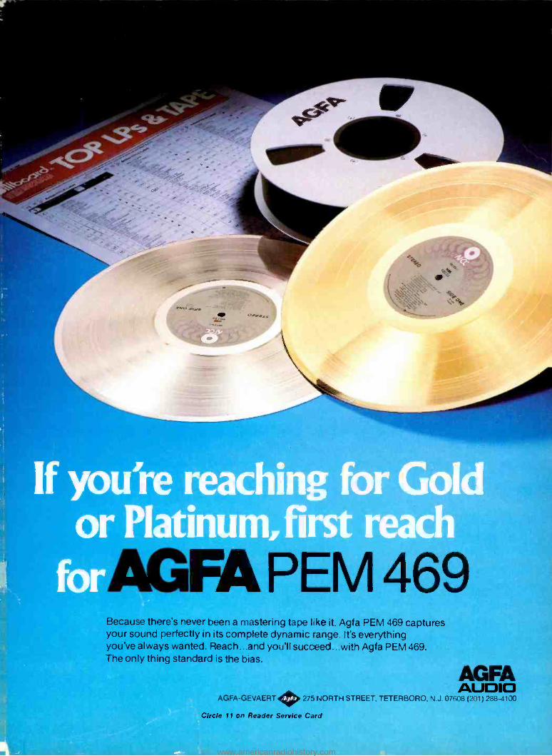
gir
If you're reaching for Gold or Platinum, rst
for Because there's never been a mastering tape like it. Agfa PEM 469 captures your sound perfectly in its complete dynamic range. It's everything you've always wanted. Reach...and you'll succeed...with Agfa PEM 469. The only thing standard is the bias.
AGFA AUDIO
AGFA -GEVAERT 275 NORTH STREET, TETERBORO, N.J. 07608 (201) 288 -4100
Circle 11 on Reader Service Card
www.americanradiohistory.com

Shure's new FP31 Mixer takes aì
a big weight off your shoulders. Introducing the most innovative field produc- tion mixer of its kind. Shure's FP31. You won't find another mixer this small with these fea- tures, dependability and ease of operation.
The FP31 measures only 65/16" x 55/16" x 17/8 ", and weighs just 2.2 pounds! Incredibly, it offers the same important features as much larger mixers. Plus, a few of its own.
Every channel has a mic/line level and a low -cut filter switch. And to prevent over- load distortion, there's a built - in limiter with adjustable threshold.
The FP31 can be powered by two internal 9 -volt batteries, or from an external 12 -volt source. A green LED flashes to remind you that the mixer is on. Phan- tom and A -B power are also provided to operate lavalier and 'shotgun microphones.
A slate tone can be laid
down on the tape for locating specific takes, and there's also a built -in mic for voice slating.
The mixer also has two separate mic/line outputs for 2- camera shoots and a tape output to feed a cassette. For monitoring, there are two stereo headphone jacks -one 1/4 -inch and one for miniplugs. The FP31's rugged nylon carrying case allows you easy access to every mixer func- tion and lets you piggyback the mixer on your
VCR or other equipment. For ENG, EFP and film use,
Shure's FP31 has everything you need to make your mix a perfect success. Coming from a mixer this small, that's quite an accomplishment.
For more information on Shure's FP31 Mixer, call or write Shure Brothers Inc., 222 Hartrey Ave., Evanston, IL 60204, (312) 866 -2553. SHU
THE SOUND OF THE PROFESSIONALS ...WORLDWIDE Circle 12 on Reader Service Card
www.americanradiohistory.com


![GOD’S SO BIG God’s so big [God’s so big] I’m so small [ I’m so small] Why does he love me, love me at all?](https://img.pdfslide.us/doc/110x75/551c3ace550346ea388b4935/gods-so-big-gods-so-big-gods-so-big-im-so-small-im-so-small-why-does-he-love-me-love-me-at-all.jpg)