Embed Size (px)
Citation preview
COMPUTERS IN EDUCATION JOURNAL 41
A LOW-COST ROBOT POSITIONING SYSTEM FOR A FIRST-YEAR ENGINEERING CORNERSTONE DESIGN PROJECT
David J. Frank, Kevin J. Witt, Chris Hartle,
Jacob J. Enders, Veronica Beiring, Richard J. Freuler Fundamentals of Engineering for Honors Program
The Ohio State University
Abstract Researchers in autonomous robotic design
have leveraged a variety of technologies to simulate the Global Positioning System (GPS) on a smaller laboratory or commercial scale. In the interest of cost and accuracy, a system was developed for The Ohio State University Fundamentals of Engineering for Honors (FEH) Program's "Cornerstone" Design Project. The system utilizes high definition commercial web cameras to accurately simulate a GPS for the autonomous robots created by students.
For the past 21 years The Ohio State
University has provided a "Cornerstone" Design Project for first-year honors engineering students. In this course, teams of students compete in a robot design competition, designing a fully-autonomous robot around a given microcontroller and within specified size and budget. The robots are tasked with completing several objectives on an 18 square foot course within a two-minute time period.
High definition Logitech C920 webcams were
chosen for the project based on their commercial availability and operating resolution of 1920 by 1080 pixels at a rate of 30 frames per second. Additionally, the cameras had a wide viewing angle which allowed them to be mounted six feet above each course. This provided sufficient coverage of each course and gave positional information to within a quarter of an inch and to within one degree. The system detected micro Quick Response (QR) codes, which were printed on three inch squares and mounted on each student's robot. The micro QR code data contained the name designation of each team.
The cameras were controlled by a National Instruments (NI) LabVIEW application. Via user interface, three specific locations were selected on each course to calibrate the coordinate systems and to account for any rotation with respect to the camera. Based on the calibrated coordinate system, the detected location and orientation was transmitted over radio frequency to each robot. Information relating to the progress of each robot in completing course tasks was overlaid with this positional information onto a live video feed of each course. These feeds were displayed in sets of four in a global user interface for a large-scale, real-time, visual representation of each competition round for viewing by observers during final competition.
The use of simulated GPS in the
"Cornerstone" Design course gave the students the advantage of working with real world concepts. The system introduced students to designing programs that interact with external systems in real time. It also introduced students to navigation without physical interaction with obstacles. This added to the variety of tools available to students for navigation which facilitated discussion between students on best design strategies. It allowed students to not only design software that acted based on a variety of inputs, but to design software that seamlessly transitioned between them as well.
Background and Introduction For the last twenty-one years in each spring
term, The Ohio State University FEH Program has incorporated an autonomous robot design project in which college freshman honors engineering students design, build, and program autonomous vehicles to perform certain well-
42 COMPUTERS IN EDUCATION JOURNAL
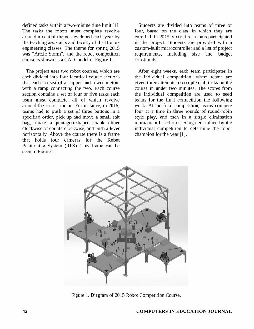
defined tasks within a two-minute time limit [1]. The tasks the robots must complete revolve around a central theme developed each year by the teaching assistants and faculty of the Honors engineering classes. The theme for spring 2015 was “Arctic Storm”, and the robot competition course is shown as a CAD model in Figure 1.
The project uses two robot courses, which are
each divided into four identical course sections that each consist of an upper and lower region, with a ramp connecting the two. Each course section contains a set of four or five tasks each team must complete, all of which revolve around the course theme. For instance, in 2015, teams had to push a set of three buttons in a specified order, pick up and move a small salt bag, rotate a pentagon-shaped crank either clockwise or counterclockwise, and push a lever horizontally. Above the course there is a frame that holds four cameras for the Robot Positioning System (RPS). This frame can be seen in Figure 1.
Students are divided into teams of three or four, based on the class in which they are enrolled. In 2015, sixty-three teams participated in the project. Students are provided with a custom-built microcontroller and a list of project requirements, including size and budget constraints.
After eight weeks, each team participates in
the individual competition, where teams are given three attempts to complete all tasks on the course in under two minutes. The scores from the individual competition are used to seed teams for the final competition the following week. At the final competition, teams compete four at a time in three rounds of round-robin style play, and then in a single elimination tournament based on seeding determined by the individual competition to determine the robot champion for the year [1].
Figure 1. Diagram of 2015 Robot Competition Course.
COMPUTERS IN EDUCATION JOURNAL 43
The students are encouraged to be creative so that each group produces a unique robot. In order to allow for a wide range of flexibility in design, the courses are built to enable different approaches. Some students may choose to navigate the course using line following, utilizing the lines placed on the floor of the course. Others may choose to track position using encoders to measure distance traveled and/or aligning with walls using bump switches. The Robot Positioning System provides students with an additional navigation option. With a basis similar to Global Positioning System technology that many students are familiar with, the RPS allows students to work with simulated real world tools to aid in their design. A large advantage is the ability to pinpoint robot location within the physical boundaries of the course. A bump switch may relay information as to which wall or walls a robot is aligned with but after moving away from the wall, the bump switches cannot provide positional information.
The first iteration of a robot positioning
system used the infrared (IR) sensors found in Nintendo Wii Remotes to track a pair of IR LEDs that were mounted on the students’ robots. This system then used an RF transmitter to send data to a robot controller so the students could use the data to further manage the navigation of their robots [2]. Previous research on different robotic tracking systems also exists. There have been similar systems that have utilized QR code-like tracking symbols [3]. Additionally, systems have been developed that utilize ultrasonic pulses or Microsoft Xbox Kinect cameras [4,5].
Motivation for Development
There are several reasons why it was decided
to overhaul the original system that utilized IR sensors. First, the limitations of the Wii remote IR sensor were continuously causing setbacks. The proper IR sensors themselves were exclusive to the Nintendo Wii Remote. It was near impossible to obtain the sensor as its own component for less than the cost of a Wii remote. Thus, the sensor then had to be
unsoldered from the main circuit board in the Wii Remote which at times led to damage to the delicate pins coming off of the sensors. In order to mitigate this issue, an imaging device with an off-the-shelf replacement was desirable. Also, all of the Wii Remotes communicated over the Inter-Integrated Circuit (I2C) protocol. Since the sensors were sufficiently far from the main processor and since I2C does not inherently make use of differential signaling, corrupted data was experienced due to the length of the wire between the sensor and the processor. In the new system, it was determined that a protocol that makes use of differential signaling would be ideal. Additionally, each of the sensors had the same non-configurable I2C address, meaning that they could not be daisy chained [6]. Because of this, additional custom hardware was needed in order to correctly communicate with the sensors (e.g. an I2C multiplexer). Lastly, using active equipment on the students’ robots (i.e. the two IR LEDs) was difficult to maintain and often times were inadvertently destroyed by students shorting out pins on the LED bar that was given to them. Additionally, it was difficult to determine if they were working or not because IR light is undetectable by the human eye.
Moreover, the system was fairly complex and
difficult to maintain by the teaching assistant staff. In the first year program, the teaching assistants normally stayed with the program only while obtaining their degrees. Because of the turnover of personnel within the teaching assistant staff, it is necessary to make a system that is easy to learn in order to ensure that it is maintainable.
System Architecture
The system architecture was driven by the
primary requirement to track each robot consistently, repeatedly, and quickly. Furthermore, the system needed to communicate wirelessly to active robots on the course, and with a centralized course computer that contained other essential information. With these requirements, the initial design and
44 COMPUTERS IN EDUCATION JOURNAL
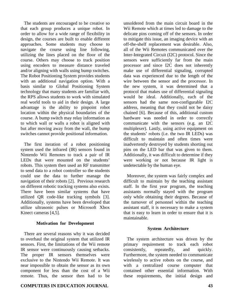
prototyping stages focused on identifying processing hardware, cameras, wireless transmitters, and image templates that best met these objectives. Evaluation of these methods identified USB 3.0 web cameras, micro QR codes, XBee wireless transmitters, and LabVIEW’s machine vision tools as the optimal components for the system. This solution met all of the system requirements, while providing additional benefits including visual monitoring and debugging of the system in real time. The final system architecture is detailed below in Figure 2.
Initial development analyzed the effectiveness
of multiple templates and evaluated them based on their speed of detectability, detectability when in motion, detectability at various angles, and required template size to be detectable at a range of 10 feet. Using LabVIEW’s machine vision tools, it was determined that the QR code detection libraries provided a significant advantage in recognition speeds over other pattern templates. However, the size of traditional QR codes made them too obtrusive and affected student design freedom. Custom
designed patterns proved difficult to detect with minor tilt, and did not meet the desired minimum update rate of 10 Hz — chosen to allow for quick real-time position adjustments. Micro QR codes provided the solution to both of these issues.
The smaller 13x13 Micro QR codes were
detectable at 10 feet with a 3x3 inch template. Furthermore, using QR codes added the benefit of encoding each robot’s team designation in the QR codes. Through leveraging the consistency of the LabVIEW QR code detection tool in labelling coordinates, it was also possible to calculate a precise 0 to 360 degree heading, contrary to the limited 180 degree heading of the former system that utilized IR LEDs. Finally, by using the location of the QR code detected in the previous frame, the QR code detection algorithm was modified to search only a portion of the image surrounding the previous location. Using this region of interest reduced the average detection time by over 50 percent. These benefits made using micro QR codes optimal for the RPS system.
Figure 2. Block diagram of the RPS system architecture.
COMPUTERS IN EDUCATION JOURNAL 45
A full course is comprised of four individual course sections, and a total of four cameras are needed to cover a full course. Each course section is monitored by a Logitech C920 web camera, which allows recording at 1920 by 1080 pixels at 30 frames per second. The camera’s view is square to and centered with respect to the plane of the course section with minimal to no skew or tilt. It is raised to approximately 6 feet over the top of the lower course section to allow the entirety of the course section to be in full view while also leaving addition space in the image feed to be later covered by UI elements
One computer is used to run a full course. It is
configured with a 4 port USB 3.0 PCI express card to allow all cameras to communicate at their fastest possible speed. It also contains a quad core CPU and dedicated graphics card to support image processing and an advanced graphical user interface (GUI).
The LabVIEW code running the system is
integrated with an NI Vision module that is fed an image with a QR code and outputs location and QR code data from that image. Location information from this model is converted to inches and adjusted to the coordinate system of the course. This information, in addition to objective information relating to the competition scenario, is then wirelessly transmitted to robots using Digi International’s XBee radio transmitters. The location information is also used in the graphical overlays that are put over the image of each course. Overlays consist of a mix of bitmap images and LabVIEW-drawn shapes. LabVIEW- drawn shapes are used when possible, and are primarily used to represent buttons or lights. Bitmap images are used for visual information more complex than circles or squares, and are usually used to represent structures on the course.
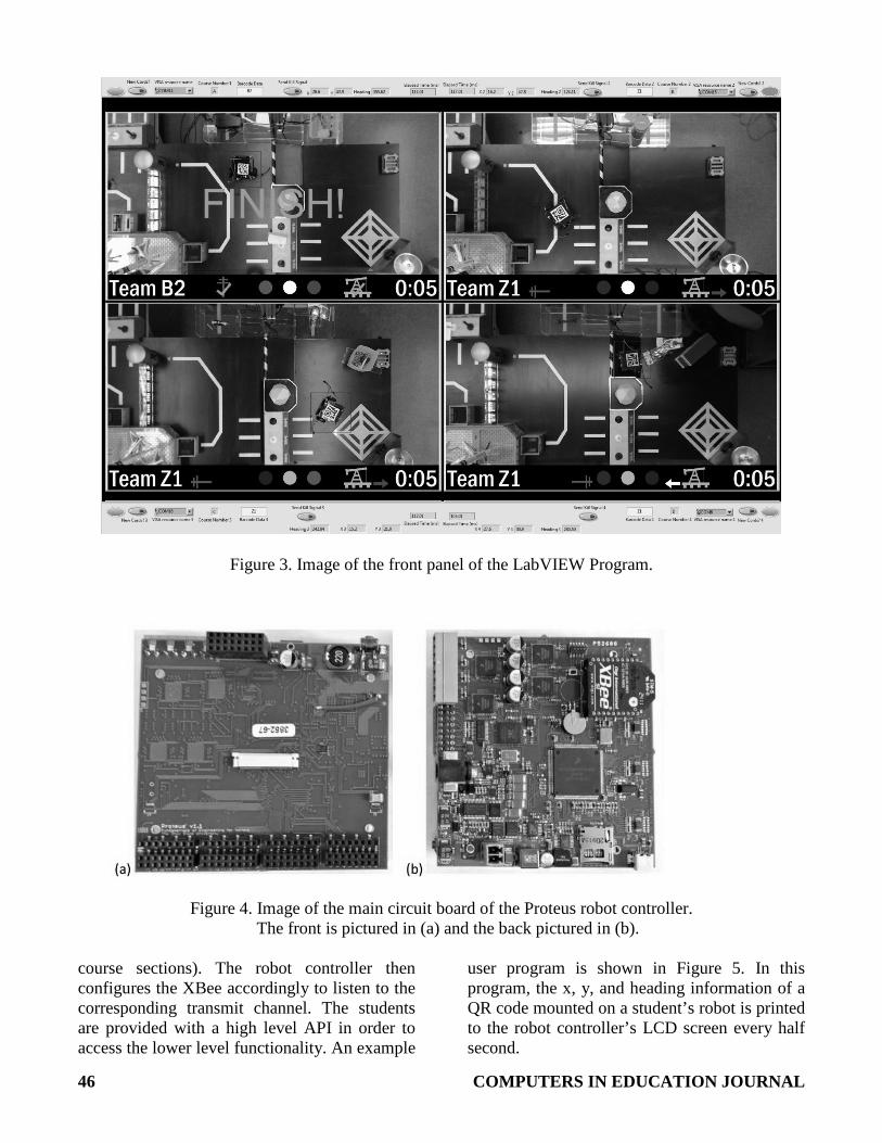
The front panel of the LabVIEW program
functions as a GUI for the RPS control program. The GUI, which can be seen in Figure 3, allows the positioning system to be individually turned on and off for each course section. It also allows
each course section to be re-calibrated upon activation or to start up with previously generated calibration data. Additionally, the GUI provides access to advanced controls and information that are outside of the default GUI view, but can be accessed by scrolling.
The primary area of the GUI is dedicated to
the four live camera image feeds that correspond to the four course sections. These color video feeds in the GUI are updated at the maximum possible frame rate of the system, which is no less than ten frames per second and can approach 30 frames per second. Objective information is overlaid in a strip at the bottom of each feed. While objective information is dependent on the scenario theme for a particular year, such information usually consists of items such as team designation corresponding to the robot currently on the course, button or lever activation, time left in a match, and interaction with moveable course objects. Additionally, a small tracking box is drawn over the position of the QR code in the image feed. This objective information combined with the live camera image feed provides a clear and comprehensive view for observers not familiar with the nature of the robot competition.
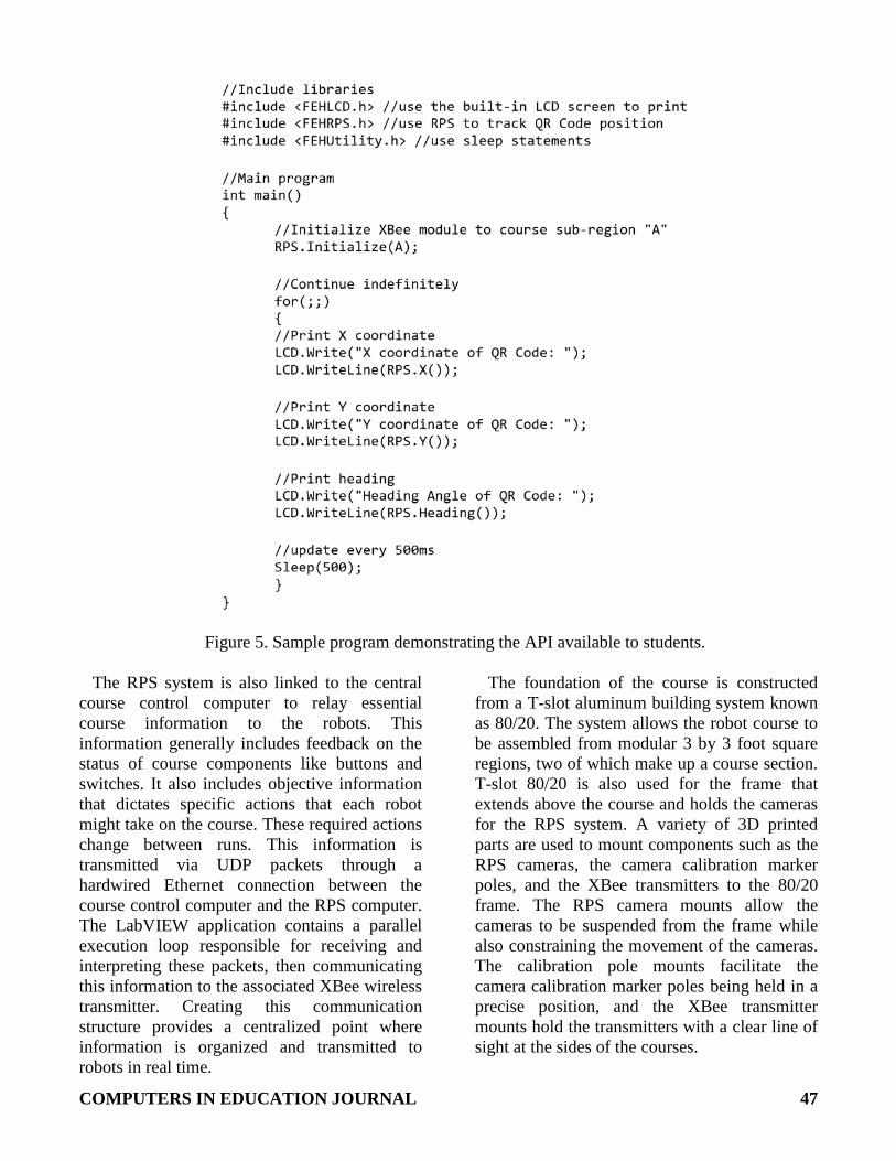
Ultimately, the goal of the RPS is to provide a
robot controller with the position of the QR Code on a student’s robot. The current Proteus robot controller [7] has an integrated XBee receiver to allow it to communicate with the XBee transmitters on the course. The Proteus’s main circuit board showing the XBee module can be seen in Figure 4.
In order to have individual communication,
the XBee receivers in each controller and the XBee transmitters on each course section must be paired to the same channel. Since there are two courses each with 4 course sections, there are 8 different static transmit addresses which broadcast robot positional data and course objective information. When a robot is ready to run on a course section, the user must input what course section the robot is running on (the sections are lettered A-H which represent the 8
46 COMPUTERS IN EDUCATION JOURNAL
Figure 3. Image of the front panel of the LabVIEW Program.
Figure 4. Image of the main circuit board of the Proteus robot controller. The front is pictured in (a) and the back pictured in (b).
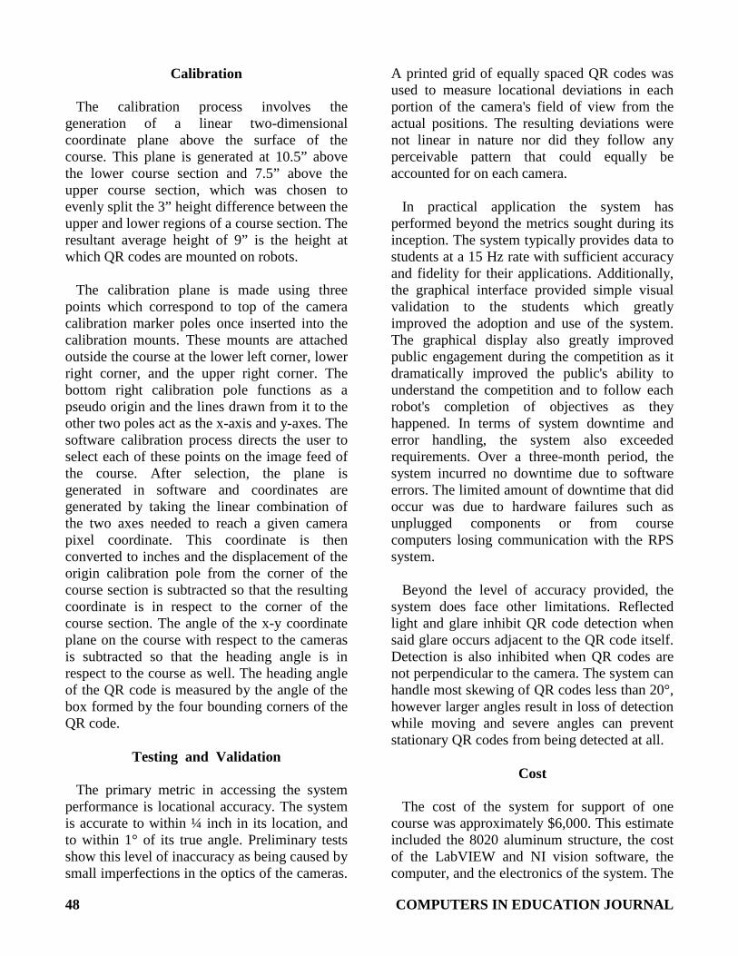
course sections). The robot controller then configures the XBee accordingly to listen to the corresponding transmit channel. The students are provided with a high level API in order to access the lower level functionality. An example
user program is shown in Figure 5. In this program, the x, y, and heading information of a QR code mounted on a student’s robot is printed to the robot controller’s LCD screen every half second.
COMPUTERS IN EDUCATION JOURNAL 47
Figure 5. Sample program demonstrating the API available to students.
The RPS system is also linked to the central course control computer to relay essential course information to the robots. This information generally includes feedback on the status of course components like buttons and switches. It also includes objective information that dictates specific actions that each robot might take on the course. These required actions change between runs. This information is transmitted via UDP packets through a hardwired Ethernet connection between the course control computer and the RPS computer. The LabVIEW application contains a parallel execution loop responsible for receiving and interpreting these packets, then communicating this information to the associated XBee wireless transmitter. Creating this communication structure provides a centralized point where information is organized and transmitted to robots in real time.
The foundation of the course is constructed from a T-slot aluminum building system known as 80/20. The system allows the robot course to be assembled from modular 3 by 3 foot square regions, two of which make up a course section. T-slot 80/20 is also used for the frame that extends above the course and holds the cameras for the RPS system. A variety of 3D printed parts are used to mount components such as the RPS cameras, the camera calibration marker poles, and the XBee transmitters to the 80/20 frame. The RPS camera mounts allow the cameras to be suspended from the frame while also constraining the movement of the cameras. The calibration pole mounts facilitate the camera calibration marker poles being held in a precise position, and the XBee transmitter mounts hold the transmitters with a clear line of sight at the sides of the courses.
48 COMPUTERS IN EDUCATION JOURNAL
Calibration The calibration process involves the
generation of a linear two-dimensional coordinate plane above the surface of the course. This plane is generated at 10.5” above the lower course section and 7.5” above the upper course section, which was chosen to evenly split the 3” height difference between the upper and lower regions of a course section. The resultant average height of 9” is the height at which QR codes are mounted on robots.
The calibration plane is made using three
points which correspond to top of the camera calibration marker poles once inserted into the calibration mounts. These mounts are attached outside the course at the lower left corner, lower right corner, and the upper right corner. The bottom right calibration pole functions as a pseudo origin and the lines drawn from it to the other two poles act as the x-axis and y-axes. The software calibration process directs the user to select each of these points on the image feed of the course. After selection, the plane is generated in software and coordinates are generated by taking the linear combination of the two axes needed to reach a given camera pixel coordinate. This coordinate is then converted to inches and the displacement of the origin calibration pole from the corner of the course section is subtracted so that the resulting coordinate is in respect to the corner of the course section. The angle of the x-y coordinate plane on the course with respect to the cameras is subtracted so that the heading angle is in respect to the course as well. The heading angle of the QR code is measured by the angle of the box formed by the four bounding corners of the QR code.
Testing and Validation
The primary metric in accessing the system
performance is locational accuracy. The system is accurate to within ¼ inch in its location, and to within 1° of its true angle. Preliminary tests show this level of inaccuracy as being caused by small imperfections in the optics of the cameras.
A printed grid of equally spaced QR codes was used to measure locational deviations in each portion of the camera's field of view from the actual positions. The resulting deviations were not linear in nature nor did they follow any perceivable pattern that could equally be accounted for on each camera.
In practical application the system has
performed beyond the metrics sought during its inception. The system typically provides data to students at a 15 Hz rate with sufficient accuracy and fidelity for their applications. Additionally, the graphical interface provided simple visual validation to the students which greatly improved the adoption and use of the system. The graphical display also greatly improved public engagement during the competition as it dramatically improved the public's ability to understand the competition and to follow each robot's completion of objectives as they happened. In terms of system downtime and error handling, the system also exceeded requirements. Over a three-month period, the system incurred no downtime due to software errors. The limited amount of downtime that did occur was due to hardware failures such as unplugged components or from course computers losing communication with the RPS system.
Beyond the level of accuracy provided, the
system does face other limitations. Reflected light and glare inhibit QR code detection when said glare occurs adjacent to the QR code itself. Detection is also inhibited when QR codes are not perpendicular to the camera. The system can handle most skewing of QR codes less than 20°, however larger angles result in loss of detection while moving and severe angles can prevent stationary QR codes from being detected at all.
Cost
The cost of the system for support of one
course was approximately $6,000. This estimate included the 8020 aluminum structure, the cost of the LabVIEW and NI vision software, the computer, and the electronics of the system. The
COMPUTERS IN EDUCATION JOURNAL 49
effective cost of the system for the First-Year Engineering Honors Program was lower as the program was already in possession of the licensed software and most of the T-slot 80/20 aluminum structures. As a result, the effective cost was approximately $2,500 per course.
Concluding Remarks
The low-cost positioning system known as
RPS enriched the overall student experience in the first-year cornerstone design project. The system functioned by tracking micro QR codes by using high definition cameras. A computer vision interface provided by NI LabVIEW allows real-time positioning information to be interpreted by the position of the QR code in the camera's field of view. The position data is then wirelessly transmitted to a robot controller, and high level functions are provided to the students in order to imitate a real-world GPS system. This architecture proved to be much faster, more accurate, and more reliable than previous systems that have been used. By providing students with this tool, the learning experience was significantly enhanced by allowing students to interact with a system much like what they would encounter in a professional environment.
References 1. Freuler, R.J., M.J. Hoffmann, T.P.
Pavlic, J.M. Beams, J.P. Radigan, P.K. Dutta, J.T. Demel, and E.D. Justen: "Experiences with a Comprehensive Freshman Hands-On Course – Designing, Building, and Testing Small Autonomous Robots", Proceedings of the 2003 American Society for Engineering Education Annual Conference, Nashville, Tennessee, June 2003. https://peer.asee.org/11882.
2. Vernier, M.A., C.E. Morin, P.M.
Wensing, R.M. Hartlage, B.E. Carruthers, and R.J. Freuler: "Use of a Low- Cost Camera-Based Positioning System in a First-Year Engineering Cornerstone Design Project",
Proceedings of the 2009 American Society for Engineering Education Annual Conference, Austin, Texas, June 2009. https://peer.asee.org/5632. Also published in the Computers in Education Division of ASEE Computers in Education Journal, Vol. XX, No. 2, pp. 6-14, April-June 2010.
3. Biddlestone, S., A. Kurt, M. Vernier, K.
Redmill, and Ü. Özgüner, "An indoor Intelligent Transportation Testbed for Urban Traffic Scenarios", Proceedings of the International IEEE Conference on Intelligent Transportation Systems, St. Louis, Missouri, 2009.
4. Smith, A., H. Chang, and E. Blanchard:
"An outdoor high-accuracy local positioning system for an autonomous robotic golf greens mower," Robotics and Automation (ICRA), 2012 IEEE International Conference, May 2012, pp. 2633-2639.
5. Benavidez, P., and M. Jamshidi: "Mobile
robot navigation and target tracking system", Proceedings of the 6th International Conference on System of Systems Engineering: SoSE in Cloud Computing, Smart Grid, and Cyber Security, SoSE 2011, Albuquerque, NM, USA, 2011; pp. 299-304.
6. NXP Semiconductors, "I2C-bus
Specification and user manual", Internet: http://www.nxp.com/documents/user_manual/UM10204.pdf, Rev 6, April 2014, accessed 27 Jan 2016.
7. Vernier, M.A., P.M. Wensing, C.E.
Morin, A.H. Phillips, B.A. Rice, K.R. Wegman, C.P. Hartle, P.A. Clingan, K.M. Kecskemety, and R.J. Freuler: "Design of a Full-Featured Robot Controller for Use in a First-Year Robotics Design Project", Proceedings of the 2014 American Society for Engineering Education Annual
50 COMPUTERS IN EDUCATION JOURNAL
Conference, Indianapolis, Indiana, June 2014. https://peer.asee.org/20260. Also published in the Computers in Education Division of ASEE Computers in Education Journal, Vol. XXV, No. 1, pp. 42-65, January-March, 2015.
Biographical Information
David J. Frank is a 3rd year Computer
Engineering honors student at The Ohio State University and an Undergraduate Teaching Assistant for the Fundamentals of Engineering for Honors program. He will graduate with his B.S.E.C.E in May 2017, and is expected to graduate with his M.S.E.C.E in May 2018.
Kevin Witt received his BS in Electrical and
Computer Engineering from The Ohio State University in 2014. He is currently pursuing his MS in the same field and is set to graduate in 2016. His specialization is in computer and circuits, and he is the lead electronics developer for the First Year Honors Engineering Program in the College of Engineering at OSU. He has been with the program since 2012.
Chris Hartle graduated from The Ohio State
University with a Bachelor’s degree in 2014 and a Master’s degree in 2015, both in Electrical & Computer Engineering. Chris worked as a Graduate Teaching Assistant for the Fundamentals of Engineering for Honors program at Ohio State. His work includes embedded systems development.
Jacob J. Enders is a Biomedical Engineering
honors student at The Ohio State University and an Undergraduate Teaching Assistant for the Fundamentals of Engineering for Honors program. He is a member of the Eminence Fellows scholarship program and is a research assistant studying cancer cell migration and metastasis using DNA force sensors. He will graduate with his B.S.B.M.E. in May 2018.
Veronica M. Beiring is an Electrical Engineering student at The Ohio State University and an Undergraduate Teaching Assistant for the OSU Fundamentals of Engineering for Honors (FEH) Program.
Richard J. Freuler is the Director for the
Fundamentals of Engineering for Honors (FEH) Program in the OSU Department of Engineering Education. He teaches the two-semester FEH engineering course sequence and is active in engineering education research. He is also a Professor of Practice in the Me- chanical and Aerospace Engineering Department and conducts scale model investigations of gas turbine installations for jet engine test cells and for marine and industrial applications of gas turbines at the Aerospace Research Center at Ohio State. Dr. Freuler earned his Bachelor of Aeronautical and Astronautical Engineering (1974), his B.S. in Computer and Information Science (1974), his M.S. in Aeronautical Engineering (1974), and his Ph.D. in Aeronautical and Astronautical Engineering (1991) all from The Ohio State University.