Embed Size (px)
Citation preview
AC 2011-1759: A LOW COST PROJECT COURSE TO ENHANCE LEARN-ING IN A STATICS AND STRENGTH OF MATERIALS COURSE
Charles G. Drake, Ferris State University
Professor, Mechanical Engineering Technology Ferris State University Big Rapids, Michigan
MS Mechanical Engineering Michigan Technological University BS mathematics Lake Superior StateUniversity
12 years in Product Development, R & D, Reynolds Metals Company (now ALCOA) Richmond, Virginia
c©American Society for Engineering Education, 2011
Page 22.60.1
A Low Cost Lab Project Course to Enhance Learning
in a Statics and Strengths of Materials Course
Abstract
A lab-oriented course has been created to supplement lecture instruction in statics and strengths
of materials. The primary goal in initiating the course was to give students more problem
solving experience with a secondary goal of intuition-building hands-on experiences. Over 25
activities have been developed with a limited budget.
Background
Second year students in Mechanical Engineering Technology take a four-credit lecture course in
statics and strengths of materials during their fall semester. Prerequisites for the lecture course
include pre-calculus and college physics. The lecture course includes two-dimensional statics,
stress and deformation for common loadings, and combined loadings with Mohr‟s circle.
Fastener design and column buckling are introduced. Such courses are often challenging due
both to the nature of the subjects themselves and to students being at the beginning of the
development of their aptitudes in mathematics-based problem solving.
Starting as an experimental course in Fall 1999, faculty have created the one-credit lab based
course to provide more problem-solving experience in these very important subjects. Covering
the course material with 4 hours of lecture has always been challenging. The lab was created to
supplement instruction for MET students.
This document covers experience from the first years of the course which were done generally
with low cost/no cost equipment. A sequential paper is planned; the future paper will discuss
equipment enhancements and the continued development of the course.
The text used when this lab course was created was H. W. Morrow‟s Statics and Strengths of
Materials.1
Work by others teaching mechanics includes discussion and student feedback on the integration
of real life examples into a solid mechanics course at Michigan State University. Here students
had a very favorable impression of their learning experience when examples such as skateboards,
basketball hoops, and iPods™ were used to develop key concepts in solid mechanics.2
Pedagogy
The course emphasizes activity learning with generally hands-on equipment experiences
followed by applied computations. The author uses the whiteboard for visual and auditory
explanations. Text is kept to a minimum on author‟s handouts in deference to those who learn
poorly through reading.
Page 22.60.2
Overview of the Lab-Based Course
As stated, over twenty-five activities have been developed. Nearly all activities include hands-
on experiments using low cost equipment and materials. Each activity included a worksheet for
data, observations, free-body diagrams, and mathematical problem-solving.
The statics portion of the course included activities relating to units, scaling, vectors, concurrent
forces, pulley systems, beam reactions and stability, dry friction, belt friction, trusses, and the
human arm. Low-cost readily-available equipment included engineers‟ scales, protractors,
pulleys, spaghetti, and torque wrenches. Purchased equipment included five high-quality
commercial force gauges with ranges of 100 lb/500 N, 20 lb/100 N, and 176 oz/50 N.
The strength of materials portion of the course involved tensile strength, fastener shear, shear and
tensile modulii, and torsional deformation. Low cost materials used solid aluminum rivets and
foam sponges. A commercial torsional deformation device was purchased; this was
supplemented with two student-build torsional deformation devices. The force gauges
mentioned previously along with a donated universal testing machine were used.
Near the end of the semester instructor led truss and frame design projects were completed.
These thoroughly analyzed projects included stability, frame member selection and analysis,
fastener analysis, and buckling considerations. A load rating for each structure was established.
Finally, a fun hands-on competition and a computer lab session with multiple exercises with
MDSolids™ were used to complete the course.
Nature of Lab Sessions
Lab sessions began with a white board review of principles involved and procedures for the
session‟s experiments. Instructor provided “fill-in” worksheet handouts were used in most
experiments. Students were assigned to small groups for the semester. The instructor
established a rotation for groups to proceed through experiments when equipment was limited.
The two-hour sessions were busy, but most work was completed during the lab times. Write-
ups, on the lab worksheets, were generally collected at the end of the lab period.
A Sampling of Activities
A complete list of activities appears in Table 2. Several of the activities are discussed here.
More information is available on request by contacting the author.
“What‟s a Newton?”: With credit to Associate Professor XXXX, a simple first day
activity was developed to give students an intuitive sense of the force of a newton and do
unit conversions. Initially students determined how many Hersey‟s Kisses™ were in a
newton – and some remembered the figure years later. Other common items could be
used as well. The activity resulted in the equivalent of 2 homework problems.
Page 22.60.3
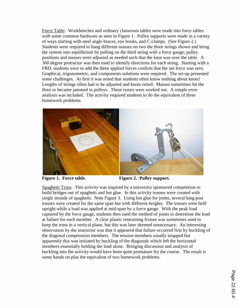
Force Table: Workbenches and ordinary classroom tables were made into force tables
with some common hardware as seen in Figure 1. Pulley supports were made in a variety
of ways starting with steel angle braces, eye hooks, and C-clamps. (See Figure 2.)
Students were required to hang different masses on two the three strings shown and bring
the system into equilibrium by pulling on the third string with a force gauge; pulley
positions and masses were adjusted as needed such that the knot was over the table. A
360 degree protractor was then used to identify directions for each string. Starting with a
FBD, students were to add the three applied forces confirm that the net force was zero.
Graphical, trigonometric, and components solutions were required. The set-up presented
some challenges. At first it was noted that students often know nothing about knots!
Lengths of strings often had to be adjusted and knots retied. Masses sometimes hit the
floor or became jammed in pulleys. These issues were worked out. A simple error
analysis was included. The activity required students to do the equivalent of three
homework problems.
Figure 1. Force table. Figure 2. Pulley support.
Spaghetti Truss: This activity was inspired by a university sponsored competition to
build bridges out of spaghetti and hot glue. In this activity trusses were created with
single strands of spaghetti. Note Figure 3. Using hot glue for joints, several king post
trusses were created for the same span but with different heights. The trusses were held
upright while a load was applied at mid-span by a force gauge. With the peak load
captured by the force gauge, students then used the method of joints to determine the load
at failure for each member. A clear plastic restraining fixture was sometimes used to
keep the truss in a vertical plane, but this was later deemed unnecessary. An interesting
observation by the instructor was that it appeared that failure occurred first by buckling of
the diagonal compression members. The tension members usually snapped but
apparently this was initiated by buckling of the diagonals which left the horizontal
members essentially holding the load alone. Bringing discussion and analysis of
buckling into the activity would have been quite premature for the course. The result is
some hands on plus the equivalent of two homework problems.
Page 22.60.4
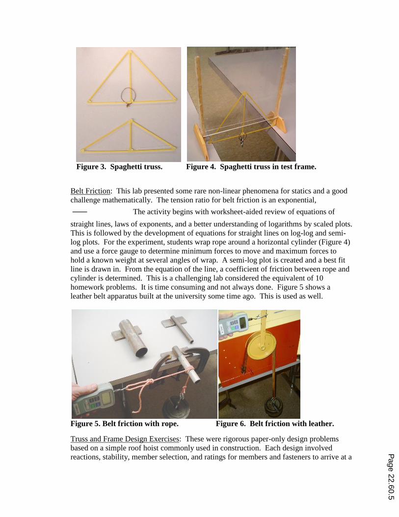
Figure 3. Spaghetti truss. Figure 4. Spaghetti truss in test frame.
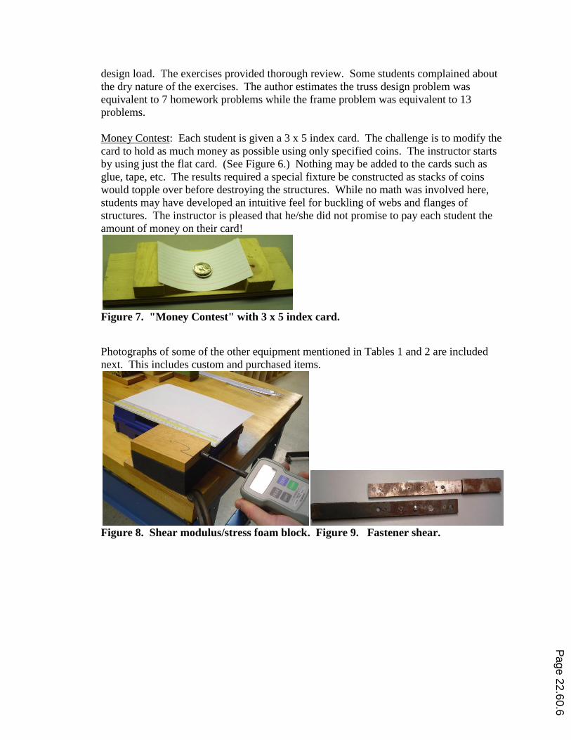
Belt Friction: This lab presented some rare non-linear phenomena for statics and a good
challenge mathematically. The tension ratio for belt friction is an exponential,
The activity begins with worksheet-aided review of equations of
straight lines, laws of exponents, and a better understanding of logarithms by scaled plots.
This is followed by the development of equations for straight lines on log-log and semi-
log plots. For the experiment, students wrap rope around a horizontal cylinder (Figure 4)
and use a force gauge to determine minimum forces to move and maximum forces to
hold a known weight at several angles of wrap. A semi-log plot is created and a best fit
line is drawn in. From the equation of the line, a coefficient of friction between rope and
cylinder is determined. This is a challenging lab considered the equivalent of 10
homework problems. It is time consuming and not always done. Figure 5 shows a
leather belt apparatus built at the university some time ago. This is used as well.
Figure 5. Belt friction with rope. Figure 6. Belt friction with leather.
Truss and Frame Design Exercises: These were rigorous paper-only design problems
based on a simple roof hoist commonly used in construction. Each design involved
reactions, stability, member selection, and ratings for members and fasteners to arrive at a
Page 22.60.5
design load. The exercises provided thorough review. Some students complained about
the dry nature of the exercises. The author estimates the truss design problem was
equivalent to 7 homework problems while the frame problem was equivalent to 13
problems.
Money Contest: Each student is given a 3 x 5 index card. The challenge is to modify the
card to hold as much money as possible using only specified coins. The instructor starts
by using just the flat card. (See Figure 6.) Nothing may be added to the cards such as
glue, tape, etc. The results required a special fixture be constructed as stacks of coins
would topple over before destroying the structures. While no math was involved here,
students may have developed an intuitive feel for buckling of webs and flanges of
structures. The instructor is pleased that he/she did not promise to pay each student the
amount of money on their card!
Figure 7. "Money Contest" with 3 x 5 index card.
Photographs of some of the other equipment mentioned in Tables 1 and 2 are included
next. This includes custom and purchased items.
Figure 8. Shear modulus/stress foam block. Figure 9. Fastener shear.
Page 22.60.6
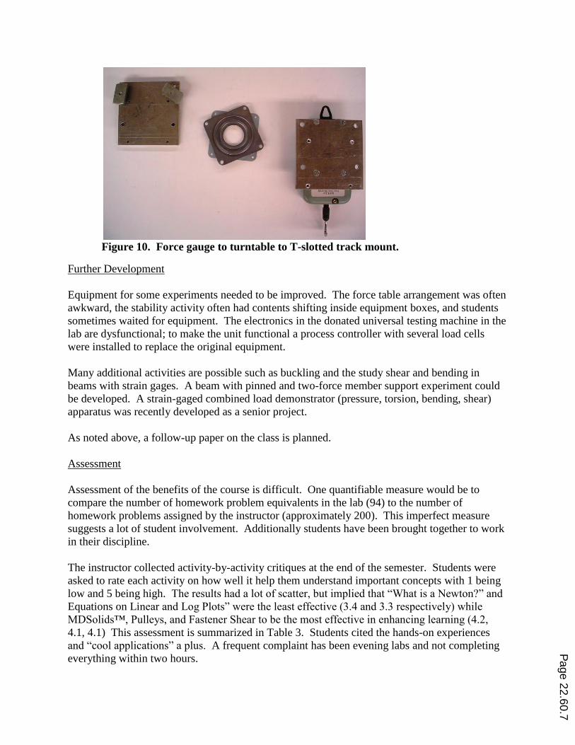
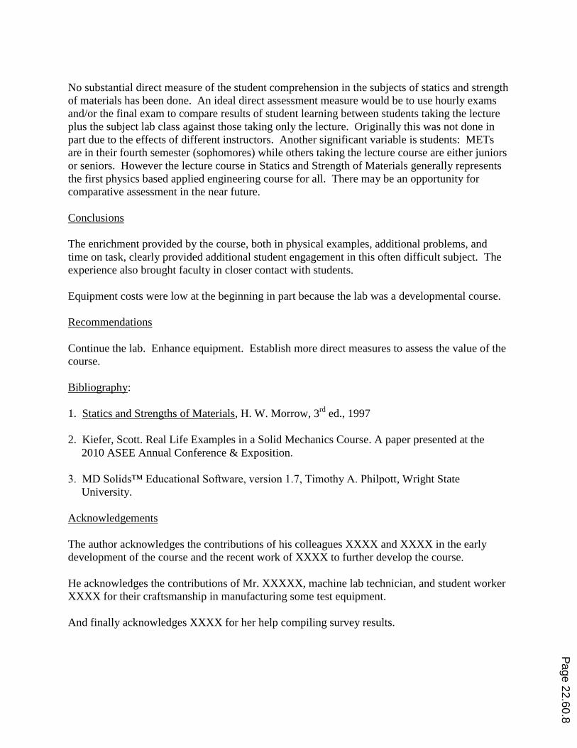
Figure 10. Force gauge to turntable to T-slotted track mount.
Further Development
Equipment for some experiments needed to be improved. The force table arrangement was often
awkward, the stability activity often had contents shifting inside equipment boxes, and students
sometimes waited for equipment. The electronics in the donated universal testing machine in the
lab are dysfunctional; to make the unit functional a process controller with several load cells
were installed to replace the original equipment.
Many additional activities are possible such as buckling and the study shear and bending in
beams with strain gages. A beam with pinned and two-force member support experiment could
be developed. A strain-gaged combined load demonstrator (pressure, torsion, bending, shear)
apparatus was recently developed as a senior project.
As noted above, a follow-up paper on the class is planned.
Assessment
Assessment of the benefits of the course is difficult. One quantifiable measure would be to
compare the number of homework problem equivalents in the lab (94) to the number of
homework problems assigned by the instructor (approximately 200). This imperfect measure
suggests a lot of student involvement. Additionally students have been brought together to work
in their discipline.
The instructor collected activity-by-activity critiques at the end of the semester. Students were
asked to rate each activity on how well it help them understand important concepts with 1 being
low and 5 being high. The results had a lot of scatter, but implied that “What is a Newton?” and
Equations on Linear and Log Plots” were the least effective (3.4 and 3.3 respectively) while
MDSolids™, Pulleys, and Fastener Shear to be the most effective in enhancing learning (4.2,
4.1, 4.1) This assessment is summarized in Table 3. Students cited the hands-on experiences
and “cool applications” a plus. A frequent complaint has been evening labs and not completing
everything within two hours.
Page 22.60.7
No substantial direct measure of the student comprehension in the subjects of statics and strength
of materials has been done. An ideal direct assessment measure would be to use hourly exams
and/or the final exam to compare results of student learning between students taking the lecture
plus the subject lab class against those taking only the lecture. Originally this was not done in
part due to the effects of different instructors. Another significant variable is students: METs
are in their fourth semester (sophomores) while others taking the lecture course are either juniors
or seniors. However the lecture course in Statics and Strength of Materials generally represents
the first physics based applied engineering course for all. There may be an opportunity for
comparative assessment in the near future.
Conclusions
The enrichment provided by the course, both in physical examples, additional problems, and
time on task, clearly provided additional student engagement in this often difficult subject. The
experience also brought faculty in closer contact with students.
Equipment costs were low at the beginning in part because the lab was a developmental course.
Recommendations
Continue the lab. Enhance equipment. Establish more direct measures to assess the value of the
course.
Bibliography:
1. Statics and Strengths of Materials, H. W. Morrow, 3rd
ed., 1997
2. Kiefer, Scott. Real Life Examples in a Solid Mechanics Course. A paper presented at the
2010 ASEE Annual Conference & Exposition.
3. MD Solids™ Educational Software, version 1.7, Timothy A. Philpott, Wright State
University.
Acknowledgements
The author acknowledges the contributions of his colleagues XXXX and XXXX in the early
development of the course and the recent work of XXXX to further develop the course.
He acknowledges the contributions of Mr. XXXXX, machine lab technician, and student worker
XXXX for their craftsmanship in manufacturing some test equipment.
And finally acknowledges XXXX for her help compiling survey results.
Page 22.60.8
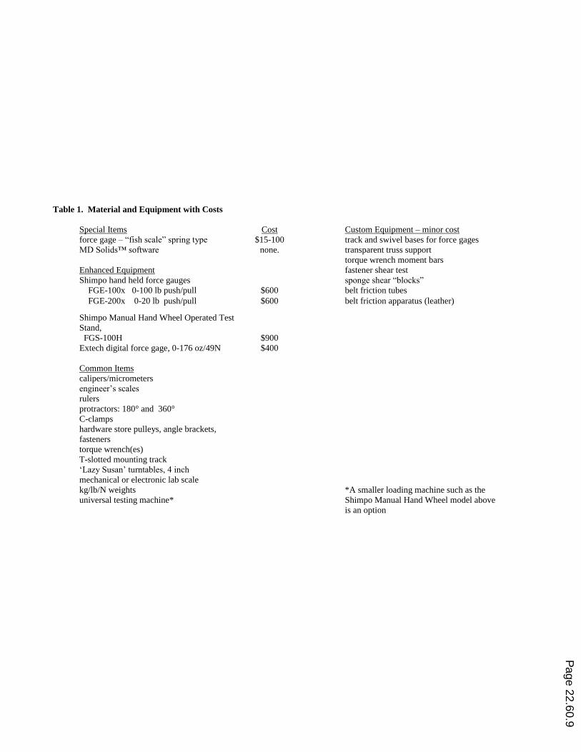
Table 1. Material and Equipment with Costs
Special Items Cost Custom Equipment – minor cost
force gage – “fish scale” spring type $15-100 track and swivel bases for force gages
MD Solids™ software none. transparent truss support
torque wrench moment bars
Enhanced Equipment fastener shear test
Shimpo hand held force gauges sponge shear “blocks”
FGE-100x 0-100 lb push/pull $600 belt friction tubes
FGE-200x 0-20 lb push/pull $600 belt friction apparatus (leather)
Shimpo Manual Hand Wheel Operated Test
Stand,
FGS-100H
$900
Extech digital force gage, 0-176 oz/49N
$400
Common Items
calipers/micrometers
engineer‟s scales
rulers
protractors: 180° and 360°
C-clamps
hardware store pulleys, angle brackets,
fasteners
torque wrench(es)
T-slotted mounting track
„Lazy Susan‟ turntables, 4 inch
mechanical or electronic lab scale
kg/lb/N weights
universal testing machine*
*A smaller loading machine such as the
Shimpo Manual Hand Wheel model above
is an option
Page 22.60.9
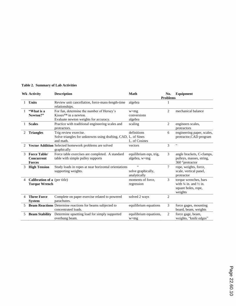
Table 2. Summary of Lab Activities
Wk Activity Description Math No.
Problems
Equipment
1 Units Review unit cancellation, force-mass-length-time
relationships.
algebra 1
1 “What is a
Newton?”
For fun, determine the number of Hersey‟s
Kisses™ in a newton.
Evaluate newton weights for accuracy.
w=mg
conversions
algebra
2 mechanical balance
1 Scales Practice with traditional engineering scales and
protractors.
scaling 2 engineers scales,
protractors
2 Triangles Trig review exercise.
Solve triangles for unknowns using drafting, CAD,
and math.
definitions
L. of Sines
L. of Cosines
6 engineering paper, scales,
protractor,CAD program
2 Vector Addition Selected homework problems are solved
graphically
vectors 3 “
3 Force Table/
Concurrent
Forces
Force table exercises are completed. A standard
table with simple pulley supports
equilibrium eqn, trig,
algebra, w=mg
3 angle brackets, C-clamps,
pulleys, masses, string,
360 °protractor
3 High Tension Study loads in ropes at near horizontal orientations
supporting weights.
“
solve graphically,
analytically
7 rope, weights, force,
scale, vertical panel,
protractor
4 Calibration of a
Torque Wrench
(per title) moments of force,
regression
3 torque wrenches, bars
with ¼ in. and ½ in.
square holes, rope,
weights
4 Three Force
System
Complete on paper exercise related to powered
parachutes.
solved 2 ways 2
5 Beam Reactions Determine reactions for beams subjected to
concentrated loads.
equilibrium equations 3 force gages, mounting
board, beam, weights
5 Beam Stability Determine upsetting load for simply supported
overhung beam.
equilibrium equations,
w=mg
2 force gage, beam,
weights, “knife edges”
Page 22.60.10
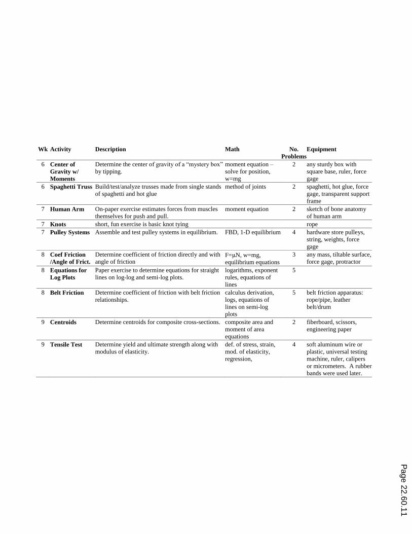
Wk Activity Description Math No.
Problems
Equipment
6 Center of
Gravity w/
Moments
Determine the center of gravity of a “mystery box”
by tipping.
moment equation –
solve for position,
w=mg
2 any sturdy box with
square base, ruler, force
gage
6 Spaghetti Truss Build/test/analyze trusses made from single stands
of spaghetti and hot glue
method of joints 2 spaghetti, hot glue, force
gage, transparent support
frame
7 Human Arm On-paper exercise estimates forces from muscles
themselves for push and pull.
moment equation 2 sketch of bone anatomy
of human arm
7 Knots short, fun exercise is basic knot tying rope
7 Pulley Systems Assemble and test pulley systems in equilibrium. FBD, 1-D equilibrium 4 hardware store pulleys,
string, weights, force
gage
8 Coef Friction
/Angle of Frict.
Determine coefficient of friction directly and with
angle of friction F= N, w=mg,
equilibrium equations
3 any mass, tiltable surface,
force gage, protractor
8 Equations for
Log Plots
Paper exercise to determine equations for straight
lines on log-log and semi-log plots.
logarithms, exponent
rules, equations of
lines
5
8 Belt Friction Determine coefficient of friction with belt friction
relationships.
calculus derivation,
logs, equations of
lines on semi-log
plots
5 belt friction apparatus:
rope/pipe, leather
belt/drum
9 Centroids Determine centroids for composite cross-sections. composite area and
moment of area
equations
2 fiberboard, scissors,
engineering paper
9 Tensile Test Determine yield and ultimate strength along with
modulus of elasticity.
def. of stress, strain,
mod. of elasticity,
regression,
4 soft aluminum wire or
plastic, universal testing
machine, ruler, calipers
or micrometers. A rubber
bands were used later.
Page 22.60.11
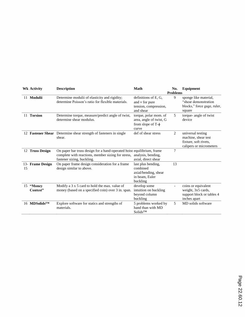
Wk Activity Description Math No.
Problems
Equipment
11 Modulii Determine modulii of elasticity and rigidity;
determine Poisson‟s ratio for flexible materials.
definitions of E, G,
and for pure
tension, compression,
and shear
9 sponge like material,
“shear demonstration
blocks,” force gage, ruler,
square
11 Torsion Determine torque, measure/predict angle of twist,
determine shear modulus.
torque, polar mom. of
area, angle of twist, G
from slope of T-
curve
5 torque- angle of twist
device
12 Fastener Shear Determine shear strength of fasteners in single
shear.
def of shear stress 2 universal testing
machine, shear test
fixture, soft rivets,
calipers or micrometers
12 Truss Design On paper bar truss design for a hand-operated hoist
complete with reactions, member sizing for stress,
fastener sizing, buckling.
equilibrium, frame
analysis, bending,
axial, direct shear
7
13-
15 Frame Design On paper frame design consideration for a frame
design similar to above.
last plus bending,
combined
axial/bending, shear
in beam, Euler
buckling
13
15 “Money
Contest”
Modify a 3 x 5 card to hold the max. value of
money (based on a specified coin) over 3 in. span.
develop some
intuition on buckling
beyond column
buckling
- coins or equivalent
weight, 3x5 cards,
support block or tables 4
inches apart
16 MDSolids™ Explore software for statics and strengths of
materials.
5 problems worked by
hand than with MD
Solids™
5 MD solids software
Page 22.60.12
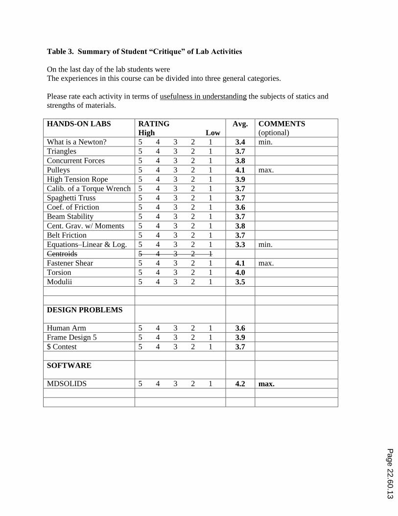
Table 3. Summary of Student “Critique” of Lab Activities
On the last day of the lab students were
The experiences in this course can be divided into three general categories.
Please rate each activity in terms of usefulness in understanding the subjects of statics and
strengths of materials.
HANDS-ON LABS
RATING
High Low
Avg. COMMENTS (optional)
What is a Newton? 5 4 3 2 1 3.4 min.
Triangles 5 4 3 2 1 3.7
Concurrent Forces 5 4 3 2 1 3.8
Pulleys 5 4 3 2 1 4.1 max.
High Tension Rope 5 4 3 2 1 3.9
Calib. of a Torque Wrench 5 4 3 2 1 3.7
Spaghetti Truss 5 4 3 2 1 3.7
Coef. of Friction 5 4 3 2 1 3.6
Beam Stability 5 4 3 2 1 3.7
Cent. Grav. w/ Moments 5 4 3 2 1 3.8
Belt Friction 5 4 3 2 1 3.7
Equations–Linear & Log. 5 4 3 2 1 3.3 min.
Centroids 5 4 3 2 1
Fastener Shear 5 4 3 2 1 4.1 max.
Torsion 5 4 3 2 1 4.0
Modulii 5 4 3 2 1 3.5
DESIGN PROBLEMS
Human Arm 5 4 3 2 1 3.6
Frame Design 5 5 4 3 2 1 3.9
$ Contest 5 4 3 2 1 3.7
SOFTWARE
MDSOLIDS 5 4 3 2 1 4.2 max.
Page 22.60.13