Embed Size (px)
Citation preview

PHOTONIC SENSORS / Vol. 6, No. 2, 2016: 107‒114
A Low-Cost, Portable Optical Sensing System With Wireless Communication Compatible of Real-Time and Remote
Detection of Dissolved Ammonia
Shijie DENG1*, William DOHERTY2, Michael AP MCAULIFFE1, Urszula SALAJ-KOSLA3, Liam LEWIS1, and Guillaume HUYET1,2
1Centre for Advanced Photonics & Process Analysis, Cork Institute of Technology and Tyndall National Institute, Cork,
Ireland 2Department of Physical Science, Cork Institute of Technology, Cork, Ireland 3Department of Chemical and Environmental Science, University of Limerick, Limerick, Ireland *Corresponding author: Shijie DENG E-mail: [email protected]
Abstract: A low-cost and portable optical chemical sensor based ammonia sensing system that is capable of detecting dissolved ammonia up to 5 ppm is presented. In the system, an optical chemical sensor is designed and fabricated for sensing dissolved ammonia concentrations. The sensor uses eosin as the fluorescence dye which is immobilized on the glass substrate by a gas-permeable protection layer. A compact module is developed to hold the optical components, and a battery powered micro-controller system is designed to read out and process the data measured. The system operates without the requirement of laboratory instruments that makes it cost effective and highly portable. Moreover, the calculated results in the system can be transmitted to a PC wirelessly, which allows the remote and real-time monitoring of dissolved ammonia.
Keywords: Ammonia sensing; optical chemical sensor; portable optical sensing system; remote sensing
Citation: Shijie DENG, William DOHERTY, Michael AP MCAULIFFE, Urszula SALAJ-KOSLA, Liam LEWIS, and Guillaume HUYET, “A Low-Cost, Portable Optical Sensing System With Wireless Communication Compatible of Real-Time and Remote Detection of Dissolved Ammonia,” Photonic Sensors, 2016, 6(2): 107–114.
1. Introduction
Dissolved ammonia is an environmental toxicant that is especially problematic for aquatic organisms. Ammonia (NH3) accumulates easily in aquatic systems because it is a natural byproduct of fish metabolism. All animals excrete some waste in the process of metabolizing food into the energy, nutrients, and proteins they use for survival and growth. For fish, the principal metabolic waste product is ammonia. Because it is continuously excreted and potentially lethal, successful
aquaculture operations must therefore incorporate methods to detect and eliminate ammonia before it can accumulate and harm the aquatic life [1, 2]. As a result, there is a real requirement to develop a cost effective and low maintenance system to allow for continuous monitoring of dissolved ammonia concentrations in aquatic environments.
Advances in optical chemical sensors including sensitive, highly selective, easy to miniaturize, electrical, and magnetic interference-free, reference electrode independent and operational in varied environments (e.g. air or liquid) have allowed them
Received: 30 September 2015 / Revised: 8 March 2016 © The Author(s) 2016. This article is published with open access at Springerlink.com DOI: 10.1007/s13320-016-0291-2 Article type: Regular

Photonic Sensors
108
to be used in a wide range of applications such as medical application, environmental and pharmaceutical analysis, and process control [3‒6]. In addition, the wide availability of the miniature photo-detectors and light sources and the broad usage of optical fibers make the optical chemical sensors very attractive for applications requiring portable and compact sensing solutions. In this work, to develop a portable ammonia sensing system, it is decided to design an optical chemical sensor for the detection of ammonia in the liquid.
A small number of optical chemical sensors based ammonia sensing systems have been developed for the detection of dissolved ammonia [7‒10]. However, those systems require laboratory instruments to operate (e.g. laser source for incident light and a spectrometer or charge-coupled device (CCD)/color camera for sensor results readout). This makes them bulky and expensive, which limits the portability of the device.
In this work, an optical chemical sensor based ammonia sensing system that operates independently of laboratory instruments is developed. It is able to detect dissolved ammonia up to 5 ppm and a lower detection limit of 0.1 ppm is achieved with longer response time. In the system, an optical chemical sensor is developed and used for
sensing dissolved ammonia. Eosin is used as the fluorescence dye which is immobilized on a glass substrate by a gas-permeable protection layer. A compact module is designed for housing the optical components, and a battery powered micro-controller based circuit is designed to control the incident light signal from the light-emitting diode (LED) and read out the fluorescence signal from the sensor. This makes the system highly portable and enhances its usefulness for compact applications. Moreover, the system allows users to transmit the measurement data to a PC through the wireless transceivers that makes it possible for real-time and remote monitoring.
2. System description
Figure 1 shows the block diagram of the ammonia sensing system developed, which consists of two main parts: A. the optical components and sensor module, which includes the optical ammonia sensor, an LED, a photo-detector, optical filters, and the holder for the components; B. the battery powered micro-controller based printed circuit board (PCB), which is used to modulate the light signal from the LED, process the fluorescence signal collected by the detector and transmit the data to a PC through the wireless transceivers.
Ammonia sensor
Optical components & sensor module
Detector
LED
A B
Fluorescence signal
Power & modulation signal
Micro-controller based PCB
Micro-controller
Power management
RF transceiver
RF transceiver board
USB cable PC & Labview
(data collection and display)
Fig. 1 Block diagram of the ammonia detection system. A and B highlight the optical and sensor module and the micro-controller based PCB, respectively.

Shijie DENG et al.: A Low-Cost, Portable Optical Sensing System With Wireless Communication Compatible of Real-Time and Remote Detection of Dissolved Ammonia
109
2.1 Development of optical ammonia sensor
Ammonia (NH3) is an essential nutrient for plant
and is not accessible in its molecular form. Bacteria
can convert the dissolved ammonia to nitrite ( 2NO )
and nitrates ( 3NO ) which can then be used by
plants, a process known as “fixing”. On interacting
with water, ammonia is in equilibrium with
ammonium ion and hydroxide ion as shown in (1):
3 2NH H O +4NH OH . (1)
The equilibrium lies to the right, meaning the
vast majority of nitrogen exists in the ammonium
ion form, rather than the ammonia form. In the
ammonium form, it is quite harmless, and larger
concentrations can be supported.
However, this equilibrium position is dependent
on the pH of the system. Changes in pH can have a
detrimental effect on the system. Given that the
dissociation constant KA of a system is by definition
constant and applying Le Châtelier’s principle to the
following equation, the effect of pH change can be
seen. The dissociation constant of
ammonium-ammonia system can be seen in (2) and
(3): +4NH 3NH H (2)
3
+4
NH H=
NHAK
. (3)
If the pH increases, effectively there are less ions.
The system, which can be considered originally in
equilibrium, has been disturbed, and will rearrange
the distribution of concentration of components of
the reaction so as to minimize the effects of the
disturbance, i.e. AK must be kept constant. This is
achieved by producing more ions, which also
produces more 3NH . Therefore, increasing the pH
releases more 3NH into the system.
The ammonia sensor designed in this work is
based on the change in optical properties associated
with a change in pH. To achieve this, a three-layer
sensor is developed which consists of a solid inert
support, a pH sensitive matrix, and a gas-permeable
protection layer (see Fig. 2). Supports used are glass
microscope slides. The pH dye chosen is eosin
which is a fluorescent dye with the advantage of
having a low fluorescent state in low pH conditions
and higher fluorescence in higher pH conditions
[pH>3.0, greater than the pKa (acid dissociation
constant at logarithmic scale) of eosin]. It has an
absorption maximum at 517 nm and an emission
maximum at 538 nm [11].
Spin coat membrane
Eosin layer Substrate Gas membrane
Spin coat eosin
Fig. 2 Fabrication of the ammonia sensor.
The sensing film is comprised of eosin (1 mM),
microcrystalline cellulose (MCC) (5% w/w), and
methylsulfonic acid (MSA) (0.7 M) dissolved in a
99.5:1 acetone: water mixture. MCC is hygroscopic
and will absorb moisture allowing a localized
aqueous-type environment to form. The eosin is also
absorbed in this aqueous-type environment and can
respond to changes in the pH surrounding it. MSA
(pKa = ‒1.9) is used to ensure that the local pH is
below the pKa (2.9) of eosin. This protonates eosin
and keeps it in the low-fluorescent state. Upon
spin-coating (600 rpm, 50 s), the solvent evaporates
readily leaving a thin (70 micron) sensor film on the
support. The sensor film is left to dry at room
temperature for 24 hours and is then placed
overnight in 0.7 M MSA solution to ensure
protonation of the eosin dye.
To prevent the sensor film from sensing the bulk
solution pH, a gas permeable silicone layer
(25% w/w in n-heptane) is spin coated (1200 rpm,
50 s) on top (100 micron nominal). Dissolved
ammonia gas can diffuse through this layer, and ions
and other liquid species cannot cross this
gas-permeable membrane. In this manner, the sensor
measures the local pH on the film side of the
Photonic Sensors
110
membrane and not the bulk solution pH outside the
membrane.
One chemical pathway can be thought of as follows. This ammonia reacts with the water surrounding the eosin and MCC to form ammonium ions and hydroxide ions. This raises the local pH resulting in a change from the low-fluorescent to the high-fluorescent state.
+3( g) 3 (g ) 2 (l) 4 (aq ) (aq )NH diffuseNH H O NH OH
-+ +bulk sensor
(4)
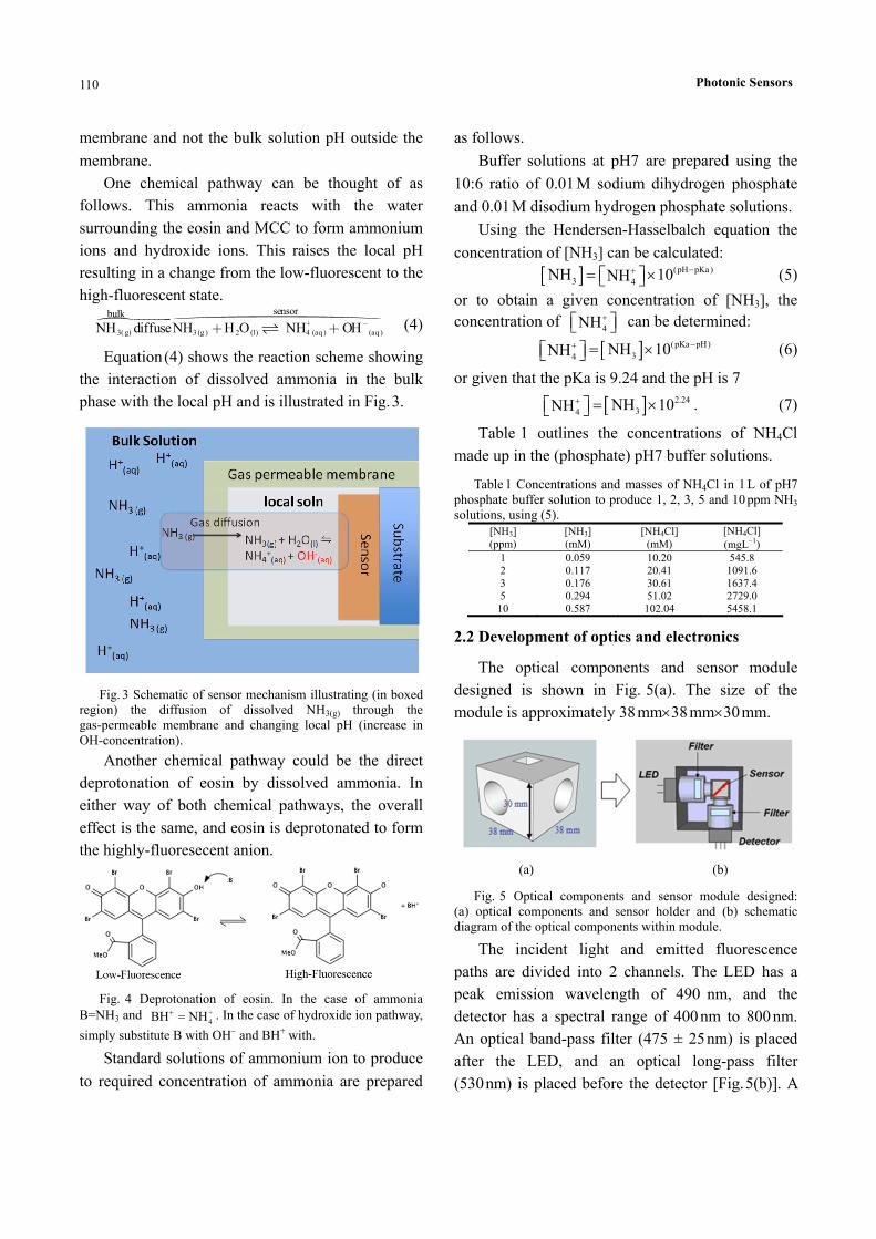
Equation (4) shows the reaction scheme showing the interaction of dissolved ammonia in the bulk phase with the local pH and is illustrated in Fig. 3.
Fig. 3 Schematic of sensor mechanism illustrating (in boxed region) the diffusion of dissolved NH3(g) through the gas-permeable membrane and changing local pH (increase in OH-concentration).
Another chemical pathway could be the direct deprotonation of eosin by dissolved ammonia. In either way of both chemical pathways, the overall effect is the same, and eosin is deprotonated to form the highly-fluoresecent anion.
Fig. 4 Deprotonation of eosin. In the case of ammonia
B=NH3 and +4BH NH . In the case of hydroxide ion pathway,
simply substitute B with OH and BH+ with.
Standard solutions of ammonium ion to produce
to required concentration of ammonia are prepared
as follows.
Buffer solutions at pH7 are prepared using the
10:6 ratio of 0.01 M sodium dihydrogen phosphate
and 0.01 M disodium hydrogen phosphate solutions.
Using the Hendersen-Hasselbalch equation the
concentration of [NH3] can be calculated:
(pH pKa)3 4
NH 10NH (5)
or to obtain a given concentration of [NH3], the concentration of
4NH can be determined:
(pKa pH)34
NH 10NH (6)
or given that the pKa is 9.24 and the pH is 7
2.2434
NH 10NH . (7)
Table 1 outlines the concentrations of NH4Cl
made up in the (phosphate) pH7 buffer solutions.
Table 1 Concentrations and masses of NH4Cl in 1 L of pH7 phosphate buffer solution to produce 1, 2, 3, 5 and 10 ppm NH3 solutions, using (5).
[NH3] (ppm)
[NH3] (mM)
[NH4Cl] (mM)
[NH4Cl] (mgL1)
1 0.059 10.20 545.8 2 0.117 20.41 1091.6 3 0.176 30.61 1637.4 5 0.294 51.02 2729.0
10 0.587 102.04 5458.1
2.2 Development of optics and electronics
The optical components and sensor module designed is shown in Fig. 5(a). The size of the
module is approximately 38 mm38 mm30 mm.
(a) (b)
Fig. 5 Optical components and sensor module designed: (a) optical components and sensor holder and (b) schematic diagram of the optical components within module.
The incident light and emitted fluorescence paths are divided into 2 channels. The LED has a peak emission wavelength of 490 nm, and the detector has a spectral range of 400 nm to 800 nm.
An optical band-pass filter (475 ± 25 nm) is placed after the LED, and an optical long-pass filter (530 nm) is placed before the detector [Fig. 5(b)]. A
Shijie DENG et al.: A Low-Cost, Portable Optical Sensing System With Wireless Communication Compatible of Real-Time and Remote Detection of Dissolved Ammonia
111
hole (13 mm13 mm30 mm) in the module allows water to flow through to fill the region where the ammonia sensor is fixed across the diagonal. For this work, a cuvette is used with the sensor placed
within a fixed volume of water and varying amounts of ammonia solution added to the water. The position of the ammonia sensor is fixed within the
cuvette.
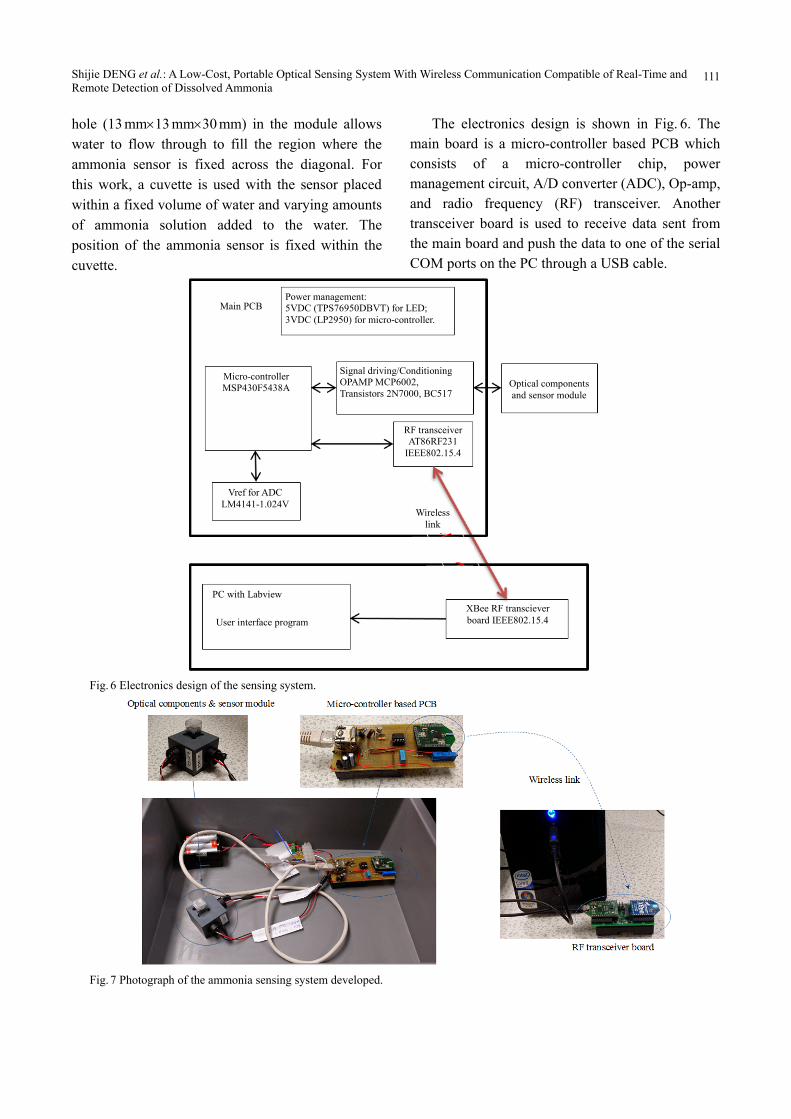
The electronics design is shown in Fig. 6. The main board is a micro-controller based PCB which consists of a micro-controller chip, power management circuit, A/D converter (ADC), Op-amp, and radio frequency (RF) transceiver. Another transceiver board is used to receive data sent from the main board and push the data to one of the serial COM ports on the PC through a USB cable.
Main PCB Power management: 5VDC (TPS76950DBVT) for LED; 3VDC (LP2950) for micro-controller.
Micro-controller MSP430F5438A
Vref for ADC LM4141-1.024V
PC with Labview
User interface program
XBee RF transciever board IEEE802.15.4
Signal driving/Conditioning OPAMP MCP6002, Transistors 2N7000, BC517
RF transceiverAT86RF231
IEEE802.15.4
Optical components and sensor module
Wireless link
Fig. 6 Electronics design of the sensing system.
Fig. 7 Photograph of the ammonia sensing system developed.
Photonic Sensors
112
To avoid photo bleaching, the micro-controller is
programmed to modulate the excitation light from
the LED. The LED is on for 400 micro-seconds in
every 15 s. The photodiode detects the fluorescence
signal emitted from the ammonia sensor, which is
collected by the micro-controller through an A/D
converter. The micro-controller then calculates the
peak-to-peak (pk-pk) amplitude and sends the
results through an RF transceiver on the board to a
second RF transceiver that transmits the data to a PC
through a USB cable. The results can be displayed
using a custom-written Labview routine on the PC.
3. Experimental results
A photograph of the system developed is shown
in Fig. 7. The system is powered by 3 AA batteries,
and the measurement dataare transmitted wirelessly
to a PC using RF transceivers and processed using a
custom-written Labview routine.
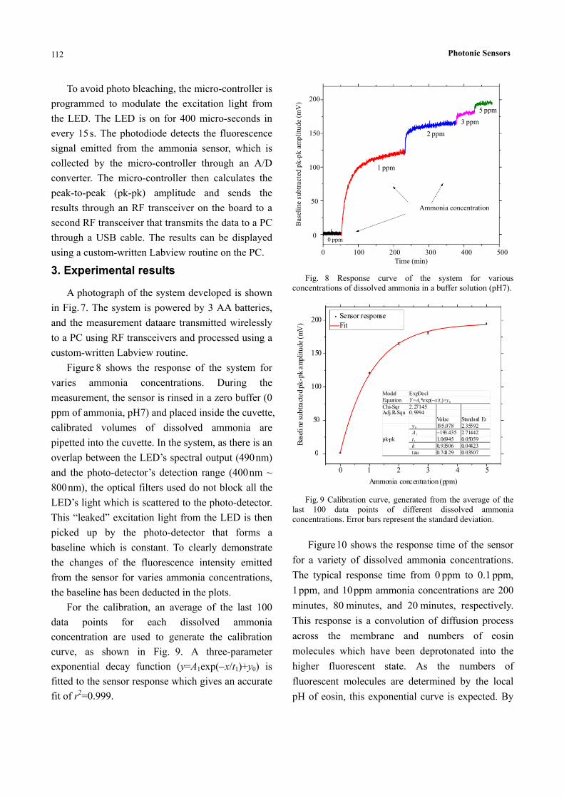
Figure 8 shows the response of the system for
varies ammonia concentrations. During the
measurement, the sensor is rinsed in a zero buffer (0
ppm of ammonia, pH7) and placed inside the cuvette,
calibrated volumes of dissolved ammonia are
pipetted into the cuvette. In the system, as there is an
overlap between the LED’s spectral output (490 nm)
and the photo-detector’s detection range (400 nm ~
800 nm), the optical filters used do not block all the
LED’s light which is scattered to the photo-detector.
This “leaked” excitation light from the LED is then
picked up by the photo-detector that forms a
baseline which is constant. To clearly demonstrate
the changes of the fluorescence intensity emitted
from the sensor for varies ammonia concentrations,
the baseline has been deducted in the plots.
For the calibration, an average of the last 100
data points for each dissolved ammonia
concentration are used to generate the calibration
curve, as shown in Fig. 9. A three-parameter
exponential decay function (y=A1exp(x/t1)+y0) is
fitted to the sensor response which gives an accurate
fit of r2=0.999.
500
1 ppm
Time (min) 400300 200 1000
0
50
100
150
200
Bas
elin
e su
btra
cted
pk-
pk a
mpl
itud
e (m
V)
0 ppm
2 ppm
3 ppm
5 ppm
Ammonia concentration
Fig. 8 Response curve of the system for various concentrations of dissolved ammonia in a buffer solution (pH7).
5
Ammonia concentration (ppm)
4 3 2 10
0
50
100
150
200
Bas
elin
e su
btra
cted
pk-
pk a
mpl
itude
(m
V)
Sensor responseFit
Model ExpDec1 Equation Y=A1*exp(x/t1)+y0 Chi-Sqr 2.27145 Adj.R-Squ 0.9994 Value Standard Er
y0 195.078 2.35592 A1 193.435 2.71442 t1 1.06945 0.05059 k 0.93506 0.04423
pk-pk
tau 0.74129 0.03507
Fig. 9 Calibration curve, generated from the average of the last 100 data points of different dissolved ammonia concentrations. Error bars represent the standard deviation.
Figure 10 shows the response time of the sensor
for a variety of dissolved ammonia concentrations.
The typical response time from 0 ppm to 0.1 ppm,
1 ppm, and 10 ppm ammonia concentrations are 200
minutes, 80 minutes, and 20 minutes, respectively.
This response is a convolution of diffusion process
across the membrane and numbers of eosin
molecules which have been deprotonated into the
higher fluorescent state. As the numbers of
fluorescent molecules are determined by the local
pH of eosin, this exponential curve is expected. By

Shijie DENG et al.: A Low-Cost, Portable Optical Sensing System With Wireless Communication Compatible of Real-Time and Remote Detection of Dissolved Ammonia
113
varying the concentration of eosin and/or the amount
of MSA, the response curve can be changed to give
a stronger response or a more sensitive response.
Larger concentrations of MSA would require larger
concentrations of ammonia to affect the requisite
change in local pH to enable a fluorescent state to
form. Hence the applicable sensing range can be
fine-tuned. Response time is mainly due to diffusion
controlled process across the gas-permeable
membrane. To achieve faster time, a thinner and
structurally complete membrane is required.
(a) (b) (c)
Fig. 10 Response time of the sensor for varies dissolved ammonia concentrations: (a) 0.1 ppm, (b) 1 ppm, and (c) 10 ppm.
4. Conclusions
In this work, an optical chemical sensor based
ammonia detection system is developed, which is
capable of detecting dissolved ammonia up to 5 ppm.
To fabricate the optical chemical sensor in the
system, eosin is used as the fluorescence dye which
is immobilized on the glass substrate by a
gas-permeable protection layer. The sensing system
uses a compact module for housing the optical
components and a battery powered micro-controller
based circuit for the control of the incident light
signal from the LED and readout of the fluorescence
signal from the sensor. This allows the system to
operate independently of the laboratory instruments
that makes it low-cost and highly portable, and
enables its usefulness for compact applications.
Moreover, the system can communicate with a PC
through wireless transceivers that makes it possible
for real-time and remote monitoring of dissolved
ammonia.
Acknowledgment
This work was supported by Enterprise Ireland
(EI) and Science Foundation Ireland (SFI). The
authors would like to thank Pat O'Leary from
Faaltech Technologies Ltd and Jean-Michel
Rubillon from Cork Institute of Technology for their
support and help.
Open Access This article is distributed under the terms of the Creative Commons Attribution 4.0 International License (http://creativecommons.org/licenses/by/4.0/), which permits unrestricted use, distribution, and reproduction in any medium, provided you give appropriate credit to the original author(s) and the source, provide a link to the Creative Commons license, and indicate if changes were made.
References
[1] L. M. Nollet, Handbook of water analysis. Japan: Food Science and Technology, 2000.
[2] B. Timmer, W. Olthuis, and A. V. D. Berg, “Ammonia sensors and their applications—a review,” Sensors and Actuators B: Chemical, 2005,

Photonic Sensors
114
107(2): 666‒677. [3] C. McDonagh, C. S. Burke, and B. D. MacCraith,
“Optical chemical sensors,” Chemical Reviews, 2008, 108(2): 400‒422.
[4] O. S. Wolfbeis, “Fiber-optic chemical sensors and biosensors,” Analytical Chemistry, 2008, 80(12): 4269‒4283.
[5] A. R. Firooz, M. Movahedi, and A. A. Ensafi, “Selective and sensitive optical chemical sensor for the determination of Hg (II) ions based on tetrathia-12-crown-4 and chromoionophore I,” Sensors and Actuators B: Chemical, 2012, 171‒172(8): 492‒498.
[6] Y. Wang, B. Li, L. Zhang, L. Liu, O. Zuo, and P. Li, “A highly selective regenerable optical sensor for detection of mercury (II) ion in water using organic–inorganic hybrid nanomaterials containing pyrene,” New Journal of Chemistry, 2010, 34(9):
1946‒1953. [7] K. T. Lau, S. Edwards, and D. Diamond, “Solid-state
ammonia sensor based on Berthelot’s reaction,” Sensors and Actuators B: Chemical, 2004, 98(1): 12‒17.
[8] S. Tao, L. Xu, and J. C. Fanguy, “Optical fiber ammonia sensing probes using reagent immobilized porous silica coating as transducers,” Sensors and Actuators B: Chemical, 2006, 115(1): 158‒163.
[9] T. Abel, B. Ungerböck, I. Klimant, and T. Mayr, “Fast responsive, optical trace level ammonia sensor for environmental monitoring,” Chemistry Central Journal, 2012, 6(1): 21777‒21778.
[10] K. Waich, T. Mayr, and I. Kilmant, “Fluorescence sensors for trace monitoring of dissolved ammonia,” Talanta, 2008, 77(1): 66‒72.
[11] R.W. Sabnis, Handbook of biological dyes and stains. New York: Wiley, 2010.


![Review Article - Hindawi Publishing Corporationdownloads.hindawi.com/archive/2012/751686.pdf · as strength, electrical properties, and optical characteristics [10]. Moreover, their](https://img.pdfslide.us/doc/110x75/5ec09bd57628b75ca37e4ce4/review-article-hindawi-publishing-as-strength-electrical-properties-and-optical.jpg)