Embed Size (px)
Citation preview
A Log Buffer-Based Flash Translation LayerUsing Fully-Associative Sector Translation
SANG-WON LEE
Sungkyunkwan University
DONG-JOO PARK
Soongsil University
TAE-SUN CHUNG
Ajou University
DONG-HO LEE
Hanyang University
SANGWON PARK
Hankook University of Foreign Studies
and
HA-JOO SONG
Pukyong National University
Flash memory is being rapidly deployed as data storage for mobile devices such as PDAs, MP3
players, mobile phones, and digital cameras, mainly because of its low electronic power, nonvolatile
storage, high performance, physical stability, and portability. One disadvantage of flash memory
is that prewritten data cannot be dynamically overwritten. Before overwriting prewritten data,
a time-consuming erase operation on the used blocks must precede, which significantly degrades
This work was supported in part by MIC & IITA through IT Leading R&D Support Project, in part
by MIC & IITA through Oversea Post-Doctoral Support Program 2005, in part by the Ministry
of Information and Communication, Korea under the ITRC support program supervised by the
Institute of Information Technology Assessment, IITA-2005-(C1090-0501-0019), and also supported
in part by Seoul R&D Program(10660).
Authors’ addresses: Sang-Won Lee, School of Information and Communications Engineering,
Sungkyunkwan University, Suwon 440-746, Korea; email: [email protected]; Dong-Joo Park, School
of Computing, Soongsil University, Seoul 156-743, Korea; email: [email protected]; Tae-Sun
Chung, College of Information Technology, Ajou University, Suwon 443-749, Korea; email:
[email protected]; Dong-Ho Lee, Department of Computer Science and Engineering, Hanyang
University, Ansan 426-791, Korea; email: [email protected]; Sangwon Park, Informa-
tion Communication Engineering, Hankook University of Foreign Studies, Yongin 449-791, Korea;
email: [email protected]; Ha-Joo Song, Division of Electronic, Computer, and Telecommunication,
Pukyong National University, Busan 608-737, Korea; email: [email protected].
Permission to make digital or hard copies of part or all of this work for personal or classroom use is
granted without fee provided that copies are not made or distributed for profit or direct commercial
advantage and that copies show this notice on the first page or initial screen of a display along
with the full citation. Copyrights for components of this work owned by others than ACM must be
honored. Abstracting with credit is permitted. To copy otherwise, to republish, to post on servers,
to redistribute to lists, or to use any component of this work in other works requires prior specific
permission and/or a fee. Permissions may be requested from Publications Dept., ACM, Inc., 2 Penn
Plaza, Suite 701, New York, NY 10121-0701 USA, fax +1 (212) 869-0481, or [email protected]© 2007 ACM 1539-9087/2007/07-ART18 $5.00 DOI 10.1145/1275986.1275990 http://doi.acm.org/
10.1145/1275986.1275990
ACM Transactions on Embedded Computing Systems, Vol. 6, No. 3, Article 18, Publication date: July 2007.
2 • S.-W. Lee et al.
the overall write performance of flash memory. In order to solve this “erase-before-write” problem,
the flash memory controller can be integrated with a software module, called “flash translation
layer (FTL).” Among many FTL schemes available, the log block buffer scheme is considered to be
optimum. With this scheme, a small number of log blocks, a kind of write buffer, can improve the
performance of write operations by reducing the number of erase operations. However, this scheme
can suffer from low space utilization of log blocks. In this paper, we show that there is much room
for performance improvement in the log buffer block scheme, and propose an enhanced log block
buffer scheme, called FAST (full associative sector translation). Our FAST scheme improves the
space utilization of log blocks using fully-associative sector translations for the log block sectors.
We also show empirically that our FAST scheme outperforms the pure log block buffer scheme.
Categories and Subject Descriptors: B.3.2 [Design Styles]: Mass Storage; B.4.2 [Input/OutputDevices]: Channels and Controllers; D.4.2 [Storage Management]: Secondary Storage
General Terms: Algorithms, Performance
Additional Key Words and Phrases: Flash memory, FTL, address translation, log blocks, associative
mapping
ACM Reference Format:Lee, S.-W., Park, D.-J., Chung, T.-S., Lee, D.-H., Park, S., and Song, H.-J. 2007. A log buffer-
based flash translation layer using fully-associative sector translation. ACM Trans. Embedd.
Comput. Syst. 6, 3, Article 18 (July 2007), 27 pages. DOI = 10.1145/1275986.1275990
http://doi.acm.org/ 10.1145/1275986.1275990
1. INTRODUCTION
Flash memory is being rapidly deployed as data storage for mobile devices, suchas PDAs, MP3 players, mobile phones, and digital cameras, mainly because of itssmall size, low power consumption, shock resistance, and nonvolatile memory[Douglis et al. 1994; Kim et al. 2002; Gal and Toledo 2005]. Compared to a harddisk with the inevitable mechanical delay in accessing data (that is, seek timeand rotational latency), flash memory provides fast uniform random access. Forexample, the read and write time per sector (typically, 512 bytes) for NAND-flash memory is 15 and 200 μs [Samsung Electronics 2005], respectively, whileeach operation in contemporary hard disks takes around 10 ms [Hennessy andPatterson 2003].
However, flash memory suffers from the write bandwidth problem. A writeoperation is slower than a read operation by an order of magnitude. In addi-tion, a write operation may have to be preceded by a costly erase operationbecause flash memory does not allow overwrites. Unfortunately, write opera-tions are performed in a sector unit, while erase operations are executed ina block unit: usually, one block consists of 32 sectors. An erase operation isvery time-consuming, compared to a write operation; usually, a per-block erasetime is 2 ms [Samsung Electronics 2005]. These inherent characteristics offlash memory reduce write bandwidth, which is the performance bottleneck inflash-based mobile devices.
To relieve this performance bottleneck, it is very important to reduce thenumber of erase operations resulting from write operations. For this, flashmemory vendors have adopted an intermediate software module, called flashtranslation layer (FTL), between the host applications (in general, file systems)and flash memory [Estakhri and Iman 1999; Kim and Lee 2002; Kim et al. 2002;
ACM Transactions on Embedded Computing Systems, Vol. 6, No. 3, Article 18, Publication date: July 2007.
A Log Buffer-Based Flash Translation Layer • 3
Shinohara 1999]. The key role of FTL is to redirect each write request from thehost to an empty area that has been already erased in advance, thus softeningthe limitation of “erase-before-write.” In fact, various FTL algorithms have thusfar been proposed [Chung et al. 2006] and each FTL performance varies con-siderably, depending on the characteristics of the applications. Among them,the log block scheme is well known for excellent performance [Kim et al. 2002].The key idea of this scheme is to maintain a small number of log blocks inflash memory as temporary storage for overwrites. If a collision (an overwrite)occurs at a sector of flash memory, this scheme forwards the new data to anempty sector in the log blocks, instead of erasing the original data block. Sincethese log blocks act as cushions against overwrites, the log block scheme cansignificantly reduce the number of total erase operations.
However, when an overwrite occurs in a data block, the write can be redi-rected only to one log block, which is dedicated for the data block; it cannotbe redirected to other log blocks. For a given overwrite, if there is no log blockdedicated to its data block, a log block should be selected as a victim and re-placed. Thus, if there are a limited number of log blocks, they might have to befrequently replaced for overwrites. Unfortunately, with the log block scheme,the log blocks being replaced usually have many unused sectors. That is, thespace utilization, which can be formally defined as “the percentage of the writ-ten sectors in a log block when it is replaced,” of each log block is low. In ourview, low space utilization degrades the performance of the log block scheme.We need to find out the root cause of low space utilization. For this, we view therole of log blocks from a different perspective. The log blocks in the log blockscheme could be viewed as “a cache for overwrites,” in which a logical sectorto be overwritten can be mapped only to a certain log block—its dedicated logblock. From this viewpoint, the address associativity between logical sectorsand log blocks is of block level. Thus, we call the log block scheme presentedby Kim et al. [2002], the block-associative sector translation (BAST) scheme.We argue that this inflexible block-level associativity in BAST is the primarycause of low space utilization of log blocks.
In this paper, we propose a novel FTL scheme that overcomes the low spaceutilization of BAST. The basic idea is to make the degree of associativity betweenlogical sectors and log blocks higher, thus achieving better write performance.In our scheme, the sector to be overwritten can be placed in any log block andwe, therefore, call our scheme the fully-associative sector translation (FAST)scheme. Hereafter, we denote the FAST scheme and the BAST scheme shortlyas FAST and BAST, respectively. As in the computer architecture’s CPU cacherealm [Hennessy and Patterson 2003], if we view the log blocks as a kind of cachefor write operations and enlarge the associativity, we can reduce the write missratio and, therefore, achieve better FTL performance. The main contributionsof this paper can be divided into three achievements: (1) to identify the majorproblem of BAST and its root cause, (2) to provide the motivation of FAST anddescribe its principal idea and algorithms, and (3) to compare the performanceof FAST and BAST over various configurations. An interesting result is thatFAST can, in a best case, result in more than 50% reduction both in total elapsedtime and in total number of erases.
ACM Transactions on Embedded Computing Systems, Vol. 6, No. 3, Article 18, Publication date: July 2007.

4 • S.-W. Lee et al.
Fig. 1. An anatomy of the NAND flash memory system.
The remainder of this paper is organized as follows. Section 2 gives a briefoverview of flash memory and FTL and explains BAST and its disadvantages.Section 3 describes the key idea of FAST and its algorithms. Section 4 comparesthe performance of our scheme with that of BAST. Finally, Section 5 concludesthis paper and outlines future work.
2. BACKGROUND
In this section, we provide a brief overview of flash memory and FTL, andexplain in detail the principles behind BAST and its disadvantages. The latterpart is somewhat long, but we need to explain BAST in detail because thescheme is not well known in the computer science field.
2.1 Flash Memory and the Flash Translation Layer
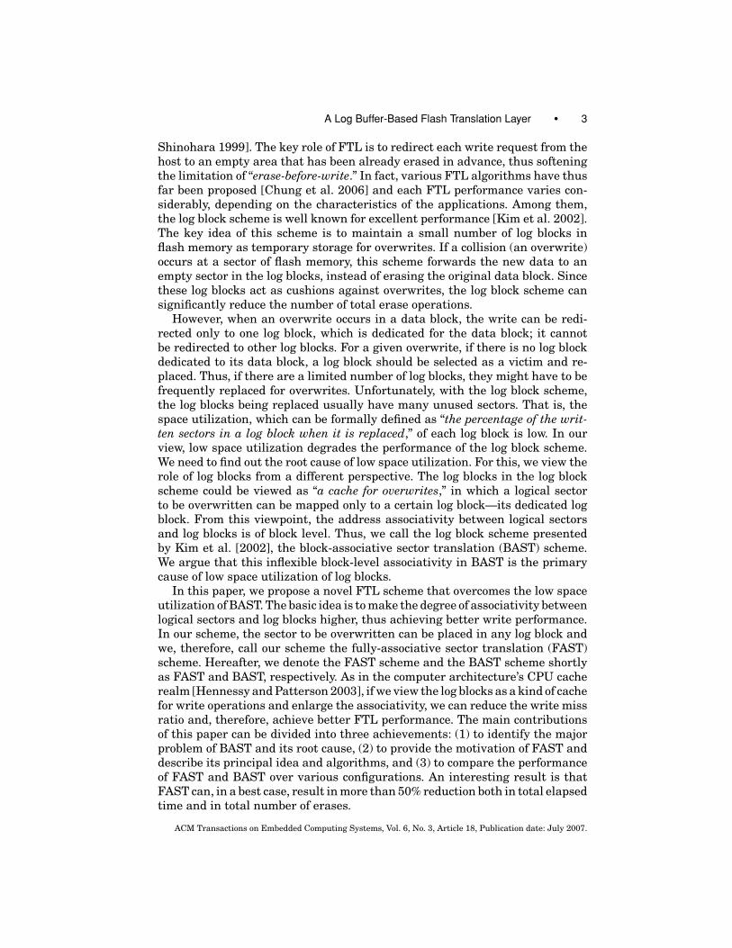
Figure 1 shows the general organization of a NAND-type flash memory system.It consists of one or more flash memory chips, a controller mainly executingFTL codes in ROM, an SRAM maintaining address-mapping information, and aPCMCIA host interface. The host system views flash memory as a hard disklikeblock device and thus issues read or write commands along with “logical” sectoraddresses and data. FTL translates the commands into low-level operations,such as read, write, and erase, using “physical” sector addresses. During theaddress translation, FTL looks up the address-mapping table in SRAM. Whenissuing overwrites, FTL redirects the physical address to an empty location (freespace), thus avoiding erase operations. After finishing an overwrite operation,FTL changes the address-mapping information in SRAM. The outdated blockcan be erased later.
ACM Transactions on Embedded Computing Systems, Vol. 6, No. 3, Article 18, Publication date: July 2007.
A Log Buffer-Based Flash Translation Layer • 5
Besides the address translation from logical sectors to physical sectors,FTL carries out several important functionalities, such as guaranteeing dataconsistency and uniform wear leveling (or so called block recycling). FTL shouldbe able to maintain a consistent state for data and metadata, even when flashmemory encounters an unexpected power outage. For uniform wear leveling,FTL should make every physical block erased as evenly as possible withoutperformance degradation. This functionality of uniform block usage is essen-tial, because there is a physical upper limit on the maximum number of erasesallowed for each block (usually, 100,000 times). If a block is erased above thethreshold, the block may not function correctly, and thus it is marked as invalid.Even though the block may still work, FTL marks it as invalid for the safetyof flash memory. Therefore, if only some physical blocks have been intensivelyerased, they become unusable very quickly, therefore reducing the durability offlash memory. Therefore, FTL need to use all the blocks as uniformly as possi-ble. Even though these kinds of FTL functionalities are important issues, theyare beyond the scope of this paper. In this paper, we focus on the performanceissue of the address-mapping technique.
Let us revisit the address-mapping issue. The mapping between the logi-cal address (which the file system uses to interface with flash memory) andthe physical address (which the flash controller actually uses to store and re-trieve data) can be managed at the sector, block, or hybrid level. In sector-level address mapping, a logical sector can be mapped to any physical sectorin flash memory. In this respect, this mapping approach is very flexible. How-ever, its main disadvantage is that the size of mapping table is too large tobe viable in the current flash memory-packaging technology. For example, letus consider a flash memory of 1 GB size and a sector size of 512 bytes, whichhas 2 million sectors. In this case, the mapping information is too large tomaintain in SRAM. In block-level address mapping, a logical sector addressconsists of a logical block number and an offset. The mapping table main-tains only the mapping information between logical and physical blocks, whilethe offsets of the logical and physical blocks are identical. Therefore, the sizeof block-mapping information is very small, compared to the size of sector-level mapping information. However, this approach also has a serious pitfall:when an overwrite for a logical sector is necessary, the corresponding blockis remapped to a free physical block. The overwrite is done at the same off-set in the new physical block, the other sectors of the original data blockare copied to the new physical block, and ‘finally’ the original physical blockshould be erased. With regard to block-level mapping, this “erase-before-write”problem is an inevitable performance bottleneck, mainly because of the in-flexibility in address mapping. In order to overcome the disadvantages of thesector-level and block-level mapping approaches, several hybrid approaches,including BAST, have been proposed. In the hybrid scheme, in addition to ablock-level mapping table, a sector-level mapping table for a limited numberof blocks is maintained. Thus, it satisfies the size limitations of mapping infor-mation and also mitigates the “erase-before-write” problem drastically. For adetailed discussion on this issue, please refer to Chung et al. [2006] and Gal andToledo [2005].
ACM Transactions on Embedded Computing Systems, Vol. 6, No. 3, Article 18, Publication date: July 2007.

6 • S.-W. Lee et al.
2.2 The BAST Scheme: An Overview
File systems view flash memory as a set of logical sectors—a hard disklike blockdevice. The write function for flash memory can be defined as follows: write(lsn,data), which means “write a given sector data at the logical sector lsn.” Whenreceiving a write request from a file system, FTL finds a physical location inflash memory to write the sector as follows. First, it calculates the logical blocknumber (lbn) using the given lsn.1 It then retrieves the physical block number(pbn) corresponding to the lbn from the block-level mapping table.2 Next, FTLcalculates the offset of the retrieved physical block where the sector data willbe written.3 Finally, it writes the sector data at the resulting offset in the datablock (which is another representation of the physical block).
If the target sector in the data block is already written, FTL writes the givensector data at the same offset in a free-block allocated with the free-block list,and copies all the other written sectors in the data block to the free block.Then, FTL erases the data block and returns it to the free-block list. Whenevera collision between the current write and the previous writes occurs, a largenumber of sector copies and erase operations are inevitable. This occurrence iscalled a merge operation. To address this problem, many FTL techniques havebeen suggested. Among them, BAST is known to be the best FTL technique[Chung et al. 2006]. When encountering a collision, BAST reduces the numberof merge operations by writing data to temporary storage, called log blocks. Inthe following, we describe BAST in detail using an example in Figure 2.
In Figure 2, we assume that the number of sectors per block is four andthe number of log blocks is two. The upper-left part in Figure 2 indicates asequence of writes from the file system, and the upper-center and the upper-right part shows the block-level and the sector-level mapping table, respectively.Both mapping tables are usually maintained in SRAM. When the first writeoperation is called, the BAST algorithm gets data block 10 from the block-levelmapping table using logical block 1 (= 4 div 4). It then stores a given sectorat offset 0 (= 4 mod 4) in data block 10. The second write operation proceedssimilarly. In case of the third write operation, BAST finds a collision in datablock 10, and, therefore, writes the sector at the first sector in a log block (i.e.,pbn = 20), dedicated to logical block 1 from the log block list. In case of thefourth write operation, the sector is directed to the next empty sector in the logblock. The following write operations will generate the second log block (pbn =30) and the sector-level mapping table.
A collision can occur in other data blocks, for example, data block 12 inFigure 2. In this case, since there is no available log block for data block 12,BAST selects, erases, and returns one of the log blocks (we call it a victim logblock). Before returning the victim log block, it needs to merge the victim logblock and its data block: BAST copies the up-to-date sectors from the two blocksto a free block, and exchanges the free block with the original data block. In
1lbn = (lsn div # sectors per block).2BAST maintains both block-level and sector-level address mapping tables, which exist in the data
block and the log block, respectively.3offset = (lsn mod # sectors per block).
ACM Transactions on Embedded Computing Systems, Vol. 6, No. 3, Article 18, Publication date: July 2007.

A Log Buffer-Based Flash Translation Layer • 7
Fig. 2. Processing write operations in the BAST scheme.
addition, BAST updates the block-level mapping table and removes the entrycorresponding to the victim log block from the sector-level mapping table. BASTthen, erases both the victim log block and its data block, and returns them to thefree-block list. If a new log block is necessary, it is allocated from the free-blocklist. One interesting point is that the merge operation can be optimized if thevictim log block satisfies a condition. For example, in Figure 2, all the writes inthe log block of pbn = 30 are sequential and the total number of written sectorsis equal to the capacity of a block. In this case, instead of copying sector datafrom the victim log block to the free block, we can complete a merge operationjust by exchanging the victim log block with its data block; this optimization iscalled a “switch” operation [Kim et al. 2002].
2.3 Another View of the Log Block Scheme: A Cache for Writes
In this section, we see the role of log blocks from another perspective, and thisview will help us to understand the disadvantages of the log block scheme.For this, we would like to briefly explain the principal role of the CPU cacheand its basic functions. Because of the principle of locality in data access ofcomputer programs [Hennessy and Patterson 2003], a small cache combinedwith the memory hierarchy can provide users with a very fast, large, and cheapmemory system (Figure 3a). In this respect, the log blocks in the log blockscheme can also be viewed as “a cache for overwrites” (Figure 3b). In case ofcollisions, we can complete the write operation much faster by writing sectorsin the log blocks (that is, the cache), instead of overwriting its original datablock.
ACM Transactions on Embedded Computing Systems, Vol. 6, No. 3, Article 18, Publication date: July 2007.

8 • S.-W. Lee et al.
Fig. 3. CPU cache versus log blocks: associativity.
As depicted in Figure 3a, there is the associativity issue between memoryand cache regarding how memory blocks are mapped to cache blocks. Thereare various associativity schemes used in computer architecture, includingdirect-mapped, n-way associative, and fully associative approaches [Hennessyand Patterson 2003]. With the direct-mapped approach, a memory block can beplaced only in a dedicated cache block via a mathematical formula, while thefully associative approach allows a block to be placed anywhere in the cache.In terms of the associativity, we could say that the log block scheme takes theblock-associative sector translation approach, because the scheme directs allthe overwrites for one logical block only to its dedicated log block, as depictedin Figure 3c.
2.4 Disadvantages
This block-level associativity of BAST results in two performance problems. Thefirst problem is analogous to the high miss ratio in direct-mapped associativitybetween CPU cache and main memory, which results in the block-thrashing[Hennessy and Patterson 2003]. BAST has a similar block-thrashing problem.If the cache in flash memory (namely, the log blocks) cannot accommodate allcollisions during the execution of a host application (especially, writes for hotblocks in flash memory), BAST will experience numerous capacity misses, thuscausing the block thrashing. For instance, assume that two blocks (and foursectors per each block) are allocated for the cache and that an overwrite pattern
ACM Transactions on Embedded Computing Systems, Vol. 6, No. 3, Article 18, Publication date: July 2007.

A Log Buffer-Based Flash Translation Layer • 9
Fig. 4. Low space utilization in the BAST scheme.
is the sequence “S0, S4, S8, S12, S0, S4, S8, S12,” where Si is the logical sectornumber for each overwrite and the original data of each logical sector is alreadystored in the data block. In addition, we assume that all the original data blocksare already filled. Please note that S0, S4, S8, and S12 come from differentblocks, because each block holds four sectors. For every write, starting fromthe first S8 overwrite, BAST should replace either of the two log blocks. Werefer to this phenomenon as log block thrashing. Each victim replacement willaccompany an expensive merge operation. Moreover, every victim log block inthis example holds only one sector of data when it is replaced; the other threesectors remain empty.
Another performance problem arises from block-level associativity. Assumethat under the same cache above, the overwrite operations for one hot logicalblock occur successively, e.g., the write pattern is the sequence “S0, S2, S1,S3, S1, S0, S2, S3.”4 In BAST, for every fourth write, the log block allocated tothe hot logical block should be merged with its original data block, althoughthe other log block is idle. In summary, when intensive overwrites for one hotblock occur during a given time window, the log block scheme might result inincreased write operations.
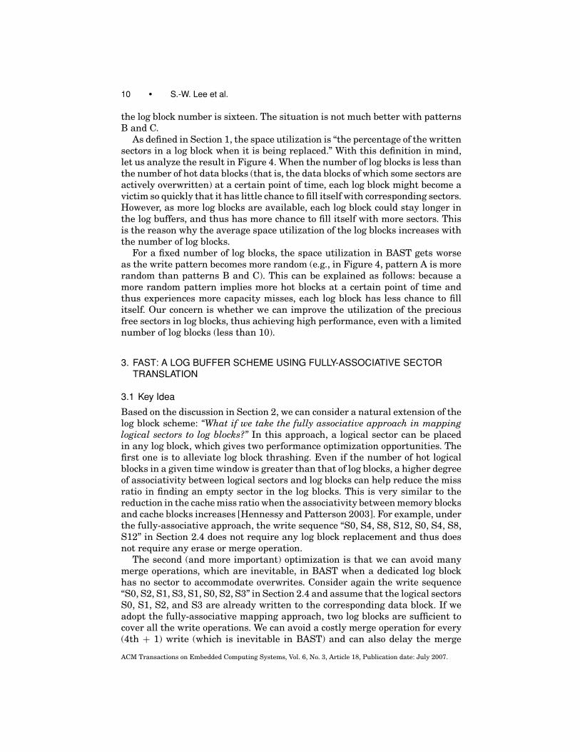
Because of these two problems, the log blocks in BAST would show very lowspace utilization when they are replaced from the log buffer. Each sector in thelog block is a very precious resource in the sense that it might prevent an “erase-before-write” phenomenon if exploited properly. Low space utilization of the logblocks indicates that there is an opportunity for performance improvement inBAST. In order to measure the severity of low space utilization, we simulateBAST over various workloads and calculate the space utilization of the logblocks being replaced. We used three workloads: pattern A of mainly randomwrites generated from a Symbian environment and pattern B and C, mainlyof sequential writes generated from a digital camera. For the experiment, wemeasured the space utilization by increasing the number of log blocks from 4to 64. Figure 4 shows the experimental result for space utilization in BAST. Asshown in the figure, the space utilization for pattern A is under 50%, even when
4The hot logical block number is 0.
ACM Transactions on Embedded Computing Systems, Vol. 6, No. 3, Article 18, Publication date: July 2007.
10 • S.-W. Lee et al.
the log block number is sixteen. The situation is not much better with patternsB and C.
As defined in Section 1, the space utilization is “the percentage of the writtensectors in a log block when it is being replaced.” With this definition in mind,let us analyze the result in Figure 4. When the number of log blocks is less thanthe number of hot data blocks (that is, the data blocks of which some sectors areactively overwritten) at a certain point of time, each log block might become avictim so quickly that it has little chance to fill itself with corresponding sectors.However, as more log blocks are available, each log block could stay longer inthe log buffers, and thus has more chance to fill itself with more sectors. Thisis the reason why the average space utilization of the log blocks increases withthe number of log blocks.
For a fixed number of log blocks, the space utilization in BAST gets worseas the write pattern becomes more random (e.g., in Figure 4, pattern A is morerandom than patterns B and C). This can be explained as follows: because amore random pattern implies more hot blocks at a certain point of time andthus experiences more capacity misses, each log block has less chance to fillitself. Our concern is whether we can improve the utilization of the preciousfree sectors in log blocks, thus achieving high performance, even with a limitednumber of log blocks (less than 10).
3. FAST: A LOG BUFFER SCHEME USING FULLY-ASSOCIATIVE SECTORTRANSLATION
3.1 Key Idea
Based on the discussion in Section 2, we can consider a natural extension of thelog block scheme: “What if we take the fully associative approach in mappinglogical sectors to log blocks?” In this approach, a logical sector can be placedin any log block, which gives two performance optimization opportunities. Thefirst one is to alleviate log block thrashing. Even if the number of hot logicalblocks in a given time window is greater than that of log blocks, a higher degreeof associativity between logical sectors and log blocks can help reduce the missratio in finding an empty sector in the log blocks. This is very similar to thereduction in the cache miss ratio when the associativity between memory blocksand cache blocks increases [Hennessy and Patterson 2003]. For example, underthe fully-associative approach, the write sequence “S0, S4, S8, S12, S0, S4, S8,S12” in Section 2.4 does not require any log block replacement and thus doesnot require any erase or merge operation.
The second (and more important) optimization is that we can avoid manymerge operations, which are inevitable, in BAST when a dedicated log blockhas no sector to accommodate overwrites. Consider again the write sequence“S0, S2, S1, S3, S1, S0, S2, S3” in Section 2.4 and assume that the logical sectorsS0, S1, S2, and S3 are already written to the corresponding data block. If weadopt the fully-associative mapping approach, two log blocks are sufficient tocover all the write operations. We can avoid a costly merge operation for every(4th + 1) write (which is inevitable in BAST) and can also delay the merge
ACM Transactions on Embedded Computing Systems, Vol. 6, No. 3, Article 18, Publication date: July 2007.

A Log Buffer-Based Flash Translation Layer • 11
operations until there is no empty sector in the log blocks. In summary, whenone of the logical blocks is very hot in a given time period, the full associativityapproach can avoid many merge operations.
Even though these optimizations might seem to be naı̈ve, the performanceimpact is considerable. In subsequent sections, the further advantages offull associativity between logical sectors and log blocks will be described indetail.
3.2 The Architecture
The architecture of FAST is analogous to that of BAST. One important differenceis that log blocks in FAST are divided into two areas: one log block is used forsequential writes and the other blocks for random writes. Let us explain thereason why a log block is dedicated for sequential writes. As stated in Section2.2, a switch operation is more efficient than a merge operation. Since mostof the workload traced from flash memory systems contains a large numberof sequential writes, it is likely that many switch operations arise from them.However, since our FAST scheme takes the fully-associative address-mappingapproach, we cannot take advantage of switch operations unless sequentialwrites are handled separately from random writes. That is, if both types ofwrite patterns are intermixed only in a fully associative manner, there is littlechance for switch optimization in FAST. For this reason, FAST keeps a dedicatedlog block for sequential writes. In the subsequent sections, the SW log blockdenotes the log block for sequential writes and the RW log blocks represent thelog blocks for random writes.
The other architectural difference between FAST and BAST is that FASTmaintains separate sector-level mapping tables for the above two types of logblocks. The sector-mapping table for the SW log block keeps information onwhich logical block the current log block corresponds to, and how many sectorsare currently stored in the log block. Meanwhile, a more complex mapping tableis needed for the RW log blocks. This table records which sectors are writtenand the offsets of the RW log blocks. In theory, a sector can be placed on anyRW log block. However, we take a rather simple approach of filling the RW logblocks with sectors in sequence.
This architecture of FAST yields a small overhead in sector read operations,compared to BAST. For every sector read operation in FAST, we should checkwhether the most recent version of the sector exists in the log blocks. You needto note that this check is accomplished by scanning the sector-level mappingtable in SRAM, not by scanning the log blocks. Thus, for every read operationagainst sectors in log blocks, FAST yields the overhead for scanning the sector-level mapping table in SRAM. If we assume 128 MB flash memory with 512byte-sized sectors, there are 256 K sectors. Hence, we need 18 bits to representan lsn (logical sector number), and each entry in sector-level mapping table canbe stored in 4 bytes. If we assume 6 log blocks and each block has 32 sectors,then the total number of entries in sector-level mapping table is 192. If wescan the sector mapping table from the end of the mapping table in order tocheck whether a logical sector is in the table, we need to read 96 entries from
ACM Transactions on Embedded Computing Systems, Vol. 6, No. 3, Article 18, Publication date: July 2007.

12 • S.-W. Lee et al.
SRAM, on average. The contemporary 4-byte read time from SRAM is 10 ns5
[Hennessy and Patterson 2003], and thus the average time of a scan becomes960 ns (about 1 μs), and this overhead is small compared to the read time for asector, which is typically 15 μs [Samsung Electronics 2005]. BAST also has theoverhead of memory scan for sector read operations because they also maintaina sector-level mapping table, as shown in Figure 2, but they need to scan onlythe sector-mapping information of a log block, and not the entire sector-levelmapping table.
Finally, consider the issues of meta-data and data consistency. FAST is ex-actly the same to BAST in managing the block-level mapping table. That is,block-level mapping information is stored in some dedicated blocks of flashmemory, called “map blocks,” and the block-level mapping table is cached inSRAM for the fast lookup of mapping information at runtime [Kim et al. 2002].The consistency between block-mapping tables in SRAM and in flash memorycan be achieved as in BAST. Besides the block-mapping table, FAST maintainsthe sector-mapping table in SRAM. We need to consider how to achieve the con-sistency of a sector-mapping table when we encounter an unexpected power-off.In the earlier FTL schemes, such as M-system [Ban 1995], with sector-level ad-dress mapping, they record the mapping information between a logical sectorand a physical sector in the spare area of the physical sector. From the sector-mapping information in the spare area, the sector mapping table in SRAMis dynamically constructed during the booting time. Our sector-level mappingtable also can be maintained in this way.
3.3 Handling Write Operations
In this subsection, we explain how FAST handles the write operations issuedfrom the file system. As mentioned in Section 3.2, the log blocks in FAST aredivided into two groups: the SW and the RW log blocks. When a collision oc-curs in a specific data block, the corresponding sector is directed to either oftwo groups, as depicted in Figure 5. For every sector to be written, FAST firstexamines whether its insertion into the SW log block will result in a switchoperation. If so, the sector data is appended in the SW log block; otherwise, thedata is written in the RW log block.
If a log block is to be a candidate of switch operation, it must satisfy twoconditions: (1) the lsn at the first offset in the log block is divided by the numberof sectors per block (for example, 4), that is, lsn mod 4 = 0, and (2) the log blockis filled up with the sectors, which are sequentially written from the beginningoffset to the final offset. Thus, FAST directs only the sectors satisfying eithercondition into the SW log block.
When a collision occurs in a data block, the corresponding sector is amongone of three cases in Figure 5, where we assume the number of sectors per
5This value of access time is in case of random access time. Therefore, the average access time
for each of 96 entries, in case of sequential scan, would be much less. In addition, we believe that
several hundred bytes of all the sector-mapping table can be cached in L1 cache of the CPU used
in the FTL controller (e.g., ARM), and the real overhead will be much smaller than the estimated
overhead in this paper.
ACM Transactions on Embedded Computing Systems, Vol. 6, No. 3, Article 18, Publication date: July 2007.
A Log Buffer-Based Flash Translation Layer • 13
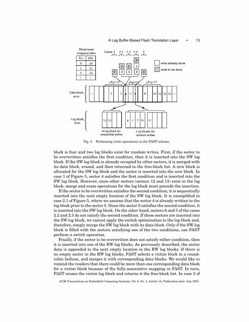
Fig. 5. Performing write operations in the FAST scheme.
block is four and two log blocks exist for random writes. First, if the sector tobe overwritten satisfies the first condition, then it is inserted into the SW logblock. If the SW log block is already occupied by other sectors, it is merged withits data block, erased, and then returned to the free-block list. A new block isallocated for the SW log block and the sector is inserted into the new block. Incase 1 of Figure 5, sector 4 satisfies the first condition and is inserted into theSW log block. However, since other sectors (sectors 12 and 13) exist in the logblock, merge and erase operations for the log block must precede the insertion.
If the sector to be overwritten satisfies the second condition, it is sequentiallyinserted into the next empty location of the SW log block. It is exemplified incase 2.1 of Figure 5, where we assume that the sector 4 is already written to thelog block prior to the sector 5. Since the sector 5 satisfies the second condition, itis inserted into the SW log block. On the other hand, sectors 6 and 5 of the cases2.2 and 2.3 do not satisfy the second condition. If these sectors are inserted intothe SW log block, we cannot apply the switch optimization to the log block and,therefore, simply merge the SW log block with its data block. Only if the SW logblock is filled with the sectors satisfying one of the two conditions, can FASTperform a switch operation.
Finally, if the sector to be overwritten does not satisfy either condition, thenit is inserted into one of the RW log blocks. As previously described, the sectordata is appended to the next empty location in the RW log blocks. If there isno empty sector in the RW log blocks, FAST selects a victim block in a round-robin fashion, and merges it with corresponding data blocks. We would like toremind the readers that there could be more than one corresponding data blockfor a victim block because of the fully-associative mapping in FAST. In turn,FAST erases the victim log block and returns it the free-block list. In case 3 of
ACM Transactions on Embedded Computing Systems, Vol. 6, No. 3, Article 18, Publication date: July 2007.
14 • S.-W. Lee et al.
Figure 5, since the sector 6 does not satisfy either condition, it is inserted intothe RW log blocks.
Figure 6 describes an algorithm of the write operation issued from the filesystem to FTL. In Figure 6, Algorithm 1 shows how the function write() works,which, in turn, calls the function writeToLogblock() in Algorithm 2 when acollision occurs. If there is no collision, the sector data is simply written to itsdata block. Algorithm 2 works as follows. If the given offset is zero, accordingto another condition, FAST executes a switch operation or a merge operationand then stores the given data into the new SW log block, which correspondsto the case 1 of Figure 5. If the offset is not zero, the given sector data isappended to the SW log block (line 13 in Algorithm 2), written to the new blockby the merge operation (line 15 in the Algorithm 2), or put into the RW logblock (line 20 in the algorithm 2). These correspond to cases 2.1, 2.2, 2.3, and3 in Figure 5, respectively. In the next subsection, we describe in detail themerge operation for the log blocks and the victim selection issue for RW logblocks.
3.4 Handling Merge Operations
All three cases mentioned in the previous subsection give rise to a merge orswitch operation. As explained in Section 2.1, a merge operation is achievedin three steps: (1) to copy the up-to-date sectors from the log block and itscorresponding data block to a free-block, (2) to change the mapping information,and (3) to erase both the data block and the log block and return them to the free-block list. In order to optimize a merge operation, it is necessary to minimize thenumber of copy and erase operations. This section describes how FAST handlesswitch operations and merge operations.
� A switch operation in the SW log block: This case is similar to the switchoperation in BAST. If the SW log block is filled up with the sequential sectors,FAST exchanges it with its data block, erases the data block, and returns theerased data block to the free-block list.
� A merge operation in the SW log block: In FAST, there are two caseswhich require a merge operation in the SW log block: (1) when the SW logblock encounters a sector satisfying the first condition in Section 3.3, and (2)when the SW log block encounters a sector violating the second condition ofSection 3.3. The merge operation of FAST is analogous to that of BAST, but wecan apply another optimization technique to the merge operations in FASTwhen the SW log block has a particular state. For instance, in Figure 7a,consider the SW log block containing sectors of S4, −1, S6, −1 where −1indicates “no sector written.” In this case, FAST will copy the data of emptysectors with −1’s (sector 5, in this example) from its original data block,exchange the updated log block with its data block, and, finally, erase thedata block and return the erased data block to the free-block list. Please notethat this optimization is distinct from the switch operation in BAST. Thisoptimization requires a small number of copies and only one erase operation,while the original merge operation requires a sectors-per-block number ofcopies and two erase operations for the SW log block and its original data
ACM Transactions on Embedded Computing Systems, Vol. 6, No. 3, Article 18, Publication date: July 2007.

A Log Buffer-Based Flash Translation Layer • 15
Fig. 6. Write algorithm in FAST.
ACM Transactions on Embedded Computing Systems, Vol. 6, No. 3, Article 18, Publication date: July 2007.

16 • S.-W. Lee et al.
Fig. 7. Performing merge operations in FAST.
block. This optimization could also be applied to BAST, but we first suggestthe technique in this paper.
� A merge operation in the RW log blocks: If no more empty sectors existin the RW log blocks, FAST chooses one of the RW log blocks as victim andmerges the victim block with its corresponding data blocks. The victim se-lection is done in a round-robin fashion. With regard to merge operations inthe RW log blocks, the readers should note that the sectors in a victim mightoriginate from several different logical blocks and, therefore, the number ofmerge operations per a victim block is equal to the number of logical blockscorresponding to the sectors in the victim.6 In FAST, each merge operationper logical block proceeds as follows. First, in order to find all sectors forthe logical block, FAST scans the sector-level mapping table for the RW logblocks. For each sector found, FAST copies the most up-to-date version fromthe RW log blocks to a free-block. Then, FAST marks all the found sectors inthe sector-level mapping table as invalid state (−1). If a sector with invalidstate is encountered in the future victim block, we can ignore the sector, be-cause we know that its up-to-date version is already stored in its data block.Next, FAST selectively fills each empty sector in the free-block with its cor-responding sector in the data block, and, in turn, exchanges the free-blockwith the data block. The data block is erased and returned to the free-blocklist. Finally, after merging all the logical blocks in the victim, FAST erasesthe victim log block itself and returns it to the free-block list. For example, letus consider Figure 7b, where the first log block is a victim. Since the sectorsin the victim block come from two different logical blocks 0 (for S1 and S3)and 2 (for S8 and S10), two merge operations for (S1, S3) and (S8, S10) arerequired. The merge operation for (S1, S3) proceeds as follows: The up-to-date sectors of logical block 0, i.e., sector 1 in the victim block and sectors 2and 3 in the nonvictim log blocks, are copied to a free block. Then, the sector0 in the original data block is copied to the free block. The data block is then
6In contrast, all the sectors in each victim log block in BAST originates from one logical block and,
thus, only one merge operation is required per victim.
ACM Transactions on Embedded Computing Systems, Vol. 6, No. 3, Article 18, Publication date: July 2007.

A Log Buffer-Based Flash Translation Layer • 17
erased and returned to the free-block list. The merge operation for (S8, S10)proceeds similarly; then, the victim log block is erased and returned to thefree-block list.
3.5 An Analytical Comparison to BAST
Before proceeding, we would like to compare BAST and FAST in an analyticalway so that the readers can understand the advantages of FAST more clearly.For this, we will analyze why and how the full associativity in FAST can reducethe number of erase operations, compared to BAST, in various cases, in terms ofthe number of hot data blocks and the number of log blocks. In this subsection,for the brevity of description, we denote the number of hot data blocks as nhb,the number of the log blocks as nlb, and the number of sectors-per-block asnspb. We cover the following four cases: (1) when nhb is equal to nlb, (2) whennhb is one, (3) when nhb is greater than nlb, and (4) when nhb is between oneand nlb. In this subsection, we will not take large sequential write patternsinto considerations, because both BAST and FAST show a similar performancecharacteristic for the patterns and, instead, focus on the random write patterns.In case of FAST, the nlb merely indicates the number of the RW log blocks,except for the SW log block, because we do not consider the sequential writepatterns.
� When nhb is equal to nlb. In this case, BAST and FAST will require nearlythe same number of erase operations. From the perspective of BAST, eachsector to be overwritten has its dedicated log block and requires a merge op-eration only when its dedicated log block is full. Therefore, a merge operationis necessary, on average, in every nspbth sector writes, and a merge will re-sult in two erase operations: one for the data block and the other for the logblock. FAST also requires a merge operation in every nspbth sector writes,that is, when a new log block is full. In order to merge the first victim, FASTneeds the (nlb + 1) erase operations if we assume that the random write pat-terns are uniformly distributed: one for the victim log block and the othersfor all the hot data blocks. However, for each of the following (nlb − 1) victimlog blocks, FAST can complete the merge operations of the victim by erasingonly the victim block, since almost of the sectors were already marked as in-valid during the merge operation of the first victim. Thus, FAST will requireapproximately 2 * nlb erase operations by when the first nlb log blocks aremerged and, thus, on average, each victim replacement requires two eraseoperations, as in BAST.
� When there exists only one hot data block. In an extreme case whereall the sectors to be overwritten come from only one logical block (that is,one hot data block), BAST writes all the sectors only in a dedicated log blockand thus requires a merge operations in every nspbth write, even thoughother log blocks are empty. In contrast, FAST utilizes every log block andthus accepts the sector writes until it all the log blocks are filled. In addition,while merging the first victim block, FAST invalidates all the sectors in otherlog blocks and, thus, it can complete the merge operations of the followingvictim blocks by erasing only the victim block, because all the sectors in the
ACM Transactions on Embedded Computing Systems, Vol. 6, No. 3, Article 18, Publication date: July 2007.
18 • S.-W. Lee et al.
following victims were already marked as invalid during the merge operationof the first victim. Thus, by the time the first nlb log blocks are merged, FASTcan save the (nlb −1) erase operations, compared to BAST. From this, wecould argue that the performance of FAST is scalable to the nlb, because itcan save more erase operations as the nlb increases. In contrast, BAST doesnot benefit from the increased nlb because of its block-level associativity.
� When nhb is greater than nlb. In the case where the number of hot blocksat a certain point of time is greater than nlb, BAST should replace a log blockwhenever a sector without its dedicated log block in the log buffer arrives,and only a small fraction of the victim block is, in most cases, used. That is,the block-level associativity results in log block thrashing and low space uti-lization of the log blocks. In the worst case, each sector to be overwritten mayrequire a victim replacement, which, in turn, requires two erase operations.However, FAST caches the sectors to be overwritten in a new log block untilit is full. When replacing the first victim block, FAST might require the (nspb+1) erase operations, at most: one for the victim block and the others for thenspb different data blocks. In a case where the nhb is less than the nspb, thenumber of erase operation will be nhb plus one. As in case of only one hotdata block, while merging the first victim block, FAST will invalidate mostof the sectors in other log blocks and, thus, complete the merge operationsof the following (nlb – 1) log blocks just by erasing the victim block becausemost of the sectors in the following victim might be already marked as in-valid. Thus, FAST requires approximately the (nspb + nlb) erase operationsby the time the first nlb blocks are replaced. Please note that at the point oftime when the first nlb blocks are replaced, exactly nlb * nspb sectors havebeen overwritten. Meanwhile, for this number of sectors to be overwritten,BAST will, in its worst case, require (2 * nlb * nspb ) erase operations. Withregard to the scalability issue, the performance of BAST does not improvewith the nlb until it equals to the number of hot blocks, while FAST can re-duce the number of erase operations, because more sectors will be markedas invalid and thus there is more chance to skip erase operations for datablocks.
� When nhb is between one and nlb. As the nhb increases from one tonlb, the performance of BAST is approaching that of FAST, because BASTdistributes the sectors to be written uniformly over more log blocks and thusthe number of erase operations decreases. Meanwhile, the performance ofFAST does not improve with the number of hot blocks. When the nlb becomesabove the nlb, the performance of BAST becomes radically worse, because ofblock thrashing.
In summary, compared to BAST, the full associativity between logical sec-tors and log blocks in FAST is very helpful in reducing the number of eraseoperations, in all cases, except when nhb is equal to nlb.
Before closing this subsection, we would like to comment on the overheadof merge operations in FAST. Some readers might think that the logic of themerge operations in FAST seems to be quite complex, compared to BAST, andit might have a negative effect on performance. In fact, more than one merge
ACM Transactions on Embedded Computing Systems, Vol. 6, No. 3, Article 18, Publication date: July 2007.

A Log Buffer-Based Flash Translation Layer • 19
operations can occur when a victim log block is replaced in FAST, because ofits full associativity. For example, let us assume that the log blocks are filledwith only two sectors, Si and Sj, which come from different data blocks. Whenreplacing a victim, FAST executes two merge operations for the two data blocks.(Of course, O-FAST can even skip these merge operations.) However, whenthe other log blocks are later replaced, we do not need any merge operationbecause all the sector data are already invalidated during the previous mergeoperations. That is, even though more than one merge operation are necessarywhen a victim log block is replaced in FAST, the additional merge operationsare executed in advance. Moreover, FAST can skip many merge operations,which are inevitable in BAST. At this point, you might still suspect that amerge operation for a data block requires the full scan of the log blocks, whichis another overhead. Instead of scanning the log blocks, however, FAST looksup the sectors of the data block from the sector-mapping table in SRAM andreads only the most recent sector data from the log blocks. Except for a sector-mapping table scan, the sector read time for one merge operation in FAST isexactly the same as in BAST. As described in Section 3.2, it takes about 1 μs toscan the sector-mapping table, which is negligible, compared to the expensiveerase operations in a merge operation. In summary, the seemingly complex logicof merge operations in FAST does not result in real performance overhead.
3.6 O-FAST
The performance of the log block based schemes (both BAST and FAST) ismainly determined by the frequency of merge operations resulting from logblock replacement. FAST outperforms BAST because it delays the merge oper-ations until all log blocks are filled and skips some merge operations, reducingthe number of merge operations. This recognition brings us to ask whether wecan delay the merge operations a little longer or even skip more merge oper-ations. In this subsection, we propose another optimization, which delays themerge operations longer than FAST, called O-FAST (the abbreviation standsfor Optimized FAST). The idea of O-FAST can be easily illustrated using anexample. Let us consider Figure 7b, in which the victim block has two groupsof sectors (S1, S3) and (S8, S10) from two different logical data blocks and thustwo merge operations are required in FAST. However, if up-to-date versions ofsectors (S8, S10) exist also in the nonvictim log blocks (i.e, the second log block),we can safely skip the merge operation for (S8, S10), because the sector data incurrent victim log block is out of date and we can merge the corresponding datablock with more up-to-date sector data. In order to guarantee the consistencybetween the read and write requests from the file system, FTL has to maintainthe up-to-date sectors either in the data blocks or in the log blocks.
Based on this observation, O-FAST can delay (in effect, skip) the merge oper-ation for a logical data block if more recent versions for all those sectors exist inthe nonvictim log blocks. In other words, O-FAST postpones the merge opera-tion for a logical data block until we can no longer delay the merge operation. Inthis respect, we call the merge operation in O-FAST as “lazy merge.” In contrast,we call the merge operation in FAST as “eager merge,” because FAST initiates
ACM Transactions on Embedded Computing Systems, Vol. 6, No. 3, Article 18, Publication date: July 2007.

20 • S.-W. Lee et al.
a merge operation for a logical data block whenever it finds any sector for thedata block in a victim log block. In Figure 7b, for example, O-FAST delays (thatis, skips) the merge operation for sectors (S8, S10) while FAST executes themerge operation immediately. In particular, when the sectors from one logicalblock are repeatedly and intensively accessed, O-FAST can delay most mergeoperations for the block, and thus outperforms FAST.
3.7 Performance Analyses Using Examples
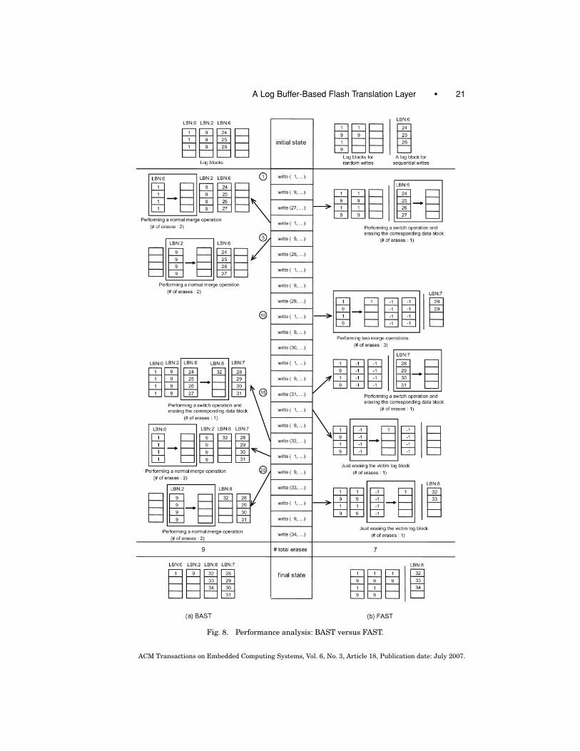
In this section, we compare BAST versus FAST and FAST versus O-FAST usingthe examples in Figures 8 and 9. In the figures, we assume that the number oflog blocks is four and the number of sectors per a block is four. In FAST and O-FAST, one log block is used for sequential writes and the other three log blocksfor random writes. Regarding the victim selection for log block replacement,BAST and (O-)FAST have a little variation in their strategies. In case of BAST,since the victim selection strategy is not clearly mentioned by Kim et al. [2002],we assume the following: (1) if an overwritten sector has its corresponding logblock and the block is full, the log block is selected as victim, (2) if the new sectordoes not have its corresponding log block, we select a log block to which we canapply the switch optimization as victim, if any, and (3) in other case, we select avictim log block in a round-robin fashion. (O-)FAST selects a victim block fromthe RW log blocks in a round-robin way. The write pattern is intended to includeboth small random writes (S1, S9, Figure 8) and large sequential writes (S27,S28, S29, . . . , Figure 8).
In Figure 8, FAST requires seven erase operations to process all the writerequests, while BAST needs nine erase operations. Both FAST and BAST re-quire four merge operations. In BAST, each normal merge operation requirestwo erase operations. In FAST, however, even though the first victim replace-ment requires three erase operations (one for the victim block and two for thedata blocks 1 and 3), two merge operations after the write request result insimple merge operations, which requires just one erase operation.
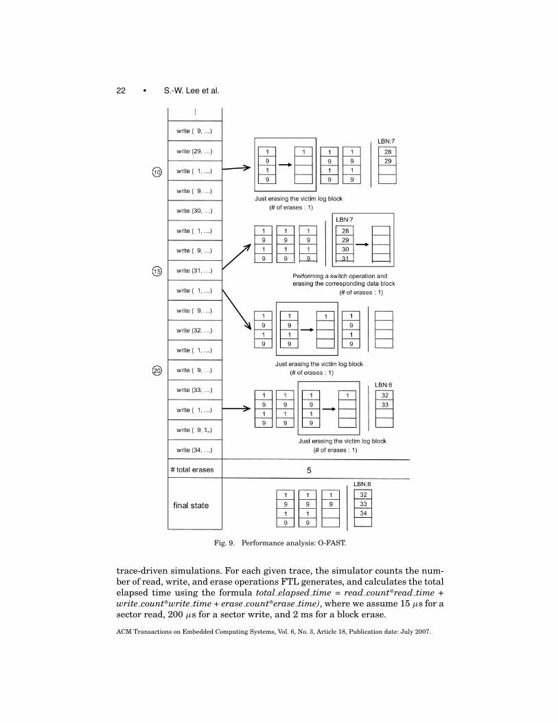
Figure 9 shows how many erase operations O-FAST requires for the samewrite pattern used in Figure 8. Prior to the write request , O-FAST proceedslike FAST in Figure 8. The first merge operation happens at the write request ,where the victim log block is the first block in the RW log blocks. Fortunately,since up-to-date versions of all the sectors in the victim (i.e., S1’s and S9’s)exist in the nonvictim log blocks, we can delay the merge operations for thetwo corresponding blocks and just need to erase only the victim block. Theother merge operations in the figure require only one erase operation. For thisreason, O-FAST incurs five erase operations to process all the write requests,while FAST requires seven erase operations. In summary, the “lazy merge” inO-FAST allows us to skip two erase operations, compared to the “eager merge”in FAST. This is the intrinsic difference between the two schemes.
4. PERFORMANCE EVALUATION
To evaluate and compare the performance characteristics of BAST, FAST,and O-FAST, we developed a simulator for each scheme and performed
ACM Transactions on Embedded Computing Systems, Vol. 6, No. 3, Article 18, Publication date: July 2007.
A Log Buffer-Based Flash Translation Layer • 21
Fig. 8. Performance analysis: BAST versus FAST.
ACM Transactions on Embedded Computing Systems, Vol. 6, No. 3, Article 18, Publication date: July 2007.
22 • S.-W. Lee et al.
Fig. 9. Performance analysis: O-FAST.
trace-driven simulations. For each given trace, the simulator counts the num-ber of read, write, and erase operations FTL generates, and calculates the totalelapsed time using the formula total elapsed time = read count*read time +write count*write time + erase count*erase time), where we assume 15 μs for asector read, 200 μs for a sector write, and 2 ms for a block erase.
ACM Transactions on Embedded Computing Systems, Vol. 6, No. 3, Article 18, Publication date: July 2007.

A Log Buffer-Based Flash Translation Layer • 23
Table I. The Traces Used in Experiments
Pattern Description # of writes
A Workload from digital camera (A company) 2,199,200
B Workload from digital camera (B company) 3,144,800
C Workload from Linux O/S 398,000
D Workload from Symbian O/S 404,900
E Uniform random writes (generated synthetically) 150,000
Table I shows the five traces we used in the experiment: the first four traces(pattern A–D) have been obtained from the authors of BAST [Kim et al. 2002]and the fifth trace (pattern E) contains uniform random writes, which have beensynthetically generated. We believe that these patterns are complex enough toshow the characteristics of the FTL schemes and to compare them. The randompattern E, in fact, is not a typical workload of contemporary flash memoryapplications. Nevertheless, because the flash memory is expected to be usedas the storage media for more general computer systems with more randomwrite patterns, including laptop computers [Lawton 2006; Paulson 2005], it ismeaningful to compare three FTL schemes over a random write pattern.
Figure 10 shows the experimental results of BAST, FAST, and O-FAST us-ing the trace workload, where the total elapsed time is measured in the unitsof a second. If necessary, we will explain the performance difference of FASTand O-FAST in detail. The performance metrics we used are the number of to-tal erase count and the total elapsed time. Compared to read/write operations,the erase operation is more time consuming and, therefore, the efficiency ofan FTL scheme mainly depends on how many erase operations it can avoid.In the experiment, we test the impact of the number of log blocks by increas-ing the number of log blocks from 4 to 64 for each configuration. FAST beatsBAST consistently in all the patterns. Now, we will investigate each case indetail.
First, let us explain the case of pattern E with uniform random writes, inwhich the advantage of FAST/O-FAST is clearly demonstrated. Each write oper-ation in BAST may result in a costly merge operation, since the write operationcan place only in its dedicated log block. Please note that the performance inBAST does not improve with the number of log blocks: because the write pat-tern is very random (that is, the number of hot blocks is generally more than64), the space utilization of the log blocks in BAST does not improve. In con-trast, each write operation in FAST is appended in the end sector of the logblocks and, thus, erase operations can be considerably reduced. In addition,the performance improves with the number of log blocks. The pattern E doesnot include any overwrite sequence for which O-FAST will benefit and, thus,the performance of FAST and O-FAST is identical.
Next, let us examine the pattern A and B, which are generated from digi-tal cameras and thus contain both small random writes and large sequentialwrites. In both patterns, FAST consistently outperforms BAST, especially whenthe number of log blocks is equal to or less than 16. The performance gap inthis range is mainly because of the reduction of erase count in the small ran-dom overwrites. As we mentioned in Section 2, the intelligent switch operation
ACM Transactions on Embedded Computing Systems, Vol. 6, No. 3, Article 18, Publication date: July 2007.

24 • S.-W. Lee et al.
Fig. 10. Performance evaluation: results.
ACM Transactions on Embedded Computing Systems, Vol. 6, No. 3, Article 18, Publication date: July 2007.
A Log Buffer-Based Flash Translation Layer • 25
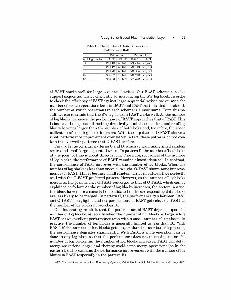
Table II. The Number of Switch Operations:
FAST versus BAST
Pattern A Pattern B
# of log blocks BAST FAST BAST FAST
4 49,213 48,529 79,214 78,472
8 49,212 48,628 78,910 78,734
16 49,278 48,628 78,664 78,720
32 48,757 48,628 78,470 78,770
64 48,083 48,693 77,759 78,794
of BAST works well for large sequential writes. Our FAST scheme can alsosupport sequential writes efficiently by introducing the SW log block. In orderto check the efficiency of FAST against large sequential writes, we counted thenumber of switch operations both in BAST and FAST. As indicated in Table II,the number of switch operations in each scheme is almost same. From this re-sult, we can conclude that the SW log block in FAST works well. As the numberof log blocks increases, the performance of BAST approaches that of FAST. Thisis because the log block thrashing drastically diminishes as the number of logblocks becomes larger than the number of hot blocks and, therefore, the spaceutilization of each log block improves. With these patterns, O-FAST shows asmall performance improvement over FAST. In fact, these patterns do not con-tain the overwrite patterns that O-FAST prefers.
Finally, let us consider patterns C and D, which contain many small randomwrites and small large sequential writes. In pattern D, the number of hot blocksat any point of time is about three or four. Therefore, regardless of the numberof log blocks, the performance of BAST remains almost identical. In contrast,the performance of FAST improves with the number of log blocks. When thenumber of log blocks is less than or equal to eight, O-FAST shows some improve-ment over FAST. This is because small random writes in pattern D go perfectlywell with the O-FAST preferred pattern. However, as the number of log blocksincreases, the performance of FAST converges to that of O-FAST, which can beexplained as follow: As the number of log blocks increases, the sectors in a vic-tim block have more chance to be invalidated so the corresponding data blocksare less likely to be merged. In pattern C, the performance gap between FASTand O-FAST is negligible and the performance of BAST gets closer to FAST asthe number of log blocks approaches 16.
One interesting result is that the performance of BAST depends upon thenumber of log blocks, especially when the number of hot blocks is large, whileFAST shows excellent performance even with a small number of log blocks. Inpractice, the number of log blocks is generally limited to less than 10. WithBAST, if the number of hot blocks gets larger than the number of log blocks,the performance degrades significantly. With FAST, a write operation can bedone in any log block so that the performance does not much depend on thenumber of log blocks. As the number of log blocks increases, FAST can delaymerge operations longer and thereby avoid some merge operations (as in thepattern D). This explains the performance improvement with the number of logblocks in FAST (especially in the pattern E).
ACM Transactions on Embedded Computing Systems, Vol. 6, No. 3, Article 18, Publication date: July 2007.

26 • S.-W. Lee et al.
5. CONCLUSIONS
In this paper, we proposed a novel FTL scheme, FAST, that outperforms thewell-known log block scheme BAST. Its performance advantage mainly comesfrom the full associativity between the logical sectors and log blocks. By ex-ploiting full associativity, FAST can avoid the log block thrashing phenomenon,delay merge operations as late as possible, and skip many unnecessary mergeoperations. These optimizations drastically reduce the number of expensiveerase operations. Another advantage of FAST is that it guarantees a reason-able performance even with small number of log blocks and its performanceimproves gracefully with the number of log blocks. In fact, FAST with only 4 to8 log blocks can provide the same performance as BAST with more than 30 logblocks.
In the future, we will devise some more optimization opportunities from fullassociativity. We will also explore what the theoretical performance optimumfor flash memory is under a given workload. One good starting point is theconcept of “ideal scheme” in Kim et al. [2002], which is defined as “a schemethat performs one erase operation for every n-sector write operation, where nis the number of sectors per block.” Finally, we would like to investigate thechasm between traditional file systems (i.e., Windows’ FAT, Unix’s file system)and Flash’s FTL, and its symptoms, such as file system aging. This work willbe a corner-stone for flash-aware file system.
ACKNOWLEDGMENTS
We wish to thank Dr. Sang-Lyul Min and his FAST research group at SeoulNational University for providing us with the several workloads used in thispaper. We would also like to thank three anonymous reviewers who providedmany useful comments that helped improve the quality of this paper.
REFERENCES
BAN, A. 1995. Flash file system. United States Patent, No. 5,404,485, April.
CHUNG, T. S., PARK, D. J., PARK, S. W., LEE, D. H., LEE, S. W., AND SONG, H. J. 2006. System
software for flash memory: a survey. In Proceedings of the 2006 IFIP International Conferenceon Embedded And Ubiquitous Computing (EUC 2006). (Aug.) Seoul, Korea.
DOUGLIS, F., CACERES, R., KAASHOEK, M. F., LI, K., MARSH, B., AND TAUBER, J. A. 1994. Storage
alternatives for mobile computers. In Proceedings of the 1st Symposium on Operation SystemsDesign and Implementation (OSDI), Monterey, CA, November 1994, J. LEPREAU, Eds. Usenix
Association, Berkeley, CA. 25–37.
ESTAKHRI, P. AND IMAN, B. 1999. Moving sequential sectors within a block of information in a flash
memory mass storage architecture, United States Patent, No. 5,930,815, July.
GAL, E. AND TOLEDO, S. 2005. Algorithms and data structures for flash memories. ACM ComputingSurveys 37, 138–163.
HENNESSY, J. L. AND PATTERSON, D. A. 2003. Computer Architecture: A Quantitative Approach, 3rded. Morgan Kaufmann, San Mateo, CA.
KIM, B. S. AND LEE, G. Y. 2002. Method of driving remapping in flash memory and flash memory
architecture suitable therefore, United States Patent, No. 6,381,176, April.
KIM, J. S., KIM, J. M., NOH, S. H., MIN, S. L., AND CHO, Y. K. 2002. A space-efficient flash translation
layer for compactflash systems. IEEE Transactions on Consumer Electronics 48, 366–375.
LAWTON, G. 2006. Improved flash memory grows in popularity. IEEE Computer 39, 1 (Jan.), 16–
18.
ACM Transactions on Embedded Computing Systems, Vol. 6, No. 3, Article 18, Publication date: July 2007.
A Log Buffer-Based Flash Translation Layer • 27
PAULSON, L. D. 2005. Will hard drivers finally stop shrinking? IEEE Computer 38, 5 (May), 14–16.
SAMSUNG ELECTRONICS. 2005. Nand flash memory & smartmedia data book.
SHINOHARA, T. 1999. Flash memory card with block memory address arrangement. United States
Patent, No. 5,905,993, May.
Received April 2005; revised October 2005 and March 2006; accepted May 2006
ACM Transactions on Embedded Computing Systems, Vol. 6, No. 3, Article 18, Publication date: July 2007.


![UNIVERSITY OF CAMBRIDGE INTERNATIONAL EXAMINATIONS … Levels/Computer Studies (7010)/7010... · USB flash memory [2] (e) Printer buffer ... Complete the flowchart using items from](https://img.pdfslide.us/doc/110x75/5aeaaf907f8b9a45568c1a4d/university-of-cambridge-international-examinations-levelscomputer-studies-70107010usb.jpg)