Embed Size (px)
Citation preview
6"q,r.-I
<©
........_a__- _'ll I_%,DF'I_,_ _ ! a --.,-p..
NATIONAL
;iiiii!iiii!!!!iiiiiii!!iiiiiii!!ii!iii:i!/:
ADVISORY
COPYCOMMITTEE
FOR AERONAUTICS!!!
TECHNICAL M_ORANDUM 1222
i
i
INVESTIGATION OF T_ _DEL ME 210 IN THE SPIN
i,i ii!i::iili:i:!iiii:ii:iiiill:iiii:iii
WIND TUNNEL 0F THE DVL
[
FOURTH PARTIAL REPORT-MODEL WITH LONG FUSEI&GE
AND WITH A VEE TAIL
By A. Huffschmid
Translation of ZWB Untersuchungen und
Mitteilungen Nr_ 1288, June 1944
:[
FILE OOPYW__nApril 1950
i iiii ii rllllrlil i fi i
To be returnedtottte files of the NationalAdvisoryCommittee
for AeronauticsWashington,D. &
https://ntrs.nasa.gov/search.jsp?R=19990054421 2018-08-08T01:03:27+00:00Z
NATIONAL ADVIS0_ COMMITTEE FOR AERONAUTICS
TECHNICAL MEMORANDUM 1222
INVESTIGATION OF THE YODEL ME 210 IN TIWE,SPIN
WIND TUNNEL OF THE DVL
F0_ PAI_IAL REPORT - MODEL WITH LONG FUSELAGE
AND WITH A VEE TALL* **
By A. HuffschnLid
ABSTRACT :
After conclusion of the spin investigation of the
model Me 210 with elongated fuselage and central vertical
tail surfaces (model condition III; reference 3), tests were
performed on the same model with a vee tail (model con-
dition IV). Here the entire tail surfaces consist of only
one surface with pronounced dihedral. Since the blanketing
of the vertical tail surfaces by the horizontal tail sur-
faces, which may occur in case of standard tail surfaces,
does not occur here, one could expect for this type of tail
surface favorable spin characteristics, particularly with
*"Untersuchung des Me 210-Modells im Trudelwindkanal der DVL.
4. Teilbericht. Modell mat langemRumpf und mit V-Leitwerk." Zentrale
ft[r wlssenschaftliches Berichts_esen der Luftfahrtforschung des
Generalluftzeugmeisters (ZWB), Berlin--Adlershof, Untersuchungen und
Mitteilungen Nr. 1288, June 15, 1944.
*_NACA reviewer's note: Data obtained at the Langley Aeronautical
I_boratory indicate that loading may influence the effectiveness of a
vee tail in spin recovery. Inasmuch as the results presented herein
were obtained with a single model at only one loading, they should not
be interpreted as indicating the effects of a vee tail for all designs.
2 NACATM1222
OUTLINE:
respect to rudder effectiveness for spin recovery. However,the test results did not confirm these expectations. Thesteady spin was shownto be very irregular; regardingrudder effectiveness the vee tail surfaces proved to beinferior even to standard tail surfaces; thus they repre-sent the most unfavorable of the four fuselage and tail--surface combinations investigated so far.
I. PURPOSEOFTHETESTS
If. DESCRIPTIONOFTHEMDDEL
IIl. SYMBOLSANDDEFINITIONS
IV. TES_2RESULTS
A. Steady Spin
B. Effect of Control Measuresfor Spin Recovery
V. EVALUATIONOFTHEMODELME210 WITHLONGFUSELAGEANDWITHVEETAlL SURFACES
VI. SWJMMA/_ANDCOMPARISONWITHTHEMDDELCONDITIONSINVESTIGATEDSOFAR
VII. REFERENCES
I. PURPOSEOFTHETESTS
In the systematic spin investigation on a model Me210 the effectof a variation in the form of fuselage and tail surfaces on the spinbehavior is determined. The following model variations have alreadybeen investigated:
Short fuselage and central vertical tall surfaces:model condition I
Short fuselage and twin vertical tall surfaces:model condition II
NACATM 1222 3
Long fuselage and central vertical tail surfaces:model condition llI
The results of these three test series have already been published(references i, 2, and 3)- As a fourth variation, a model with elongatedfuselage and with so-called vee tail surfaces (model condition IV) wasinvestigated in the present test series. In this arrangement of the tailsurfaces, horizontal and vertical tail surfaces were replaced by asurface of 35° dihedral (see fig° 3.) Besides other advantages, as forinstance reduction of the high-speed drag, good rudder effectiveness for
spin recovery was to be expected for this arrangement of the tall surfaces,
since no reduction of the rudder effectiveness due to blanketing of the
air flow by the horizontal tail surfaces could occur as it had been
observed to occur for the central vertical tail surfaces°
IIo _SCRIPTION OF THE MODKL
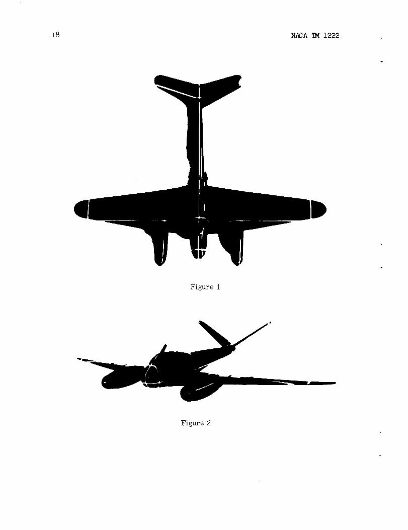
As in the former test series, a geometrically and dynamically
similar model of the scale k = l:16 served as test carrier (see figs. 1
and 2); it is the same model on which the measurements of the previous
test series had been performsd° Details of the _odel are described
in UM 1176; here only a few remarks concerning the vee tall surfaces
will be added°
The tail surfaces consist in this case of only one surface of
35 ° dihedral° Due to this dihedral, moments about the transverse or
vertical axis of the airplane may be produced by corresponding or opposite
deflection of the two control surfaces. The angular range of each
control surface is ±50o° Therein the elevator deflection _ upward
is 30 °, downward 20 ° (for standard tail surfaces ±27o); the rudder
deflection produced by superpositlon amounts to 20 ° on the up-going rudder,
30 ° on the down-golng rudder, so that a maximum rudder deflection
of _ = ±25 ° results (for standard tail surfaces _ = ±35o).
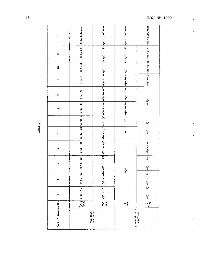
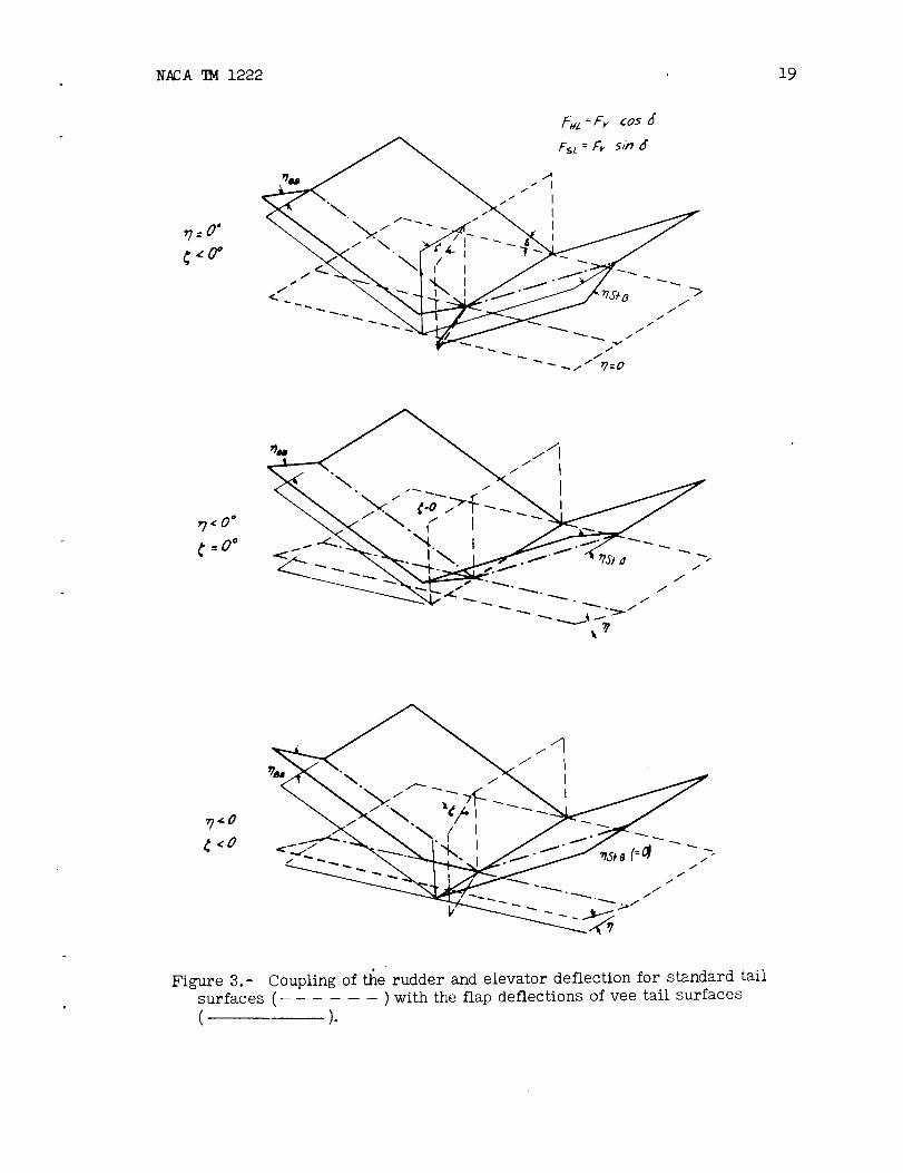
The coupling of the elevator and rudder deflections in the control--
surface deflections for vee tall surfaces is not easily defined (see
fig° 3). Thus the control-surface deflections for vee tail surfaces for
the investigated control measures are divided into the rudder and elevator
deflections for a customary type of tail surfaces in table 1 (see also
section IV). For better visualization, in the discussion of the test
results, the corresponding rudder or elevator deflections for standard
tail surfaces are always given instead of the total control--surface
deflections for vee tail surfaces, in order to make a comparison with
the former model conditions possible. The following symbols signify for
vee tail surfaces: St B, starboard; BB, port side; _ > 0, surface
4 NACATM 1222
depress_do For standard tail surfaces the customary definitions arevalid again: _ > 0 signifies stick pushed forward; _ > 0 signifiesrudder deflected toward the right (trailing edge of the rudder pointingtoward port side is thus spin--promoting in left spins).
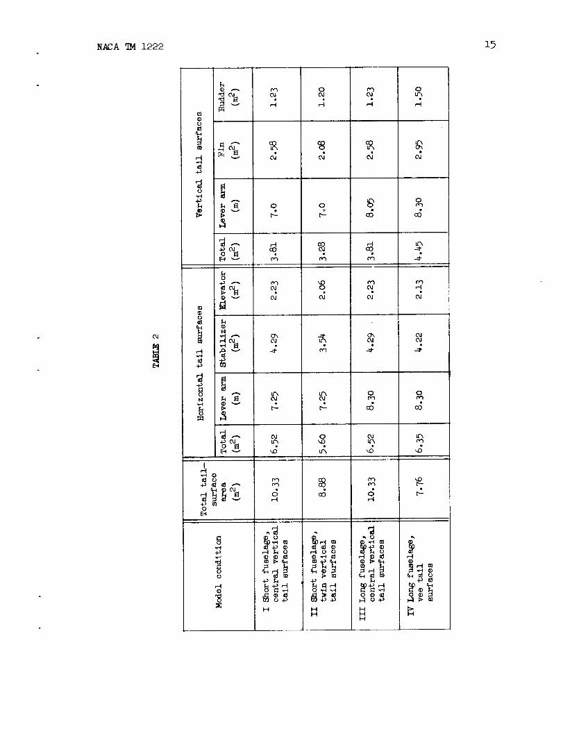
Due to the particular shape of the vee tail surfaces there resultfor a considerably amaller actual total surface of the tail surfaces,projections into the plane of horizontal and vertical tail surfaceswhich are larger than the corresponding surfaces for central verticaltail surfaces. Table 2 gives for comparison the magnitudes of the tail-surface areas and their lever arms (referred to a position of the centerof gravity of 0.20_aer) for the four different model conditions; allquantities refer to full-scale airplanes.
The momentsof inertia were equal to those of model condition III,except for slight deviations; they were:
I x = 4785 kgms2; Iy = 3120 kgms2; I z = 7540 kgms2
The simulated flying weight was again 7540 kilograms. The position ofthe center of gravity was varied in a range of 14--percent to 28-percentof the meanaerodynamic chord. In the tests with extended slats theslat configuration corresponded to the previous design (L_41176, p. 4).
IIio SYMBOLSANDZEFINITIONS
The symbols and definitions are identical with those of the previouspartial reports (reference 3, P. 5.) All model values are again convertedto full--scale values°
IV. TESTRESULTS
A. Steady Spin
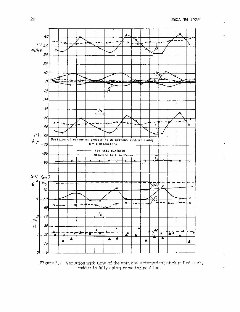
The steady spin condition of the model with vee tail surfacesdiffered considerably from that of the former tail-surface combinations.Whereasfor the latter the spin was very steady, the spin of the modelwith vee tail surfaces showedstriking oscillations; the variation ofthe characteristics with the timo showslarge periodical fluctuationsparticularly of the pitch angle _ and the speed of rotation _; theperiod of oscillation of these superimposeddisturbances is about
NACATM 1222
5 seconds (in the model test 1.25 SeCo). As an example, the variationwith time of the most important spin characteristics is represented infigure 4; the variation of the spin characteristics for the model withcentral vertical tail surfaces and long fuselage for the sametestconditions is plotted for comparison in a dashed line. A correspondingvariation of the rate of drop took place with the continuous rapidvariation of the angle of attack; thereby the test performance was mademore difficult inasmuchas the Jet velocity of the tunnel could not beadapted sufficiently fast to the respective resultant rate of drop ofthe model, so that the model occasionally performed violent movementsinthe direction of the Jet axis. On the other hand the model showednotendency to movefrom the Jet center°
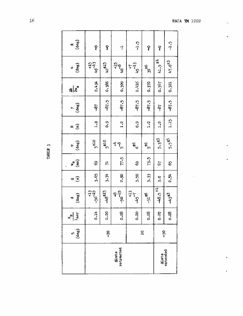
The meanvalues of the spin characteristics (from several tests)are compiled for different positions of elevator and center of gravityand with slats extended and retracted in table 3. For $, _, andthe limits of the fluctuations are indicated° The rudder was in allcases adjusted to a fully spin--promoting position (_ = - 25°). Allvalues apply to a flight altitude of 4 kilometers.
Aside from the irregularity already mentioned the steady spin isslightly different from that of model condition III in other respectsas well; the pitch is, on the average, 5° larger and the speed ofrotation slightly higher than for the model with standard tail surfaces.For the rest, however, the meanvalues of the characteristics remainwithin the limits of the test series performed so far.
For extended slats the spin was very steady; the meanvalues ofthe spin characteristics showthe sametendency found in the test seriesso far according to which the spin flattens and speed of rotation andrate of drop decrease somewhatwhenthe slats are extended. As for theformer model conditions the angle of sideslip and the spin radius werevery small for all tests (with slats retracted and extended.)
Bo Effect of Control Measuresfor Spin Recovery
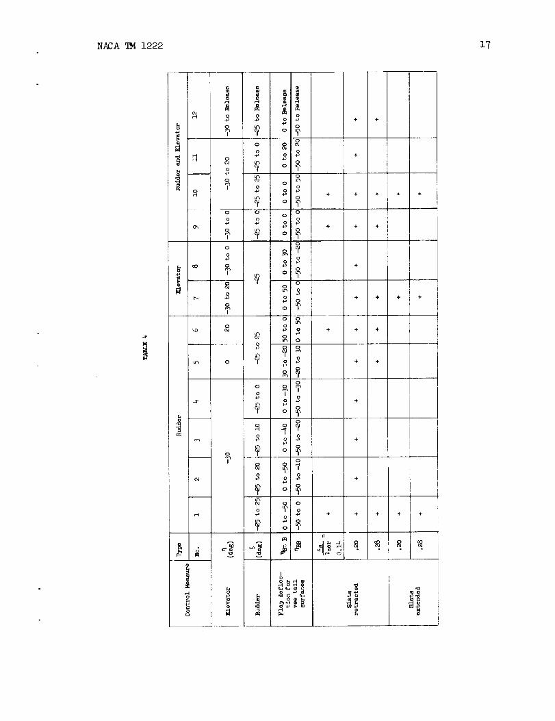
In order to clarify the important problem of control surfaceeffectiveness for vee tail surfaces, a numberof control measures weretaken and the unsteady course of motion after starting of the controlmeasure observed° The program of the measurementscorresponded, onprinciple, to that of the previous test series. It had been extendedonly inasmnchas smaller control deflections against the spin, too, wereinvestigated because it had been found for model condition III thatsmaller rudder deflections are less effective° For the samereason,one of the two control surfaces or both of them simultaneously wereonly movedto neutral position° Table 4 shows a compilation of thetests performed for the different positions of the center of gravity
6 NACATM 1222
(slats retracted and extended) marked by a cross ( + )o All resultsgiven here refer to a flight altitude of 4 kilometers; a few testscorresponding to a flight altitude of 1 kilometer were performed atrandom; results similar to those for 4 kilometers altitude wereobtained. The simulation of an altitude of lO kilometers was notpossible due to the limited air speed of the spin wind tunnel sincethe model for this air density again showedan obvious tendency towardsa steep spin; however, in view of the high surface loading of the modeland the small air density required for such high flight altitudes, asteep spin condition cannot be maintained for any length of time°Because of the tendency toward a steep spin it may, however, safely beassumedthat the spin behavior at high flight altitudes is similar tothat at 4 kilometers altitude.
As in the previous partial report, the test results are representedchiefly on the basis of the variation with time of the pitch anglewhich is the primary characteristic for determining the effectivenessof a control measure° Attainment of a pitch angle of ¢ = - 70° isagain required as criterion for spin recovery. The effects of the variouscontrol measuresare comparedbelow with one another and with the corre-sponding results for the model with standard tail surfaces and longfuselage°
i. Model with slats retracted.
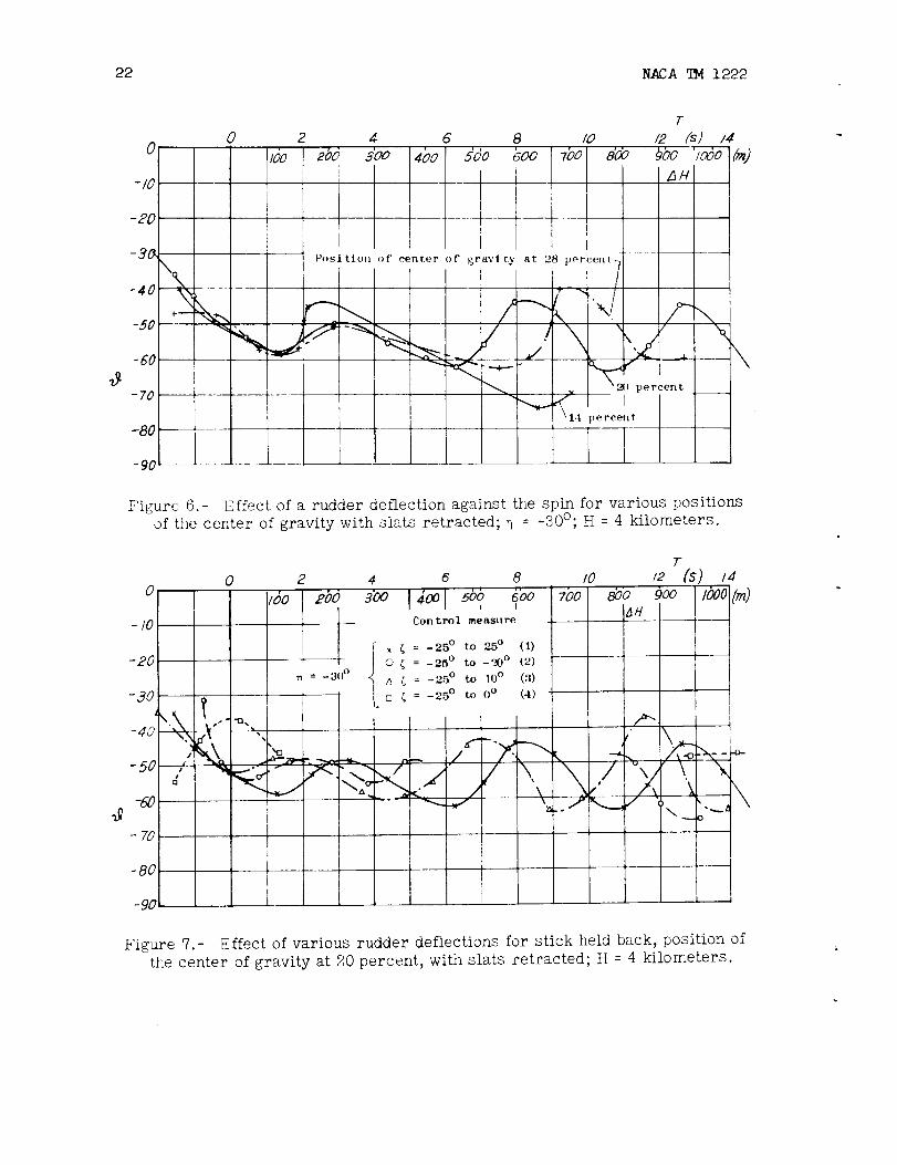
a. Effect of a rudder actuation.
For stick held back, a full rapid rudder deflection against the
spin 1 does not result in recovery for any of the investigated posit_ons
of the center of gravity (see fig. 6); the disturbance oscillation
of ¢ and so forth mentionedbefore, already present in steady spin,
continues _fter introduction of the rudder measure, with the oscillations
continuing with the same amplitude and frequency about an only very
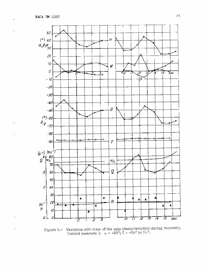
slowly increasing mean value° For a position of the center of gravity
at 20 percent the variation with time of all spin characteristics is
represented in figure 5o Recovery cannot yet be established after
16 seconds, that is, 8 spin turns or 1200-meter loss of altitude; for a
position of the center of gravity at 28 percent conditions are similar,
whereas a somewhat more favorable behavior may be assumed for the fore-
most position of the center of gravity. True to expectation, results
are still more unfavorable for smaller rudder deflections against the spin
iThis rudder measure corresponds approximately to the standard control
measure suggested by R_Shler (DVL) which is: a. full rapid rudder
deflection against the spin; b. no pushing forward of the stick but
yielding if it tends forward by itself; c. aileron in mean position°
NACATM 1222 7
(fig. 7)° Comparingthis result with that of a rudder deflectionagainst the spin for central vertical tail surfaces one finds a pro-nounced deterioration of recovery characteristics for tail surfaces°It has to be noted that the rudder deflection against the spin amounts,for the vee tall surfaces, on the average to only 25° in contrast to35° for standard tall surfaces; however, for the latter one could observe,for a position of the center of gravity at 20 percent even in case of arudder deflection against the spin reduced to 25°, perfect spin recoveryafter lO seconds (see UM1176, fig. 6). It could also be assumedthatin the continuous alternation of flat and steep spln the rudder reversalhappenedto take place always during flat spin and that this was thereason for the delay in recovery. Figure 6 shows, however, that therudder was actuated in all three cases at a pitch angle of _ _ - 50°(that is, in steep spin). Thus it maybe concluded that the effectivenessof a rudder deflection is not as good for vee as for standard tallsurfaces. This falure is the more striking as the oscillatory natureof the steady spin phenomenonpermits one to infer a very slight stabilityof the latter so that even very small tall--surface momentsought to besufficient to disturb it.
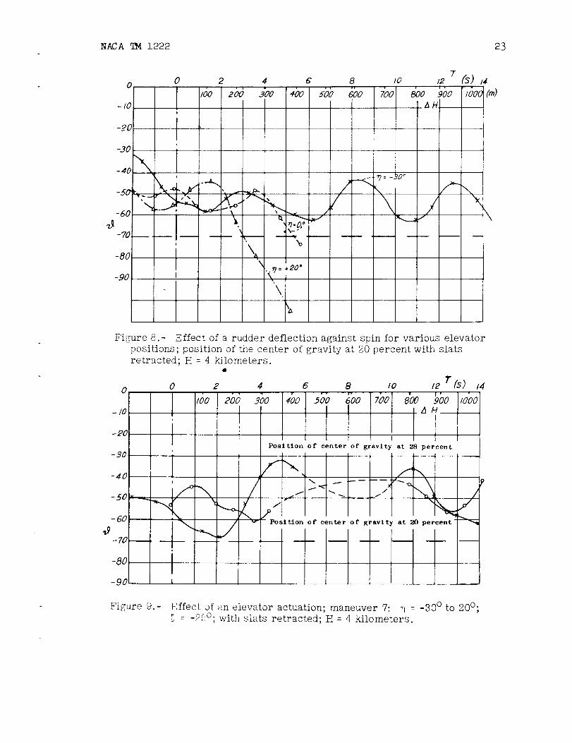
Wlth the stick held In neutral position or pushed forward, recoverytakes place after 5.4 seconds or 3 seconds, respectively (see fig. 8)°These two positions of the stick are, therefore, considerably morefavorable for spin recovery than the position of stick held back. Thesametendency had been established in the previous test series° However,since the elevator, due to the free-stream conditions in spin, alwayswill float up, actuation of the rudder will probably always representthe most important control m_asure in case of stick held back.
Since in the former test series extension of the dive brakes hadproved ineffective, they were not actuated in this test series.
b. Effect of an elevator actuation.
Pushing the stick forward from _ = -- 30° to + 20° proved completelyineffective for the present tail-surface arrangement (fig. 9); the modelcould be observed spinning for an arbitrary length of time after therudder had been actuated; recovery did not take place even after alonger lapse of time° Likewise, of course, moving the elevator to neutralposition proved ineffective. This result is noteworthy inasmuch as forall types of tail surfaces investigated so far pushing forward of thestick had, under all circumstances, brought about a very rapid spinrecovery. Even though the practical value of this control measure forstandard tall surfaces is questionable, due to the large control forces,this observation showsvery clearly the deterioration of the controleffectiveness for vee tall surfaces.
8 NACA_I222
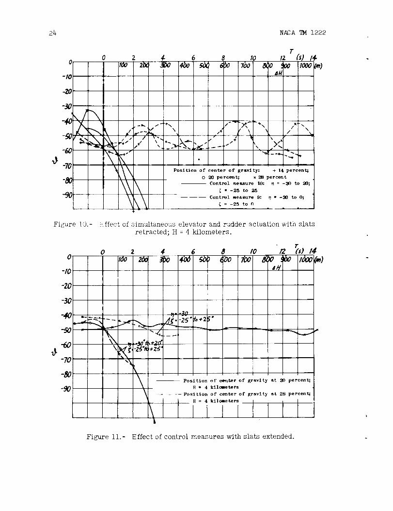
c. Effect of simultaneous actuation of rudder and elevator.
If both control surfaces are fully deflected against the spin(control measure10), spin recovery occurs very rapidly for all positionsof the center of gravity (fig. 10). After not more than 0.8 second to1.5 seconds subcrltical angles of attack are attained; in the end themodel overshoots the vertical (_max= -- ll0°)" The loss in altitude dueto spin recovery amounts for this control measureonly to barelylO0 meters; the airplane performs, approximately, another spin half--turn. In order to examine the practical feasibility of this combinedcontrol measure, a rough calculation of the control forces was performed.A few rough assumptions had to be made (for instance concerning theCw-Values of the control surfaces); however, a comparison of calculationsusing the sameassumptions for the Ar 96 with existing control-forcemeasurementsin spin by HShler shows that the calculation gives thecontrol forces with relatively high accuracy (in the case of the Ar 96,for instance, approx, lO percent). The calculation always used thenormal componentof the resulting velocity vector on the control--surfacearea of the tail surfaces. For a steady spin condition with the followingmeanvalues of the spin characteristics
¢m_ 48°; c_ m = _ = 420; WSm= 72m_s;_ = 3.3/s; _ _ 0°
and for a control surface deflection of _BB= 50°" qStB = 0°' thatis, _ = 30° , _ = 25° resulted in a control-surface momentof about78 kilogram meters; if a transmission ratio in the control linkageof 1.5 and a length of the control stick of 0.5 meter are assumed, thecontrol force is calculated to be about 230 kilograms_ Performance ofthis control measure in practice seemsimpossible, even if the fact istaken into consideration that for vee tail surfaces the pilot's handand foot pressure add up in the control operation.
If both control surfaces are movedonly into neutral position(control measure9), recovery does not take place, regardless of theposition of the center of gravity (fig. 10); thus these results agreewith thosa for standard tail surfaces.
Release of both control surfaces is absolutely ineffective; themodel continues spinning without change for an arbitrary length of time.
2° Model with slats extended.
In the tests with extended slats a pronounced steadying of the spin
was noticeable. The mean values of the decisive spin parameters did not
NACATM 1222 9
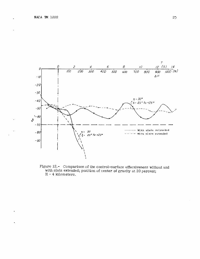
showany particular variation due to the extension of the slats; however,the superimposeddisturbance oscillation of _, _, and so forth mentionedabove had disappeared except for a slight normal amountwhich was observedfor all model configurations in the current test program. With respectto control--surface effectiveness the sameconditions prevailed as in thetests with slats retracted. A rudder deflection against the spin wasabsolutely ineffective for spin recovery whereas simultaneous elevatorand rudder actuation very rapidly brought about recovery. Since therudder deflection against the spin had been ineffective already for themodel with slats retracted, the unfavorable influence of the slatsnoticed in the previous tests does not appear for this model condition.Figure ii showsthe variation with time of _ after starting of thecontrol measures i and i0 for extended slats for positions of the centerof gravity at 20 percent and 28 percent. Figure 12 shows for thevariation with time of _ with slats extended and retracted the positionof the center of gravity at 20 percent.
V. EVALUATIONOFTHEMODELME210 WITHLONGFUSELAGEAND
WITHVEETAlL SURFACES
If the model test results are presupposed to be transferable tothe flight test, the following statements maybe madeconcerning the spincharacteristics of the Me 210 with vee tail surfaces:
For retracted slats the steady spin is characterized by a strikingoscillation; the pitch angle _ and the speed of rotation _ showlarge periodical fluctuations so that the spin condition continuouslyalternates between flat and steep spin (9 = -- 33° to -- 63o); the meancondition maybe called moderately steep (_ = -- 50°). With respect torecovery, a relatively small control effectiveness of the vee tailsurfaces becameevident. Control deflections corresponding to a rudderdeflection against spin for stick pulled back for standard tail surfacesproved to be completely ineffective for all positions of the center ofgravity; for stick held in neutral position or pushed forward recoverytakes place after 5°3 seconds and 3 seconds, respectively. Pushingforward of the stick also was completely ineffective with vee tailsurfaces, in contrast to all previous types of tail surfaces. Only byreversing of both control surfaces (rudder against the spin and simul-taneous pushing forward of the stick) did spin recovery occur rapidlyfor all positions of the center of gravity. Because of the very largecontrol forces, however, this measureprobably has no practical signifi-cance. Movementof both control surfaces merely to neutral position didnot cause spin recovery in any case.
For extended slats a considerable steadying and stabilization of thespin phenomenonoccurs° However, the spin does not becomenoticeably
i0 NACATM1222
flatter by the extension of the slats. With respect to spin recoverya rudder deflection against the spin alone proves ineffective whereasIt brings about a very rapid spin recovery if in connection with simul-taneous pushing forward of the stick.
By installation of vee tall surfaces the spin characteristics ofthe model Me 210, therefore, deteriorated in comparison with the designwith standard tall surfaces. This result Is In agreementwith the solespln investigation of vee tail surfaces knownin foreign literaturewhere the vee tall surfaces also proved inferior to central vertical ta!lsurfaces, the effectiveness of whlch_as reduced by interference (refer--ence 4). In these English tests two vee tail surfaces with 24° and 42odihedral were investigated. In the case of the tall surfaces with 24dihedral, the projection of the tail--surface areas into the plane of thevertical tall surfaces corresponded to the magnitude of the centralvertical tail surfaces referred to for comparison, whereas it was130 percent larger for the model with 45° dihedral. 0nly for these lasttail surfaces, wlth the pronounceddihedral, did spln recovery occur morerapidly than for the model with standard tall surfaces. However, forthe vee tail surfaces of the Me 210 the enlargement of the vertlcal-bail--surface area comparedto that of the central vertical tail surfacesamounts to only about 20 percent; thus according to the English tests,too, an improvement of the spln behavior cannot be expected.
Nodefinite explanation can be given for the failure of the vee tallsurfaces which a priori (because of the absence of interference) would beexpected to lead to favorable spln behavior. The reason probably liesIn the additional yawing and rolling momentsdue to side slip causedby the pronounced dihedral of the tail surfaces; however, their effectcannot be determined in detail° Due to the great number of parametersand especially due to the lack of aerodynamic data (In spln one hasmostly to deal with separated flow) these influences cannot be calculated.
VIo SUMMARYA_DCOMPARISONWITHTHEMODEL
CONDITIONSINVESTIGATEDSOFAR
(See also reference 3, Po 14o)
A model wlth elongated fuselage and with vee tail surfaces wasinvestigated as the fourth fuselage and tail--surface combination in thesystematic investigation of the model Me 210 (model condition IV)oFollowing, the results are briefly summarizedand, with respect to themost essential points, comparedwith those of the previous test sorles(see figo 13). All data are valid for 4 kilometers flight altitude andalways are full--scale values.
NACATM 1222 Ii
i. The spin was for the model conditions I to III moderately steepand characterized by steadiness. The angle of attack was, with slightdeviations, 40° to 45o; the speed of rotation was 0.5 turns per second;the rate of drop was 70 to 80 meters per second. It is true that aboutthe samemeanvalues appeared for model condition IV; however, a strongdisturbance oscillation was superimposed on the main motion so that theangle of attack was subjected to fluctuations of ±15° and that speed ofrotation and rate of drop varied accordingly.
For model condition I the spin at high flight altitudes becameveryflat (_ _ 65°); for the model conditions II to IV a spin similarly steepas at 4 kilometers altitude is to be expected.
Extending of the slats increased the angle of attack by about 6°to l0 ° for model conditions I to III, but did not have any furthersignificant influence. For model conditLon IV the spin with extendedslats becamevery steady and uniform; a variation of the meanvalues ofthe spin characteristics did not occur°
2o The investigated four models showedvery different behavior withrespect to control-surface effectiveness. For the model with slatsretracted, for the model conditions I and IIl, a rudder deflection againstthe spin with stick held back resulted in recovery after about 500 meters
. loss of altitude whereas for model condition II recovery occurred withabout half this loss of altitude. For the model with vee tall surfacesthe samerecovery measure does not cause spin recovery at all. Inde-pendently of the form of the tail surfaces spin recovery takes placefaster for stick in neutral position or pushed forward than for stickheld back.
Pushing forward of the stick with rudder fixed in pro--spin positionalways led to very rapid recovery for model conditions I to III, butfailed completely for the vee tall surfaces (IV).
By simultaneous actuation of rudder and elevator, spin recoveryoccurs for all four model conditions investigated after less than onehalf turn.
If one of the two control surfaces or both simultaneously aremovedmerely to neutral position, recovery does not take place in anycase.
3. For extended slats all control measures failed for model
condition I. For model conditLon II a rudder deflection against spin
caused spin recovery after 6 seconds, for model condition III only after
about 15 seconds; for model condition IV, however, this control measure
failed completely. Rudder deflection against the spin with simultaneous
12 NACATM1222
pushing forward of the stick led to spin recovery in about the samBtime - approximately 2 seconds- for the model conditions II to IV.Due to the large control forces required for this control measure,however, it would probably have no practical value.
With respect to control-surface effectiveness for spin recovery,the following sequencemaybe set up for the investigated fuselageand tail--surface combinations:
1. Model with short fuselage and twin vertical tail surfaces(most favorable case)
2. Model with long fuselage and central vertical tail surfaces
3. Model with short fuselage and central vertical tail surfaces
4. Model with long fuselage and vee tall surfaces (.mostunfavorablecase)
Thus the expectations of improving the spin characteristics'byuse of vee tall surfaces were not fulfilled in any way. The reasonfor the failure of the dihedral tail surfaces probably lies in theyawing and rolling momentsdue to side slip which appear in spin.
For further fuselage and tail-surface combinations the followingmodel conditions are being prepared in the systematic spin investigationof the model Me 910:
Long fuselage and central vertical tail surfaces with horizontaltall surfaces movedto a high position: model condition V
Long fuselage and central vertical tail surfaces, with horizontaltail surfaces movedtoward the front: model condition VI
These tail units for which the arrangement of the tail-surfaceareas was chosen particularly with respect to minimuminterference inspin, and also the use of twin vertical tail surfaces in combinationwith the long fuselage seemto promise good spin characteristics.
TrauslatedbyMary L. MahlerNational Advisory Committeefor Aeronautics
NACATM 1222 13
VII. REFERENCES
i. Untersuchung des Me210-Modells im Trudelwindkanal der DVL.1. Teilbericht: Modell mit K_rzemR;zmpfmudzentralem Leitwerk.Industrieberient J 800/4.
2. Untersuchung des Me210-Modells im Trudelwindkanal der DVL.2. Teilbericht: Mode!l _it KurzemR_nnpf,ind Doppellseltenleitwerk°Industrleberlcht J 800/4.2.
3. Untersuchung des Me 210-Modells imTrudelwlndkanal der DVL°3. Teilberlcht: Modell mat langem Rumpfund zentralemSeltenleltwerk° UM1176.
4. The Vee--Tall in Spin. Aircraft Engeneering 1936, p° 302. (Stephens).
14 NACA _4 1222
O
O%
cO
oo
O
0
o.p
0
o
0
0
0
0-p
o0
?o0
0
_ro
4-)
o
0
o4_
0
0
o4_
0
_m
a
0
0
0
0
0
0
?0
04-)
0
0
04_
0
0
0
0
oo0
0
?o
0
0
04_
o
0
o4J
0
0
04J
v
,-4
oo0
7
0
?0
04_
0
3"0
o
0
3"
0
0
?
80
0
3"
v
,.-I
o
t_
o
0
o4_
I
0
0
0-o
0,.-I
o4_
u%
0C_
o+_
o
v
NACA qM 1222 15
('4
© ,--.
v
r_ ooJ oJ
o
h _ S o o
,-4
0 • •
_ v
o
-0
O
o
r_
0J
cO
_0
O
O
h'h
O_ 0 O_l ,--'1
OJ O_ OJ O_
_0
C_(U
0
O_
o_o_
,3
O _) _
HHH
HH
+_
0J
O
h'A
kO
16 NACA _M 1222
£','t,
v f' ?
-4"t_-.I"
O
et%
v
#-
e,%
v
O O%
_t
8-_0
v
OJ
,4
A
O O
#.-
utA
b-t--
v
C_'4:)
t_
AtO(D
v
Lr_,,4:)
O O
A
v
O
T
m_
,-t
6
f¢3
._T",-:l kO I/_ 0+|
_D 0 t_ r-Ib--
o 6 6 6
0
...1-
_- _ _.
o co oOd OJ £U
6 6
O O
7
m_
a_
NACA _ 1222 17
©
18 NACA [I}41222
Figure i
Figure 2
NACA JIM 1222 19
Figure 3.- Coupling of _e rudder and elevator deflection for standard tail
surfaces ( ) with the flap deflections of vee tail surfaces
( ).
20 NACA TM 1222
(") 40
30
20
•".If_A
-50J
(°) - SO
#.r -7o
-80
-90
)_"_ ' _'W..
Posl tlon
/s
of center of gravity at 20 percent without slats I
H = 4 kilometers
Vee tail surfaces
Standard tail surfaces -- _!
(_-,)4,
3
R
:,.,-,)
/$
O.
Figure _.- Variation with tlme of the spin cha='acteristics; stick pulled back,
rudder in fully spin-promotin_ position.
NACA JIM 1222 2]
5o A
(°)40 . c_ \ -.
20 A --"_
- I0
-20
-30
-4O
(°) _
_.r -zo
""" El'-" ¢ ' /"'\
('2,_l)4
_2
3\
x_
r
_X
W's //i
/
/
.2
R
0
• • &
Rii •
L,&
0 I 2 9 i0 II 12 19 14 /5 sec
Figure 5.- Variation with time of the spin characteristics during recovery.
Control measure i: 9 = -30°; _ = -2b ° to 25 °.
22 NACA [[}41222
4
-20
r
0 2 _ 6 8 /0 /2 fs) /_0 ioo 2bo doo 4'o0 j9o _oo -_bo 8_o _bo '/o_o fro)
I i AHI
II
Position of center o(" zravlty at 28 percent
I +--,
_t .,, ,Z+
- 70 _ p . rcen t
4 percent
-80 I-90
\X
Figure 6.- Effect of a rudder deflection against the spin for various positions
of tilecenter of gravity with slats retracted; _ : -30°; H : 4 kilometers.
0 2 4 6 8
0 ',_o 2bO 3i_ ,7oo] 5bb, 6bo,
-IO l Control measure
t x _ = -25 ° to 25 ° (1)
-20 0 _ =-25 ° to _o2)o (2)_? =-3(i° ,5 { =-25 ° to 10 ° (3)
-30 _ _ = -25 ° to 0° (4)
-,o "..k, _.- _..
\'_ i_<_ "" >2 (
_. <_ 1-68 -- -w/
-767
T
Io _n {s) i4zbo _o 9oo iooo{m)
,,.<,-..
'\
_o "''- l
-8o lI
-90
Figure 7.- Effect of various rudder deflections for stick held back, position of
the center of gravity at 20 percent, with slats retracted; H = 4 kilometers.
NACA _I 1222 23
o
- I0
-30
-4O "_
%--
-60
-80
-9O
0
iI
:.I_II
2
t
\\
4
goo +boI
._= +20"
\
TG 8 Jo /2 (s) /_
5bb _o ioo _o 'gbo /_oo _),. i _HI
_7 : -_0 °
z-\/
Figure 8 .-
0
-/0
-20
-30
-40
-St)
-60
,3
-80
-9&
Effect of a rudder deflection against spin for various elevator
positions; position of the center of gravity at 20 percent with slats
retracted; E : 4 kilometers.
0
IIJi
]\__
Position of center of gravity at 28 percent
" i><Position of center of gravity at 20 p <
Figure 9.- Effect of an elevator actuation; maneuver 7: _ : -30 ° to 200;
: -2'_°; with slats retracted; H = 4 kilometers.
24 NACATM1222
o 2 ¢ 6 8
[
TIo 12 /4.
7bo _o oo Iooo
.jJ
-7o
\\
x_ ,,,
\
, .><"'._[__,... ---. _ ,,,.
I
Position of center of gravity: ÷ 14 percent4
0 20 percent; x 28 percent
Control measure 10:
= -25 to 25
Control measure 9:
= -25 to n
_ = -30 to 20;
_7 = -30 to O;
Figure 10.- Effect of simultaneous elevator and rudder actuation with slats
retracted; H = 4 kilometers.
! !
at 20 percent4
at 28 percent;
flFigure 11.- Effect of control measures with slats extended.
NADA _ 1222 25
o
-20
-30
-40
-.40
"-60
- 70
-BO
-90
7
0 2 4 6 8 zo /2 (s) 14
I /do 2bo soo 4o0 5o0 600 700 ooo 9o0 /ooo (_)z_Ft
Figure 12.- Comparison of the control-surface effectiveness without and
with slats extended; position of center of gravity at 20 percent;H -- 4 kilometers.
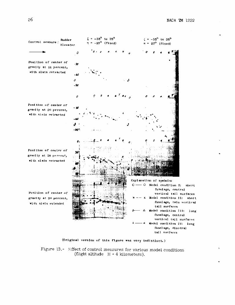
26 NACA _I 1222
Control measure :Rudder
Elevator
0
= -35 ° to 35 °
n = -27 ° (fixed)
'Oa a 4 6
Position of center of
gravity at 14 percent,
with slats retracted-60
J
-90
L
Position of center of
gravity at 20 percent,
with slats retracted
80
J
0 o 2 4 G TS_: o
-30 .
• 4 • _'3
J..Sot. ._
J
T
f__ 2 • 6 sQ, o
= -35 ° to 35 °
= 27 ° (fixed)
o 2 4 6 1P
b
"L1
o z!
Position of center of _[
gravity at 2B percent_ } --
with slats retracted
Position of center of
gravlty at 20 percent_
wlth slats extended
Explanation of symbols:
0 0 Model condition It short
fusel age, central
vertical tall surfaces
Model condition If: short
Puselage, twin vertical
tall surfaces
Model condition III: long
fuselage, central
vertica] tall surfaces
Model condition IV: long
fuselage, dlhedrad
tall surfaces
(Original version of this figure was very Indlstinct.)
Figure 13.- Effect of control measures for various model conditions
(flightaltitude H = 4 kilometers).
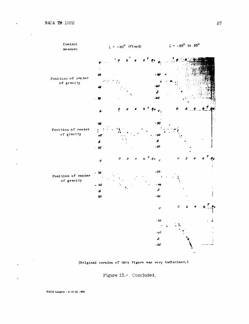
NADA _ 122227
Position oF center
o F gravl ty
= -35 ° (fixed)
'0 ,f 40 ....
\
0 a" 4
8
J
..0O
O T O. S OT
=-35 ° to 35 °
Position of center
of gravity
_O
A
9O
0 Z _ 6
-L_O
J
-9o
0
_o
,I
o 2 4T
g_f
Position of center
of gravity
90
-._0
!
0
-90
t4
\
I
T
0 0 z 4. . _...... _S/
-9o \
(Original version of this figure was very indistinct.)
Figure 13.- Concluded•
NACA-Langley - 4-13-50 - 850