Embed Size (px)
Citation preview
MASTER’S THESIS
2007:063 CIV
JOHAN PILHAGEN
A Literature Review of theStainless Steel 21-6-9 and its
Potential for Sandwich Nozzles
MASTER OF SCIENCE PROGRAMMESpace Engineering
Luleå University of TechnologyDepartment of Applied Physics and Mechanical Engineering
Division of Engineering Materials
2007:063 CIV • ISSN: 1402 - 1617 • ISRN: LTU - EX - - 07/63 - - SE

ABSTRACT
Volvo Aero Corporation has developed a laser welding technique for sandwich nozzles which will have advantages in high repeatability, only commercially available material used and flexibility over other alternative space rocket nozzle manufacturing methods. This master thesis is about the nitrogen strengthened high manganese stainless steel 21-6-9 (a.k.a. Nitronic 40) and its suitability as the main material for a sandwich nozzle and/or its parts (e.g. manifold and stiffeners).
A literature review over the alloys physical, mechanical and process properties was performed and an experimental investigation of weld properties regarding laser welded tensile test, x-ray diffraction measurement on the retain δ-ferrite content and nitrogen diffusion during TIG welding was also performed. The conclusions from this master thesis are that the alloy 21-6-9 seems to fulfil most of the properties for a sandwich nozzle, but the retained δ-ferrite in welds and especially the ability of the metastable austenite to undergo strain and stress-induced martensite transformation at low temperatures could be described as potential “show stoppers” and must be further investigated.
Feasibility tests are proposed for an evaluation of the possible δ-ferrite and martensite problems:
• Cryogenic fracture toughness measurements on 21-6-9 welds.
• LCF measurements with hydrogen environment or at cryogenic temperature for welded and unwelded samples.
• Examine if martensite transformation can occur in sandwich nozzles made of 21-6-9.
• Examine the impact of martensite on LCF and fracture toughness properties in hydrogen environment and at cryogenic temperature.
Other proposed and important tests:
• Evaluate the risk of solidification cracking under high degree of restraint.
• Evaluate a heat-treatment procedures for minimum grain growth when stress-relieving and for possible δ-ferrite reduction
Volvo Aero har utvecklat en lasersvetsteknik för sandwich munstycken vilket kommer att ha fördelar i hög repeterbarhet, endast kommersiella material använt och hög flexibilitet över alternativa tillverkningsmetoder för rymdraket munstycken. Detta examensarbete handlar om det kväve härdade och hög manganlegerade rostfria stålet 21-6-9 (också känt som Nitronic 40) och dess användbarhet som grundmaterial för ett sandwich munstycke och/eller dess delar (t.ex. manifolder och förstyvningar).
En litteratursammanställning över legeringens fysiska-, mekaniska- och processegenskaper har utförts samt en experimentell undersökning på svetsegenskaper angående dragprov på lasersvets, röntgendiffraktions mätningar på δ-ferrit och kväve diffusionsmätningar på TIG svets har också utförts. Slutsatserna från detta examensarbete är att 21-6-9 legeringen uppfyller de flesta egenskaperna för ett sandwich munstycke men uppkomsten av δ-ferrit i svetsarna och möjligheten för den metastabila austenitiska fasen att genomgå töjning- och spänningsinducerad martensit transformation vid låga temperaturer kan beskrivas som potentiella ”show stoppers” och borde undersökas ytterligare.
Tillämpningstest är föreslagna för en utvärdering av de möjliga δ-ferrit och martensit problemen:
• Kryogenisk brottseghetsmätningar på 21-6-9 svets.
• LCF mätningar i vätgas och/eller vid kryogenisk temperatur för svetsade och osvetsade provbitar.
• Undersök om martensit transformation kan ske i sandwich munstycken gjorda av 21-6-9.
• Undersök påverkan av martensit på LCF samt brottseghet i vätgas samt vid kryogenisk temperatur.
Andra föreslagna och viktiga undersökningar:
• Undersök risken för stelningssprickning under svetsning med stora spänningar.
• Ta fram en värmebehandling som ger minimal korntillväxt vid avspänningsglödgning och för möjlig δ-ferrit minskning.

ACKNOWLEDGEMENT
This publication was the final part of a Master degree in Space Engineering, Specialized in Material Science at Luleå University of Technology and has been performed at the Materials Technology department at Volvo Aero Corporation in Trollhättan during September 2006 to February 2007. First I would like to thank my supervisor Frank Skystedt at the materials technology department at Volvo Aero in Trollhättan for the valuable assistant and giving me the opportunity to write my master thesis on a subject that incorporates both material and space engineering.
I would like to thank:
Johan Ockborn for your valuable assistance during my time at Volvo Aero.
Professor Magnus Oden at Luleå University of Technology for being my academical supervisor.
The following people at Volvo Aero Corporation for your kindly help and making the experiments and use of equipment possible: Eleonore Karlsson, Peter Fridolf, Fredrik Lindström, Lars Larsson and Torbjörn Englesson.
Special thanks to:
Mirsattar Hejazifar at Volvo Powertrain, for your expertise and x-ray diffraction measurements on the retained δ-ferrite.
Dr. Alec Mitchell, professor emeritus at University of British Columbia, for spending your time to help me with the nitrogen diffusion.
Professor Lars-Erik Lindegren and doctoral candidate Peter Hedström at Luleå University of Technology for the much appreciated help with the martensite transformation.
Conny Andersson, for your “no problem” attitude and welding expertise when helping out with the liquid copper experiment.
At last, but not at least, all the people at the material technology department for your friendly and welcoming atmosphere during my time at Volvo Aero.
Trollhättan, February 2007
Johan Pilhagen
2

LIST OF CONTENTS
1 Introduction ________________________________________________________________ 5 1.1 General Space rocket nozzle issues and the Sandwich nozzle design________________________ 5
2 Requirements _______________________________________________________________ 7
3 Literature review ____________________________________________________________ 8 3.1 Introduction ____________________________________________________________________ 8 3.2 Material and process properties_____________________________________________________ 8
3.2.1 Temperature capability _________________________________________________________________ 8 3.2.1.1 δ-ferrite_________________________________________________________________________ 8 3.2.1.2 Sigma phase ____________________________________________________________________ 12 3.2.1.3 Carbide sensitization _____________________________________________________________ 14 3.2.1.4 Martensite______________________________________________________________________ 14
3.2.2 Hydrogen embrittlement _______________________________________________________________ 16 3.2.2.1 Theory of HEE and IHE ___________________________________________________________ 17 3.2.2.2 Influence of high SFE elements and manufacturing methods on the hydrogen embrittlement of 21-6-9______ 17 3.2.2.3 21-6-9 hydrogen embrittlement data _________________________________________________ 18 3.2.2.4 Effect by hydrogen on creep, LCF, HCF and fracture mechanics ___________________________ 26
3.2.2.4.1 Creep_______________________________________________________________________ 26 3.2.2.4.2 LCF and HCF ________________________________________________________________ 26 3.2.2.4.3 Fracture mechanics ____________________________________________________________ 27
3.2.3 Formability _________________________________________________________________________ 27 3.2.4 Machinability _______________________________________________________________________ 27 3.2.5 Welding properties ___________________________________________________________________ 27 3.2.6 Heat treatment _______________________________________________________________________ 28 3.2.7 Hot workability and grain size __________________________________________________________ 28 3.2.8 Interface consideration ________________________________________________________________ 29 3.2.9 Elevated temperature use ______________________________________________________________ 31
3.3 Availability, cost and range of uses for 21-6-9 ________________________________________ 32 3.3.1 Availability _________________________________________________________________________ 32 3.3.2 Cost _______________________________________________________________________________ 32 3.3.3 Range of uses _______________________________________________________________________ 33
4 Experiments _______________________________________________________________ 34 4.1 Liquid Copper embrittlement _____________________________________________________ 34
4.1.1 Purpose ____________________________________________________________________________ 34 4.1.2 Procedure __________________________________________________________________________ 34 4.1.3 Results_____________________________________________________________________________ 35 4.1.4 Summary of the liquid copper embrittlement test ____________________________________________ 37
4.2 Tensile test____________________________________________________________________ 38 4.2.1 Performance ________________________________________________________________________ 38 4.2.2 Results_____________________________________________________________________________ 38 4.2.3 Summary of the tensile testing __________________________________________________________ 40
4.3 Examination of weld properties for TIG and laser weld _________________________________ 41 4.3.1 Procedure __________________________________________________________________________ 41 4.3.2 Results_____________________________________________________________________________ 42 4.3.3 Summary ___________________________________________________________________________ 43
5 Discussion _________________________________________________________________ 44
6 Material evaluation matrix ___________________________________________________ 47
7 Conclusions________________________________________________________________ 49
8 Proposals for further work ___________________________________________________ 50
9 Abbrevations ______________________________________________________________ 51
10 References _______________________________________________________________ 52
11 Physical and mechanical properties __________________________________________ 57 11.1 Physical properties _____________________________________________________________ 57
11.1.1 Density and melting range ___________________________________________________________ 57 11.1.2 Dynamic Youngs modulus ___________________________________________________________ 57
3
11.1.3 Poisson’s ratio_____________________________________________________________________ 58 11.1.4 Thermal Expansion_________________________________________________________________ 58 11.1.5 Thermal Conductivity _______________________________________________________________ 59
11.2 Mechanical Properties ___________________________________________________________ 60 11.2.1 Tensile Strength ___________________________________________________________________ 60 11.2.2 Yield Strength_____________________________________________________________________ 60 11.2.3 Elongation________________________________________________________________________ 61 11.2.4 Reduction of area __________________________________________________________________ 61 11.2.5 Creep properties ___________________________________________________________________ 62 11.2.6 Low cycle fatigue properties__________________________________________________________ 63 11.2.7 High cycle fatigue properties _________________________________________________________ 64 11.2.8 Crack propagation properties _________________________________________________________ 65 11.2.9 Fracture toughness _________________________________________________________________ 66
11.3 Mechanical properties of Welded Material ___________________________________________ 67 11.3.1 Yield and tensile strength of welds_____________________________________________________ 67 11.3.2 Elongation of 21-6-9 welds___________________________________________________________ 69 11.3.3 Impact toughness of welds ___________________________________________________________ 70 11.3.4 Fracture toughness of welds __________________________________________________________ 70
12 Appendices ______________________________________________________________ 71 12.1 Appendix A ___________________________________________________________________ 71
4

5
1 INTRODUCTION
Volvo Aero is developing a sandwich nozzle within V2+ Demo. The nickel-base superalloy Haynes 230 was selected for the inner wall. One important selection criteria was the relatively high maximum temperature, approximately 1173 K. The channels used today in Ariane are made of Alloy 600. The material is exposed to hydrogen gas at approximately 5 MPa. Good resistance to higher pressures but lower temperature capability is required for other nozzle applications.
Volvo Aero has identified the austenitic stainless steel 21-6-9 for potential future applications. The purpose of this thesis work is mainly to study the literature for this alloy, especially regarding the resistance to hydrogen embrittlement, physical and mechanical properties and the manufacturability and compare to the material and process selection for the V2+ Demo inner wall.
The critical issues for this alloy shall be determined based on the relationship between the structure, manufacturing processes and mechanical properties. This requires a synthesis and a critical analysis of the available literature. It is also required to propose suitable critical experiments.
1.1 GENERAL SPACE ROCKET NOZZLE ISSUES AND THE SANDWICH NOZZLE DESIGN
The basic principle of the rocket engine is to combust solid, liquid or gaseous propellant containing fuel (e.g. hydrogen) and an oxidizer (e.g. oxygen) in a combustion chamber at high pressure. The hot gas can then only escape through a narrow hole (the “throat”) into a high expansion nozzle. This causes dramatic acceleration of the gas and thus converting thermal energy into kinetic energy. The amount of thrust produced by the rocket engine depends on the mass flow though the nozzle, the exit velocity of the exhaust gas and the pressure at the nozzle exit. The nozzle controls all of these variables, so the nozzle design is of great importance. Loosely speaking, by increasing the chamber temperature and the pressure ratio between the chamber pressure and exit pressure a higher thrust can be achieved, but the chamber and nozzle specifications becomes more demanding with increasing temperature and pressure. The shape of the nozzle is also of importance and the most common is the bell shaped nozzle. The bell shaped nozzle offers a higher area expansion on a shorter length and a more axial gas flow which has less loss of trust than the simplest nozzle shape, the cone. The nozzle is most efficient when the exit pressure equals the ambient pressure which means that the nozzle is most efficient at a specific altitude. More advanced nozzle types have expandable nozzles to counter this and there is research on altitude compensating nozzles (e.g. aerospike).
The nozzle material can not survive the heat from the combustion (~1900 K to 3500 K in a liquid-fueled rocket engine) and therefore must be cooled. Various methods alone or together can be use to cool the nozzle:
• Radiative cooling: Simple structure but very high material temperatures in the order of 1400 K to 2000 K • Ablative cooling: Material attached on the inside of the nozzle which uses the heat to endothermic lower
the nozzle temperature. This method can increase the nozzle weight by considerable amounts. • Film cooling: Gas from the turbines is lead into the nozzle to create a “low” temperature film on the
inside of the nozzle. High material temperatures in the order of 1300 K to 2000 K. • Dump cooling: Small amounts of the low temperature liquid propellant are lead through cooling
channels inside the nozzle. Material temperatures in the order of 1100 K and channel pressure in the order of 5 MPa.
• Regenerative Cooling: Large amounts (20-100%) of the low temperature liquid propellant are lead through the nozzle before entering the combustion chamber. Gives moderate material temperatures in the order of 500K to 800 K but high channel pressures in the order of 20 MPa to 40 MPa.
The nozzle must manage high vibration loads, very fast transition times from zero load to maximum load (~1s), very large temperature gradients over a very short distance and hydrogen environment when liquid hydrogen is used. At the same time the nozzle should have low weight and short life with high reliability. The manufacturing challenge for space rocket nozzles is to produce the very large and thin walled structure that a nozzle consists of. If cooling channels are to be used further difficulties arises when manufacturing the high amount of small cooling channels (in the order of 1000 tubes or milled channels) with enough quality and accuracy needed. For over fifty years the material used for space rocket nozzles and combustion chambers have been various stainless steels, nickel-based super alloys and copper alloys. These alloys have been chosen

for their high strength and high thermal conductivity but due to their high density the results have been heavy engines. There is an ongoing research to replace these high density metal alloys in liquid-fueled rocket engines with light weight composites, but it will probably take at least a decade before the metal alloys are being replaced. Composite materials have been used in nozzles for booster rockets and cruise missiles.
The sandwich nozzle developed at Volvo Aero is designed to be a regenerative cooled nozzle and the manufacturing procedure can be seen in figure 1:1 and the cross-section of the nozzle in figure 1:2. Instead of laser-cut sheets the cones can also be made from example spin-forming.
Figure 1:1. Schematic presentation of the manufacturing procedure for the sandwich nozzle [68]
Several cones can also be welded after each other to form longer nozzles if desired. The material chosen for the nozzle most also be compatible with different welding techniques (e.g. EB and TIG) for attaching e.g. stiffeners and manifolds made of other materials if so chosen. Metal deposit methods are not treated in this report.
The laser welded sandwich technique has been developed at Volvo Aero and some of the advantages this method offer are robust manufacturing process with a high repeatability, commercially available material and flexible costumers demands in choice of material and stiffeners/manifolds assembly [68]. The Russian space industry has successfully used the sandwich nozzle for many years but used brazing instead of welding. Both brazing and welding have advantages over each other, but in this case the brazing was probably ruled out due to high investment cost (e.g. furnaces) and the need to increase the competence for brazing such large structures with proper quality.
Figure 1:2. Cross-section of a sandwich nozzle, the dark regions is welded areas.[68]
6

2 REQUIREMENTS
Requirements based on a temperature range from 20-8201 K.
• Comparable strength with Inconel 600 and Haynes 230.
• Comparable ductility with Inconel 600 and Haynes 230.
• Metallurgic stability in the temperature range.
• Low sensitivity to hydrogen embrittlement for base material and welds in the temperature range.
• Shall be possible to repair.
• Not sensitive to copper contamination.
• Good welding properties.
• No heat treatment needed after welding.
• Good thermo-mechanical fatigue properties in the temperature range. This includes good isothermal Low Cycle Fatigue (LCF) properties with and without dwell time and fatigue loading where both the mechanical and thermal loading changes with time.
• Good High Cycle Fatigue (HCF) properties.
• Good Fracture Toughness (FT).
• Good Crack Growth Rate (CGR) threshold properties.
• CGR properties in the linear elastic and inelastic fracture mechanics regime.
• Good resistance to creep in the temperature range.
• Comparable thermal expansion with Inconel 600 and Haynes 230.
• Comparable conductivity with Inconel 600 and Haynes 230.
• Possible to cold-form without following heat treatment.
• Good machining properties for milling of channels.
• Good milling properties.
• Good hot working properties.
• Good Availability:
o Material.
o Process.
• Lower density compared with Inconel 600 and Haynes 230.
1 See chapter 3.2.9
7

3 LITERATURE REVIEW
3.1 INTRODUCTION
The candidate alloys must have good static strength and fatigue properties both in air and hydrogen. The alloys should be formable at room temperature with reasonable machinability in order to be able to manufacture a bell shaped nozzle with cooling channels. Heat treatment after welding should be avoided because of the considerable size of the nozzle and the large amount of welds. Heat treatment may cause dimensional problems due to distortion and it would add to the cost.
Material candidates with a potential to fulfil these criteria are primarily solution strengthened austenitic alloys. Austenitic stainless steels are more resistant to hydrogen embrittlement than ferritic stainless steels. Austenitic materials do not generally have a ductile to brittle transition at cryogenic temperatures and they generally do not require post weld heat treatment. Possible candidate materials are nickel or cobalt base super alloys, austenitic stainless steels or copper. This work is focused on the austenitic stainless steel 21-6-9. This alloy is also known as Nitronic 40. Two other alloys are included as references only, see table 3.1:1.
Table 3.1:1. Alloys used in this report Alloy system Alloy Nominal composition
Inconel 600 15.5Cr 76Ni 8Fe 0.08C 0.25Cu Nickel-based superalloys
Haynes 230 22Cr 55Ni 2Mo 14W 0.35Al 0.10C 0.02La
Austenitic stainless steels
Steel 21-6-9 20.3Cr 9Mn 6.5Ni 0.3N
More information about the other candidate alloys can be found in a previous report [64]. The properties of sheet and forging are of primary interest for a nozzle wall but casting could be of interest for attaching parts. The data about 21-6-9 in this report are from literature and can be considered as average if not otherwise indicated.
3.2 MATERIAL AND PROCESS PROPERTIES
This chapter is about important material and process properties, especially temperature capability and hydrogen embrittlement for a sandwich nozzle application. Data on physical and mechanical properties of the base metal and welds can be found in chapter 11.
3.2.1 Temperature capability
In the temperature range for the nozzle application, there can exist four more “phases” than the austenitic phase. The “phases” are δ–ferrite, sigma, carbides and martensite.
3.2.1.1 δ-ferrite
Due to the high austenite stabilizing elements in the 21-6-9 alloy, the alloy retains its austenitic structure when solidify under equilibrium conditions from the melt and the amount of ferritic phase should be zero when completed. [40] But non-equilibrium solidification during welding causes segregation to alter the product phases and their compositions. [48] For stainless steels, four distinct solidification modes are normally considered: austenitic (A), austenitic-ferritic (AF), ferritic-austenitic (FA) and ferritic (F), see figure 3.2:1. [8, 48] From the WCR-92 diagram and alloy analysis the solidification mode for 21-6-9 is AF, see figure 3.2:2 [48].
8
Austenite
Ferrite
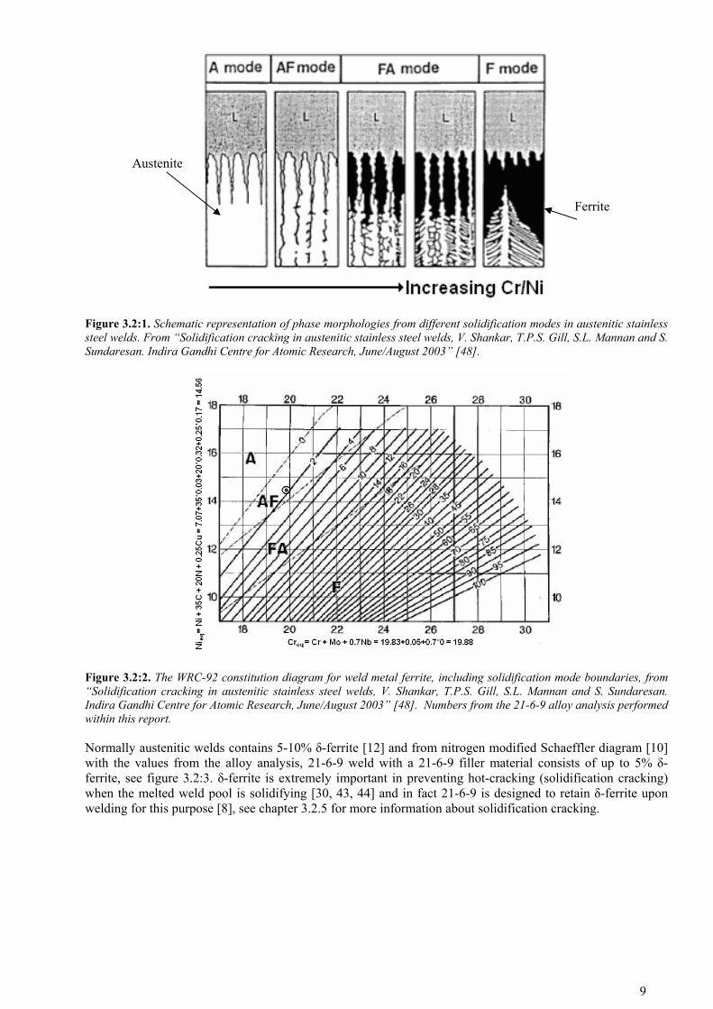
Figure 3.2:1. Schematic representation of phase morphologies from different solidification modes in austenitic stainless steel welds. From “Solidification cracking in austenitic stainless steel welds, V. Shankar, T.P.S. Gill, S.L. Mannan and S. Sundaresan. Indira Gandhi Centre for Atomic Research, June/August 2003” [48].
Figure 3.2:2. The WRC-92 constitution diagram for weld metal ferrite, including solidification mode boundaries, from “Solidification cracking in austenitic stainless steel welds, V. Shankar, T.P.S. Gill, S.L. Mannan and S. Sundaresan. Indira Gandhi Centre for Atomic Research, June/August 2003” [48]. Numbers from the 21-6-9 alloy analysis performed within this report.
Normally austenitic welds contains 5-10% δ-ferrite [12] and from nitrogen modified Schaeffler diagram [10] with the values from the alloy analysis, 21-6-9 weld with a 21-6-9 filler material consists of up to 5% δ-ferrite, see figure 3.2:3. δ-ferrite is extremely important in preventing hot-cracking (solidification cracking) when the melted weld pool is solidifying [30, 43, 44] and in fact 21-6-9 is designed to retain δ-ferrite upon welding for this purpose [8], see chapter 3.2.5 for more information about solidification cracking.
9

Figure 3.2:3. Schaeffler constitution diagram for stainless steel weld metal modified for Mn with N, V, Cu and Al added, from”Weldability of nitrogen strengthen stainless steels, R.H. ESPY, Welding Research supplement 1982” [10]. Numbers from the 21-6-9 alloy analysis performed within this report.
δ-ferrite is ductile at room temperature and at elevated temperature but is brittle at cryogenic temperature and has a cleavage fracture process. This embrittlement of the δ-ferrite creates a network of microcracks ahead of a crack front and leads to a low-energy crack path at cryogenic temperature [11], which has an adverse effect on cryogenic toughness [47], see figure 3.2:4. The effect of this embrittling is usually seen for cryogenic impact tests where the impact results can be dramatically reduced. [9]
The yield strength for austenitic stainless steels seems to increase and ductility decrease with increasing δ-ferrite content, see figure 3.2:5 and 3.2:6.
Figure 3.2:4. Fracture toughness of AWS 316L welds metal at 76
and 4 K as a function of ferrite content, from “Structural alloys, H.I. Henry. Materials at low temperatures, Ed. R. Reed 1983 ASM” [45].
10

Figure 3.2:5. Yield stress versus δ-ferrite content at different temperatures for cast CF8 (ASTM A743-77), the casting equivalent of the 304 wrought stainless steel, from “The effect of delta-ferrite upon the low temperature mechanical properties of centrifugally cast stainless steels, K.S. Lee and David Dew-Hughes. Brookhaven National Lab. Department of Nuclear Energy, 1983” [37].
Figure 3.2:6. Total elongation versus δ-ferrite content at different temperatures for cast CF8 (ASTM A743-77), the casting equivalent of the 304 wrought stainless steel, from “The effect of delta-ferrite upon the low temperature mechanical properties of centrifugally cast stainless steels, K.S. Lee and David Dew-Hughes. Brookhaven National Lab. Department of Nuclear Energy, 1983” [37].
11

When heated the δ-ferrite can decompose to austenite and carbide- or sigma phase, it is also possible with the reverse transformation, see equation 3.2:1. [42]
γσδγδ
+⇔+⇔ 623CM
Equation 3.2:1
δ-ferrite is virtually the same as α-ferrite (ferrite in common diction) [51] and α-ferrite is considered to be hydrogen susceptible due to the BCC structure so δ-ferrite has been for a long time considered as a problem for hydrogen environment applications. But several articles have found no interplay-effect between hydrogen gas and δ-ferrite [7]. So it is an open debate in the literature if δ-ferrite has a negative influence on hydrogen embrittlement.
3.2.1.2 Sigma phase
Sigma phase in stainless steels are an iron – chromium phase with equal atomic percentages of these two elements [24] and precipitates between 866 K and 1173 K in susceptible stainless steels. However, prior cold work can shift the transformation time to shorter times, see figure 3.2:7. [3] The rate of sigma formation can also be increased by operating stresses at these temperatures. [3] ASM handbook reports of sigma phase measurements after 9 hours at 866 K, 922 K and 1033 K with the results of sigma phase rating of 1.2, 1.2 and 2.8 respectively. The numbers should be interpreted as none = 1-1.4 and light = 2.6-3.4 [1].
Figure 3.2:7. Graph showing the conversion rate of delta ferrite to sigma phase in 21-6-9, from “The U.S. NHMFL 60 T Long Pulse Magnet Failure, James R. Sims, Josef B. Schillig and others. IEEE Transactions on applied superconductivity vol. 12, no. 1, MARCH 2002” [28].
Sigma phase preferably forms from δ-ferrite and can be formed directly from the austenite along the grain boundaries in fully austenitic alloys. [3] Sigma nucleates at high energy boundaries and the rate of formation from δ-ferrite seems to be a function of the alloy concentration in the ferrite. [3] Austenite stabilizing elements makes the alloy less susceptible to sigma formation and ferrite stabilizing elements and elements with a high chromium equivalent value promotes the sigma formation (e.g. silicon). [3]
The effect on mechanical properties by sigma phase is depending on test orientation. Ductility, yield- and tensile strength are not or slightly affected in longitudinal direction (no degradation at 293K and at 77K after 30 hours of ageing at 973K [35]), but tensile strength and ductility are severely affected in transverse direction, see figure 3.2:8 and 3.2:9. Impact toughness affects both directions but is more severe in the transverse direction. [2, 35]
12

Figure 3.2:8. Room temperature tensile testing of 21-6-9 with different sigma phase content. [2]
Figure 3.2:9. Room temperature tensile testing of 21-6-9 with different sigma phase content. [2]
Fractures often follow the original ferrite-austenite matrix interface which has become embrittled by the sigma phase. Sigma phase is a good source for crack initiation and propagation due to the extensive plate like morphology and has a grave effect on elevated temperature rupture strength. In lowering the ductility, large and segregated pattern are more severe than small and finely distributed sigma. [3]
The magnitude of the embrittlement is temperature depending, most severe at cryogenic temperatures (one article reports of 10% of the expected value in 77K Charpy impact test [28]), less severe at room temperature and retains reasonable ductility at operating temperatures between 588 and 813 K. [3, 27] One article state that sigma phase has little effect on tensile properties in the temperature range were it forms [29], but severe embrittlement can occur at high strain rates, i.e. shock loading [3]. Therefore care must be taken when handling with the unit when it is out of service, e.g. welding at room temperature, suddenly impact or applied high stresses and when the unit is subject to differential thermal stresses (e.g. cool down). [29]
13
3.2.1.3 Carbide sensitization
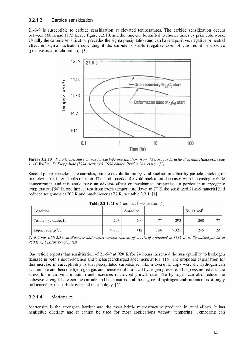
21-6-9 is susceptible to carbide sensitization at elevated temperatures. The carbide sensitization occurs between 866 K and 1173 K, see figure 3.2:10, and the time can be shifted to shorter times by prior cold work. Usually the carbide sensitization precedes the sigma precipitation and can have a positive, negative or neutral effect on sigma nucleation depending if the carbide is stable (negative asset of chromium) or dissolve (positive asset of chromium). [3]
Figure 3.2:10. Time-temperature curves for carbide precipitation, from “Aerospace Structural Metals Handbook code 1314, William D. Klopp June (1994 (revision), 1998 edition Purdue University” [1].
Second phase particles, like carbides, initiate ductile failure by void nucleation either by particle cracking or particle/matrix interface decohesion. The strain needed for void nucleation decreases with increasing carbide concentration and this could have an adverse effect on mechanical properties, in particular at cryogenic temperature. [50] In one impact test from room temperature down to 77 K the sensitized 21-6-9 material had reduced toughness at 200 K and much lower at 77 K, see table 3.2:1. [1]
Table 3.2:1. 21-6-9 sensitized impact tests [1]
Condition Annealeda Sensitizedb
Test temperature, K 293 200 77 293 200 77
Impact energyc, J > 325 312 156 > 325 245 28
21-6-9 bar with 2.54 cm diameter and maxim carbon content of 0.04%.a) Annealed at 1339 K, b) Sensitized for 2h at 950 K, c) Charpy V-notch test
One article reports that sensitization of 21-6-9 at 920 K for 24 hours increased the susceptibility to hydrogen damage in both smooth/notched and uncharged/charged specimens at RT. [15] The proposed explanation for this increase in susceptibility is that precipitated carbides act like irreversible traps were the hydrogen can accumulate and become hydrogen gas and hence exhibit a local hydrogen pressure. This pressure reduces the stress for micro-void initiation and increases microvoid growth rate. The hydrogen can also reduce the cohesive strength between the carbide and base matrix and the degree of hydrogen embrittlement is strongly influenced by the carbide type and morphology. [61]
3.2.1.4 Martensite
Martensite is the strongest, hardest and the most brittle microstructure produced in steel alloys. It has negligible ductility and it cannot be used for most applications without tempering. Tempering can
14

substantially enhance ductility and toughness with some sacrifice in strength and are usually performed around 523 – 923 K which causes the martensite to transform to a ductile ferrite matrix with small and hard cementite particles [51]. The tempering time is usually in the order of 1 hour and further heating at higher temperature (usually above 623 K) causes over-ageing with reduction in strength and increase in toughness. Heating at higher temperatures shortens the time needed and vice versa. [81]
There is generally a temperature interval were tempered martensite embrittlement can occur (usually around 573-623 K) which causes decrease in ductility and toughness. [50, 82]. It is likely that the retained austenite transforms to thin grain boundary films of cementite along the lath boundaries of tempered martensite. This brittle film causes easy crack nucleation sites which then propagate through the ferrite matrix. [50]
The start of the martensite transformation in 21-6-9 is strongly suppressed to lower temperatures by the high amount of austenitic stabilizing elements (e.g. Ni and Mn). It is reported that the 21-6-9 alloy resists temperature-induced martensite transformation down to 20K [39] or to 4 K [31], strain-induced martensite has been reported to occur below 170±10K [17, 40], see figure 3.2:11.
Figure 3.2:11. ά-martensite content versus true strain for hydrogen charged and uncharged Nitronic 40 at different deformation temperatures. Specimens taken out of a 16 mm forged bar, average grain size of 30 µm, solution treated at 1323K for 1h followed by water cooling. Hydrogen charged with 10MPa at 573K for 14 days. From “Effect of hydrogen on 21-7-9 austenitic steel at low temperatures, Luming Ma, Yiyi Li and Goujun Liang, Institute of Metal Research Academia Sinica, Advances in Cryogenic Engineering vol. 34 1988 p 325-333.” [40].
The strain induced martensite only occur after the yield strength has been exceeded, thus indicating that the transformation is associated with plastic deformation. Thereby the amount of martensite should be related to plastic strain instead of stress. [37]
From figure 3.2:11 one can see that hydrogen charging reduces the strain induced martensite, this may results from the increased stacking-fault energy by the interstitially located hydrogen. [40] The present of δ-ferrite decreases the start temperature of martensite by increasing the stability of austenite (by enrichment of Ni) [39], with the same reasoning; sigma phase should also reduce the temperature for martensite transformation due to the even higher Cr/Ni ratio.
Martensite is commonly known to be highly susceptible to hydrogen degradation [1, 4] but hydrogen does not induce martensite transformation and has no apparent effect on the Md temperature [40].
15

3.2.2 Hydrogen embrittlement
Usually one speaks of three different types of hydrogen embrittlement; hydrogen reaction embrittlement (HRE), internal hydrogen embrittlement (IHE) and hydrogen environment embrittlement (HEE), see table 3.2:2.
Table 3.2:2. The different types of hydrogen embrittlement [54]
Type of H embrittlement
Effects Characteristics Examples
Internal hydrogen embrittlement
H absorption at high temperatures and long exposure times
Worst at high temperatures
Almost all alloys except Al, Cu and Ag alloys
H reaction embrittlement
Hydride formation H2O vapour formation CH4 formation
All alloys contain elements that react with H2
Ti alloys
C steels
H environment embrittlement
Loss of ductility Surface cracking Accelerated crack growth
Worst at room temperature
Many Ni-base alloys
HRE
Is due to the reaction of hydrogen with metals (e.g. Ti, Zr and Nb) and alloying elements creating brittle phases [56] and/or vapour (e.g. methane and water) [4]. Hydride formation seems not to occur or at least not to degrade the austenitic phase [4].
IHE
Arises when the hydrogen is distributed through the bulk material and can occur from e.g. melting, welding, corrosion, chemical reactions and when the material is subject to high hydrogen pressure at elevated temperature for long time. The embrittling is reversible and can be undone or almost recovered by heat treatment. The cracks initiate mainly inside the material and the magnitude of the embrittlement is dependent on the hydrogen concentration in the material. [57]
HEE
Hydrogen Environment Embrittlement is a true environmental effect and no hold time in hydrogen environment is required to establish the embrittlement [52]. The hydrogen is swept in to the material by dislocations, and thus plasticity is required for HEE [6, 52]. HEE increases with increasing hydrogen pressure but is sensitive to impurities (e.g. oxygen) in the hydrogen gas and it is enough with small amounts in the order of 1ppm to block the hydrogen ingress [52]. HEE occur from cryogenic to elevated temperature, but is usually most severe at around room temperature [52]. This can be explained by the competitive hydrogen motion between dislocation transport and diffusion. At low temperatures the dislocation moves to slowly to carry the hydrogen to defect sites at sufficient speed and diffusion is negligible at these temperatures. At higher temperatures the dislocations moves faster but the hydrogen moves to fast for any accumulation at defect sites due to the diffusion, [34] see figure 3.2:13. At the vicinity of room temperature an optimum embrittlement condition occurs between these two hydrogen transports. HEE decreases with increasing strain rate due to the increased dislocation motion and thus less hydrogen transport in to the material [59]. In general, susceptible metals exhibit the following behaviour when exposed to hydrogen environment: [52]
Tensile ductility and notch tensile strength are lower in hydrogen than in inert environments Tensile plastic deformation in hydrogen results in surface cracking Subcritical crack growth occurs in hydrogen Cyclic and sustained load crack growth rates are faster in hydrogen than in inert environments
16

Hydrogen embrittlement only occur in plastic strains [6] and thereby the elastic properties and yield strength are unaffected by hydrogen [52].
3.2.2.1 Theory of HEE and IHE
There are many proposed mechanisms for the hydrogen embrittlement that does not occur due to hydride-induced embrittlement and gas pressure, two of these appear to be viable. Hydrogen-enhanced Decohesion mechanism (HEDE) and Hydrogen-Enhanced localized Plasticity mechanism (HELP). [55]
HEDE: Based on the increased solubility of hydrogen in tensile fields which results in a decreased atomic binding energy of the metal lattice. This decrease in atomic binding energy leads to a premature brittle fracture (both transgranular- and intergranular cleavage). [53, 55]
HELP: Same concept as HEDE that hydrogen accumulates at stress fields, the difference is that the hydrogen shields the emerging dislocation motion against other dislocations and grid defects. The stress needed for dislocation motion will be lowered and thereby increasing local dislocation mobility which in the end will cause premature failure. [53, 55]
The interaction of hydrogen with grain boundary particles (e.g. precipitations and carbides) may be another important mechanism. The hydrogen is carried by dislocation motions and gets trapped and accumulated at carbides and precipitations. The cohesive strength between the carbide/precipitation and matrix can be reduced or the hydrogen changes from atomic to molecular hydrogen and reduces the stress required to initiate voids and enhance the growth rate of the voids. [53]
It is not certain if IHE and HEE have an additive effect on tensile properties, but fatigue properties may be subject to an additive effect. [60] Loss of area reduction in hydrogen tensile testing is usually a sign that low cycle fatigue properties have been deteriorated. [57]
3.2.2.2 Influence of high SFE elements and manufacturing methods on the hydrogen embrittlement of 21-6-9
How effective the hydrogen can be transported to the trapping sites impacts the hydrogen embrittlement. Several articles mention that an element that gives a high SFE decreases the hydrogen embrittlement due to the increased cross-slip around trapping sites which reduces the accumulation of hydrogen [8, 14]. Nitrogen seems to decrease SFE and thus increasing hydrogen embrittlement, see figure 3.2:12. [25, 26]
The hydrogen permeability of 21-6-9 is not significantly affected by microstructure or cold work [1, 34], but hydrogen embrittlement are affected by microstructure and composition [1, 25]. In general, annealed materials are less susceptible than worked and wrought alloys are less susceptible than cast alloys. [25, 52]
17
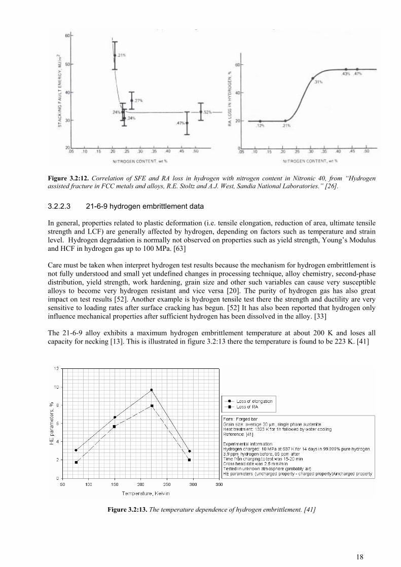
Figure 3.2:12. Correlation of SFE and RA loss in hydrogen with nitrogen content in Nitronic 40, from “Hydrogen assisted fracture in FCC metals and alloys, R.E. Stoltz and A.J. West, Sandia National Laboratories.” [26].
3.2.2.3 21-6-9 hydrogen embrittlement data
In general, properties related to plastic deformation (i.e. tensile elongation, reduction of area, ultimate tensile strength and LCF) are generally affected by hydrogen, depending on factors such as temperature and strain level. Hydrogen degradation is normally not observed on properties such as yield strength, Young’s Modulus and HCF in hydrogen gas up to 100 MPa. [63]
Care must be taken when interpret hydrogen test results because the mechanism for hydrogen embrittlement is not fully understood and small yet undefined changes in processing technique, alloy chemistry, second-phase distribution, yield strength, work hardening, grain size and other such variables can cause very susceptible alloys to become very hydrogen resistant and vice versa [20]. The purity of hydrogen gas has also great impact on test results [52]. Another example is hydrogen tensile test there the strength and ductility are very sensitive to loading rates after surface cracking has begun. [52] It has also been reported that hydrogen only influence mechanical properties after sufficient hydrogen has been dissolved in the alloy. [33]
The 21-6-9 alloy exhibits a maximum hydrogen embrittlement temperature at about 200 K and loses all capacity for necking [13]. This is illustrated in figure 3.2:13 there the temperature is found to be 223 K. [41]
Figure 3.2:13. The temperature dependence of hydrogen embrittlement. [41]
18

The stress-strain behaviour at three different temperatures can be seen in figure 3.2:14. The cryogenic to room temperature tensile strength for hydrogen charged 21-6-9 is slightly higher than uncharged 21-6-9 which also can be seen in 3.2:15. One common method to rank different alloys for susceptibility for hydrogen embrittlement is to use the ratio for the reduction of area between the hydrogen environment and an inert environment, see table 3.2:3.
Table 3.2:3. Hydrogen embrittlement susceptibility rated as the ratio between RA in inert and hydrogen environment
Alloy Fraction of Z H2/He a)
Inconel 600 N/A
Haynes 230 0.41 [85]
Steel 21-6-9 0.99 [7]
Steel 21-6-9, cast 0.94[78]
a) Fraction of reduction of area in a room temperature tensile test in 34.5-69.0 MPa bar hydrogen compared to helium.
The impact toughness from cryogenic to room temperature in figure 3.2:16 is only slightly affected by hydrogen charging and 21-6-9 is even tougher when charged at temperatures higher than 160 K. This is contradicted by figure 3.2:17 where the impact toughness dependence of hydrogen charging pressure is shown for room temperature and at 77 K. Figure 3.2:18 shows the ratio between notched ultimate tensile strength and yield strength which can be seen as a toughness indicator (not common). The lack of data on fracture toughness for hydrogen affected 21-6-9 can be explained by practical difficulties of meeting the plane-strain criteria for the alloy, see chapter 11.2.9, and to the difficulty of instrumenting fracture mechanic experiments in high-pressure hydrogen gas [25].
Figure 3.2:19 and figure 3.2:20 are the results from tensile tests at room temperature and at 1033 K, the test specimens are from a tube that have been exposed to helium or hydrogen gas under high pressure for a long time. The tensile tests show minor differences in strength between helium and hydrogen environment and the as-received part. The ductility is decreased for the gas environment and the hydrogen part has the largest difference with 81% of the elongation of the as-received part at room temperature. Note that the yield strength was probably never exceeded during the long time exposure and there must be plasticity for hydrogen embrittlement to occur, so the magnitude for hydrogen embrittlement at elevated temperatures is difficult to interpret from this experiment.
In one article, [34], test was conducted to investigate the effect of δ-ferrite and carbides on hydrogen embrittlement, see also chapter 3.2.1.1 and 3.2.1.3. In the δ-ferrite experiment the alloy had reduced nitrogen content to increase the δ-ferrite content during heat treatment. Figure 3.2:21 shows the decreased area reduction depending on δ-ferrite content. But the article has no data on experiment on inert environment test so how to interpret the results can be discussed, especially when there seems to be no agreement if δ-ferrite increases the hydrogen embrittlement for an alloy, see chapter 3.2.1.1 . Figure 3.2:22 shows the decrease of area reduction for hydrogen environment for aged 21-6-9 (standard composition). As with the δ-ferrite the reduction of area decreases with increasing ageing, and the increased hydrogen embrittlement can be interpreted as carbide precipitation increases the embrittlement. But the justification give by the authors are quite blurred “The occurrence of carbide in the steel resulted from aging reduces the ductility of the steel and makes the steel sensitive to HE. This implies that the precipitation of carbide may be the important cause for HE sensitivity of the aged steel” [34] and with no experimental data on experiments with inert environment, the results can be discussed.
21-6-9 weld samples from EB and GTA welds seems to be only slightly susceptible for hydrogen embrittlement at room temperature in high-pressure hydrogen gas (no charging), see figure 3.2:23 and figure 3.2:24. Yield and ultimate tensile strength are not reduced by hydrogen gas; the increase in ultimate tensile strength with hydrogen gas is probably from the static hydrogen gas pressure on the test specimens. The base material has a ductility reduction of 6.2% in hydrogen environment, the GTA weld none and the EB weld 5.7%. The base material is not notched sensitive in hydrogen gas, the GTA weld has a ductility reduction of 6.5% and the EB weld has 1.8%. The notch ductility and notch strength ratio indicate that 21-6-9 is not notch
19

sensitive in hydrogen environment [5]. All fractures were completely ductile and no characteristic secondary branching cracks by hydrogen embrittlement were found [5]. With the results from the tensile test and metallographic and fractographic observations the probability of failure for 21-6-9 due to effects of high-pressure hydrogen is low [5]
Figure 3.2:25 and figure 3.2:26 show the results from an experiment where the 21-6-9 TIG weld first was hydrogen charged and then tensile tested in high-pressure hydrogen gas. Yield and ultimate tensile strength show no negative effects from hydrogen (except for the test in 69 MPa hydrogen gases which has a small decrease in yield strength), the increase in strength can be due to the static gas pressure on the test specimens. The largest ductility decrease in total elongation and reduction of area is 9.5% and 16.7% respectively which happened after charging in 69 MPa hydrogen gas at 473 K for 10 days and then tested in air (elongation) and 172 MPa hydrogen gas (reduction of area).
The fracture toughness in hydrogen environment for EB and TIG welds has been investigated, see figure 3.2:27. The plane-strain criterion was never meet but two important aspects can be seen; the TIG and EB welds have toughness similar to the base metal and hydrogen environment seems to not decrease the fracture toughness at room temperature [5].
Figure 3.2:14. Stress-strain behaviour for 21-6-9 between cryogenic and room temperature when hydrogen charged
20

Figure 3.2:15. Effect of hydrogen on 21-6-9 tensile strength at cryogenic temperature
Figure 3.2:16. Effect of hydrogen on 21-6-9 impact toughness at cryogenic temperature
21

Figure 3.2:17. 21-6-9 impact toughness between cryogenic and room temperature as a function of hydrogen pressure
Figure 3.2:18. The ratio between notched ultimate tensile strength and yield strength as a function of temperature when hydrogen charged
22

Figure 3.2:19. 21-6-9 ultimate tensile and yield strength at room temperature (RT) and at 1033 K after long time exposure in high temperature and hydrogen pressure environment
Figure 3.2:20. 21-6-9 elongation after long time exposure in high temperature and hydrogen pressure environment
Figure 3.2:21. Loss in reduction of area as a function of ferrite content when hydrogen charged for 21-6-9
23

Figure 3.2:22. Loss in reduction of area as a function of ageing time when hydrogen charged for 21-6-9
Figure 3.2:23. Smooth and notched ultimate tensile and yield strength in hydrogen gas for TIG and EB welded 21-6-9
24

Figure 3.2:24. Smooth and notched ductility in hydrogen gas for TIG and EB welded 21-6-9
Figure 3.2:25. Ultimate tensile and yield strength of 21-6-9 TIG weld in high-pressure hydrogen gas after hydrogen charging
25

Figure 3.2:26. Ductility of 21-6-9 TIG weld in high-pressure hydrogen gas after hydrogen charging
Figure 3.2:27. Apparent fracture toughness for 21-6-9 TIG and EB welds in hydrogen gas
3.2.2.4 Effect by hydrogen on creep, LCF, HCF and fracture mechanics
General information on how hydrogen affects these material properties.
3.2.2.4.1 Creep
Life reductions in high pressure hydrogen are generally not severe, creep ductility may be slightly affected by hydrogen environment but generally fall within expected data scatter for inert environment. The primary observation is an increase in creep strain rate, leading to reduction in time to rupture. [52]
3.2.2.4.2 LCF and HCF
In general, alloys which exhibit only slight degradation in tensile properties in high-pressure hydrogen are similar unaffected in LCF by HEE. Materials that exhibit some degree of tensile property degradation in high-
26

pressure hydrogen have reduced LCF by HEE. [52] The greatest reduction occurs below room temperature and above cryogenic temperature [52], i.e. the maximum embrittlement temperature, see figure 3.2:13.
The requirement to exceed the yield strength (achieve plasticity) for hydrogen environment embrittlement to be active, indicates that the hydrogen environment will have slight, if any, influence on crack initiation. It is generally considered that the life expectancy in HCF is 90% crack initiation and 10% crack propagation and thereby no significant life degradation would be expected from the hydrogen. [52]
3.2.2.4.3 Fracture mechanics
21-6-9 exhibit a fracture toughness decrease of about 20% in high-pressure hydrogen gas compared to tests in air and in most cases both internal (charging) and external hydrogen gas has a greater effect on fracture toughness and tearing modulus than tests without internal hydrogen. [25] Hydrogen environment can influence both the threshold stress intensity and crack propagation rate. KITh is degraded most severely near room temperature (at the maximum embrittlement temperature, se figure 3.2:13), and approaches the unaffected value at cryogenic and elevated temperatures. Increasing hydrogen pressure decreases the threshold stress intensity significantly at the beginning until flatten out. [52]
3.2.3 Formability
Can be cold worked by the same equipment and techniques used for Type 300 series stainless steel, however it is necessary to choose equipment with the proper capacity due to the increased yield strength and work hardening rate of 21-6-9. [1]
3.2.4 Machinability
Due to the higher work hardening rates, the cutting speed for 21-6-9 are about 20% lower when carbide tools are used and about 33% lower with high speed steel tooling than Type 304 and 316 stainless steel. [1] 21-6-9 cutting speed with high speed steels are 17-21 m/min. [77]
3.2.5 Welding properties
The weldability and performance of 21-6-9 weldments are rated as very good [10] and being comparable to the conventional austenitic stainless steels e.g. 304L and 316L [10, 67]. The alloy can be welded by several techniques e.g. TIG, EB and laser. High nitrogen content (~0.30%) seem to reduce the susceptibility for carbide sensitization when welding and thereby making the cooling rates from weld temperatures not to be so critical in nitrogen strengthened stainless steels [10]. Using filler metals with nitrogen content near that of the base metal can give a porous weld that is stronger than the base metal [10] but too high nitrogen content in 21-6-9 (>~0.35%) can give problems with excessive weld pool eruptions when TIG-welding [43] or porosity [67], outgasing can also occur during EB-welding [66b].
The nitrogen transfer across the liquid metal-atmosphere interface (in both directions) can be inhibited by the present of oxygen. Only ionized nitrogen can diffuse into the liquid metal and this is dependent on surface active elements or the presence of an arc for the dissociation of N2. When nitrogen ions are present in the atmosphere, the equilibrium is with nitrogen ions in the liquid metal and not with nitrogen gas (N2). This will increase the solubility relationship and give higher amounts of nitrogen at equilibrium. So for 21-6-9 (there the nitrogen content in the alloy is close to the equilibrium with one atmosphere pressure of nitrogen gas) there is a tendency to pick up the nitrogen ions from the “ionized-area” produced by the welding arc. When the welding “tip” moves on, the over-saturated nitrogen in the liquid metal attempts to readjust to the N2 equilibrium in the atmosphere but present oxygen at the liquid metal surface blocks the diffusion out of the liquid metal and spitting can occur when the nitrogen forces it way out of the liquid metal surface. For the most welding situations, nitrogen gas is not present in significant amounts when shielding gas is used and impurities of oxygen in the shielding gas can also be enough quantity to prevent weld pool eruptions. When welding in vacuum (EB-welding), the nitrogen in the liquid metal will establish a new equilibrium with the vacuum which can causes the nitrogen to diffuse out of the liquid metal (so called outgasing). The time
27

dependence of the nitrogen diffusion must also be considered because the liquid metal is solidifying after the welding “tip” has left. [21]
Solidification cracking (i.e. hot-cracking) is mainly due to low melting grain boundary films formed during the last stages of solidification. The susceptibility is increased by constituents that promote liquid phases, e.g. P, S and Si, and high levels of Mn may be beneficial in decreasing the susceptible for cracking by tying up S and Si. [67] Thus one article about weldabiltiy in high N and Mn austenitic stainless steels claims that the primary responsibility for hot-cracking when ferrite is absence in 21-6-9 are films formed by Mn and P (Mn-P eutectic at 960°C) [43]. Ferrite has been found to greatly reduce the susceptibility for solidification cracking which is the cause for the intestinally alloying to retain ferrite in welds for austenitic stainless steels, see chapter 3.2.1.1. Welding under stress increases the susceptibility for solidification cracking because the liquid film can not respond to deformation and even though 21-6-9 have good weldability it would be wise to investigate the susceptibility of solidification in 21-6-9 under these circumstances.
High-energy density welds (e.g. EB and laser) can shift the solidification transition from primary austenite to primary ferrite to higher Creq/Nieq ratios due to the rapid solidification velocities and cooling rates, see figure 3.2:1. This can have a drastic effect on weld quality, performance and lead to problems with solidification cracking [67] due to the reduced ferrite content.
The sigmajig value for 21-6-9 is reported to be 234 MPa [79], see table 3.2:4. The value should be interpret as range of values “The stress value ranges from the stress above which cracking first occurs to the stress at which specimen separation occurs. In some very crack-resistant materials these stresses will coincide” [87].
Welding may result in delta ferrite which can reduce the hydrogen embrittlement and cryogenic properties, see chapter 3.2.1.1.
Table 3.2:4. Range of threshold stress values for different alloys in sigmajig test.
Alloy First cracking, MPa
Specimen separation, MPa
21-6-9a 234 not reported 304b 241 368 316b 99 345
JBK-75b 178 200 800b 99 189
A-286b 149 161 Aluminumb 6 109
a) Can be found in [79], b) can be found in [88].
3.2.6 Heat treatment
Stress relieving is used to achieve best all-around properties and for operating temperatures below 977 K. The temperature range for stress relieving is 755-1033 K, temperatures between 755 K and 950 K will have little effect on mechanical properties unless percent cold reduction is high. Above 950 K the change in mechanical properties will occur more rapidly and temperature over 1089 K causes rapid softening. [77]
Annealing is used for best stress rupture life and for operating temperatures between 977 K and 1144 K. General annealing temperatures are between 1255 K and 1450 K [77] followed by quenching or rapid cooling [1], temperature as low as 1172K can be used [77].
Heat treating at 978 K or higher causes boron to cosegregate with nitrogen to the surface and form boron nitride. This film uniformly covers the surface after 1 hour and is stable down to room temperature. [1]
Vacuum annealing around 1478 K and higher causes vaporization of manganese from grain boundaries with the results of intergranular porosity and deterioration of mechanical properties. [1]
3.2.7 Hot workability and grain size
28

21-6-9 can be forged, hot rolled, hot headed and upset. Preheating is not required and the alloy can be rapidly cooled without any danger of cracking, anneal after forging for best corrosion resistance. 21-6-9 can be hot worked as low as 922 K. [77]
Maximum grain size for 21-6-9 sheet and plate (AMS 5595) are ASTM 7 for thickness below 4.76 mm and ASTM 3 when thickness exceeds 4.76 mm.
3.2.8 Interface consideration
Copper from the combustion chamber may be deposited on the inside of the nozzle. It is known that copper may cause cracking in superalloys due to low-melting-point penetration of grain boundaries during welding. It is also known that liquid copper deposited on some alloys can cause severe embrittlement.
In reference [18] conventional tensile test with plated copper and copper-braze alloys was conducted on commercial 21-6-9. The test was conducted with a tensile-testing machine equipped with a vacuum furnace and the cupper/braze was plated on one side of the gauge length of the tensile bar prior to testing. A copper wire was also wrapped around the gauge length to reduce the rapid copper evaporation in the vacuum furnace which leads to insufficient copper for the growing cracks during the tensile test. No problems in wetting were encountered for the 21-6-9 alloy.
The results from the tensile testing are that 21-6-9 is severely embrittled by copper and high copper content braze alloy at the melting temperature for the embrittling substance, see table 3.2:5. The stress-strain curves for the embrittling elements were the same as the control samples until fracture, therefore the yield strength and ultimate tensile strength were unaffected by the liquid. A general invasion of grain boundaries to a depth of a few grains was frequently (but not always) observed in highly embrittled samples. Failure occurred by the propagation of cracks filled with the embrittling liquid metal and the cracks reached a depth far beyond the general invasion of the grain boundaries, see figure 3.2:29. Thus the possibility that some liquid metal had migrate after the crack formation cannot be ruled out in this experiment. Fractrographic investigation revealed that non-embrittled 21-6-9 failed by ductile formation and that the highly embrittled 21-6-9 failed intergranularly, see 3.2:30. A test was also conducted there copper containing braze was plated on a piece of 21-6-9 and then heated to ~50° above the braze flow temperature for 5 min then rapidly cooled in the furnace. The results indicate that there is no correlation between the severity of embrittlement and the degree of penetration of the copper containing braze alloy into a stress-free surface, see table 3.2:6. But the article is quite vague if the tensile test in table 3.2:6 was performed as the same way as in table 3.2:5 and if the result means that measuring liquid metal penetration is meaningless for deciding the alloys susceptibility for liquid metal embrittlement.
Table 3.2:5. Effect of liquid copper on the total elongation and tensile strength for 21-6-9, from “Embrittlement of several stainless steels by liquid copper and liquid braze, Clinton Heiple, William Bennet and Thomas Rising, Materials Science and Engineering, 52 (1982) 277-289” [18]
Liquid metal Test temperature, K Elv Ellm RE, % YSv UTSv YSlm UTSlm
Cu 1373 86 0.5 99 43 MPa 43 MPa 41 MPa 41 MPaElv is the total elongation to fracture in vacuum, Elm is the total elongation to fracture in contact with liquid copper and RE is the percentage reduction in elongation caused by the liquid copper.
Table 3.2:6. A comparison of stress-free penetration versus embrittlement for 21-6-9 , from “Embrittlement of several stainless steels by liquid copper and liquid braze, Clinton Heiple, William Bennet and Thomas Rising, Materials Science and Engineering, 52 (1982) 277-289 “[18]
Braze alloy Test temperature, K Maximum penetration, μm Reduction in ductility, %
85Cu-8Sn-7Ag 1273 >70 99
85Ag-15Mn 1323 0 2
60Au-20Cu-20Ag 1273 >70 19
65Ag-20Cu-15Pd 1173 1 91
57Ag-33Cu-7Sn-3Mn 1073 3 87
29

Figure 3.2:29. Secondary cracks filled with braze metal (arrow) in a 21-6-9 tensile bar tested in contact with an 85Cu-8Sn-7Ag braze, from “Embrittlement of several stainless steels by liquid copper and liquid braze, Clinton Heiple, William Bennet and Thomas Rising, Materials Science and Engineering, 52 (1982) 277-289 “[18].
Figure 3.2:30. Fractographic examination for 21-6-9 tensile bar tested in a) vacuum at 1373 K and showing ductile fracture, b) vacuum and in contact with copper at 1373 K and showing brittle intergranual fracture c) vacuum and in contact with insufficient amount of copper at 1373 K showing the transition between ductile fracture (no/low copper) and the brittle intergranual fracture (copper). From “Embrittlement of several stainless steels by liquid copper and liquid braze, Clinton Heiple, William Bennet and Thomas Rising, Materials Science and Engineering, 52 (1982) 277-289”.
Plastic deformation associated with crack initiation and possibly crack propagation is generally believed to be a requirement for embrittlement by liquid metals/alloys. Several mechanisms have been postulated for liquid metal embrittlement and it seems like that the most accepted theory is that the liquid metal reduces the strength of the atomic bonds of the solid. Failure occurs as the liquid comes in contact with the atomic bonds at the crack tip and the crack propagates as fast as the liquid is supplied to the crack tip. The stress-strain behaviour agrees theoretically with the experimental observation (see above) but the need for plastic deformation is unclear in this model. The need for plastic deformation has been explained in various dislocation mechanisms, e.g. the chemisorptions of liquid metal eases the nucleation of dislocations and opening of crack tips due the reduced deformation of the solid metal lattice at the surface against the liquid
30

metal. Further work is thus required to determine how liquid metal embrittlement occurs and if there is only one mechanism active. [18]
The liquid metal embrittlement usually occurs at the melting point of the embrittling liquid and generally vanishes at some higher temperatures, but for some systems the embrittlement can occur below and above the melting temperature. The temperature range extends from few degrees to several hundreds and raised strain rate increases the embrittling temperature range, see figure 3.2:31. [18]
Figure 3.2:31. A schematic plot of elongation versus test temperature for liquid metal embrittlement, from “Embrittlement of several stainless steels by liquid copper and liquid braze, Clinton Heiple, William Bennet and Thomas Rising, Materials Science and Engineering, 52 (1982) 277-289” [18].
A weld test was also conducted in [18], copper was plated to be in the HAZ (but not in contact with the weld pool) in 21-6-9 disks and two types of TIG welds were made with argon gas as shielding. The copper near the weld pool melted during welding and the geometry was selected to produce severe thermal stresses during cooling. The results were nearly continuous cracking in the outer HAZ of the smaller diameter circular weld and occasional cracks were seen outside of the larger diameter weld bead. Cracks were also seen where the weld pool had unintentionally touched the copper plating. [18] It has also been observed elsewhere that 21-6-9 cracks when copper is present during welding [1]
21-6-9 has been successfully brazed with copper to produce braze joints with yield strength in excess of the parent material and only slightly degraded mechanical properties at liquid nitrogen temperature. The braze joints were produced by coating 7.62 μm thick electro-deposited copper layer or 25.4 μm thick copper foil on the parent metal and subsequent heat-treatment were 1453 K and 1473 K respectively for 30 min. Excessive amount of copper lead to liquid metal attack on the grain boundaries adjacent to the bonding line. Optimum bonding condition are achieved when there is just enough copper present to remove oxide form the parent metal surface and promote diffusional bonding across the interface [16] and liquid copper embrittlement are not generally a problem because normally the joints are not stressed during the brazing [18].
3.2.9 Elevated temperature use
The stress relieving temperature range for 21-6-9 are between 755 K and 1033 K. Temperatures between 755 K and 950 K will have little effect on mechanical properties of cold reduced material unless the percent cold reduction is high and temperatures above 950 K will reduce mechanical properties more rapidly. 21-6-9 start to recrystallize above 1048 K [36] and temperatures above 1089 K will cause rapid softening. The alloy is not recommended for use above 1144 K. [77]
The carbide precipitation range is between 866 K and 1173 K which is the same for sigma phase transformation. Stress-rupture strength at 100 hours decreases from 234 MPa at 922 K to 70 MPa at 1089 K. The creep strength decreases from 99 MPa at 922 K to 44 MPa at 1005 K for 0.1% strain in 1000 hours. [65]
A fairly considered maximum service temperature for 21-6-9 in a sandwich nozzle or its part should be 820 K if limited carbide precipitation is allowed and 870 K with no safety margin against cold works influence on carbide precipitation and sigma phase formation.
31

3.3 AVAILABILITY, COST AND RANGE OF USES FOR 21-6-9
3.3.1 Availability
21-6-9 can be cast and is available in following forms:
Table 3.3:1. Available forms for 21-6-9 (Nitronic 40). Form AMS ASME ASTM Bars, wire, forgings, extrusions 5656
A276, A314, A473, A580
Sheet, strip and plate 5595 SA412 A412 Tubing seamless 5562 Tubing, welded and drawn 5561
Cast none available
Welding wire 5818
The available can be rated as standard and 21-6-9 is produced by following companies:
• Carpenter Technology Corporation, trade name Carpenter 21-6-9 [89]. • Allegheny Ludlum, trade name 219 [90].
3.3.2 Cost
A cost analysis between interesting alloys for this nozzle application was made from available Volvo Aero cost data and cost inquires to various manufacturers. Inconel 600 sheet was set as the cost reference, see table 3.3:2. The 21-6-9 alloy seems to be a very cost effective material for the nozzle compared to Inconel 600 and Haynes 230.
Table 3.3:2. Comparable cost index for forging and sheet Sheet (3.2 mm) Forging
Material Index Standard Index Standard
Inconel 600 1.00 AMS5540 3.74 AMS5665
Inconel 625 - - 4.29 AMS 5666
Haynes 230 1.21 AMS 5878 4.23 AMS 5891 21-6-9 0.64 AMS 5595 0.84 AMS 5656
A286 1.09 AMS 5525 1.34 AMS 5895?
32

3.3.3 Range of uses
21-6-9 is commonly used as pressure vessels, seamless tubing for aircraft hydraulic systems and air craft engines components. 21-6-9 was chosen for a high pressure gas system for liquid propulsion test facility (design temperature between 200 K and 311 K) at NASA’s John C. Stennis Space Center [74]. Due to the high cryogenic stability of the austenitic phase, high cryogenic strength (compared to i.e. 300-series) and good cryogenic toughness the 21-6-9 has been used at cryogenic temperatures for various magnetic applications (e.g. dipole magnet [75], see also [28]). The alloy has also been used in the SSME as a low pressure turbopump discharge duct for liquid hydrogen [69], see figure 3.3:1. The alloy might also have been used for pressure vessels for hydrogen containment [76].
Figure 3.3:1. The SSME showing the Low Pressure Fuel Turbopump (LPFTP) discharge duct, from “Replacement of environmental hazardous corrosion protective plate on the SSME using wire arc sprayed aluminium, Ronald L. Daniel, Heather L. Sanders, Mitchell J. Mendrek, NASA-Cr-202081 “ [69].
33

4 EXPERIMENTS
The tensile test on laser welds and the liquid copper embrittlement test were done on 21-6-9 sheet fulfilling the AMS 5595 material specification. The TIG weld specimens came from a left over piece of sheet and the grain size did not fulfil the ASM 5595 standard. The laser welds were welded on a 1 mm thick sheet and the TIG weld was welded on a 4.7 mm thick sheet. The 21-6-9 stripes in the copper embrittlement experiment came from the 1 mm thick sheet. See appendix for mount identification number and welding parameters.
4.1 LIQUID COPPER EMBRITTLEMENT
When the rocket engine is at use, copper from the combustion chamber can be eroded and then plated on the inside of the nozzle. Liquid copper embrittlement can be a problem for several alloys, in chapter 3.2.8 this phenomena is reviewed and it is found from article [18] that 21-6-9 is severely embrittled by liquid copper.
4.1.1 Purpose
The purpose of this experiment was to examine the dissolution and diffusion depth of the liquid copper and by a simple procedure try to embrittle the 21-6-9 by liquid copper and compare the embrittlement with the tensile test in chapter 3.2.8.
4.1.2 Procedure
The idea was to coat metal stripes with copper powder and then cause plasticity but not failure with attached weights at liquid copper temperature, see figure 4.1:1. A vice was used to fasten the metal stripes in the cylinder, but to be sure that the stripes were attached at elevated temperature a TIG weld was used.
Copper powder (max 500µm grain size and 99.8% purity) and some braze binder was mixed and then placed at the anchored end prior to heating, possible oxide was first removed with a grinding paper. This copper paste was dried at room temperature for some hours before the test setup was placed in the furnace.
The test setup was placed in a metal box to reduce the problem with wetting and the heat treatment was done at 1373 K for 10 minutes in a vacuum furnace.
Figure 4.1:1. The liquid copper embrittlement test setup
34

With the use of the Euler-Bernoulli equation the weight could be estimated, see equation 4.1:1.
612*22
(max) 23 wtmaL
wtmaLh
IFLh
yx ===σ Equation 4.1:1
stripe theof thicknesststripe theof width wstripe theoflength the L
gravity todue a weight
thethe
onacceleratitheofmassthem
=====
Problem occurred when trying to establish a value for the yield strength, no reliable values at these temperatures could be found. When plasticity occurs the Euler-Bernoulli equation is not longer valid so equation 4.1:1 was more as an aid to estimate values. With data from the copper embrittlement article [18] and Haynes 188 product data sheet and some qualified guessing the following stress values in table 4.1:1 were chosen for the Cu embrittlement test.
Table 4.1:1. Yield and ultimate tensile strength at 1373 K and chosen stress values for Cu embrittlement test YSv UTSv YSlm UTSlm 21-6-9a 43 43 41 41 JBK-75a 3,9 4,8 4,0 4,8 Haynes 188b 64 130 - - Chosen stress for Cu liquid embrittlement test, MPa 21-6-9 41 33 JBK-75 33 4 Haynes 188 75
Subscript v refers to test at vacuum and lm refers to test when liquid copper is present, a) see reference [18], no misprint for JBK-75 values b) data taken from Haynes 188 product data sheet at Haynes International’s homepage
It was practically difficult to attach the stripes so the length of the stripes correspond the estimated stress from the Euler-Bernoulli equation (4.1:1). After the TIG-welding there were no measurements on the length of the stripes and a post-test measurement was made. The results from this measurement are that the lengths after the tests are about the same as chosen in table 4.1:1 (according to the Euler-Bernoulli equation) but the true elongation is not known.
The 33 MPa 21-6-9, 33 MPa JBK-75 and the Haynes 188 stripe were cut off and a cross-section piece of the copper embedded area was cut out from each stripe. This cross-section piece was mounted and sample prepared by regular procedure. The 21-6-9 sample was etched slightly with Nital. The samples were examined in a regular optical microscope. The dissolution and diffusion depth were measured from the bottom of the test specimen to the base metal–copper interface and this value was subtracted from a measured copper free base metal thickness.
4.1.3 Results
In this report only the results for JBK-75 and Haynes 188 are reported, for more detailed information see [Iron-Base Superalloy JBK 75 - An Investigation on Its Potential for Use in Space Nozzle Walls, Elin Karlsson, Master thesis in mechanical engineering. Chalmers University of Technology].
Photos taken from the optical microscope reveal a large crack in the 21-6-9 test specimen, see figure 4.1:2. Copper is found through the entire cross-section of this crack, but copper has floated around the test specimen so the copper has migrated from the top and the bottom. After etching, the range of copper migration is more clearly visible, see figure 4.1:3. In figure 4.1:4, it is clear that the crack has gone through half of the test specimen along the short-side. Perhaps it is possible to determine the origin of the crack by examine the
35

fracture surface in a SEM, because the fracture should be ductile if the crack occurred prior to the heat treatment and brittle if copper was present, see figure 3.2:30. The crack might have emerged from the first attempts to fasten the test specimens to the large metal cylinders by using a vice or it might have happened during welding.
Weight
z
Figure 4.1:2. Un-etched photo of the 21-6-9 test specimen, 50 x magnification
Figure 4.1:3. Etched photo of the 21-6-9 test specimen, 50 x magnification.
36

z
Figure 4.1:4. Photo of the remaining piece of the cut-of 21-6-9 test specimen. a) Bottom view, ~ 3 x magnification. The sample prepared piece is taken from the right side; see figure 4.1:2, b) side view, ~3 x magnification
The copper coating is clearly visible in figure 4.1:2 and measurement of the dissolution and diffusion depth can be seen in figure 4.1:5. The liquid copper seems to have dissolved the base metal for the first 19 µm and diffused 211 µm into the material. There were an absence of “marks” at the bottom side after etching (except at the vicinity of the crack) this indicates that the etching did not reveal any grain boundaries and thus the marks are from copper migration, see figure 4.1:3. The dissolution and diffusion depths of liquid copper for the three tested alloys can be seen in table 4.1:2. No failure occurred for the three alloys and the only crack found was the large crack in 21-6-9. It is difficult to achieve plasticity without causing failure due to the load and not by possible embrittlement by this method, a more suitable test would be a tensile test as in article [18].
Figure 4.1:5. Average Cu dissolution and diffusion depths in the 21-6-9 test specimen, 100 x magnification
Table 4.1:2. Cu dissolution and diffusion depths for the three tested alloys
Alloy Maximum Cu dissolution depth, µm Maximum Cu diffusion depth, µm
Fe-Ni alloys JBK 75 20 270 Austenitic stainless steel 21-6-9 30 229 Cobolt alloy Haynes 188 20 100
4.1.4 Summary of the liquid copper embrittlement test
The alloys JBK-75, 21-6-9, and Haynes 188 were tested for liquid copper embrittlement at 1373 K for 10 min. No failure occurred and the maximum dissolution and diffusion depth were 20, 30, 20 µm and 270, 229, 100
37

µm respectively. In 21-6-9 a large crack emerged, but at present time it is unclear if the crack was present before the liquid copper test or if it happened during the test. A fracture surface examination in a SEM should be able to determine the origin of the crack.
4.2 TENSILE TEST
The purposes of this experiment were to give tensile data on laser weld at room temperature and at elevated temperature and examine the effect of heat treatment on tensile properties.
4.2.1 Performance
Two laser welds were made on two equivalent sheets of 21-6-9, from these two welds six room temperature tensile specimens and three high temperature specimens were made. Two room temperature specimens and two high temperature specimens from an unwelded sheet were also made. Two tensile specimens and one left-over laser weld were heat-treated at 1255 K ±8 K for 30 min ±5 min in a vacuum furnace and then cooled with argon gas. The test temperatures were room temperature and 866 K for the elevated temperature (ET) test. See appendix A for more information.
One sample from each group was prepared for examination by regular mounting, grinding and polishing, see appendix A. The samples were etched with 60% HNO3 at 1.1 V for some seconds for grain size measurements. Regular optical microscope was used for determination of failure site (fusion zone, HAZ or base metal).
4.2.2 Results
The results from the tensile testing can be seen in table 4.2:1. The yield strength is almost the same for the weld and the base metal, independent of test temperature. The welds are in average 93% of the ultimate tensile strength and 45% of the elongation of the unwelded values. The heat treatment decreased the weld yield strength and ultimate tensile strength by 11% and 5% respectively and increased the weld elongation by 9%. All welded specimens failed at the fusion zone which is normal for welded austenitic stainless steels [11]. Most of the unwelded specimens, in particular the elevated test specimens, failed near one of the ends. All failures were ductile and had the same appearances, see figure 4.2:1 for the fracture site for room temperature tensile tests.
Table 4.2:1. Results from the tensile testing of laser welded and unwelded 21-6-9.
Identification number
Yield strength, MPa Ultimate tensile strength, MPa Elongationa, % Type
11 461 761 20 Weld, RT
23 459 765 23 Weld, RT
Average value 460 763 21.5
12 407 725 23 Weld, RT, heat-treated
24 409 729 24 Weld, RT, heat-treated
Average value 408 727 23.5
13 204 n/ab 15 Weld, ET
21 205 426 14 Weld, ET
Average value 204.5 426 14.5
31 211 465 31 Base, ET
32 207 473 33 Base, ET
Average value 209 469 32
33 461 810 44 Base, RT
34 456 805 50 Base, RT
Average value 458.5 807.5 47 RT = 293 K, ET = 866 K, Base = unwelded metal, a) A50 % measurements, b) unknown complication with the tensile testing machine.
38

Figure 4.2:1. Fracture site for room temperature tensile tests, 500 x magnification a) base metal, the highly elongated grains are clearly visible b) fracture in fusion zone, the dendritic structure is clearly visible and has been smeared out.
The tensile test results compared to GMA tensile tested welds for the same temperatures shows that the laser weld had little higher YS and UTS and much lower elongation compared to the GMA values (36% at RT and 26% at ET), see figure 11.3:1 and figure 11.3:2.
A hardness measurement was conducted on two laser welds that were left-over from the tensile test specimen manufacturing, one of the welds was also heat treated at the same time as the tensile test specimen. TIG-weld measurements are done for reference. For the non heat-treated laser weld the highest hardness was found in the HAZ, which can be explained by dislocation hardening by stresses during welding. The heat-treated laser weld has a quite large decrease in hardness, see table 4.2:2.
Table 4.2:2. Results from the hardness measurement.
Hardness, Vickers
1 2 3 Average value
Hardness, HRBa
Base 235 228 227 230 97
HAZ 257 265 268 263
Laser weld
FZ 229 235 239 234
Base 204 209 210 208 93
HAZ 206 210 185 200
Laser weld,
Heat-treated FZ 204 202 196 201
Base 217 223 219 220 95
HAZ 227 223 214 221
TIG weld
FZ 228 214 226 223 400 x magnification, mass = 300g, a) ASM 5595 criteria of less than 100 HRB
39

The grain size was also measured for the three weld specimens and only in the heat-treated laser weld could the HAZ be measured. The heat-treatment increased the grain size by 2.4 ASTM values and caused large grain size increase in the HAZ, see table 4.2:3. TIG-weld measurement is done for reference.
Table 4.2:3. Results from the grain size measurement
ASTM grain size
Base 9,7 Laser weld
HAZa -
Base 7,3 Laser weld
Heat-treatedc HAZb 1,4
Base 6,9 TIG weld
HAZa - Grain size measurements conducted by the intercept method, a) difficult to distinguish the HAZ from the unaffected zone, b) not the same accuracy as in the base metal measurements c) heat-treated at 1255 K ±8 K for 30 min ±5 min in a vacuum furnace, then cooled with argon gas
The result of heat treatment on the laser weld can be seen in figure 4.2:2 and it is clear that extensive grain growth has occurred in the HAZ and fusion zone, compare figure 4.2:2b with 4.3:2b. The cause for the reduction in strength for the heat-treated laser weld seems to be grain growth in the fusion zone and in the heat-affected zone and possibly annealing of the dislocation hardening that may occur in the HAZ during welding.
Figure 4.2:2. Photos from heat-treated laser weld a) photo from the HAZ-FZ area, 100 x magnifications b) photo over the central FZ. The black bar is equal to 100 µm, 200 x magnifications.
4.2.3 Summary of the tensile testing
The welds have in average 93% of the ultimate tensile strength and 45% of the elongation of the unwelded values. The heat treatment decreased the weld yield strength and ultimate tensile strength by 11% and 5% respectively and increased the weld elongation by 9%. The reduction of strength is likely from extensive grain growth in the fusion zone and in the heat-affected zone and possibly annealing of the dislocation hardening that may occur in the HAZ during welding. All welded specimens failed at the fusion zone and all failures were ductile and had the same appearances.
40

4.3 EXAMINATION OF WELD PROPERTIES FOR TIG AND LASER WELD
The purpose was to examine the difference between a wide TIG-weld and a narrow laser-weld with reference to differences in the fusion zone, HAZ, nitrogen content, δ-ferrite content and the effect of heat-treatment on the δ-ferrite content .The heat-treated laser weld is the same non-tensile tested laser weld as in the previous chapter.
4.3.1 Procedure
To measure the retained ferrite content in welds and casting is not so easy and to overcome the large disagreement between measurements and techniques the ferrite number was adopted and approved by the Welding Research Council (WRC), American Welding Society (AWS) and other organizations during the 1970´s. The ferrite number is an arbitrary standardized value for the ferrite content in austenitic stainless steels measured by standardized magnetic techniques and should not be confused with percent or volume percent ferrite. There a number of commercially available instruments for detecting ferrite contents in welds, e.g. Magne gage, Severn gage and Ferrite scope (e.g. FERITSCOPE®MP30E manufactured by Helmut Fischer http://www.ndtsupply.com/assets/pdf-files/N-FT-FCM.pdf). It is found inappropriate and inaccurate to use magnetic methods for measuring ferrite content in laser welds because the high cooling rate conditions achieved during laser welds creates a small weld bed which cause practical limitations for conducting measurements. [70] More accurate models and techniques for deciding ferrite content are constantly developed, e.g. in reference [71] and [70].
Volvo Powertrain in Gothenburg has a mobile x-ray diffractometer (Xstress 3000) and the idea was to examine the possible differences in δ-ferrite between the TIG and laser weld and if it possible to reduce the δ-ferrite content by heat treatment. The first idea was to cut out the fusion zone, but this is practically very difficult for the laser weld due to the small size. But the x-ray diffractometer at Volvo Powertrain has a minimum focal diameter of 1 mm2 which is the same area as the laser weld bed so no cutting were necessary.
The cross section of the welds were cut out and then mounted, grinded and polished by standard sample preparation methods, see appendix A for mount identification number. Electrolytic etching with oxalic acid at 6 V was used to reveal carbide precipitation, to reveal the retained δ-ferrite electrolytic etching with 20% NaOH at 20 V was used, see reference [73] for more information and “how to use”.
The intercept method at three random locations was used for grain size measurements. The hardness was measured in Vickers and three measurements where done for each area of interest. A nitrogen measurement on the TIG-weld and on the base metal for reference was performed to examine the nitrogen outgasing/absorption issue when welding, see chapter 3.2.5, a Leco TC136 was used. Four blocks from the base metal were cut out and four fusion zone parts from the TIG-weld were also cut out. Nitrogen measurement for the laser weld was ruled out due to practical limitations of collecting enough material from the very thin laser weld.
41

4.3.2 Results
No carbide precipitation at grain boundaries were found in the TIG or laser weld, see figure 4.3:1.
Figure 4.3:1. Electrolytic etching with oxalic acid at 6 V to reveal carbide precipitations in TIG (left) and laser weld (right).
The differences in the retained δ-ferrite structure between the wide TIG weld and the thin laser weld can be seen in figure 4.3:2 and one can clearly see that the dendritic structure is much smaller and finer distributed in the laser weld because of the higher cooling rates with the laser welding technique [19].
Figure 4.3:2. Electrolytic etching with 20% NaOH at 20 V to reveal the retained δ-ferrite in TIG and laser weld, a) TIG, b) laser
The results from the x-ray diffraction measurement can be seen in table 4.3:1. There is a difference in δ-ferrite content between the TIG weld and laser weld and by heating the laser weld at 1255 K for 30 minutes the δ-ferrite content is reduced. These values should not be interpreted as absolute values because the measurement was only performed on a cross-section of the three dimensional structure of the dendrites on one part of the weld. Small measured values (like P1 and P2) can also be due to small facet on the sample surface, i.e. the surface is not perfectly flat.
42

Table 4.3:1. Measured δ-ferrite content in three different welds by x-ray diffraction δ-ferrite [%] Mount number / type of weld Fusion zone Base metal, P1 Base metal, P2 M06-2172, heat treated laser 1.5 0, (0.1) 0, (0.2) M06-2175, laser weld 3.3 0, (0.2) 0, (0.2) M06-2257, TIG weld 5.5 0 1.5
Volvo Powertrain project number: 2077005, registration number 91572-07-30.
The result from the measurement of the nitrogen content in the fusion zone of a TIG weld is that the base metal has a nitrogen content of 0.31% and the fusion zone has a nitrogen content of 0.23%.
4.3.3 Summary
No carbide precipitation at grain boundaries could be found and the differences between TIG and laser weld regarding retained δ-ferrite are the much finer distribution of dendrites in the laser weld. The results from the x-ray diffraction measurement are that the TIG weld has more retained δ-ferrite than the laser weld and heat-treatment at 1255 K for 30 min reduces the δ-ferrite content but at the expense of strength and grain growth. The fusion zone had 25.8% less nitrogen content than the base metal.
43

5 DISCUSSION
The δ-ferrite
The inventors of Nitronic 40, Armco, state in one of their product brochures that weldments made with Nitronic 40W exhibits good cryogenic toughness when thickness is less than 6.35 mm. For thickness greater than 6.35 mm nickel-based filler metals are suggested.[66b] Unfortunately no numbers are given for the “good” cryogenic toughness for Nitronic 40W and the numbers in table 11.3:4 are from thick section welds (20-50 mm) and can thereby be unfair to 40W. The embrittlement of δ-ferrite depends on its amount, orientation and distribution [80] which can have an influence on the applicability of 21-6-9 for a sandwich nozzle (compare with figure 4.3:2).
The brittle nature of the retained ferrite in the weld causes difficulties to maintain cryogenic toughness in the Nitronic alloys [49] and reported values for weld toughness at 4 K are 57 MPa×m½ and 82 MPa×m½ for TIG and GMA weld process respectively [58]. According to ASM handbook [1] the general fracture toughness for austenitic welds are 50-70% of the base metals [23] and even though the cryogenic fracture toughness of 21-6-9 base metal seems to be very high, see 11.2.9, it is necessary to consider further fracture toughness decreases from e.g. hydrogen gas (reported a 20% decrease for 21-6-9) and strain-induced martensite.
Small changes in the ferrite content can give significant effect on the fracture toughness, recall figure 3.2:4. It was mentioned in chapter 3.2.5 that high-energy density weld processes like laser and EB-welding could shift the solidification transition from primary austenite to primary ferrite to higher Creq/Nieq ratios. This could lead to problems with weld quality and solidification cracking due to the lower ferrite content. This is interesting because choosing a high-energy density weld method (e.g. laser) over e.g. TIG-weld the amount of retained ferrite can be reduced and hence obtains better cryogenic toughness. The results of the x-ray measurement on the ferrite content between a laser and TIG weld performed within this report may support this assumption (3.3% ferrite in the laser weld compared to 5.5% in the TIG-weld). It may also be possible to further decrease the ferrite content in the laser weld by optimizing the welding process (output power, welding speed and so on) without causing any problems with weld quality.
Unfortunately the nitrogen measurement of the TIG weld can not be evaluated because the filler metal used is of unknown origin. An x-ray measurement was conducted on pieces from the fusion zone and the result is that the filler metal is a type of 21-6-9 alloy, see table 12.1:2. But it is not possible to decide if it the same as the base metal (i.e. the nitrogen content reduces during welding) or if it was an e.g. 40W filler metal (which has reduced nitrogen content).
From an iron-carbon phase diagram one can see that the δ-ferrite is unstable and transforms to austenite between 1183 K and 1673 K. The 21-6-9 iron-carbon phase diagram is a bit different due to the alloying elements, but this kind of temperature window for ferrite to austenite transformation still exists. D.A. Wigley conducted a comprehensive study of the possibility to heat treat Nitronic 40 to decrease the amount of δ-ferrite [80]. The heat treatments were performed from 1373 K to 1573 K between 4 hours and 12.5 hours and the δ-ferrite was decreased at the most from 4.73% to 2.96% after 8 hours at 1478 K at the expense of extreme grain growth (grain size less than ASTM 0). This study failed to transform all of the δ-ferrite but it is reported that Armco managed in one of theirs studies to transform all of the δ-ferrite after 12.5 hours at 1423 K and after 4.5 hours at 1473 K. The recommended upper temperature limit for removal of δ-ferrite is 1473 K, at 1573 K the austenite in 21-6-9 is unstable and transforms to δ-ferrite [80]. The heat treatment of a laser weld within this report verifies that it is possible to decrease the amount of retained δ-ferrite by heat treatment at the expense of strength and it is possible that a lower temperature results in a lesser loss of strength and less grain growth.
By using filler metals of different alloys it is possible to make 21-6-9 welds without retained δ-ferrite, for example nickel-based alloys like the Inconel series. Examples of nickel based alloys that have similar strength and ductility as the 21-6-9 filler metal and have good fracture toughness at cryogenic temperature (see table 11.3:1, 11.3:3 and 11.3:4) are Inconel 625 and Inconel 625+. However, Inconel 625 seems to be more susceptible for hydrogen embrittlement than the 21-6-9 alloy [62] so it is recommended to investigate possible hydrogen embrittlement susceptibility and temperature capability for the weldments when filler metal is used.
44
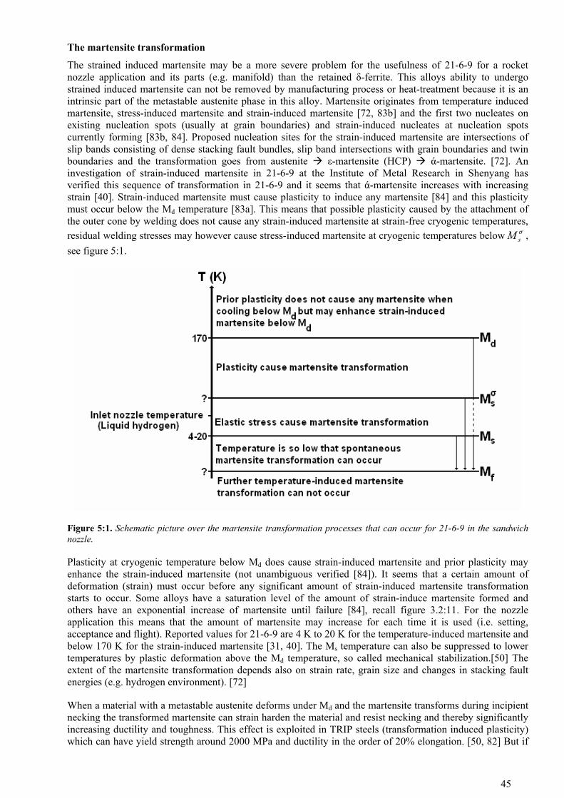
The martensite transformation
The strained induced martensite may be a more severe problem for the usefulness of 21-6-9 for a rocket nozzle application and its parts (e.g. manifold) than the retained δ-ferrite. This alloys ability to undergo strained induced martensite can not be removed by manufacturing process or heat-treatment because it is an intrinsic part of the metastable austenite phase in this alloy. Martensite originates from temperature induced martensite, stress-induced martensite and strain-induced martensite [72, 83b] and the first two nucleates on existing nucleation spots (usually at grain boundaries) and strain-induced nucleates at nucleation spots currently forming [83b, 84]. Proposed nucleation sites for the strain-induced martensite are intersections of slip bands consisting of dense stacking fault bundles, slip band intersections with grain boundaries and twin boundaries and the transformation goes from austenite ε-martensite (HCP) ά-martensite. [72]. An investigation of strain-induced martensite in 21-6-9 at the Institute of Metal Research in Shenyang has verified this sequence of transformation in 21-6-9 and it seems that ά-martensite increases with increasing strain [40]. Strain-induced martensite must cause plasticity to induce any martensite [84] and this plasticity must occur below the Md temperature [83a]. This means that possible plasticity caused by the attachment of the outer cone by welding does not cause any strain-induced martensite at strain-free cryogenic temperatures, residual welding stresses may however cause stress-induced martensite at cryogenic temperatures below , see figure 5:1.
σsM
Figure 5:1. Schematic picture over the martensite transformation processes that can occur for 21-6-9 in the sandwich nozzle.
Plasticity at cryogenic temperature below Md does cause strain-induced martensite and prior plasticity may enhance the strain-induced martensite (not unambiguous verified [84]). It seems that a certain amount of deformation (strain) must occur before any significant amount of strain-induced martensite transformation starts to occur. Some alloys have a saturation level of the amount of strain-induce martensite formed and others have an exponential increase of martensite until failure [84], recall figure 3.2:11. For the nozzle application this means that the amount of martensite may increase for each time it is used (i.e. setting, acceptance and flight). Reported values for 21-6-9 are 4 K to 20 K for the temperature-induced martensite and below 170 K for the strain-induced martensite [31, 40]. The Ms temperature can also be suppressed to lower temperatures by plastic deformation above the Md temperature, so called mechanical stabilization.[50] The extent of the martensite transformation depends also on strain rate, grain size and changes in stacking fault energies (e.g. hydrogen environment). [72]
When a material with a metastable austenite deforms under Md and the martensite transforms during incipient necking the transformed martensite can strain harden the material and resist necking and thereby significantly increasing ductility and toughness. This effect is exploited in TRIP steels (transformation induced plasticity) which can have yield strength around 2000 MPa and ductility in the order of 20% elongation. [50, 82] But if
45
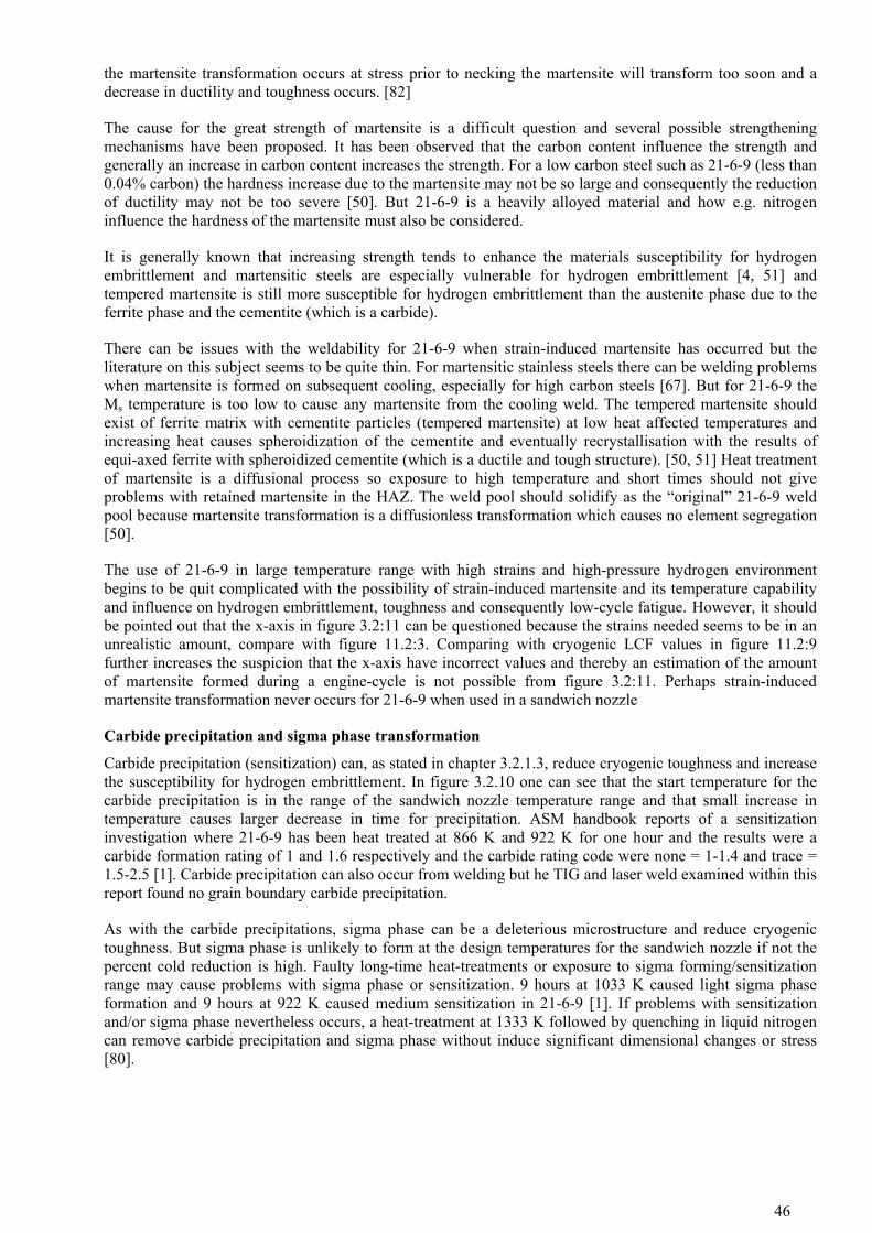
the martensite transformation occurs at stress prior to necking the martensite will transform too soon and a decrease in ductility and toughness occurs. [82]
The cause for the great strength of martensite is a difficult question and several possible strengthening mechanisms have been proposed. It has been observed that the carbon content influence the strength and generally an increase in carbon content increases the strength. For a low carbon steel such as 21-6-9 (less than 0.04% carbon) the hardness increase due to the martensite may not be so large and consequently the reduction of ductility may not be too severe [50]. But 21-6-9 is a heavily alloyed material and how e.g. nitrogen influence the hardness of the martensite must also be considered.
It is generally known that increasing strength tends to enhance the materials susceptibility for hydrogen embrittlement and martensitic steels are especially vulnerable for hydrogen embrittlement [4, 51] and tempered martensite is still more susceptible for hydrogen embrittlement than the austenite phase due to the ferrite phase and the cementite (which is a carbide).
There can be issues with the weldability for 21-6-9 when strain-induced martensite has occurred but the literature on this subject seems to be quite thin. For martensitic stainless steels there can be welding problems when martensite is formed on subsequent cooling, especially for high carbon steels [67]. But for 21-6-9 the Ms temperature is too low to cause any martensite from the cooling weld. The tempered martensite should exist of ferrite matrix with cementite particles (tempered martensite) at low heat affected temperatures and increasing heat causes spheroidization of the cementite and eventually recrystallisation with the results of equi-axed ferrite with spheroidized cementite (which is a ductile and tough structure). [50, 51] Heat treatment of martensite is a diffusional process so exposure to high temperature and short times should not give problems with retained martensite in the HAZ. The weld pool should solidify as the “original” 21-6-9 weld pool because martensite transformation is a diffusionless transformation which causes no element segregation [50].
The use of 21-6-9 in large temperature range with high strains and high-pressure hydrogen environment begins to be quit complicated with the possibility of strain-induced martensite and its temperature capability and influence on hydrogen embrittlement, toughness and consequently low-cycle fatigue. However, it should be pointed out that the x-axis in figure 3.2:11 can be questioned because the strains needed seems to be in an unrealistic amount, compare with figure 11.2:3. Comparing with cryogenic LCF values in figure 11.2:9 further increases the suspicion that the x-axis have incorrect values and thereby an estimation of the amount of martensite formed during a engine-cycle is not possible from figure 3.2:11. Perhaps strain-induced martensite transformation never occurs for 21-6-9 when used in a sandwich nozzle
Carbide precipitation and sigma phase transformation
Carbide precipitation (sensitization) can, as stated in chapter 3.2.1.3, reduce cryogenic toughness and increase the susceptibility for hydrogen embrittlement. In figure 3.2.10 one can see that the start temperature for the carbide precipitation is in the range of the sandwich nozzle temperature range and that small increase in temperature causes larger decrease in time for precipitation. ASM handbook reports of a sensitization investigation where 21-6-9 has been heat treated at 866 K and 922 K for one hour and the results were a carbide formation rating of 1 and 1.6 respectively and the carbide rating code were none = 1-1.4 and trace = 1.5-2.5 [1]. Carbide precipitation can also occur from welding but he TIG and laser weld examined within this report found no grain boundary carbide precipitation.
As with the carbide precipitations, sigma phase can be a deleterious microstructure and reduce cryogenic toughness. But sigma phase is unlikely to form at the design temperatures for the sandwich nozzle if not the percent cold reduction is high. Faulty long-time heat-treatments or exposure to sigma forming/sensitization range may cause problems with sigma phase or sensitization. 9 hours at 1033 K caused light sigma phase formation and 9 hours at 922 K caused medium sensitization in 21-6-9 [1]. If problems with sensitization and/or sigma phase nevertheless occurs, a heat-treatment at 1333 K followed by quenching in liquid nitrogen can remove carbide precipitation and sigma phase without induce significant dimensional changes or stress [80].
46

6 MATERIAL EVALUATION MATRIX
Table 6:1. Material evaluation matrix based on literature data.
“+ = Acceptable”, “0 = Possibly/need further investigation” and “- = No” 21-6-9
Comparable strength with Inconel 600 and Haynes 230. +
Comparable ductility with Inconel 600 and Haynes 230. +
Metallurgic stability.
• Carbide sensitization and sigma phase
• Martensite transformation and tempering of martensite
+
0
Low sensitivity to hydrogen embrittlement for base material and welds.
• LCF in hydrogen environment
+
0
Shall be possible to repair. +
Sensitivity to copper contamination.
• At liquid copper temperatures
• Welding when copper is present
-
-
Good welding properties. +
No heat-treatment needed after welding. +
Good thermo-mechanical fatigue properties in the temperature range. This includes good isothermal LCF properties with and without dwell time and fatigue loading where both the mechanical and thermal loading changes with time. 0
Good HCF properties. +
Good Fracture Toughness. +
Good CGR threshold properties. +
Good CGR properties in the linear elastic and inelastic fracture mechanics regime. 0
Good resistance to creep. +
Comparable thermal expansion with Inconel 600 and Haynes 230. -
Comparable thermal conductivity with Inconel 600 and Haynes 230. +
Possible to cold-form without following heat treatment. +
Good machining properties for milling of channels. +
47

Good hot working properties. +
Availability material. +
Availability process. +
Lower density compared with Inconel 600 and Haynes 230. +
48

7 CONCLUSIONS
From the literature review it may be concluded that the 21-6-9 alloy possesses most of the properties suitable for a sandwich nozzle. The alloy has comparable strength with Inconel 600 and Haynes 230 and exhibits a ductile failure for the entire temperature range. The fracture toughness is high and 21-6-9 has a comparable thermal conductivity with Inconel 600 and Haynes 230 but a higher thermal expansion compared to Inconel 600 and Haynes 230. The alloy is regarded to have low susceptibility for hydrogen embrittlement but there is a lack of LCF measurements in hydrogen environment. 21-6-9 also exhibit good weldability, formability and machinability with comparable low cost and standard availability. It is available in sheet, plate, forgings and tubes and can be cast. Carbide sensitization or sigma phase formation should not be a problem for 21-6-9 when used below 820 K and plated copper on the inside of the nozzle can cause welding problems when repairing.
However, the retained ferrite and the metastable austenite of 21-6-9 and their single or cooperative influence on material and mechanical properties could be described as potential “show stoppers” and must be further investigated.
The retained δ-ferrite can be a problem for cryogenic toughness and may increase the hydrogen embrittlement susceptibility. High-energy density welding (e.g. laser) can reduce the amount of retained δ-ferrite in the welds and heat-treatment can reduce the amount of δ-ferrite at the expense of large grain growth and decrease in strength. If δ-ferrite free welds are desired, e.g. Ni-based alloys can be used. Examples of Ni-based alloys with comparable strength, ductility and toughness are Inconel 625 and Inconel 625+.
Strain and stress-induced martensite can be a more severe problem than the retained δ-ferrite and strain-induced martensite may occur during the engine-cycle and stress-induced martensite may occur from residual stresses after manufacturing. The martensite content may increase with increasing engine-cycles and martensite is vulnerable to hydrogen embrittlement and the tougher tempered martensite may exist at some parts of the nozzle.
49

8 PROPOSALS FOR FURTHER WORK
Feasibility tests for this alloy should be:
• Cryogenic fracture toughness measurements on 21-6-9 welds.
• LCF measurements with hydrogen environment or at cryogenic temperature for a welded and unwelded sample.
• Examine if martensite transformation can occur in a sandwich nozzle made of 21-6-9.
• Examine the impact of martensite on LCF and fracture toughness properties in hydrogen environment and at cryogenic temperature.
Important tests:
• Evaluate the risk of solidification cracking under high degree of restraint.
• Evaluate a heat-treatment procedures for minimum grain growth when stress-relieving and for possible δ-ferrite reduction
• Investigate if changes in laser welding parameters can decrease the amount of retained δ-ferrite without causing weldability problems.
• Investigate if TIG welding causes nitrogen reduction in the fusion zone.
• Investigation if Ni based alloys is suitable as filler metals for 21-6-9.
50
9 ABBREVATIONS
Ablative cooling - combustion gas-side wall material is sacrificed by melting, vaporization and chemical changes to dissipate heat ASM - Aerospace Structural Materials ASME - American society of mechanical engineers ASTM - American society for testing and materials AWS - American welding society Base metal - Unwelded metal, see BM BM - Base metal, i.e. unwelded material CT - Cryogenic temperature EB - Electron Beam welding ET - Elevated temperature FZ - Fusion zone, the part of the weld that has been melted GMA - Gas Metal Arch, another abbreviation for MIG GTA - Gas Tungsten Arc, another abbreviation for Tungsten Inert Gas (TIG) HAZ - Heat-affected zone HCF - High cycle fatigue HE - Hydrogen embrittlement HEE - Hydrogen environment embrittlement HRE - Hydrogen reaction embrittlement IHE - Internal hydrogen embrittlement KIth - Threshold stress intensity (MPa×m½) for crack propagation LCF - Low cycle fatigue MIG - Metal inert gas, see GMA MAG - Metal Arc Gas Nitronic 40 - Same as 21-6-9 but with twice the allowed carbon content RT - Room temperature, usually between 293 and 298 K SEM - Scanning Electron Microscope SFE - Stacking Fault Energy SIM - Strain-induced martensite SSME - Space Shuttle Main Engine TIG - Tungsten Inert Gas, see GTA UTS - Ultimate Tensile Strength YS - Yield Strength XRD - X-Ray Diffraction
51

10 REFERENCES
1. Aerospace Structural Metals Handbook code 1314, William D. Klopp June (1994 (revision), 1998 edition Purdue University
2. Study of the formation and effects of sigma phase in 21-6-9 stainless steels , Carol L. Packard, Martin C. Mataya, Carl M. Edstrom, Rockwell International (1981)
3. Appendix (review of literature) to [2]
4. Hydrogen and Advanced Aerospace Materials, H. G. Nelson, NASA-Ames research centre, Sample Quarterly, Oct. 1988.
5. Tensile and fracture properties of austenitic stainless steel 21-6-9 in high pressure hydrogen gas, Rickard R. Vandervoort, Metals Engineering Quarterly February
6. Liquid-fuel rocket engine for the space shuttle, Louis H. Freeman, January 1977
7. Effect of gaseous hydrogen on the mechanical properties of metal used in the petroleum industry, Jewett. Corrosion (Preprint 18-79), pp 151-160.
8. Effect of weld composition and microstructure on hydrogen assisted fracture of austenitic stainless steels, J.A. Brooks, A.J. West and A.W. Thompson, Metallurgical Transactions A volume 14A January 1983
9. Thick-section weldments in 21-6-9 and 316LN stainless steel for fusion energy applications, D.J. Alexander and G.M. Goodwin, ORNL DoE DE-AC05-84OR21400
10. Weldability of nitrogen strengthen stainless steels, R.H. ESPY, Welding Research supplement 1982
11. Fracture toughness of austenitic stainless steels and their welds, W.J. Mills, ASM handbook vol. 19, Fatigued fracture (1996)
12. Austenitic stainless steels, microstructure and mechanical properties, P. Marshall, Springer (juillet 1984), ISBN 0-85334-277-6
13. The effect of temperature and strain rate on the tensile properties of hydrogen charged 304L, 21-6-9 and JBK 75, J. Holbrook at Battelle’s Columbus Laboratories and A.J. West at Sandia National Laboratories
14. Ductility losses in austenitic stainless steel caused by hydrogen, Anthony W. Thompson, Hydrogen in Metals, AMS 1973. pp 91-102.
15. Notch and hydrogen effects on sensitized 21-6-9 stainless steel, G.R. Caskey Jr, TMS-AIME Fall Meeting at Milwaukee 1979
16. Preliminary results on the development of vacuum-brazed joints for cryogenic wind tunnel aerofoil models, D. A. Wigley, P.G. Sandefur and P.L. Lawing, Aug 1 1981
17. The microstructure and properties of a cryogenic steel Fe-21Cr-6Ni-9Mn-N, Y. Li, Shoushen Cai, Yikui Xu, Bainian Quian, Chungan Fan, Xuejun Zhao and Guojun Liang, Institute of Metal Research, Academia Sinica Shenyang
18. Embrittlement of several stainless steels by liquid copper and liquid braze, Clinton Heiple, William Bennet and Thomas Rising, Materials Science and Engineering, 52 (1982) 277-289
19. Phase transformation in metals and alloys 2:nd edition, D.A. Porter and K.E. Easterling, CRC Press 2004, page 221
20. Hydrogen effect on the tensile properties of 21-6-9 stainless steel, Anton J. West Jr. and McIntyre R. Louthan Jr., Metallurgical Transactions A volume 13A November 1982
52

21. Private mail communication with Dr. Alec Mitchell, professor emeritus at University of British Columbia
22. Internal Volvo Aero report
23. Welding for Cryogenic Service, T.A. Siewert and C.N. McCowan, National Institute of Standards and Technology, ASM handbook vol. 6 “Welding, brazing & soldering” 1997
24. Sigma – an Unwanted constituent in Stainless weld metal, Lorin K. Poole, Metal progress June 1954
25. Technical Reference on Hydrogen Compatibility of Materials, Austenitic Stainless Steel 21-6-9, C. San Marchi, Sandia National Laboratories, DE-AC04-94AL85000
26. Hydrogen assisted fracture in FCC metals and alloys, R.E. Stoltz and A.J. West, Sandia National Laboratories
27. Materials selection considerations for thermal process equipment, U.S. Department of Energy, http://www1.eere.energy.gov/industry/bestpractices/pdfs/proc_heat_tech_brief.pdf
28. The U.S. NHMFL 60 T Long Pulse Magnet Failure, James R. Sims, Josef B. Schillig, Gregory S. Boebinger, Hideyoshi Coe, Alan W. Paris, Michael J. Gordon, Michael D. Pacheco, Terri G. Abeln, Richard G. Hoagland, Martin C. Mataya, Ke Han, and Aferdita Ishmaku, IEEE Transactions on applied superconductivity VOL. 12, NO. 1, MARCH 2002
29. Sigma phase embrittlement of stainless steel in FCC service, Jorge Hau and Antonio Seijas, Lloyd’s Register Capstone, Inc., Corrosion NACExpo 2006 61st annual conference & exposition
30. Embrittlement of Austenitic Stainless Steel Welds, S.A. David, J. M. Vitek and D.J. Alexander, Journal of Nondestructive Evaluation, Vol. 15 1996
31. Mechanical properties of Inconel 625 welds in 21-6-9 stainless steel at 4 K, R.R. Vandervoort, Cryogenics August 1979
32. Evaluation of candidate Stirling engine heater tube alloys for 1000 hours at 760°C, John A. Misencik, NASA Lewis Research Center, November 1980, NASA TM-81578
33. Hydrogen effects in austenitic stainless steels, T.P. Perng, and C.J. Altstetter, Materials science and engineering, A129 (1990) p99-107
34. Effect of hydrogen on the microstructure, mechanical properties and phase transformations in austenitic steels, Y.Y. Li and Z.S. Xing, Institute of metal research, Academia Sinica, Journal of Nuclear Materials 169 151-157 (1989)
35. Effects of welding on weldment mechanical performance in two austenitic steels, Michael Jay Strum, Master thesis June 1982, Lawrence Berkeley Laboratory University of California, LBL-14750
36. Microstructural stability of 21-6-9 stainless steel, Robert W. Krenzer and Elane C. Sanderson, Rockwell International (May 1978), RFP-2668
37. The effect of delta-ferrite upon the low temperature mechanical properties of centrifugally cast stainless steels, K.S. Lee and David Dew-Hughes, Brookhaven National Lab. Department of Nuclear Energy, 1983
38. Aspects of fracture mechanics in cryogenic model design Part II – NTF Materials, J.C. Newman and W. B. Lisagor, NASA Langley Research Center
39. Effect of δ-ferrite on the stability of austenite and the properties of stainless steel at cryogenic temperatures, A.P. Gulyayev and N.A. Kozlova, 1968
40. Effect of hydrogen on 21-7-9 austenitic steel at low temperatures, Luming Ma, Yiyi Li and
53

Goujun Liang, Institute of Metal Research Academia Sinica, Advances in Cryogenic Engineering vol. 34 1988 p 325-333.
41. Effect of hydrogen on cryogenic mechanical properties of Cr-Ni-Mn-N austenitic steels, Luming MA, Goujun Liang, Jun Tan, Lijian Rong and Yiyi Li, Institute of Metal Research, Chinese Academy of Sciences, Journal of Materials Science and Technology vol. 15 1999 p 67-70.
42. Fracture and the formation of sigma phase, M23C6 and austenite from delta-ferrite in an AISI 304L stainless steel, C.C. Tseng, Y. Sheen, S.W. Thompson, M.C. Mataya and G. Krauss, Metallurgical and materials transactions, vol. 25A June 1994
43. Weldability of high N, high Mn austenitic stainless steel, J.A. Brooks, Welding Journal. Vol. 54, no. 6, June 1975
44. Weld cracking of austenitic stainless steels – effects of impurities and minor elements, J.A. Brooks, A.W. Thompson and J.C. Williams, Physical Metallurgy of Metal Joining, Proceedings, Symposium, St Louis, Missouri; 16-17 Oct. 1980. pp. 117-136.
45. Structural alloys, H.I. Henry, Materials at low temperatures, Ed. R. Reed 1983 ASM
46. Engineering data on new aerospace structural materials, O.L. Deel, P.E. Ruff and H. Mindlin, Battelle Columbus Laboratories, June 1973, AFML-TR-73-114
47. Evaluation of Weld fillers to join nitrogen strengthened austenitic stainless steels for cryogenic applications (fusion and MHD energy), R.H. Espy, Armco Research & Technology
48. Solidification cracking in austenitic stainless steel welds, V. Shankar, T.P.S. Gill, S.L. Mannan and S. Sundaresan, Indira Gandhi Centre for Atomic Research, June/August 2003.
49. Cryogenic steels, J.W Morris Jr, Encyclopaedia of Material Science and Engineering vol2, 1986, p 956-960
50. Steels, Microstructure and Properties second edition, R.W.K. Honeycombe and H.K.D H. Bhadeshia 1995, Butterworth Heinemann. p: 83,105, 108, 176, 182, 278
51. Materials science and engineering an introduction 6:ed 2003, W.D. Callister Jr, John Wiley & Sons Inc. p: 279, 320-323, 588
52. Hydrogen embrittlement – Rocket Engine Applications, Leslie G. Fritzemier and Willis T. Chandler, Rockwell International, Superalloys, supercomposites and superceramics 1989.
53. Mechanism for hydrogen embrittlement in Ni-base alloys: A selective review, Ali R. Massih, Division of Solid Mechanics, Luleå University of Technology 1999
54. Materials for advanced space propulsion systems, Neil E. Paton. M&S Engineering, 1991, 21-29
55. Hydrogen embrittlement, Universtität des Saarlandes, Saarbrücken, http://www.uni-saarland.de/fak8/wwm/research/phd_barnoush/hydrogen.pdf
56. Hydrogen embrittlement and its control in the hydrogen-fueled engine systems, Chandler. Rockwell International BC 86-61, 1986.
57. Internal Volvo Aero report
58. Austenitic stainless steels for cryogenic service, E.N.C. Dalder and M.C. Juhas, Lawrence Livermore National Laboratory, UCRL-92882
59. Low-cycle fatigue of Fe-Cr-Ni-Austenite and Ni-base alloys in high pressure hydrogen, Rie, Ruge, Kohler. Proceedings JIMIS-2, Hydrogen in Metals, pp 529-532.
60. Hydrogen Embrittlement Research: A Rocketdyne Overview, Fritzemeier, Walter. Hydrogen effects on Material Behaviour, The Minerals, Metals & Materials Society, 1990, pp 941-954.
54

61. Väteförsprödning - mekanismer, orsaker och åtgärder, Skogsmo, Nordänger. IVF-skrift 97823, 1997.
62. Influence of Gaseous Hydrogen on Metals, Walter. Final Report, NASA-CR-124410, 1973.
63. Internal Volvo Aero report
64. Internal Volvo Aero report
65. Armco Nitronic 40 Product Data Bulletin No. S-2
66. Armco Nitronic 40 Product Data Bulletin, Alloy Digest Inc.
66b. Armco Nitronic 40 stainless steel product description
67. Selection of wrought austenitic stainless steels, J. A. Brooks and J. C. Lippold , ASM handbook vol. 6 “Welding, brazing & soldering” 1997, p: 459, 462, 678
68. Various public sandwich nozzle articles at www.volvo.com under space propulsion
69. Replacement of environmental hazardous corrosion protective plate on the SSME using wire arc sprayed aluminium, Ronald L. Daniel, Heather L. Sanders, Mitchell J. Mendrek, NASA-Cr-202081
70. Improved ferrite number prediction model that accounts for cooling rate effects – Part 1: Model Development, J.M. Vitek, S.A. David and C.R. Hinman, Welding Journal, January 2003
71. Measuring the residual ferrite content of rapidly solidifying stainless steel alloys, J.W. Elmer and T.W. Eagar, Welding Research Supplement, April 1990
72. Effect of Strain Rate on Stress-Strain Behaviour of Alloy 309 and 304L Austenitic Stainless Steel Joshua A. Lichtenfeld, Martin C. Mataya and Chester J. Van Tyne, Metallurgical and Materials transactions Volume 37A, January 2006
73. Wrought Stainless Steels, George F. Vander Voort and Hughston M. James, ASM handbook 9th edition vol. 9 “Metallography and Microstructures” 1985
74. Cryogenic piping material selection for the component test facility (CTF), William W. St. Cyr, John C. Stennis Space Center, AIAA-91-2170-CP
75. Construction and results of the 50 mm short R&D dipole magnets, G.H. Morgan, M. Anerella, J. Cottingham and others, Brookhaven National Laboratory, IEEE 1991
76. Inertia welding of Nitronic 40 pressure vessels for hydrogen containment, C.H. Cadden, Sandia National Laboratories, ASM conference March 2004
77. Carpenter 21Cr-6Ni-9Mn alloy data, Product Datasheet, Ed. 1986.
78. Hydrogen-environment embrittlement and its control in high pressure hydrogen/oxygen rocket engines, Chandler. N89-12654
79. Assessment of hot cracking in a dissimilar metal weld between HP 9-4-20 and 21-6-9 steels, M.W. Richey and G.M. Goodwin, Recent Trends in Welding Science and Technology; Gatlinburg, Tennessee; USA; 14-18 May 1989. pp. 655-659. 1990
80. The metallurgical and mechanical properties at low temperature of Nitronic 40 with particular reference to its use in the construction of models for cryogenic wind tunnels, D.A. Wigley, NASA Contractor Report 165907 April 1982
81. Metalliska material, Kompendium I metalliska material för M2, Chalmers University of Technology, p:189-200
55
82. Deformation and Fracture Mechanics of Engineering Materials 4th edition, Richard, W. Hertzberg, John Wiley & Sons, Inc 1996, p: 433, 462
83a. Modelling strain induced martensite formation during forming, Lars-Erik Lindgren, Department of Applied Physics and Mechanical Formation, Luleå University of Technology
83b. Private telephone and mail communication with professor Lars-Erik Lindgren at Department of Applied Physics and Mechanical Formation, Luleå University of Technology
84. Private telephone communication with Peter Hedström doctoral candidate, Division of Engineering Materials at Luleå University of Technology
85. Assessment of candidate rocket propulsion materials in a gaseous hydrogen environment, Gibson et.al. PRR-SA-APD 05 May 1992, pp 85-94.
86. Internal Volvo Aero report
87. Development of a new hot-cracking test – the sigmajg, G. Goodwin, Weld. J. Vol. 66, no. 2, pp. 33S-38S
88. Results in weldability of dissimilar 5000 and 6000 aluminium alloy combinations, M. Atwell (2000), MSc. Thesis, The Ohio State University, EWI report MR0007
89. Carpenter Technology Corporation, www.cartech.com
90. Allegheny Ludlum, www.alleghenyludlum.com
91. Special Metals, Publication SMC027, March 2004.
92. Haynes 230 Alloy, Haynes, Publication H-3000H, 2004.
93. M.F. Rothman et al, New Materials for Fabricated Gas Turbine Hot Section Components.
56

11 PHYSICAL AND MECHANICAL PROPERTIES
11.1 PHYSICAL PROPERTIES
11.1.1 Density and melting range
Table 11.1:1. Density and melting range for Inconel 600, Haynes 230 and 21-6-9.
Alloy Density (g/cm3)
Melting point (K)
Inconel 600 8.41 [64] 1627[91]
Haynes 230 8.97 [64] 1574 [92]
Steel 21-6-9 7.83 [1] 1627 [1]
11.1.2 Dynamic Young’s modulus
Table 11.1:2. Information about Dynamic Young’s modulus data.
Material Source
Inconel 600 Special Metals
Haynes 230 Haynes International
Figure 11.1:1. Dynamic Young’s modulus versus temperature
57
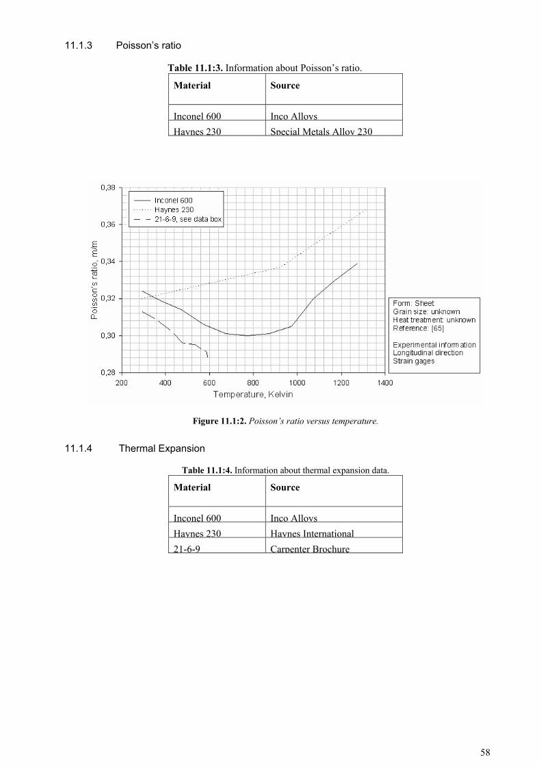
11.1.3 Poisson’s ratio
Table 11.1:3. Information about Poisson’s ratio.
Material Source
Inconel 600 Inco AlloysHaynes 230 Special Metals Alloy 230
Figure 11.1:2. Poisson’s ratio versus temperature.
11.1.4 Thermal Expansion
Table 11.1:4. Information about thermal expansion data.
Material Source
Inconel 600 Inco AlloysHaynes 230 Haynes International21-6-9 Carpenter Brochure
58

Temperature (K)
0 200 400 600 800 1000 1200 1400
Ther
mal
exp
ansi
on (1
e-6/
K)
10
12
14
16
18
20
22Inconel 600Haynes 23021-6-9
Figure 11.1:3. Thermal expansion versus temperature
11.1.5 Thermal Conductivity
Table 11.1:5. Information about Thermal Conductivity data.
Material Source
Inconel 600 Inco AlloysHaynes 230 Haynes International21-6-9 Carpenter Brochure
Temperature (K)
0 200 400 600 800 1000 1200 1400
Ther
mal
con
duct
ivity
(W/m
.K)
5
10
15
20
25
30
35Inconel 600Haynes 23021-6-9
Figure 11.1:4. Thermal Conductivity versus temperature
59

11.2 MECHANICAL PROPERTIES
11.2.1 Tensile Strength
Figure 11.2:1. Ultimate tensile Strength versus temperature for Nitronic 40
11.2.2 Yield Strength
Figure 11.2:2. Yield Strength versus temperature for Nitronic 40
60

11.2.3 Elongation
Figure 11.2:3. Elongation versus temperature
11.2.4 Reduction of area
Figure 11.2:4. Reduction of area versus temperature
61

11.2.5 Creep properties
Table 11.2:1. Typical Creep strength of 21-6-9 annealed bar [66b].
Stress for creep of
Test temperature, K 0.1% in 1000 hours 0.01% in 1000 hours
922 99 MPa 70 MPa
1005 44 MPa 28 MPa
Figure 11.2:5. 21-6-9 stress versus time at 533 K for various creep strains
Figure 11.2:6. 21-6-9 stress versus time at 644 K for various creep strains
62

Figure 11.2:7. 21-6-9 stress versus time at 755 K for various creep strains
Figure 11.2:8. Creep rupture behaviour for annealed 21-6-9 bar and sheet
11.2.6 Low cycle fatigue properties
LCF data for 21-6-9 between cryogenic to room temperature can be found in figure 11.2:9. Tests performed in hydrogen environment and hold time effects were not found in the literature review.
63

Figure 11.2:9. 21-6-9 LCF from cryogenic to room temperature
11.2.7 High cycle fatigue properties
Figure 11.2:10. 21-6-9 HCF from room to elevated temperature for smooth and notched samples
64

Figure 11.2:11. 21-6-9 HCF at 4 K
11.2.8 Crack propagation properties
Figure 11.2:12. Fatigue crack growth behaviour of various 21-6-9 plate at cryogenic to room temperature
65
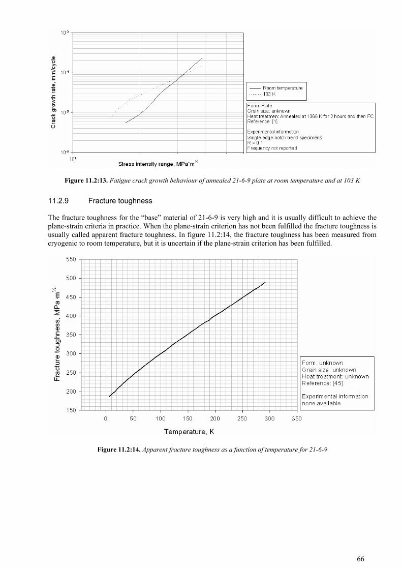
Figure 11.2:13. Fatigue crack growth behaviour of annealed 21-6-9 plate at room temperature and at 103 K
11.2.9 Fracture toughness
The fracture toughness for the “base” material of 21-6-9 is very high and it is usually difficult to achieve the plane-strain criteria in practice. When the plane-strain criterion has not been fulfilled the fracture toughness is usually called apparent fracture toughness. In figure 11.2:14, the fracture toughness has been measured from cryogenic to room temperature, but it is uncertain if the plane-strain criterion has been fulfilled.
Figure 11.2:14. Apparent fracture toughness as a function of temperature for 21-6-9
66

11.3 MECHANICAL PROPERTIES OF WELDED MATERIAL
11.3.1 Yield and tensile strength of welds
The strength differs between different filler metals but in general the strength of the welded joints in the as-welded condition have strength at least equal to the unwelded base metal [65]. In table 11.3:1, the cryogenic and room temperature yield and tensile strength for thick-section weldments with various filler metals have been measured. [9]
Table 11.3:1. Yield and tensile strength for various thick section TIG-welds [9].
Filler metal Test temperature, K Yield strength, MPa Tensile strength, MPa
40W 300 552 724
77 1051 1358
35W 300 593 762
77 979 1400
21-6-9 300 579 793
77 1182 1569
Inconel 625 300 514 814
77 738 1124
Inconel 625+ 300 500 796
77 696 1110
Inconel 82 300 486 714
77 690 965
Inconel 182 300 403 631
77 527 900
Base metal 21-6-9 300 345 690
77 970 1510
The yield and tensile strength variations from room to elevated temperature for GMA welded sheet and strip can be seen in figure 11.3:1.
67

Figure 11.3:1. Yield and tensile strength for GMA welded 21-6-9
For reference the yield and tensile strength for Haynes 230 can bee seen in table 11.3:2.
Table 11.3:2. Yield and tensile strength for TIG-welded Haynes 230 [93] and 21-6-9 [9] at room temperature.
Material Form Yield strength, MPa
Tensile strength, MPa
Haynes 230 Sheet 380 880
21-6-9a Plate 345 690
21-6-9 TIG a Plate 579 793a) See table 11.3:1.
68
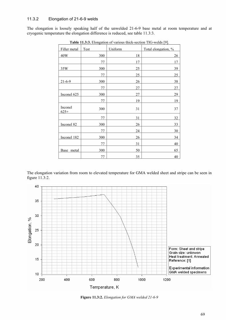
11.3.2 Elongation of 21-6-9 welds
The elongation is loosely speaking half of the unwelded 21-6-9 base metal at room temperature and at cryogenic temperature the elongation difference is reduced, see table 11.3:3.
Table 11.3:3. Elongation of various thick-section TIG-welds [9].
Filler metal Test Uniform Total elongation, %
40W 300 18 26
77 17 17
35W 300 25 39
77 25 25
21-6-9 300 26 38
77 27 27
Inconel 625 300 27 29
77 19 19
Inconel 625+
300 31 37
77 31 32
Inconel 82 300 26 33
77 24 30
Inconel 182 300 26 34
77 31 40
Base metal 300 50 65
77 35 40
The elongation variation from room to elevated temperature for GMA welded sheet and stripe can be seen in figure 11.3:2.
Figure 11.3:2. Elongation for GMA welded 21-6-9
69

11.3.3 Impact toughness of welds
The impact values for the ferrite containing filler metals are good at room temperature but at cryogenic temperature the impact toughness are severely affected by the brittle ferrite, see table 11.3:4. E.g. the 40W filler metal which is similar to 21-6-9 but with a higher Creq/Nieq ratio (i.e. more retained ferrite) have only ~5% of the room temperature impact value at 77 K, compare this with the fully austenitic nickel alloys: Inconel 82 and Inconel 182 whom are almost unaffected by the cryogenic temperature. Also see discussion.
Table 11.3:4. Impact toughness of various thick-section TIG-welds [9].
Filler metal
Test temperature, K
Charpy V energy, J Filler metal
Test temperature, K
Charpy V energy, J
40W 300 168 Inconel 625+ 300 75
77 9 77 55
35W 300 166 Inconel 82 300 169
77 17 77 160
21-6-9 300 202 Inconel 182 300 129
77 28 77 111 Inconel 625 300 36
Base metal 21-6-9 300 >300
77 22 77 100
11.3.4 Fracture toughness of welds
Table 11.3:5. Apparent fracture toughness at 4 K for 21-6-9 plate welded with Inconel 625 filler metal [31].
Weld process Specimen type
Apparenta
fracture toughness, MPa*m½
- Base metal 145
SMA Weld 135
SMA HAZb 115
GTA Weld 133
GTA HAZb 119
GMA Weld 149
GMA HAZb 130 a) Test conducted according to ASTM E 399 but did not meet requirements for plane-strain fracture toughness. b) All HAZ specimens contained varying amounts of weld, HAZ and base metal.
The plane-strain fracture toughness for 21-6-9 welds with 21-6-9 filler metal have a toughness value of 57 MPa×m½ and 82 MPa×m½ at 4 K for GTA and GMA weld process respectively. [58] This reference is in poor condition so the values may not be correct.
70

12 APPENDICES
12.1 APPENDIX A
The job number used during this master thesis is 06-0808.
Table 12.1:1. Alloy analysis of the 1 mm thick sheet (laser) and 4.78 mm thick sheet (TIG). Element 1 mma 4.78 mmb Element 1 mm 4.78 mm C 0,03 0,02 Cr 19,83 20,01 Mn 9,01 9,66 Ni 7,07 7,5 Si 0,28 0,31 N 0,32 0,31 P 0,025 0,02 Mo 0,05 0,01 S <0,005 <0,002 Cu 0,17 0,01
a) marked with AMS 5595, tested and fulfilled the 21-6-9 ASM requirements for composition, grain size, tensile properties, hardness, bending and susceptibility to intergranular attack, b) not traceable (marked with carpenter), fulfilled the 21-6-9 ASM requirements for composition and hardness.
Table 12.1:2. Alloy analysis of the TIG weld’s fusion zone. Elementa C -b Cr 20,08Mn 7,46 Ni 7,35Si 0,51 N 0,23P 0,25 Mo - S - Cu - Al 0,25 Ca 0,13
a) X-ray analysis (Philips MagiX PW2424 x-ray spectrometer) on cut-out fusion zones and thereby the values should not by interpreted as usable values only as a verification that the filler metal used was a 21-6-9 alloy (base metal or welding grade e.g. 40W), b) not measured
Table 12.1:3. Welded mount identification number.
Mount number Type
M06-2288 Base
M06-2257 TIG
M06-2173 TIG
M06-2175 Laser weld
M06-2172 Laser weld, heat-treated
Table 12.1:4. Tensile test specimens.
Identification number
Type, test temperature Test temperature Mount number
11 Weld, RT RT M06-2207
12 Weld, RT RTa
13 Weld, ET 866 K
14 Weld, ET not used
21 Weld, ET 866 K M06-2207
71

22 Weld, RT not used
23 Weld, RT RT
24 Weld, RT RTa M06-2207
25 Weld, RT not used
31 Base, ET 866 K
32 Base, ET 866 K M06-2208
33 Base, RT RT
34 Base, RT RT M06-2208
a) Heat treated: 1255 K ± 8 K for 30 min ± 5 min
Table 12.1:5. Liquid copper embrittlement test. Mount number
M06-2318 The 33 MPa stripe
.
Table 12.1:6. Etchants used in this report. Microstructure/phase Etchant Grain boundary 60% HNO3, electrolytic etching with 1.1 V Grain boundary carbides Oxalic acid, electrolytic etching with 6 V δ-ferrite 20% NAOH, electrolytic etching with 20 V
72